The Rion-Antirion Bridge Concept, Design and Construction
- 格式:pdf
- 大小:3.66 MB
- 文档页数:12

Traveling has always been a passion of mine, offering me a chance to explore new cultures, landscapes, and experiences. One of the most memorable trips Ive taken was to the enchanting city of Paris, France.The journey began with a flight that landed me in the heart of Europe. As I stepped out of the airport, the crisp air and the bustling city life instantly invigorated me. Paris, known as the City of Lights, did not disappoint. The Eiffel Tower, standing tall and proud, was the first sight that greeted me, and it was a breathtaking spectacle. The intricate ironwork of the tower, bathed in the golden glow of the setting sun, was a sight to behold.I spent my days wandering through the charming streets of Paris, each corner revealing a new delight. The city is a living museum, with its historic architecture telling stories of a bygone era. I visited the Louvre Museum, where I was awestruck by the vast collection of art, including the enigmatic smile of the Mona Lisa. The museums glass pyramid entrance was a marvel of modern architecture, contrasting beautifully with the classical facade of the Louvre.No trip to Paris would be complete without a visit to the NotreDame Cathedral. Its Gothic architecture and the detailed sculptures adorning the facade were a testament to the craftsmanship of the past. I was fortunate enough to hear the cathedrals bells chime, a sound that resonated through the city, filling the air with a sense of history and reverence.The food in Paris was an adventure in itself. I indulged in the citys culinary delights, from the flaky croissants and buttery pastries in the morning tothe rich, creamy cheeses and decadent chocolate desserts in the evening. Dining at a traditional French bistro was an experience that I will cherish, with the warm atmosphere and the aroma of delicious food wafting through the air.One of the highlights of my trip was a boat ride along the Seine River. The citys landmarks, illuminated against the night sky, created a magical atmosphere. The lights of the Eiffel Tower twinkled like stars, and the reflections of the city on the waters surface added an ethereal quality to the scene.My visit to Paris was not just a vacation it was an immersion into a culture that values art, history, and the simple pleasures of life. The citys charm is not just in its landmarks but in the everyday momentsthe laughter of children in a park, the clinking of glasses in a café, and the soft melody of a street performers accordion.As my time in Paris came to an end, I felt a sense of sadness but also a deep gratitude for the experiences I had. The city had left an indelible mark on my heart, and I knew that I would carry the memories of its beauty, its culture, and its people with me wherever I went.Traveling to Paris was more than just a trip it was a journey of discovery, a chance to connect with a city that has inspired artists, writers, and dreamers for centuries. It taught me to appreciate the beauty in the world around me and to seek out new experiences that enrich my life. As I boarded the plane to return home, I couldnt help but feel that a part ofParis would always be with me, a reminder of the magic and wonder that can be found when we step out of our comfort zones and explore the world.。


As a seasoned film critic, I find it a privilege to delve into the cinematic experiences that leave an indelible mark on the viewers psyche. Braveheart, directed by and starring Mel Gibson, is one such film that resonates with a profound sense of history, heroism, and human spirit. This epic historical drama, released in 1995, is a testament to the power of storytelling when it is steeped in the rich tapestry of Scotlands struggle for freedom.From the moment the opening credits roll, accompanied by James Horners hauntingly beautiful score, Braveheart immerses the audience in the raw and rugged landscape of medieval Scotland. The films narrative unfolds through the eyes of its protagonist, William Wallace, a man whose life is a relentless pursuit of liberty and justice. Gibsons portrayal of Wallace is nothing short of iconic, capturing the essence of a man driven by love, loss, and an unwavering commitment to his peoples freedom.The films visual storytelling is equally compelling. The cinematography by John Toll is breathtaking, capturing the stark beauty of the Scottish highlands and the brutality of medieval warfare. The battle scenes are expertly choreographed, creating a visceral experience that leaves the viewer both awestruck and heartbroken. The climactic Battle of Stirling Bridge is a masterclass in cinematic tension, showcasing the strategic brilliance of Wallace and the ferocity of his warriors.One cannot discuss Braveheart without acknowledging its historical inaccuracies. While the film takes some liberties with the facts, it is important to remember that it is a work of fiction inspired by history. The films primary purpose is not to provide a strict account of historical eventsbut to evoke an emotional response and ignite a passion for the ideals of freedom and justice.The performances in Braveheart are uniformly excellent. Patrick McGoohan as the cruel King Edward I, Sophie Marceau as the compassionate Princess Isabelle, and James Cosmo as the loyal Campbell, all contribute to a rich ensemble that brings depth and nuance to the story. The dialogue, though occasionally anachronistic, is powerful and evocative, with lines such as Every man dies, not every man really lives that have become ingrained in popular culture.What sets Braveheart apart from other historical dramas is its ability to balance the grand spectacle of war with intimate moments of humanity. The love story between Wallace and Murron MacClannough, played by Catherine McCormack, is tender and tragic, providing a poignant counterpoint to the films larger themes of war and sacrifice.Braveheart is not without its flaws. Some critics argue that the film romanticizes violence and simplifies complex historical events. However, these criticisms do not detract from the films overall impact. Braveheart is a powerful cinematic experience that speaks to the enduring human desire for freedom and the courage to fight for what is right.In conclusion, Braveheart is a film that has stood the test of time, its themes and imagery as relevant today as they were over two decades ago. It is a visual and emotional tour de force that challenges the viewer to consider the true cost of freedom and the sacrifices made by those whohave fought for it. As a film critic, I can attest that Braveheart is not just a movie it is an experience that will stay with you long after the credits have rolled.。

世界著名桥梁赏析Appreciation of World Famous Bridges李伟东1目录/ CONTENTSForth Bridge Brooklyn Bridge 12London Tower Bridge 78Sydney Harbour Bridge San Francisco-Oakland Bay Bridge34Millau Bridge 910Rion-AntirionBridge Golden Gate Bridge 511Samuel Beckett Bridge Bixby Bridge6122“美就是感性认识的完善。
”鲍姆加登近代哲学家对美学的看法“一切绝妙的美都显示出奇异的均——美学的创立者鲍姆▪加登“美就是理性的感性显现,以最完善的方式表达最高尚的思想那就是美“衡关系。
”——弗朗西斯▪培根的标准式,表达最高尚的思想,那就是美。
——黑格尔“最动人的美好像是最完善地表达材料强最动人的美好像是最完善地表达材料强度与荷重之间的斗争所形成的。
”——叔本华“桥梁艺术”“功能合理就是美。
”——路易斯▪沙利文有其独特的美!301Forth Bridge —福斯桥WORK REPORT4Forth Bridge5Forth Bridge晚晴风云人物曾国藩两位著名弟子之一1896年出访俄、德、荷、比、8法、英、美、加国参观福斯桥6李鸿章Forth Bridge福斯桥地理位置Forth Bridge福斯桥位于苏格兰首府爱丁堡城北福斯湾。
7Forth Bridge 福斯桥地理位置Forth Rail Bridge(1890)Forth Road Bridge(1964)Queensferry Bridge(2017)8Forth Bridge9Forth Bridge早在1806年,人们就提出于福斯湾建立隧道,1818年,James Anderson (詹姆斯ꞏ安德森)第一个提出在福斯湾建立桥梁,但被铁路委员会驳回,直到半个多世纪后,这项决议才正福斯桥简介式被通过,并由Thomas Bouch(托马斯ꞏ布奇)主持修建。

The rich tapestry of history is a testament to the enduring legacy of human civilization.It is a narrative woven with threads of triumph,tragedy,innovation,and resilience.The depth and breadth of historical knowledge not only provide us with a profound understanding of our past but also offer invaluable lessons that guide our present and shape our future.Ancient Civilizations:The Cradle of HistoryThe history of human civilization began with the rise of ancient civilizations such as the Egyptians,Mesopotamians,Indians,and Chinese.These societies laid the foundation for complex systems of governance,agriculture,art,and religion.The pyramids of Egypt,the cuneiform script of Mesopotamia,and the Vedic hymns of India are but a few examples of the rich historical heritage that continues to inspire awe and curiosity.The Renaissance:A Rebirth of KnowledgeThe Renaissance period in Europe marked a significant shift in the historical narrative.It was a time of rediscovery and revival of classical knowledge,art,and literature.This era saw the emergence of great minds like Leonardo da Vinci and Michelangelo,whose contributions to art and science have left an indelible mark on human history.The Industrial Revolution:Transforming the WorldThe18th and19th centuries witnessed the Industrial Revolution,a period that dramatically altered the landscape of human society.The invention of machinery and the shift from agrarian to industrial economies led to unprecedented economic growth and urbanization.This period also saw the rise of new social classes and the beginning of the modern labor movement.The World Wars:A Test of HumanityThe20th century was marked by two devastating global conflicts,World War I and World War II.These wars not only resulted in immense loss of life and destruction but also led to significant political and social changes.The establishment of the United Nations and the pursuit of international cooperation emerged as a response to the horrors of war.The Digital Age:A New Chapter in HistoryIn recent decades,the advent of the digital age has revolutionized the way we live,work, and communicate.The internet,artificial intelligence,and social media have transformed societies and economies,creating new opportunities and challenges.This era is still unfolding,with its full impact on history yet to be fully understood.Cultural Exchange and GlobalizationThroughout history,the exchange of ideas,goods,and people across borders has enriched the global cultural landscape.The Silk Road,the Age of Exploration,and modern globalization are examples of how human interaction has led to the blending of cultures, fostering diversity and understanding.The Importance of Historical PreservationPreserving historical sites,artifacts,and knowledge is crucial for maintaining a connection to our past.Museums,archives,and educational institutions play a vital role in safeguarding and sharing the stories of our ancestors,ensuring that future generations can learn from and appreciate the rich history that has shaped the world.The Role of History in Shaping IdentityHistory is not just a collection of facts and dates it is the story of who we are and where we come from.It helps us understand our cultural identity,values,and beliefs.By studying history,we can gain insights into the forces that have shaped our societies and the individuals who have left their mark on the world.In conclusion,the richness of history is a treasure trove of knowledge and experience that offers us a deeper understanding of the human journey.It is through the study and appreciation of history that we can learn from the past,navigate the complexities of the present,and prepare for the challenges of the future.。


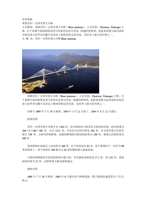
世界明桥希腊里约—安蒂里奥大吊桥文本摘要:希腊里约—安蒂里奥大吊桥(Rion-Antirion),正式名称:Charilaos Trikoupis大桥,位于希腊中部的帕特雷湾与科林西亚湾交界处,跨越科林斯湾,连接着希腊大陆西部的安提里翁与伯罗奔尼撒半岛西北上帕特雷附近的里翁,是世界上最大的吊桥之一。
关键词:里约—安蒂里奥大吊桥Rion-Antirion--------------------------------------------------------------------------------希腊里约—安蒂里奥大吊桥(Rion-Antirion),正式名称:Charilaos Trikoupis大桥,位于希腊中部的帕特雷湾与科林西亚湾交界处,跨越科林斯湾,连接着希腊大陆西部的安提里翁与伯罗奔尼撒半岛西北上帕特雷附近的里翁,是世界上最大的吊桥之一。
该桥于1998年7月19日奠基,2004年5月21日竣工,2004年8月12日通车。
桥梁结构里约—安蒂里奥大吊桥全长2,883米,其中跨海的主桥采用五跨连续结构,跨径组成为286+3×560+286 米,全长2252 米,从里约方向的引桥长392米,从安蒂里奥方向的引桥长239米。
主桥有四座桥墩,边缘的桥墩到引桥间的距离为286米,桥墩之间的距离为560米。
每座桥墩在海面以上的高度为160米,水下的高度达65米。
每个桥墩位于一直径为90米的地基上,每个地基有200根长达30米的钢柱插入海底组成。
大桥的伸缩缝是目前类似桥梁中最大的。
在其最高处桥面宽27.2米,厚2.82米,离海面的高度为52米,这样即使大船也能够通过。
建桥历程1998年7月19日奠基,2004年6月最后两个桥墩连接,整个建筑的建造费为7.71亿欧元。
2004年8月7至8日通过一个盛大仪式和焰火晚会大桥正式启用。
在仪式上希腊国家足球队教练奥托·雷哈格尔、波兰奥林匹克金牌选手Irina Szewinska和希腊奥林匹克足球队教练Stratos Apostolakis持奥林匹克火炬跑过大桥。

视幻艺术——布里奇特·赖利(Bridget Riley)布里奇特·路易斯·赖利(Bridget Louise Riley 1931—),是一位有创造性的英国女画家。
她是光效应绘画的奠基人之一,也是欧普艺术的杰出代表。
被誉为“欧普艺术”的创始人之一。
代表作《瀑布第三号》(1967,英国国会罗曼美术馆)。
赖利进入欧普艺术时期的原因与儿时居住的乡下饱受阳光直射的经历有关。
在太阳的照射下,所有的景物非常融合,除去形体以外的能量(纯粹的能量),作品均在表达流动。
在赖利的作品中,线条和色彩都表现为一种线条律动的美感,她认为反复是一种扩大器,可以增强这种律动的能量。
孩提时代,赖利对自然现象有着敏捷的反应力,尤其是自然界的光和色。
尽管她成熟时期的作品不来自于自然界的观察,然而却与对自然界的体验紧密相关。
赖利花了二年时间临摹乔治·修拉(Georges Seurat)的绘画,学习其点彩绘画技术和颜色的运用,她描述这个过程为关于颜色的启示。
1966年赖利开始运用颜色达到新的光学效果,通过纯色补色的并置来影响各个颜色被感知的明度,赖利非常小心翼翼严谨的选色配色,以达到她想要的色调和亮度。
她在树胶水彩画的研究中探索到色彩的交互作用,观赏者的视线很自然地随着并置的线条平行移动,并感受到爱抚和安慰,体验摩擦和破裂、滑翔和漂泊。
这种艺术和自然界平行的联系是赖利作品不断发展的有力支撑。
1986年她遇见了后现代主义画家菲利浦·塔菲(Philip Taaffe)和罗丝·布莱克纳(Ross Bleckner),在她的作品中引进了关系元素概念,这增加了她对颜色并置迷恋的另一个维度。
赖利的作品是律动的视觉魔术。
她不仅自得其乐的设计着作品,更在其中注入了对人生与命运的思考。
作品多以抽象的几何形及渐变的明暗和色彩不同组合,造成观赏者视觉上的错觉或幻觉效果。
无论是想象的延续,还是存在的延续;无论是看得见的线条还是看不见的线条,从根本上说还是属于构成艺术。

London Tower Bridge is an iconic symbol of the city and a marvel of Victorian engineering.It spans the River Thames and connects the boroughs of Southwark and Tower Hamlets,providing a vital link for both vehicles and pedestrians.Constructed between1886and1894,the bridge was designed by Sir Horace Jones and engineered by Sir John Wolfe Barry.The design was chosen after a competition that sought a bridge that would be both functional and aesthetically pleasing.The result is a combination of a suspension bridge and a bascule bridge,allowing the central sections to rise and allow ships to pass through.The bridges most distinctive feature is its two towers,which stand65meters high and are adorned with intricate Victorian Gothic detailing.These towers are made of steel and granite,and they support the weight of the bridges walkways and the bascule mechanism. The walkways are lined with a glass floor,offering visitors a unique view of the Thames below.One of the most fascinating aspects of Tower Bridge is its operation.When a large ship needs to pass through,the bridges central sections are raised,a process that takes about five minutes.This is done using a system of counterweights and hydraulics,which was stateoftheart technology at the time of the bridges construction.Today,Tower Bridge is not only a vital part of Londons infrastructure but also a popular tourist attraction.Visitors can explore the bridges Victorian Engine Rooms,which house the original steam engines that once powered the bascule mechanism.There is also an exhibition that tells the story of the bridges construction and history.In addition to its engineering prowess,Tower Bridge is also known for its striking appearance,particularly when illuminated at night.The bridge is often lit up for special occasions and events,adding to the citys vibrant atmosphere.In conclusion,London Tower Bridge is a testament to the ingenuity and craftsmanship of the Victorian era.Its unique design,rich history,and strategic location make it an essential part of Londons landscape and a mustvisit destination for anyone visiting the city.。

国宝级文物法国蓬皮杜艺术中心的展品法国蓬皮杜艺术中心是世界上最著名的艺术中心之一,也是法国的国宝级文物。
它位于法国巴黎市中心的蓬皮杜广场,是一座由英国建筑师理查德·罗杰斯设计的建筑物。
蓬皮杜艺术中心以其独特的建筑风格和丰富多样的展品而闻名于世。
蓬皮杜艺术中心的展品丰富多样,包括绘画、雕塑、摄影、装置艺术等多种艺术形式。
这些展品来自世界各地的艺术家,代表了不同的艺术风格和时代背景。
以下是一些蓬皮杜艺术中心的展品介绍。
首先是绘画作品。
蓬皮杜艺术中心收藏了许多重要的绘画作品,包括莫奈、梵高、毕加索等世界知名艺术家的作品。
其中最著名的是莫奈的《睡莲》系列,这是莫奈晚年创作的一组作品,以其独特的色彩和光影效果而闻名于世。
其次是雕塑作品。
蓬皮杜艺术中心的雕塑作品丰富多样,包括传统的大理石雕塑和现代的金属雕塑等。
其中最著名的是罗丹的《思想者》,这是一座青铜雕塑,代表了人类思考的力量和智慧。
此外,蓬皮杜艺术中心还展示了许多摄影作品。
摄影作为一种新兴的艺术形式,已经成为当代艺术的重要组成部分。
蓬皮杜艺术中心收藏了许多重要的摄影作品,包括安塞尔·亚当斯、罗伯特·卡帕等世界知名摄影师的作品。
这些作品通过镜头记录了人类社会的变迁和个人的情感体验。
最后是装置艺术。
装置艺术是一种以空间为媒介的艺术形式,通过创造具有特定意义和情感的空间来引发观众的思考和感受。
蓬皮杜艺术中心展示了许多令人惊叹的装置艺术作品,包括安尼什·卡普尔的《云门》和克里斯蒂安·博尔赫斯的《心灵之眼》等。
这些作品通过独特的材料和形式,创造了令人难忘的艺术体验。
总之,蓬皮杜艺术中心的展品丰富多样,代表了世界各地不同艺术家的创作成果。
这些展品通过艺术的语言,向观众传递了艺术家的思想和情感。
蓬皮杜艺术中心作为法国的国宝级文物,不仅是艺术的殿堂,也是人类文明的见证。
每年吸引了数以百万计的游客前来参观,成为了法国乃至全世界的文化瑰宝。


The Rion-Antirion BridgeConcept, Design and ConstructionJ. Combault 1 and J.P. Teyssandier 21Jacques Combault, Technical Advisor, 27, rue Edgar Degas, 78360 Montesson, France; PH 33 6 12 22 99 68; email: bault@free.fr 2Jean-Paul Teyssandier, Chairman & Managing Director, GEFYRA S.A. (VINCI), 2Rizariou str., 15233 Halandri, Greece; PH +30210 68 58 196; FAX ….…58786; email: teyssandier@AbstractOpened to traffic in August 2004, the Rion-Antirion Bridge crosses the Gulf of Corinth near Patras in western Greece. It consists of an impressive multi cable-stayed span bridge, 2,252 m long connected to the land by two approaches.An exceptional combination of physical conditions made this project quite unusual: high water depth, deep strata of weak soil, strong seismic activity and fault displacements. In addition a risk of heavy ship collision had to be taken into account.The structure has been designed in view of challenging the earthquakes and ensuring the every day serviceability of the link as well. To make the bridge feasible, innovative techniques had to be developed: The strength of the in-situ soil has been improved by means of inclusions; the bridge deck has been suspended on its full length, and therefore isolated as much as it can be.Due to high water depth,construction of the main bridge of the Rion-Antirion Crossing had to face major difficulties. In relation with this, foundation works, including dredging, steel pipe driving, but also precise laying of the required gravel bed under the pylon bases, were forming an impressive work package requiring unusual skills and equipment.To achieve this task, the conceptual design of the entire structure made it possible to simplify, in terms of implementation and reliability, the concept of huge shallow foundations and to prefabricate the major components of a bridge in the most favourable conditions, combining the latest technologies available in the constructionof concrete off-shore oil drilling platforms and large cable stayed bridges.D o w n l o a d e d f r o m a s c e l i b r a r y .o r g b y T o n g j i U n i v e r s i t y o n 07/10/13. C o p y r i g h t A S CE .F o r p e r s o n a l u s e o n l y ; a l l r i g h t s r e s e r v e d .IntroductionLocated between the Peloponese and the continent, at the entry of the Gulf of Corinth in Western Greece, the Rion-Antirion Bridge is intended to replace an existing ferry system.An exceptional combination of environmental and physical conditions made the project quite complex:•large water depth (up to 65 m)•deep soil strata of weak alluviums•strong seismic activity•possible tectonic movements Indeed, the structure spans a stretch of water about 2,500 m long. The seabed presents fairly steep slopes on each side and a long horizontal plateau at a depth of 60 to 70m.No bedrock has been encountered during soil investigations down to a depth of 100m. Based on a geological study, it is believed that the thickness of sediments is greater than 500 m.General trends identified through soils surveys are the following:•a cohesionless layer is present at mudline level consisting of sand and gravel to a thickness of 4 to 7 m, except in one location (near the Antirion side),where its thickness reaches 25m.•underneath this layer, the soil profile, rather erratic and heterogeneous, presents strata of sand, silty sand and silty clay.•below 30 m, the soils are more homogeneous and mainly consist of clays or silty clays.In view of the nature of the soils, liquefaction does not appear to be a problem except on the north shore, where the first 20 m are susceptible of liquefaction.The seismic conditions to be taken into account are presented in the form of a response spectrum at seabed level (see Figure 1). The peak ground acceleration is equal to 0.48 g and the maximum spectral acceleration is equal to 1.2g between 0.2and 1.0 s. This spectrum is supposed to correspond to a 2000 year return period.Figure 1- Design horizontal spectrumD o w n l o a d e d f r o m a s c e l i b r a r y .o r g b y T o n g j i U n i v e r s i t y o n 07/10/13. C o p y r i g h t A S CE .F o r p e r s o n a l u s e o n l y ; a l l r i g h t s r e s e r v e d .It is worth mentioning that the Peloponese drifts away from mainland Greece by a few millimetres per year. For that reason, contractual specifications required the bridge to accommodate possible fault movements up to 2 m in any direction, horizontally and/or vertically, between two adjacent supports.In addition, the bridge supports must be capable to withstand the impact from a 180,000 dwt tanker sailing at 16 knots.Of course, all these difficulties could have been taken into account separately, without major problem, but the conjunction of all these adverse conditions was leading to a formidable challenge. Since a major slope stability problem on the Antirion side eliminated the design of a suspension bridge, from the very beginning of the conceptual design stage, the bridge type and the span lengths had to be selected to simply make the bridge feasible and the global cost of the project acceptable by limiting the number of supports located in the strait and, finally, anexceptional multi-cable-stayed-span bridge was selected.Figure 2– Bridge ElevationDescription of the Main BridgeConnected to the land by two approaches, respectively 392 m long on the Rion side and 239 m long on the Antirion side, this exceptional cable-stayed bridge (see Figure 2) consists of three central spans, 560m long, and two side spans, 286m long.FoundationsThe four pylons of the main bridge simply rest on the seabed through a large concrete substructure foundation, 90m in diameter, 65m high at the deepest location (see Figure 3).To provide sufficient shear strength to the top 20 m of soils, which are rather heterogeneous and of low mechanical characteristics, the upper soil layer of theD o w n l o a d e d f r o m a s c e l i b r a r y .o r g b y T o n g j i U n i v e r s i t y o n 07/10/13. C o p y r i g h t A S CE .F o r p e r s o n a l u s e o n l y ; a l l r i g h t s r e s e r v e d .seabed is reinforced by inclusions to resist large seismic forces unavoidably comingfrom structural inertia forces and hydrodynamic water pressures.Figure 3-Foundation and inclusions: An innovative foundation concept These inclusions are hollow steel pipes, 25 to 30 m long, 2 m in diameter, driven into the upper layer at a regular spacing of 7 to 8 m (depending on the pier).About 150 to 200 pipes weredriven in at each pier location. Theyare topped by a 3 m thick, properlylevelled gravel layer, on which thefoundations rest.Due to the presence ofa thick gravel layer,these inclusionsare not required under one pylon.PylonsThe pylon bases consist of a 1m thick bottom slab and 32 peripheralcells enclosed in a 9m high perimeterwall and covered by a top slab slightlysloping up to a conical shaft. For thedeepest pier, this cone, 38m indiameter at the bottom, 27 m at the top,rises 65m over the gravel bed up to 3 mabove sea level.These huge bases support,through vertical octagonal pylon shafts,24 m wide and nearly 29m high, a15.8m high pyramidal capital whichspreads to form the 40.5 m wide square base of four concrete legs.Figure 4– Global view of aPylonD o w n l o a d e d f r o m a s c e l i b r a r y .o r g b y T o n g j i U n i v e r s i t y o n 07/10/13. C o p y r i g h t A S CE .F o r p e r s o n a l u s e o n l y ; a l l r i g h t s r e s e r v e d .Rigidly embedded in the capital to form a monolithic structure,the four legs (4.00 m x 4.00 m),made of high strength concrete, are 78m high; they converge at their tops to impart the rigidity necessary to support asymmetrical service loads and seismic forces.They are topped by a pylon head, 35m high, comprising a steel core embedded in two concrete walls, where stay cables are anchored.From sea bottom to pylon top, the pylons are up to 230 m high (see Figure 4).Deck and CablesThe deck is a composite steel-concrete structure, 27.20m wide, made of a concrete slab,25 to 35 cm thick, connected to twin longitudinal steel I girders, 2.20 m high, braced every 4m by transverse cross beams (see F igure 5 and Figure 6).Figure 5-Typical deck cross sectionIt is fully suspended from 8 sets of 23 pairs of cables and continuous over its total length of 2,252m, with expansion joints at both ends.In the longitudinal direction, the deck is free to accommodate all thermal and tectonic movements and the joints are designed to accommodate 2.5m displacements under service conditions and movements up to 5.0 m under an extreme seismic event.In the transverse direction it is connected to each pylon with 4 hydraulic dampers of 3,500 KN capacity each and an horizontal metallic strut of 10,000 KN capacity (see Figure 6.The stay cables are arranged in two inclined planes according to a semi-fan shape. They are made of 43 to 73 parallel galvanised strands individually protected.Main bridge concept and design philosophyFrom the beginning it has been clear that the critical load for most of the structure was the design seismic loading [3]. The impact from the 180,000 DWT tanker, equivalent to a static horizontal force of 280MN at sea level, generates horizontal forces and overturning moments at the soil-pylon base interface which are smaller than seismic loads generated according to the design spectrum and whichonly necessitates a local strengthening of the pylons in the impact zone.D o w n l o a d e d f r o m a s c e l i b r a r y .o r g b y T o n g j i U n i v e r s i t y o n 07/10/13. C o p y r i g h t A S CE .F o r p e r s o n a l u s e o n l y ; a l l r i g h t s r e s e r v e d .In environmental conditions characterized by poor soil conditions, significant seismic accelerations and unusual water depth,the primary major concerns were the soil bearing capacity and the feasibility of the required foundations. Alternative foundation concepts (such as friction pile foundations, deep embedded caissons and soil substitution) have been investigated with their relative merits in terms of economy, feasibility and technical soundness [2].This analysis showed that a shallow foundation was the most satisfactory solution as long as it was feasible to significantly improve the top 20 m of soils. This has been achieved by means of metallic inclusions, as described here above. Although these foundations looks like piled foundations, they do not at all behave as such: no connection exists between the inclusions and the caisson raft, which will allow for the pylon bases to partially uplift or to slide with respect to the gravel bed; the density of inclusions is much more important and the length smaller than would have been the case if piles had been used.This type of soil reinforcement through metallic inclusions was quite innovative and necessitated extensive numerical studies and centrifuge model tests in the Laboratoire Central des Ponts et Chaussées (France) which validated the concept.The other major points of concern were the large tectonic displacements and the high value of seismic forces to be resisted by the structure. Several possible solutions in terms of structural flexibility were tested but, as long as the pylon bases could move on the gravel bed, it was found that the best way to solve the problem was to make the pylons monolithic and the cable-stayed deck continuous,fully suspended and therefore isolated as much as it could be [1]. Like this, the deck will behave like a pendulum in the transverse direction during a severe seismic event, its lateral movements being buffered and limited by the hydraulic dampers located at each pylon, while it is kept in place during the strongest winds by the horizontal steel strut connected to each pylon which is intended to break only during a seismic eventof low occurrence (over 350 year return period).Figure 6– Fully suspended deck: Concept and connection to the pylonsThese unique features of the project significantly reduce seismic forces in the deck and allow the bridge to accommodate fault movements between adjacent piers thanks to its global structural flexibility.According to capacity design principles, theD o w n l o a d e d f r o m a s c e l i b r a r y .o r g b y T o n g j i U n i v e r s i t y o n 07/10/13. C o p y r i g h t A S CE .F o r p e r s o n a l u s e o n l y ; a l l r i g h t s r e s e r v e d .structure will only be the subject of “controlled damages” under the extreme seismic event at a limited number of well identified locations:•the pylon bases may slightly slide on the gravel bed and partially uplift;•plastic hinges may form in pylons legs;•the wind stabilising struts may fail and thus make the dampers free to operate both in tension and compression and able to dissipate a substantial amount of energy.The dynamic response of the structure was estimated with artificial and natural accelerograms matching the design spectrum. This analysis took into account large displacements, hysteretic behaviour of materials, non linear viscous behaviour of the energy dissipation devices, sliding and uplifting elements at the raft-soil interface and a geological model for the soil-structure interaction [2].In addition to this finite element analysis, a non linear 3D push over analysis was performed for the 4 leg pylons in order to estimate their remaining capacity after the formation of plastic hinges and to confirm their ductile behaviour.Finally, the dynamic relative movement between the deck and a pylon during an extreme seismic event being in the order of 3.50 m, with velocities up to 1.6 m/sec,a prototype test for the dampers was performed in the CALTRANS testing facility at the University of California San Diego and special concrete confinement tests on high strength concrete used for pylon legs,in order to define its strain-stress curves for various confinement ratios, were also performed in San Diego. ConstructionPylon bases were built in two stages near Antirion; the footings were cast first in a 230x 100 m dry dock and the conical shafts were completed in a wet dock.In the dry dock, two cellular pylon footings were cast at a time (see Figure 7). In fact, two different levels in the dock provided 12 m of water for the first footingand 8 m for the other one behind.Figure 7–Pylon bases: Works in the dry dockWhen the first footing, including a 3.2m lift of the conical shaft, was complete, the dock was flooded and the 17 m tall structure was towed out to the wet dock located 1km away (see F igure8).D o w n l o a d e d f r o m a s c e l i b r a r y .o r g b y T o n g j i U n i v e r s i t y o n 07/10/13. C o p y r i g h t A S CE .F o r p e r s o n a l u s e o n l y ; a l l r i g h t s r e s e r v e d .Figure 8– From the dry dock to the wet dockAn original idea allowed saving a significant amount of time in the production cycle of the pylon bases.Before the first tow-out, the dry dock was closed by a classical sheet piled dyke which had to be completely removed. Clearly, rebuild and remove again such a dyke would have been time consuming. In fact, the second footing, once moved forward to the deeper part of a the dry dock, was used as a gate after being properly equipped with temporary steel walls (see F igure 9).Figure 9– The dry dock: before and after towing outD o w n l o a d e d f r o m a s c e l i b r a r y .o r g b y T o n g j i U n i v e r s i t y o n 07/10/13. C o p y r i g h t A S CE .F o r p e r s o n a l u s e o n l y ; a l l r i g h t s r e s e r v e d .At the wet dock, where the water depth reaches 50m, the pylon base remained afloat (see Figure 10) and was kept in position by three big chains, two anchored in the sea and one on land. Cells in the base were used to keep the pylon base perfectlyvertical through a differential ballasting system controlled by computer.Figure 10– Pylon base at the wet dock: Progressing towards top of the coneAfter completion of the conical shaft, the pylon base was towed to its final position and immersed on the reinforced soil.Meanwhile, preparation ofthe seabed at the future locationsof pylon bases had beenundertaken (see Figure 11).Dredging the seabed,driving 200 inclusions, placing andlevelling the gravel layer on thetop, with a depth of water reaching65 m, was a major marineoperation which necessitatedspecial equipment and procedures.In fact, a tension-leg barge hasbeen custom-made, based on thewell known concept of tension-legplatforms but used for the firsttime for movable equipment.Figure 11– Driving the inclusions D o w n l o a d e d f r o m a s c e l i b r a r y .o r g b y T o n g j i U n i v e r s i t y o n 07/10/13. C o p y r i g h t A S C E . F o r p e r s o n a l u s e o n l y ; a l l r i g h t s r e s e r v e d .The barge was anchored to deadweights lying on the seabed throughvertical anchor lines (see Figure 12).The tension in these anchor lineswas adjusted in order to give therequired stability to the barge withrespect to sea movements and loadshandled by the crane disposed on itsdeck. By increasing the tension in theanchor lines, the buoyancy of the bargeallowed the dead weights to be liftedfrom the seabed; then the barge,including its weights, could be floatedaway to a new position.Figure 12– The tension leg bargeAfter being immersed at their final position, the pylon bases were filled with water to accelerate settlements, which were significant (between 0.2 and 0.3 m). This pre-loading was maintained during pier shaft and pier head construction, thusallowing a correction for potential differential settlements before erecting pylon legs.Figure 13– Pylon capital and pylon legs under constructionThe huge pyramidal capitals are key elements of the pylon structure, as they withstand tremendous forces coming from the pylon legs. During a major seismic event, three legs can be in tension, while all vertical loads are transferred to the fourth one. For that reason, these capitals are very heavily reinforced (up to 700kg / m3 concrete) and pre-stressed (see Figure 13). Their construction was probably the most strenuous operation of the project.Pylon legs during the construction required a heavy temporary bracing in order to allow them to resist to earthquakes (see Figure 13). This bracing could be removed once legs were connected together at their tops.The steel core of the pylon head was made of two elements which were placed at their final location by a huge floating crane able to reach a height of 170mabove sea level (see Figure 14).D o w n l o a d e d f r o m a s c e l i b r a r y .o r g b y T o n g j i U n i v e r s i t y o n 07/10/13. C o p y r i g h t A S CE .F o r p e r s o n a l u s e o n l y ; a l l r i g h t s r e s e r v e d .Figure 14– Placing the steel core of the pylon headThe method of construction of the composite steel – concrete deck was similar to the one successfully used on the second Severn crossing: deck segments, 12m long, were prefabricated on the yard, including their concrete slab.They were placed at their final location by the floating crane (see Figure 15) and bolted to the previously assembled segments, using the classical balanced cantilever erection method. Only small joints providing enough space for anappropriate steel reinforcement overlapping had to be cast in place.Figure 15– Placing 12 m long segmentsD o w n l o a d e d f r o m a s c e l i b r a r y .o r g b y T o n g j i U n i v e r s i t y o n 07/10/13. C o p y r i g h t A S CE .F o r p e r s o n a l u s e o n l y ; a l l r i g h t s r e s e r v e d .The deck was erected from two pylons at the same time. Five to seven decksegments were put in place each week. In total the deck erection took 13 months.ConclusionThe Rion – Antirion Bridge had to overcome an exceptional combination of adverse environmental conditions: water depth up to 65m, deep soil strata of weak alluviums, strong seismic activity and tectonic movements.This resulted in a unique multi-span cable-stayed bridge consisting of a continuous deck, 2252 metres long and fully suspended from four pylons.The pylons rest directly on the sea bed, through a gravel layer allowing them to be the subject of controlled displacements under the most severe earthquake. Based on an innovative concept,the top 20m of soils located under the large diameter bases (90 m) of three of the pylons are reinforced by means of metallic inclusions.The design and construction of this $ 800 million project have been undertaken under a private BOT scheme, led by the French company VINCI.Completed in August 2004, the Rion-Antirion Bridge has been opened to traffic 4 months before the contractual deadline.References[1]Combault, J. - Morand, P. - Pecker, A. (2000). Structural Response of the Rion-Antirion Bridge. 12th World Conference on earthquake Engineering. Auckland, New Zealand.[2]Pecker, A.(2003). Aseismic foundation design process, Lessons learned from two major projects: The Vasco da Gama and the Rion-Antirion Bridges. ACI International Conference on Seismic Bridge Design and Retrofit . La Jolla, California.[3]Teyssandier, J.P. -Combault, J. - Morand, P. (2000). The Rion-Antirion Bridge Design and Construction.12th World Conference on earthquake Engineering.Auckland, New Zealand.D o w n l o a d e d f r o m a s c e l i b r a r y .o r g b y T o n g j i U n i v e r s i t y o n 07/10/13. C o p y r i g h t A S CE .F o r p e r s o n a l u s e o n l y ; a l l r i g h t s r e s e r v e d .。

Visiting the United Nations Headquarters is an enlightening experience that offers a unique glimpse into the workings of one of the worlds most influential international organizations.Heres a detailed account of what one might expect and learn from such a visit.Arrival and First ImpressionsUpon arriving at the United Nations Headquarters in New York City,one is immediately struck by the iconic architecture.The complex,designed by architect Wallace K. Harrison and completed in1952,is a symbol of international cooperation and diplomacy. The Secretariat Building,with its39story glass curtain wall,is a modernist masterpiece that stands in stark contrast to the surrounding cityscape.Security and EntrySecurity at the UN is understandably tight,given the importance of the work conducted within its walls.Visitors must pass through a rigorous screening process,which includes a bag check and a body scan.This is a reminder of the serious nature of the UNs mission and the need to protect the diplomats and staff who work there.The Tour BeginsOnce inside,visitors are typically guided through the complex by knowledgeable tour guides who provide insights into the history and purpose of the UN.The tour often begins with a visit to the General Assembly Hall,where representatives from member states gather to discuss and vote on global issues.The grandeur of the hall,with its high ceiling and semicircular seating arrangement,conveys the gravity of the decisions made within. The Security Council ChamberNext,the tour may lead to the Security Council Chamber,a smaller and more intimate space where the UNs most critical security discussions take place.The chamber is designed to facilitate focused debate,with its circular table and seating for representatives and translators.The Economic and Social Council ChamberThe Economic and Social Council Chamber is another key stop on the tour.This is where discussions on economic,social,and environmental issues are held.The rooms design, with its large central table and comfortable chairs,is meant to encourage open dialogueand collaboration.The Dag Hammarskjöld LibraryNo visit to the UN Headquarters would be complete without a stop at the Dag Hammarskjöld Library.This vast repository of knowledge houses a wealth of information on international affairs,law,and policy.The librarys quiet,contemplative atmosphere is a testament to the importance of research and education in the UNs work.The Gift of PeaceOutside the complex,the Gift of Peace sculpture,a gift from the Soviet Union,stands as a poignant reminder of the UNs commitment to peace and disarmament.The twisted, rusted knife blade,transformed into a more peaceful form,is a powerful symbol of the potential for change and the hope for a more peaceful world.The UN GardensThe UN Gardens offer a serene space for reflection and relaxation.Here,one can find various sculptures and memorials that represent the UNs values and the contributions of member states.The Japanese Peace Bell,for example,is a gift from the people of Japan and is rung each year on the International Day of Peace.Reflections on the VisitA visit to the United Nations Headquarters is more than just a tour its an opportunity to engage with the ideals of global cooperation,peace,and understanding.The experience can leave a lasting impression on visitors,inspiring a greater appreciation for the challenges and complexities of international relations and the role that the UN plays in addressing them.In conclusion,the UN Headquarters is not just a building it is a living testament to the collective efforts of nations to work together for a better world.The visit is a chance to witness the dynamic interplay of diplomacy,negotiation,and the pursuit of global goals, and to understand the importance of international unity in the face of global challenges.。

希腊里翁!安蒂里翁大桥的设计与施工董学武1,周世忠2(1.苏通大桥指挥部,江苏南通226009;2.江苏省交通厅,江苏南京210001)摘 要:希腊里翁-安蒂里翁大桥位于地壳运动的强地震带,跨越深水的海峡和厚沉积土,在十分困难条件下建桥,确实对建设者是一个极大的挑战,在该桥设计中采用了全漂浮五跨连续斜拉桥,基础采用了在加固地基上铺设卵石垫层的沉箱基础解决大的水平位移。
在施工中采用了大型浮吊安装上塔柱和主梁,在船坞中预制和浮运沉箱基础等海上作业的方法。
他们的创新精神和思路值得我们借鉴。
关键词:斜拉桥;主梁;桥塔;基础;抗震设计;海上施工中图分类号:U448.27文献标识码:A文章编号:1671-7767(2004)04-0001-04收稿日期:2004-06-02作者简介:董学武(1967-),男,高级工程师,1989年毕业于同济大学桥梁工程系桥梁工程专业,工学学士。
里翁-安蒂里翁(Rion-Antirion )大桥横跨隔断希腊大陆与希腊最大半岛伯罗奔尼撒之间的科林斯海湾,位于希腊西部的巴特雷市,是希腊西部新干线和欧洲运输网的一部分。
大桥建在地壳运动的强地震带,而且地质条件差,水深、通航要求高等不利条件给建桥带来了很大的困难。
里翁-安蒂里翁大桥采用斜拉桥主桥和两侧引桥组成的方案,其中主桥采用五跨连续结构,跨径组成为(286+3X 560+286)m ,全长2252m ,里翁-安蒂里翁大桥建成后将成为世界上最长的斜拉桥(见图1)。
图"#里翁!安蒂里翁大桥效果图大桥的建设按照BOT 方式运作,由法国建筑和设计公司VINCI ConStruction 为首的联合体中标,并于1997年12月签订合同。
按照合同要求,联合体于1998~2004年承担建设里翁-安蒂里翁大桥的任务(其中1998~2000年在法国设计,1999年10月正式施工建设)。
"#建设条件与总体设计该桥所处的建设条件相当复杂,主要表现在水深(65m )、深厚的软弱土层、可能的强地震运动(包括潜在的构造运动)等方面。


1994年德国莱茵河畔威尔城,维特拉消防站。
位于德国维特拉制造园区的一个消防站是哈迪德完成的第一个完整建筑作品,消防站多角刺的位面让我们依稀看到了两位至上主义派大师的影子和对里查·塞拉大型钢板雕塑的致敬。
20世纪早期卡西米尔·马勒维奇和埃尔·利西斯基的至上主义艺术给予了哈迪德无穷的创作灵感,对浮动方块和散点透视的推崇转化为了现实中的建筑形式。
伦敦水上中心,预计完成时间2011年。
尽管一些英国媒体将这座伦敦水上中心视为一条鳐鱼,但很明显,动态的水体才是这座建筑的主要灵感来源,这就是哈迪德所设计的伦敦2012年奥运会游泳和跳水比赛场馆。
不断攀升的成本预算使得这座建筑成为众人争论的焦点,但它也将是伦敦为奥运会所建的唯一一座与众不同的建筑。
伦敦水上中心,内部效果图。
对于一个总是把“流动的空间”挂在嘴上的建筑师来说,让她去设计奥运会游泳池是再好不过的差事了,因为这样她就可以将个人喜好与指派任务完美的融合在一起了。
伦敦水上中心,跳水平台的电脑绘图。
在设计水上中心的跳水平台时,哈迪德引入了跳水竞技动作中的前冲力概念,这种设计同时也会对运动员产生精神上的助推作用。
Gwanggyo绿色城是韩国首尔计划建造的一座绿色新城。
荷兰著名的MVRDV建筑事务所负责设计Gwanggyo绿色城的建设方案。
据建筑设计师介绍,Gwanggyo绿色城可以容纳7.7万居民,是一个可实现自给自足的绿色社区。
绿色城最重要的特点就是其中的众多未来派建筑和绿色环境。
这种未来派建筑都是由一个个层叠的、但稍有偏移的环形结构组成。
这些环形结构有两种用途,其一就是用作阳台,另一个用途就是室内公共会议或聚会场所。
在未来派建筑中,既有办公室,也有住宅和购物中心,其它城市生活所必须的设施也应有尽有。
此外,这些建筑还具有过滤空气和降低能耗的功能。
20世纪早期卡西米尔·马勒维奇和埃尔·利西斯基的至上主义艺术给予了哈迪德无穷的创作灵感,对浮动方块和散点透视的推崇转化为了现实中的建筑形式。
The Rion-Antirion BridgeConcept, Design and ConstructionJ. Combault 1 and J.P. Teyssandier 21Jacques Combault, Technical Advisor, 27, rue Edgar Degas, 78360 Montesson, France; PH 33 6 12 22 99 68; email: bault@free.fr 2Jean-Paul Teyssandier, Chairman & Managing Director, GEFYRA S.A. (VINCI), 2Rizariou str., 15233 Halandri, Greece; PH +30210 68 58 196; FAX ….…58786; email: teyssandier@AbstractOpened to traffic in August 2004, the Rion-Antirion Bridge crosses the Gulf of Corinth near Patras in western Greece. It consists of an impressive multi cable-stayed span bridge, 2,252 m long connected to the land by two approaches.An exceptional combination of physical conditions made this project quite unusual: high water depth, deep strata of weak soil, strong seismic activity and fault displacements. In addition a risk of heavy ship collision had to be taken into account.The structure has been designed in view of challenging the earthquakes and ensuring the every day serviceability of the link as well. To make the bridge feasible, innovative techniques had to be developed: The strength of the in-situ soil has been improved by means of inclusions; the bridge deck has been suspended on its full length, and therefore isolated as much as it can be.Due to high water depth,construction of the main bridge of the Rion-Antirion Crossing had to face major difficulties. In relation with this, foundation works, including dredging, steel pipe driving, but also precise laying of the required gravel bed under the pylon bases, were forming an impressive work package requiring unusual skills and equipment.To achieve this task, the conceptual design of the entire structure made it possible to simplify, in terms of implementation and reliability, the concept of huge shallow foundations and to prefabricate the major components of a bridge in the most favourable conditions, combining the latest technologies available in the construction of concrete off-shore oil drilling platforms and large cable stayed bridges.D o w n l o a d e d f r o m a s c e l i b r a r y .o r g b y C h a n g 'A n U n i v e r s i t y o n 09/22/12. F o r p e r s o n a l u s e o n l y . N o o t h e r u s e s w i t h o u t p e r m i s s i o n . C o p y r i g h t (c ) 2012. A m e r i c a n S o c i e t yo f C i v i l E n g i n e e r s . A l l r i g h t s r e s e r v e d .Introduction Located between the Peloponese and the continent, at the entry of the Gulf of Corinth in Western Greece, the Rion-Antirion Bridge is intended to replace an existing ferry system.An exceptional combination of environmental and physical conditions made the project quite complex:•large water depth (up to 65 m)•deep soil strata of weak alluviums•strong seismic activity•possible tectonic movements Indeed, the structure spans a stretch of water about 2,500 m long. The seabed presents fairly steep slopes on each side and a long horizontal plateau at a depth of 60 to 70m.No bedrock has been encountered during soil investigations down to a depth of 100m. Based on a geological study, it is believed that the thickness of sediments is greater than 500 m.General trends identified through soils surveys are the following:•a cohesionless layer is present at mudline level consisting of sand and gravel to a thickness of 4 to 7 m, except in one location (near the Antirion side),where its thickness reaches 25m.•underneath this layer, the soil profile, rather erratic and heterogeneous, presents strata of sand, silty sand and silty clay.•below 30 m, the soils are more homogeneous and mainly consist of clays or silty clays.In view of the nature of the soils, liquefaction does not appear to be a problem except on the north shore, where the first 20 m are susceptible of liquefaction.The seismic conditions to be taken into account are presented in the form of a response spectrum at seabed level (see Figure 1). The peak ground acceleration is equal to 0.48 g and the maximum spectral acceleration is equal to 1.2g between 0.2 and 1.0 s. This spectrum is supposed to correspond to a 2000 year return period.Figure 1- Design horizontal spectrumD o w n l o a d e d f r o m a s c e l i b r a r y .o r g b y C h a n g 'A n U n i v e r s i t y o n 09/22/12. F o r p e r s o n a l u s e o n l y . N o o t h e r u s e s w i t h o u t p e r m i s s i o n . C o p y r i g h t (c ) 2012. A m e r i c a n S o c i e t yo f C i v i l E n g i n e e r s . A l l r i g h t s r e s e r v e d .It is worth mentioning that the Peloponese drifts away from mainland Greece by a few millimetres per year. For that reason, contractual specifications required the bridge to accommodate possible fault movements up to 2 m in any direction, horizontally and/or vertically, between two adjacent supports.In addition, the bridge supports must be capable to withstand the impact from a 180,000 dwt tanker sailing at 16 knots. Of course, all these difficulties could have been taken into account separately, without major problem, but the conjunction of all these adverse conditions wasleading to a formidable challenge. Since a major slope stability problem on the Antirion side eliminated the design of a suspension bridge, from the very beginning of the conceptual design stage, the bridge type and the span lengths had to be selected to simply make the bridge feasible and the global cost of the project acceptable by limiting the number of supports located in the strait and, finally, anexceptional multi-cable-stayed-span bridge was selected.Figure 2– Bridge ElevationDescription of the Main BridgeConnected to the land by two approaches, respectively 392 m long on the Rion side and 239 m long on the Antirion side, this exceptional cable-stayed bridge (see Figure 2) consists of three central spans, 560m long, and two side spans, 286m long.FoundationsThe four pylons of the main bridge simply rest on the seabed through a large concrete substructure foundation, 90m in diameter, 65m high at the deepest location (see Figure 3).To provide sufficient shear strength to the top 20 m of soils, which are rather heterogeneous and of low mechanical characteristics, the upper soil layer of theD o w n l o a d e d f r o m a s c e l i b r a r y .o r g b y C h a n g 'A n U n i v e r s i t y o n 09/22/12. F o r p e r s o n a l u s e o n l y . N o o t h e r u s e s w i t h o u t p e r m i s s i o n . C o p y r i g h t (c ) 2012. A m e r i c a n S o c i e t yo f C i v i l E n g i n e e r s . A l l r i g h t s r e s e r v e d .seabed is reinforced by inclusions to resist large seismic forces unavoidably coming from structural inertia forces and hydrodynamic water pressures.Figure 3-Foundation and inclusions: An innovative foundation conceptThese inclusions are hollow steel pipes, 25 to 30 m long, 2 m in diameter, driven into the upper layer at a regular spacing of 7 to 8 m (depending on the pier).About 150 to 200 pipes weredriven in at each pier location. Theyare topped by a 3 m thick, properlylevelled gravel layer, on which thefoundations rest.Due to the presence ofa thick gravel layer,these inclusionsare not required under one pylon.PylonsThe pylon bases consist of a 1m thick bottom slab and 32 peripheralcells enclosed in a 9m high perimeterwall and covered by a top slab slightlysloping up to a conical shaft. For thedeepest pier, this cone, 38m indiameter at the bottom, 27 m at the top,rises 65m over the gravel bed up to 3 mabove sea level.These huge bases support,through vertical octagonal pylon shafts,24 m wide and nearly 29m high, a15.8m high pyramidal capital whichspreads to form the 40.5 m wide square base of four concrete legs.Figure 4– Global view of a PylonD o w n l o a d e d f r o m a s c e l i b r a r y .o r g b y C h a n g 'A n U n i v e r s i t y o n 09/22/12. F o r p e r s o n a l u s e o n l y . N o o t h e r u s e s w i t h o u t p e r m i s s i o n . C o p y r i g h t (c ) 2012. A m e r i c a n S o c i e t yo f C i v i l E n g i n e e r s . A l l r i g h t s r e s e r v e d .Rigidly embedded in the capital to form a monolithic structure,the four legs (4.00 m x 4.00 m),made of high strength concrete, are 78m high; they converge at their tops to impart the rigidity necessary to support asymmetrical service loads and seismic forces. They are topped by a pylon head, 35m high, comprising a steel core embedded in two concrete walls, where stay cables are anchored.From sea bottom to pylon top, the pylons are up to 230 m high (see Figure 4).Deck and CablesThe deck is a composite steel-concrete structure, 27.20m wide, made of a concrete slab,25 to 35 cm thick, connected to twin longitudinal steel I girders, 2.20 m high, braced every 4m by transverse cross beams (see F igure 5 and Figure 6).Figure 5-Typical deck cross sectionIt is fully suspended from 8 sets of 23 pairs of cables and continuous over its total length of 2,252m, with expansion joints at both ends.In the longitudinal direction, the deck is free to accommodate all thermal and tectonic movements and the joints are designed to accommodate 2.5m displacements under service conditions and movements up to 5.0 m under an extreme seismic event.In the transverse direction it is connected to each pylon with 4 hydraulic dampers of 3,500 KN capacity each and an horizontal metallic strut of 10,000 KN capacity (see Figure 6.The stay cables are arranged in two inclined planes according to a semi-fan shape. They are made of 43 to 73 parallel galvanised strands individually protected.Main bridge concept and design philosophyFrom the beginning it has been clear that the critical load for most of the structure was the design seismic loading [3]. The impact from the 180,000 DWT tanker, equivalent to a static horizontal force of 280MN at sea level, generates horizontal forces and overturning moments at the soil-pylon base interface which are smaller than seismic loads generated according to the design spectrum and which only necessitates a local strengthening of the pylons in the impact zone.D o w n l o a d e d f r o m a s c e l i b r a r y .o r g b y C h a n g 'A n U n i v e r s i t y o n 09/22/12. F o r p e r s o n a l u s e o n l y . N o o t h e r u s e s w i t h o u t p e r m i s s i o n . C o p y r i g h t (c ) 2012. A m e r i c a n S o c i e t yo f C i v i l E n g i n e e r s . A l l r i g h t s r e s e r v e d .In environmental conditions characterized by poor soil conditions, significant seismic accelerations and unusual water depth,the primary major concerns were the soil bearing capacity and the feasibility of the required foundations. Alternative foundation concepts (such as friction pile foundations, deep embedded caissons and soil substitution) have been investigated with their relative merits in terms of economy, feasibility and technical soundness [2].This analysis showed that a shallow foundation was the most satisfactory solution as long as it was feasible to significantly improve the top 20 m of soils. Thishas been achieved by means of metallic inclusions, as described here above. Although these foundations looks like piled foundations, they do not at all behave as such: no connection exists between the inclusions and the caisson raft, which will allow for the pylon bases to partially uplift or to slide with respect to the gravel bed; the density of inclusions is much more important and the length smaller than would have been the case if piles had been used.This type of soil reinforcement through metallic inclusions was quite innovative and necessitated extensive numerical studies and centrifuge model tests in the Laboratoire Central des Ponts et Chaussées (France) which validated the concept.The other major points of concern were the large tectonic displacements and the high value of seismic forces to be resisted by the structure. Several possible solutions in terms of structural flexibility were tested but, as long as the pylon bases could move on the gravel bed, it was found that the best way to solve the problem was to make the pylons monolithic and the cable-stayed deck continuous,fully suspended and therefore isolated as much as it could be [1]. Like this, the deck will behave like a pendulum in the transverse direction during a severe seismic event, its lateral movements being buffered and limited by the hydraulic dampers located at each pylon, while it is kept in place during the strongest winds by the horizontal steel strut connected to each pylon which is intended to break only during a seismic event of low occurrence (over 350 year return period).Figure 6– Fully suspended deck: Concept and connection to the pylonsThese unique features of the project significantly reduce seismic forces in the deck and allow the bridge to accommodate fault movements between adjacent piers thanks to its global structural flexibility.According to capacity design principles, theD o w n l o a d e d f r o m a s c e l i b r a r y .o r g b y C h a n g 'A n U n i v e r s i t y o n 09/22/12. F o r p e r s o n a l u s e o n l y . N o o t h e r u s e s w i t h o u t p e r m i s s i o n . C o p y r i g h t (c ) 2012. A m e r i c a n S o c i e t yo f C i v i l E n g i n e e r s . A l l r i g h t s r e s e r v e d .structure will only be the subject of “controlled damages” under the extreme seismic event at a limited number of well identified locations:•the pylon bases may slightly slide on the gravel bed and partially uplift;•plastic hinges may form in pylons legs;•the wind stabilising struts may fail and thus make the dampers free to operate both in tension and compression and able to dissipate a substantial amount of energy.The dynamic response of the structure was estimated with artificial andnatural accelerograms matching the design spectrum. This analysis took into account large displacements, hysteretic behaviour of materials, non linear viscous behaviour of the energy dissipation devices, sliding and uplifting elements at the raft-soil interface and a geological model for the soil-structure interaction [2].In addition to this finite element analysis, a non linear 3D push over analysis was performed for the 4 leg pylons in order to estimate their remaining capacity after the formation of plastic hinges and to confirm their ductile behaviour.Finally, the dynamic relative movement between the deck and a pylon during an extreme seismic event being in the order of 3.50 m, with velocities up to 1.6 m/sec,a prototype test for the dampers was performed in the CALTRANS testing facility at the University of California San Diego and special concrete confinement tests on high strength concrete used for pylon legs,in order to define its strain-stress curves for various confinement ratios, were also performed in San Diego.ConstructionPylon bases were built in two stages near Antirion; the footings were cast first in a 230x 100 m dry dock and the conical shafts were completed in a wet dock.In the dry dock, two cellular pylon footings were cast at a time (see Figure 7). In fact, two different levels in the dock provided 12 m of water for the first footing and 8 m for the other one behind.Figure 7–Pylon bases: Works in the dry dockWhen the first footing, including a 3.2m lift of the conical shaft, was complete, the dock was flooded and the 17 m tall structure was towed out to the wet dock located 1km away (see F igure 8).D o w n l o a d e d f r o m a s c e l i b r a r y .o r g b y C h a n g 'A n U n i v e r s i t y o n 09/22/12. F o r p e r s o n a l u s e o n l y . N o o t h e r u s e s w i t h o u t p e r m i s s i o n . C o p y r i g h t (c ) 2012. A m e r i c a n S o c i e t yo f C i v i l E n g i n e e r s . A l l r i g h t s r e s e r v e d .Figure 8– From the dry dock to the wet dockAn original idea allowed saving a significant amount of time in the production cycle of the pylon bases.Before the first tow-out, the dry dock was closed by a classical sheet piled dyke which had to be completely removed. Clearly, rebuild and remove again such a dyke would have been time consuming. In fact, the second footing, once moved forward to the deeper part of a the dry dock, was used as a gate after being properly equipped with temporary steel walls (see F igure 9).Figure 9– The dry dock: before and after towing outD o w n l o a d e d f r o m a s c e l i b r a r y .o r g b y C h a n g 'A n U n i v e r s i t y o n 09/22/12. F o r p e r s o n a l u s e o n l y . N o o t h e r u s e s w i t h o u t p e r m i s s i o n . C o p y r i g h t (c ) 2012. A m e r i c a n S o c i e t yo f C i v i l E n g i n e e r s . A l l r i g h t s r e s e r v e d .At the wet dock, where the water depth reaches 50m, the pylon base remained afloat (see Figure 10) and was kept in position by three big chains, two anchored in the sea and one on land. Cells in the base were used to keep the pylon base perfectly vertical through a differential ballasting system controlled by computer.Figure 10– Pylon base at the wet dock: Progressing towards top of the coneAfter completion of the conical shaft, the pylon base was towed to its final position and immersed on the reinforced soil.Meanwhile, preparation ofthe seabed at the future locationsof pylon bases had beenundertaken (see Figure 11).Dredging the seabed,driving 200 inclusions, placing andlevelling the gravel layer on thetop, with a depth of water reaching65 m, was a major marineoperation which necessitatedspecial equipment and procedures.In fact, a tension-leg barge hasbeen custom-made, based on thewell known concept of tension-legplatforms but used for the first time for movable equipment.Figure 11– Driving the inclusions D o w n l o a d e d f r o m a s c e l i b r a r y .o r g b y C h a n g 'A n U n i v e r s i t y o n 09/22/12. F o r p e r s o n a l u s e o n l y . N o o t h e r u s e s w i t h o u t p e r m i s s i o n . C o p y r i g h t (c ) 2012. A m e r i c a n S o c i e t yo f C i v i l E n g i n e e r s . A l l r i g h t s r e s e r v e d .The barge was anchored to dead weights lying on the seabed through vertical anchor lines (see Figure 12). The tension in these anchor lines was adjusted in order to give the required stability to the barge with respect to sea movements and loadshandled by the crane disposed on itsdeck. By increasing the tension in theanchor lines, the buoyancy of the bargeallowed the dead weights to be liftedfrom the seabed; then the barge,including its weights, could be floatedaway to a new position .Figure 12– The tension leg bargeAfter being immersed at their final position, the pylon bases were filled with water to accelerate settlements, which were significant (between 0.2 and 0.3 m). This pre-loading was maintained during pier shaft and pier head construction, thus allowing a correction for potential differential settlements before erecting pylon legs.Figure 13– Pylon capital and pylon legs under constructionThe huge pyramidal capitals are key elements of the pylon structure, as they withstand tremendous forces coming from the pylon legs. During a major seismic event, three legs can be in tension, while all vertical loads are transferred to the fourth one. For that reason, these capitals are very heavily reinforced (up to 700kg / m3 concrete) and pre-stressed (see Figure 13). Their construction was probably the most strenuous operation of the project.Pylon legs during the construction required a heavy temporary bracing in order to allow them to resist to earthquakes (see Figure 13). This bracing could be removed once legs were connected together at their tops.The steel core of the pylon head was made of two elements which were placed at their final location by a huge floating crane able to reach a height of 170m above sea level (see Figure 14).D o w n l o a d e d f r o m a s c e l i b r a r y .o r g b y C h a n g 'A n U n i v e r s i t y o n 09/22/12. F o r p e r s o n a l u s e o n l y . N o o t h e r u s e s w i t h o u t p e r m i s s i o n . C o p y r i g h t (c ) 2012. A m e r i c a n S o c i e t y o f C i v i lE n g i n e e r s . A l l r i g h t s r e s e r v e d .Figure 14– Placing the steel core of the pylon headThe method of construction of the composite steel – concrete deck was similar to the one successfully used on the second Severn crossing: deck segments, 12m long, were prefabricated on the yard, including their concrete slab.They were placed at their final location by the floating crane (see Figure 15) and bolted to the previously assembled segments, using the classical balanced cantilever erection method. Only small joints providing enough space for an appropriate steel reinforcement overlapping had to be cast in place.Figure 15– Placing 12 m long segmentsD o w n l o a d e d f r o m a s c e l i b r a r y .o r g b y C h a n g 'A n U n i v e r s i t y o n 09/22/12. F o r p e r s o n a l u s e o n l y . N o o t h e r u s e s w i t h o u t p e r m i s s i o n . C o p y r i g h t (c ) 2012. A m e r i c a n S o c i e t yo f C i v i l E n g i n e e r s . A l l r i g h t s r e s e r v e d .The deck was erected from two pylons at the same time. Five to seven deck segments were put in place each week. In total the deck erection took 13 months.ConclusionThe Rion – Antirion Bridge had to overcome an exceptional combination of adverse environmental conditions: water depth up to 65m, deep soil strata of weak alluviums, strong seismic activity and tectonic movements.This resulted in a unique multi-span cable-stayed bridge consisting of a continuous deck, 2252 metres long and fully suspended from four pylons.The pylons rest directly on the sea bed, through a gravel layer allowing them to be the subject of controlled displacements under the most severe earthquake. Based on an innovative concept,the top 20m of soils located under the large diameter bases (90 m) of three of the pylons are reinforced by means of metallic inclusions.The design and construction of this $ 800 million project have been undertaken under a private BOT scheme, led by the French company VINCI.Completed in August 2004, the Rion-Antirion Bridge has been opened to traffic 4 months before the contractual deadline.References[1]Combault, J. - Morand, P. - Pecker, A. (2000). Structural Response of the Rion-Antirion Bridge. 12th World Conference on earthquake Engineering. Auckland, New Zealand.[2]Pecker, A.(2003). Aseismic foundation design process, Lessons learned fromtwo major projects: The Vasco da Gama and the Rion-Antirion Bridges. ACI International Conference on Seismic Bridge Design and Retrofit . La Jolla, California.[3]Teyssandier, J.P. -Combault, J. - Morand, P. (2000). The Rion-Antirion BridgeDesign and Construction.12th World Conference on earthquake Engineering.Auckland, New Zealand.D o w n l o a d e d f r o m a s c e l i b r a r y .o r g b y C h a n g 'A n U n i v e r s i t y o n 09/22/12. F o r p e r s o n a l u s e o n l y . N o o t h e r u s e s w i t h o u t p e r m i s s i o n . C o p y r i g h t (c ) 2012. A m e r i c a n S o c i e t y o f C i v i lE n g i n e e r s . A l l r i g h t s r e s e r v e d .。