Tftpd32使用说明
- 格式:doc
- 大小:162.00 KB
- 文档页数:2
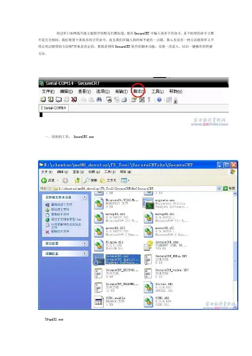
用过串口加网线升级主板程序的朋友们都知道,要在SecureCRT中输入很多字符命令,各个机型的命令又都不是完全相同,我们要背下来很多的字符命令,而且我们在输入的时候不能有一点错,那么有没有一种方法既简单又不用去死记硬背的方法呢?答案是肯定的,那就是利用SecureCRT软件的脚本功能,实现一次录入,以后一键操作的快捷方法。
一、用到的工具: SecreCRT.exeTftpd32.exe二:工具的配置第一步:将USB串口升级版与电脑连接起来。
此时电脑会识别串口板。
第二步:找到串口板在电脑上的串口号;“右键“我的电脑,点击“管理”选择“设备管理器”---“端口(COM和LTP)”,可以看到此时COM口为COM14,记住后卫配置要用到。
(注意:不同的机器该数字不相同,一定要确认该数值。
此处的COM14只是一个范例)1、SecreCRT.exe的配置,打开SecreCRT.exe后,新建连接,在协议里选择Serial选择Serial后的配置如下:其中的端口是连接USB工具后USB的串口端口、流控制中所有的勾都要去掉!2、网络的配置:使用一根网线将电脑和电视直接连接起来,然后配置计算机的IP地址。
本地连接中的IP地址需要重新配置,请按如下配置:(LAN为本地连接)3、FTP的配置,打开Tftpd32.exe后,点击Browse选择升级程序所在文件夹,如下图所示。
配置完后,该软件不要关闭。
(本教程以TCL MS28机芯为例)三、烧写步骤1、将串口与网线连接好机器,打开SecreCRT.exe,机器上电的同时按紧回车键,(如果电视是上电待机,需要将电视使用遥控器开机时,也要一直按着回车键不放)会出现<># 的命令行这个时候就进入到我们最关键的时候了,前面的内容有些课件已经介绍过,现在进入正题:当出现<># 的命令行后,我们点击“脚本---开始录制脚本”接着就是按照正常的方法输入各条命令设置IP地址,在串口命令中输入:Set ipaddr 10.120.29.55Set serverip 10.120.29.5Saveenv设置FLASH,在串口命令中输入:mstar auto.txt回车输入完命令以后程序自动执行抄写命令,如下图我们已经执行完所有的手动操作命令了,这时我们就可以停止录制脚本了,具体方法是点击“脚本---停止录制脚本” 如下图:点击完“停止录制脚本”时,会弹出一个“另存为”对话框,是询问我们把录制的脚本存储的位置以及名称(我个人认为不要存储在C盘以及名称最好按机芯名称存储)。
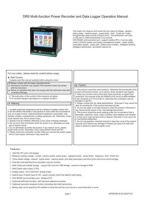
⊙ 320*340 TFT color LCD display.⊙ Measure 3 phase voltage , current , reactive power ,active power , apparent power , power factor , frequency , Kwh , KvarH ect.⊙ Three phase voltage , ampere , active power , reactive power ,and other parameters real time record and curve record storage ⊙ Total Kwh and total KvarH accumulation memory function .⊙ Both inside and outside storage , support SD card and USB storage , maximum storage is 8GB ⊙ With 2 alarm relay output ( 2 DO)⊙ Analog output : one 4-20mA DC analog output.⊙ Switch input :4 switch input S1-S4 , used in remote control the electric swith status.⊙ With RS485 communication port , Modbus RTU⊙ Optional tariff rate function, with demand statistics function.⊙ Optional harmonic analysis funtion (including the total harmonics).⊙ Backup data can be opened by PC software to show the real time curve record or show information in excel.Features:DR9 Multi-function Power Recorder and Data Logger Operation ManualThis meter can measure and record the true value of voltage , ampere , active power , reactive power , power factor , Kwh , KvarH ect. It also can generates various kinds of report forms . The parameters can copy to SD card or USB automatically or by manual .With RS485 communication port , support modbus RTU. It can be widly used in SCADA system and energy management system , power station automation system , power grid , estate power monitor , intelligent building ,intelligent switchboard and switch cabinet ectInstrument accessoriesPower Consumption ≤8VAFrequency 40~60Hz 、 Accuracy:0.1HzWorking Environment work temperature:-10℃~+45℃, Humidity <85%RH no condensation ,Work temperature limit:-25℃~+55℃, Storage temperature:-25℃~+70℃, Analog Output Alarm Output 4 On/Off output, 250VAC/3A or 30V DC/5A Dimension 96W×96H×100Lmminput VS power: AC 2000V, Power VS relay :AC 2000V ,Power VS transmition output:DC 2000V ,RS485 port ,isolated low voltage or I/O: DC 600VTechnical ParametersConnection 3 phase 3 wires, 3 phase 4 wiresVoltage Range AC 3x57.7V / 3X220V (note: Direct input volt: L-N: 0~600V, L-L: 0~1000V)Voltage Overload Continuous: 1.2 times Instantaneous: 2 times/10SVoltage Consumption <1VA (each phase)Voltage impedance ≥300KΩVoltage Accuracy RMS measurement , Accuracy : 0.5AC 0.025 ~ 5ACurrent Range Current Overload Continuous: 1.2 times Instantaneous: 4 times/10SCurrent Consumption <0.4VA (each phase)Current impedance <20m ΩCurrent Accuracy RMS measurement , Accuracy : 0.5Energy Active energy accuracy 0.5 / Reactive energy accuracy 1.Power Active power/Reactive power/Apparent power, accuracy: 0.5 Display TFT color display Power Supply AC/DC 100 ~ 240VOutput Digit InterfaceRS-485 Modbus-RTU Protocol1 transmition output, 4-20mA DC Load<400ΩAnti-jammingElectrostatic interference resistance ability :IEC61000-4-2,Level 2Radiation anti-jamming capacity: IEC61000-4-3,Level 3Fast transient pulse interface :IEC61000-4-4,Level 4Surge immunity (1,2/50us-8/20us ):IEC61000-4-5,Level 4Isolation&punctureInsulationInput/output/power supply to Meter cover >5MΩDimension and Mounting SizeSide size Hole sizeMake the lock button aim at adjustment screwA B CNCurrent input via CT A B CDO2AL2AC/DC DO1AL1POWER Wire ConnectionNote: 1. For voltage input connection terminal,bracket terminals (Ua) (Uc) (Ub) shows 3 phase 3 wire connection method, 2. Current input is current input terminal ,all the inputs and outputs must be coherentModel 1: (3pcs CT) 3 phase 4 wire working modeModel 2: (2pcs CT): 3 phase 3 wire working mode Current inputVoltage inputVoltage direct inputVoltage input via PTCurrent inputCurrent input via CT Voltage inputVoltage direct inputVoltage input via PTExplanation :A. Voltage input: Input voltage should not be higher than the rated input voltage of meter, otherwise a PT should be used.B. Current input: Standard rated input current is 5A. A CT should be used when the input current is bigger than 5A. If some other meters are connected with the same CT , the connection should be serial for all meters.C. Please make sure that the input voltage is corresponding to the input current, they should have the same phase sequence and direction,otherwise data and sign error may occur (power and energy).D. The connection mode of meter which is connected to power network should depend on the CT quantity. For 2pcs of CT, it should be 3 phase 3 wire connection. For 3pcs of CT, it shoud be 3 phase 4 wire connection.E. Please pay high attention on the difference between 3 phase 3 wire and 3 phase 4 wire connection , becasue wrong connection may lead to incorrect calculation of power factor, power and energy .Panel IndicationUSB portSD cardPage Guide。
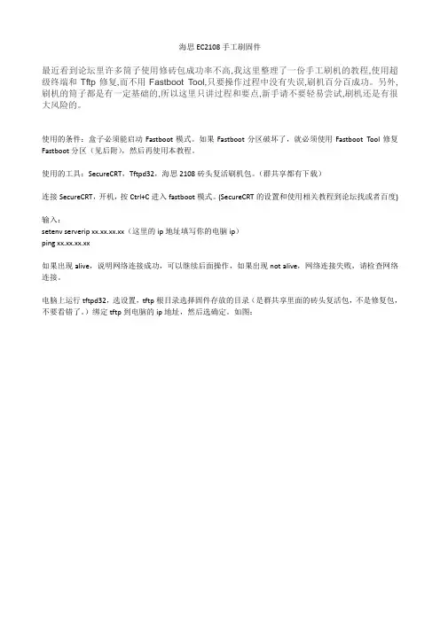
海思EC2108手工刷固件最近看到论坛里许多筒子使用修砖包成功率不高,我这里整理了一份手工刷机的教程,使用超级终端和Tftp修复,而不用Fastboot Tool,只要操作过程中没有失误,刷机百分百成功。
另外,刷机的筒子都是有一定基础的,所以这里只讲过程和要点,新手请不要轻易尝试,刷机还是有很大风险的。
使用的条件:盒子必须能启动Fastboot模式。
如果Fastboot分区破坏了,就必须使用Fastboot Tool修复Fastboot分区(见后附),然后再使用本教程。
使用的工具:SecureCRT,Tftpd32,海思2108砖头复活刷机包。
(群共享都有下载)连接SecureCRT,开机,按Ctrl+C进入fastboot模式。
(SecureCRT的设置和使用相关教程到论坛找或者百度)输入:setenv serverip xx.xx.xx.xx(这里的ip地址填写你的电脑ip)ping xx.xx.xx.xx如果出现alive,说明网络连接成功,可以继续后面操作,如果出现not alive,网络连接失败,请检查网络连接。
电脑上运行tftpd32,选设置,tftp根目录选择固件存放的目录(是群共享里面的砖头复活包,不是修复包,不要看错了。
)绑定tftp到电脑的ip地址,然后选确定。
如图:以下每一行为一条命令,复制一条,回到SecureCRT,粘贴后回车运行,直到最后一条完成。
重要:以下红色标注的命令,只有刷过安卓固件需要修复的才运行。
请不要轻易尝试。
mw.b 82000000 ff 100000tftp 82000000 fastboot.binnand erase 0 100000nand write 82000000 0 $(filesize)重要:以上红色标注的命令,只有刷过安卓固件需要修复的才运行。
请不要轻易尝试。
mw.b 82000000 ff 100000tftp 82000000 partition.binnand erase 100000 100000nand write 82000000 100000 $(filesize)mw.b 82000000 ff 600000tftp 82000000 boot1.binnand erase 200000 600000nand write 82000000 200000 $(filesize)mw.b 82000000 ff 4000000tftp 82000000 app.yaffsnand erase 800000 4000000nand write.yaffs 82000000 800000 $(filesize)mw.b 82000000 ff 100000tftp 82000000 logo.imgnand erase 4800000 100000nand write 82000000 4800000 $(filesize)mw.b 82000000 ff 100000tftp 82000000 param1.binnand erase 4900000 100000nand write 82000000 4900000 $(filesize)mw.b 82000000 ff 100000tftp 82000000 playlist.binnand erase 4a00000 100000nand write 82000000 4a00000 $(filesize)mw.b 82000000 ff 6c00000tftp 82000000 swfs.yaffsnand erase 9400000 6c00000nand write.yaffs 82000000 9400000 $(filesize)所有操作完成,刷机成功。
PXE网络启动WINPE及网络GHOST
多年前还在一家电脑公司工作时,经常大批量安装操作系统,使用网络GHOST组播方式克隆系统,一次可克隆20-30台机器,速度也非常快,非常方便。
而且在维护系统时,没有启动光盘和U盘时,也是一种不错的解决办法。
现将相关软件和使用的工具盘更新后上传上来,供用得着的朋友共享。
使用方法:
1、下载附件解压到硬盘;
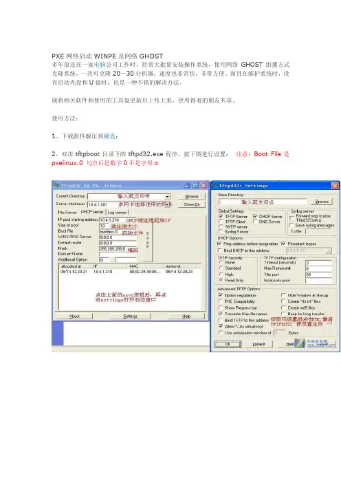
2、双击tftpboot目录下的tftpd32.exe程序,按下图进行设置;注意:Boot File是pxelinux.0 句点后是数字0不是字母o
3、客户端选择从网络启动(需要网卡支持PXE启动),启动菜单如下,选择MaxDOS7.1;
4、选择手动网络刻隆,接下来需正确选择你的网卡型号,安装相应驱动;
5、选择3.启动GHOST
6、在服务器端双击解压目录下的GhostSrv11.exe,启动GHOST服务器,进行下图设置(新硬盘进行分区可使用磁盘分区GHOST映像文件);
7、在客户端按下图设置;
8、输入组播会话名,会话连接成功后进行GHOST目的磁盘或分区的选择,然后等待服务器端发送数。
在第6步中如果设置了客户端连接数,当客户端连接数达到设置数就会自动
开始网刻,否则需手动开始发送数据。
下图是通过PXE启动WINPE
下图是启动的WINPE桌面。
TFTP(Trivial File Transfer Protocol,简单文件传输协议)是TCP/IP协议族中的一个用来在客户机与服务器之间进行简单文件传输的协议,提供不复杂、开销不大的文件传输服务。
TFTP承载在UDP上,使用UDP 67端口,提供不可靠的数据流传输服务,不提供存取授权与认证机制,使用超时重传方式来保证数据的到达。
与FTP相比,TFTP的大小要小的多。
首先,我们要先在自己的机上运行tftp服务器,这里推荐使用aftp,它比大家常用的tftpd32好多了,因为它可以方便的设置文件的目录和显示传输速率和进度,这样我们就可以随时了解进程。
当你第一次使用时,先进行一些设置,主要是超时时间,最大连接要设置大一些,文件夹选择你的软件存放的目录,一般把aftp放到你的软件的当前目录,这里的“."就表示当前目录。
其他设置默认就可以了。
其次,tftp的用法一、上传:格式:tftp -i 你的IP get 要上传文件存放位置(可以省略)比如tftp -i 202.116.191.200 get findpass.exe二、下载:格式:tftp -i 你的IP put 要下载文件存放位置(可以省略)比如tftp -i 202.116.191.200 put good.rar注意点:1、tftp在运行中不得断开连接。
2、文件的默认存放位置就是tftp目录。
3、可以在任何对方的命令行使用tftp,如:跟在对方IP后的浏览器地址栏里(详细说明请参考U漏洞的贴子)、SQLEXEC的command输入行等等位置。
4、tftp默认属性是上传和下载的时候采用覆盖不提示的方式。
5、tftp上传的文件可能会加上只读属性,请上传完全毕后检阅Tftp向运行平凡文件传输协议(TFTP) 服务或daemon 的远程计算机(尤其是运行UNIX 的计算机)传输文件或从运行平凡文件传输协议(TFTP) 服务或daemon 的远程计算机(尤其是运行UNIX 的计算机)传输文件。
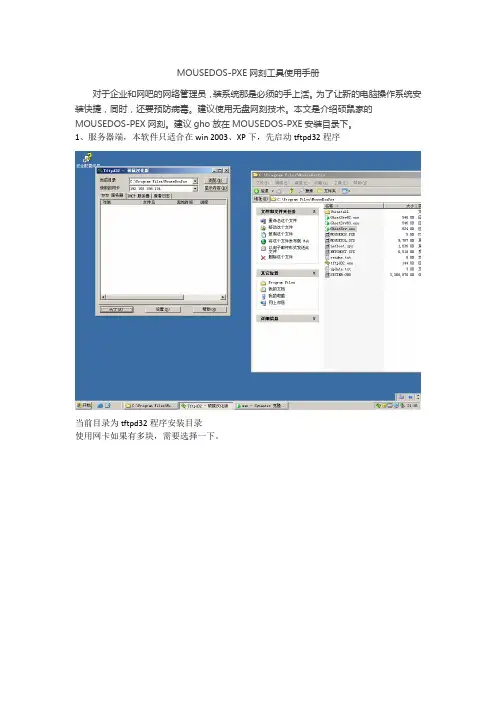
MOUSEDOS-PXE网刻工具使用手册
对于企业和网吧的网络管理员,装系统那是必须的手上活。
为了让新的电脑操作系统安装快捷,同时,还要预防病毒。
建议使用无盘网刻技术。
本文是介绍硕鼠家的MOUSEDOS-PEX网刻。
建议gho放在MOUSEDOS-PXE安装目录下。
1、服务器端,本软件只适合在win 2003、XP下,先启动tftpd32程序
当前目录为tftpd32程序安装目录
使用网卡如果有多块,需要选择一下。
设置DHCP服务器,注意设置前,需要静态本机IP地址。
根据本机地址设置,最好设置同一网段的地址。
点软件下设置,将起始路径设置好。
TFTP高级选项设置如图。
再点GhostSrv.exe,启动它。
客户端:
使用网卡启动,出现硕鼠万能网络克隆向导。
向导移动确认【●】,使用键盘上shift+空格。
按照服务器端设置来设定。

赫思曼交换机使用Tftpd32软件升级步骤¾软件准备安装Tftpd32软件(在随机Manual CD中的Freeware文件夹中Tftpd32有安装文件Tftpd32‐3.25‐setup)一、TFTP服务器的配置安装结束后桌面会出现图标,点击运行后。
z Current Directory:服务器的服务目录。
z Server interface :服务器IP,一般是本机IP地址,软件会自动测试。
如何设置Current Directory:点击Settings,公司:北京中达信泰 地址:北京市海淀区上地十街辉煌国际1号总机:010‐59813149/50转0设置Base Directory 目录即为服务器服务目录,其他参数默认。
点及OK后,需要重新启动程序设置方起作用。
下图为汉化界面:公司:北京中达信泰 地址:北京市海淀区上地十街辉煌国际1号总机:010‐59813149/50转0服务目录设置好后,开启软件即可提供文件传输服务。
二、TFTP客户端使用方法¾方法一1、在“开始→运行”中输入“CMD”并回车,或是从附件中选择“命令提示符”,然后输入 tftp回车2、传输命令格式:下载:tftp –i tftp‐server get source‐file dest‐filetftp‐server tftp服务器的IP地址,也就是Server interface设置的IP地址source‐file 需要从tftp服务器上下载的文件名称dest‐file 下载完成后保存时的文件名,可以指定保存路径tftp –i get命令用来从TFTP服务器上下载文件,TFTP无法在客户端上切换或者指定服务器的工作目录,如需要进入其他目录,只能在TFTP服务器软件上进行修改,并且重新登录。
上传:tftp –i tftp‐server put source‐file dest‐file公司:北京中达信泰 地址:北京市海淀区上地十街辉煌国际1号总机:010‐59813149/50转0tftp‐server TFTP服务器的IP地址,也就是Server interface设置的IP地址source‐file 需要上传到TFTP服务器上的文件名称dest‐file 上传到TFTP服务器后保存时的文件名。
tftpd32使用1. 引言:TFTPD32是一款开源的Trivial File Transfer Protocol (TFTP)服务器软件,它允许在网络上进行文件传输。
TFTP是一个简单的文件传输协议,通常用于在计算机之间传输小文件,如配置文件和固件更新。
TFTPD32具有易于使用的界面和丰富的功能,使其成为网络管理员和开发人员的首选工具。
本文将介绍TFTPD32的安装、配置和使用方法。
2. 安装TFTPD32:首先,您需要从TFTPD32的官方网站(/)下载软件的最新版本。
安装程序非常简单,只需按照向导的指示进行操作即可完成安装。
3. 配置TFTPD32:一旦安装完成,您可以通过打开TFTPD32应用程序开始配置。
在首次运行时,您将看到一个包含所有配置选项的窗口。
下面是几个重要的配置选项:3.1 服务器根目录:在TFTPD32中,您需要指定一个服务器根目录,该目录将用于存储您要传输的文件。
您可以在“基础设置”选项卡中设置服务器根目录。
请确保该目录拥有正确的读写权限。
3.2 IP地址和端口:您可以在“基础设置”选项卡中指定服务器应该使用的IP地址和端口。
默认情况下,TFTPD32将使用本地计算机的IP地址和69端口。
如果您需要更改IP地址和/或端口,只需在相应字段中输入新值即可。
3.3 DHCP服务器:TFTPD32还可用作DHCP服务器,允许您为连接到网络的设备提供自动分配的IP地址。
您可以在“DHCP设置”选项卡中配置DHCP服务器。
确保在启用DHCP服务器之前了解和遵守网络的相关政策和要求。
4. 使用TFTPD32:配置完成后,您可以开始使用TFTPD32来传输文件了。
以下是一些常见的用例:4.1 从服务器下载文件:要从TFTPD32服务器下载文件,您需要知道服务器的IP地址和要下载的文件名。
使用TFTP客户端工具(如TFTP客户端或TFTP命令行实用程序),连接到服务器并下载文件。
4.2 上传文件到服务器:要将文件上传到TFTPD32服务器,您需要知道服务器的IP地址、目标文件名和本地文件的路径。
1、将预装的系统iso镜像进行解压;
2、将系统镜像文件里面的image文件下的的pxeboot文件提取出来(针对的是red hat Linux;将initrd.img和vmlinuz拷贝到tftpd32文件下的自建文件夹)(suse里面是boot->x86_64->loader文件下的initrd和linux)。
3、fttpd32的配置:
4、创建虚拟机/将自己的笔记本用网线和服务器连接
在创建虚拟机的时候注意将网卡网络连接设置为自定义:特定虚拟网络;并笔记本的VMware Network Adapter VMnet1网卡设置其IP地址。
注意:如果是在虚拟机上装系统时,请将其他网卡禁掉。
若果是在给实体服务器装系统,就给自己的有线网卡配上IP地址。
5、接下来就是配置filezilla server了(在安装了filezilla server,桌面一般会只有一个FileZilla
Server Interface程序图标,在安装路径里将FileZilla server快捷到桌面,在开启服务的顺序是先启动服务FileZilla server再点击FileZilla Server Interface进行配置。
)
先是添加一个用户users(为了方便通常添加anonymous);
再者就是添加需要上传安装的系统的路径,也就是前面要求解压的系统镜像。
现在就是等待开机或者开启虚拟机了,安装系统。
Copyright 2012 © Embedded Artists AB3.2 inch QVGA TFT Color LCDUser’s GuideVersion 1 & 2Give graphics and color to your application!Embedded Artists ABDavidshallsgatan 16SE-211 45 MalmöSweden************************Copyright 2005-2012 © Embedded Artists AB. All rights reserved.No part of this publication may be reproduced, transmitted, transcribed, stored in a retrieval system, or translated into any language or computer language, in any form or by any means, electronic, mechanical, magnetic, optical, chemical, manual or otherwise, without the prior written permission of Embedded Artists AB.DisclaimerEmbedded Artists AB makes no representation or warranties with respect to the contents hereof and specifically disclaim any implied warranties or merchantability or fitness for any particular purpose. Information in this publication is subject to change without notice and does not represent a commitment on the part of Embedded Artists AB.FeedbackWe appreciate any feedback you may have for improvements on this document. Please send your comments to ***************************.TrademarksAll brand and product names mentioned herein are trademarks, services marks, registered trademarks, or registered service marks of their respective owners and should be treated as such.Table of Contents1Document Revision History4 2Introduction5 2.1Features5 2.2Version 1 vs. Version 25 2.3ESD Precaution6 2.4General Handling Care6 2.5CE Assessment6 2.6Other Products from Embedded Artists6 2.6.1Design and Production Services6 2.6.2OEM / Education / QuickStart Boards and Kits7 3Design Description8 3.1Backlight Control8 3.2On-board LCD Controller, display version 28 3.3On-board touch screen Controller, display version 29 3.4On-board LCD Controller, display version 19 3.5Interface (pin description)10 3.6Optimum Viewing Angle13 3.7Connecting version 2 to OEM Base Board < v1.514 4Board Mechanical Dimensions161 Document Revision History2 IntroductionThank you for buying Embedded Artists’ 3.2 inch QVGA TFT Color LCD Board based on a LCD from Truly. Sample applications for our NXP LPC2xxx based boards are also provided and can be downloaded from the support page. The 3.2 inch QVGA TFT Color LCD Board will be called the QVGA LCD Board for short in the rest of this document.2.1 FeaturesThe QVGA LCD Board has the following features:∙Optional touch screen interface (available for version 2)∙8-bit or 16-bit parallel interface. Only occupies 2 addresses (i.e., one address pin) or serial 8-bit (SPI-like) interface (max 10 MHz clock)∙Diagonal size: 3.2 inch∙Display technology: TFT∙Display mode: Transmissive∙No of pixels: 240xRGBx320 (QVGA size)∙Supply voltage: 3.0-3.3V∙White LED backlight, with PWM control∙View area: 48.6 x 64.8 mm∙Dot size: 0.2025 x 0.2025 mm∙Operating temperature: -20 to + 70 degrees Celsius∙No of colors: 262K (if 18-bit mode), 65k (if 16-bit mode)∙2x20 pos connector (100 mil spacing) is required to interface the module, plus optional 1x6 pos connector∙Small form factor: 93 x 83 mm2.2 Version 1 vs. Version 2There exist two versions of the display. Version 1 uses a display from one display manufacturer and version 2 uses a display from another manufacturer.The similarities between the versions are:∙Same physical size of display module.∙Same optical features and capabilities.∙Same main 2x20 pos interface connector (100 mil spacing).The differences are:∙Different internal display controllers are used. The programming interface is not identical but very similar. A reference software driver exists that supports both versions simultaneous.∙Version 2 of the display module has a touch screen option.∙ A 6 pos extra interface connector has been added beside the main 2x20 pos interface connector. This extra connector carries signals for touch screen interface and some extrasignals for direct RGB-control of display (useful when interfacing the LPC2478 MCU from2.3 ESD PrecautionPlease note that the QVGA LCD Board comes without any case/box and allcomponents are exposed for finger touches – and therefore extra attention mustbe paid to ESD (electrostatic discharge) precaution.Make it a habit always to first touch a ground pin/hole for a few secondswith both hands before touching any other parts of the boards. That way,you will have the same potential as the board and therefore minimize the risk forESD.Note that Embedded Artists does not replace boards that have been damaged by ESD.2.4 General Handling CareHandle the QVGA LCD Board with care. The boards are not mounted in a protective case/box and are not designed for rough physical handling. Connectors can ware out after excessive use. The QVGA LCD Board is designed for prototyping use, and not for integration into an end-product.Do not exercise excessive pressure on the LCD glass area. That will damage the display. Also, do not apply pressure on the flex cables connecting the LCD/touch screen. These are relatively sensitive and can be damaged if too much pressure is applied to them.Note that Embedded Artists does not replace boards where the LCD has been improperly handled.2.5 CE AssessmentThe QVGA LCD Board is CE marked. See separate CE Declaration of Conformity document.The QVGA LCD Board is a class A product. In a domestic environment this product may cause radio interference in which case the user may be required to take adequate measures.EMC emission test has been performed on the QVGA LCD Board when connected to Embedded Artists base boards. Connecting the board to other devices may alter EM C emission. It is the user’s responsibility to make sure EMC emission limits are not exceeded when connecting the board to other devices.Due to the nature of the QVGA LCD Board – an evaluation board not for integration into an end-product – fast transient immunity tests and conducted radio-frequency immunity tests have not been executed. Externally connected cables are assumed to be less than 3 meters. The general expansion connectors where internal signals are made available do not have any other ESD protection than from the chip themselves. Observe ESD precaution.Note that the QVGA LCD Board can also be considered to be a component if integrated into another product. The CE mark on the QVGA LCD Board cannot be extended to include the new (user created) product. It is the user’s responsibility to make sure EMC emission limits are not exceeded and CE mark the final product.2.6 Other Products from Embedded ArtistsEmbedded Artists have a broad range of LPC1000/2000/3000/4000 based boards that are very low cost and developed for prototyping / development as well as for OEM applications. Modifications for OEM applications can be done easily, even for modest production volumes. Contact Embedded Artists for further information about design and production services.2.6.1 Design and Production ServicesEmbedded Artists provide design services for custom designs, either completely new or modification to existing boards. Specific peripherals and I/O can be added easily to different designs, for example,broad, and long, experience in designing industrial electronics in general and with NXP’sLPC1000/2000/3000/4000 microcontroller families in specific. Our competence also includes wireless and wired communication for embedded systems. For example IEEE802.11b/g (WLAN), Bluetooth™, ZigBee™, ISM RF, Ethernet, CAN, RS485, and Fieldbuses.2.6.2 OEM / Education / QuickStart Boards and KitsVisit Embedded Artists’ home page, , for information about other OEM / Education / QuickStart boards / kits or contact your local distributor.3 Design DescriptionThis chapter describes the hardware design of the QVGA LCD Board.3.1 Backlight ControlWhite LEDs are used as backlight on the display. The LED current is set to 15 mA. A step-up DC/DC converted is used to generate a constant LED current. The switching frequency is fixed to 1.2 MHz. The intensity of the backlight (i.e., the white LEDs) is varied by varying the LED current. There are two ways to very the LED current between 0-15 mA. A digital PWM signal is needed with the same logic levels as the power supply (typically 3.3V).∙Modulate the shutdown pin of the DC/DC converter (signal LED_SHDN). A low input signal turn off the DC/DC converted and a high level activate it. A high duty cycle on the PWM signal equals high intensity.∙Modulate the current set pin of the DC/DC converter (signal LED_PWM). A low input signal increase the LED current and a high level reduce it. A high duty cycle on the PWM signalequals low intensity.The frequency of the modulation (PWM) signal should ideally be in the 5-10 kHz region.3.2 On-board LCD Controller, display version 2The display has an embedded controller, SSD1289 from Solomon Systech. This controller chip has 1.3 Mbit embedded display RAM, which is enough for storing a complete 320xRGBx240 picture with 18 bit color depth.There are a couple of interface alternatives to this controller. Either 18-bit, 16-bit, 9-bit or 8-bit parallel interface or a serial interface. There are 4 pins that are used to configure the interface. The table below lists the different options. L is statically tied to low logic level and H is statically tied to high logic level.If the parallel interface is selected, there are two different interface types; either 6800 or 8080 style. See datasheet for details about timing and how the different control signals are used.If a serial interface is used, see the datasheet for details about timing and how the different control signals are used. Note that maximum clock frequency is 13 MHz.3.3 On-board touch screen Controller, display version 2The touch screen controller used is TSC2046 from Texas Instruments. This chip has a SPI interface and shares the SI, SO, SCK pins in the main interface connector, with the LCD controller. Pin 45 must however be low (TSC2046 chip CS#) in order to communicate with the touch screen controller. See TSC2046 datasheet for details about the serial interface.3.4 On-board LCD Controller, display version 1The display has an embedded controller, IS2102B from ISRON. This controller chip has 1.3 Mbit embedded display RAM, which is enough for storing a complete 320xRGBx240 picture with 18 bit color depth.There are a couple of interface alternatives to this controller. Either 16-bit or 8-bit parallel interface or a serial interface. There are 6 pins that are used to configure the interface. The table below lists the different options. L is statically tied to low logic level and H is statically tied to high logic level.If the parallel interface is selected, there are two different interface types. The configuration pin C86 is used to select between the i86 interface and the M68 interface. See datasheet for details about timing and how the different control signals are used.If a serial interface is used, see the datasheet for details about timing and how the different control signals are used. Note that maximum clock frequency is 10 MHz.3.5 Interface (pin description)The table below describes the 40 pin interface to the QVGA LCD Module. A 2x20 pos (100 mil spacing) header connector facing down is used. See datasheet for details about interface timing.On display version 2 a new extra 1x6 pos (100 mil spacing) header connector facing down exists. See datasheet for details about interface timing.The picture below illustrates the pin numbering of the QVGA LCD Module .Figure 1 - 3.2 inch QVGA TFT Color LCD Board Pin NumberingPin2Pin403.6 Optimum Viewing AngleOptimum viewing angles are as illustrated below.Figure 2 - 3.2 inch QVGA TFT Color LCD Board Optimum Viewing Angle3.7Connecting version 2 to OEM Base Board < v1.5Version 1.5 and above of the OEM Base Board has direct connectors for all 46 positions in theinterface connector. Version 1.4 and below do not have the 6 extra positions (pos 41-46). These have been added for version2 of the display.The touch screen controller can still be accessed with just one extra wire, from pin 45 on the display module to P0.16 on the OEM Base Board. P0.16 is used for chip select of the touch screen controller. Other pins work just as well, but P0.16 is used on v1.5 and above of the OEM Base Board.Figure 3 - 3.2 inch QVGA TFT Color LCD Board Pin 45Simply connect a wire from pin 45 on the display module to P0.16 on the OEM Base Board. Figure 4 and 5 below illustrate the wire connection. Also note that the three SPI jumpers must be inserted, see Figure 4 for details.Figure 4 – Picture of Wire to Pin 45 on Display Module Figure 5 – Wire to p0.16 on OEM Base Board Three SPI jumpers must be inserted since communication with touch screen controller is via SPI.4 Board Mechanical DimensionsFigure 6 below contains a drawing of the board that includes mechanical measures. Four 4.3 mm grounded mounting holes are used.Figure 6 - 3.2 inch QVGA TFT Color LCD Board Mechanical Dimensions70 mm 93 mm80.0 mm 6.5 mm。
开发板烧录教程开发板型号:FL2440烧录⼯具: J-Link串⼝⼯具:340调试终端:secureCRT下载⼯具:tftpd32烧录前:串⼝连接开发板,在secureCRT上快速链接:1)协议:Serial ;2)在设备管理器选择端⼝进⾏选择3)波特率:115200,数据位:8 ,奇偶校验: none ,停⽌位:04)不选择流控烧录要使⽤的⽂件:烧录⽂件说明:--------------------bootstrap-s3c2440.binbootstrap⽂件是郭⼯⽤汇编写的⼀段代码,主要⽤来初始化CPU外部的SDRAM;在烧录时,该程序需要使⽤j-link下载到0x0(CPU内部SRRAM)地址上去运⾏,另外此程序不需要烧录到Nandflash上。
u-boot-s3c2440.bin--------------------u-boot就相当于电脑的BIOS程序,该程序⽤来烧录/启动Linux系统等。
在运⾏完bootstrap后,我们需要使⽤j-link将它加载到0x33f80000(CPU外部SDRAM)中去运⾏,当他在内存中运⾏起来后,再使⽤nand write命令将他烧录到nandflash的0地址上去;linuxrom-s3c2440.bin--------------------linuxrom是linux系统⽂件,我们需要在u-boot运⾏时,使⽤tftp命令下载到SDRAM的0x30008000地址上,然后再使⽤nand write命令将其烧录到nandflash的0x100000地址上,记得flash再写之前⼀定要先使⽤nand erase命令擦除。
s3c2440_apps.apm--------------------该程序为FL2440上的应⽤程序,包括系统配置,WiFi使⽤,3G/GPRS拨号,数据库,web server,MP3/MP4播放器程序等;修改⽹卡IP地址和MAC地址在:/apps/etc/network/ifcfg-eth0J-link commander的连接,在开发板上插上J-link ,如果没有J-link驱动请先安装,在开始菜单-程序-SEGGER-J-link commander 双击打开连接正确后接着进⾏J-link命令操作:J-link 加载u-boot命令h 停⽌CPU中正在执⾏的程序,如果没有停下,可以多按⼏次hspeed 12000 设置J-link调试速度为12Mloadbin E:\Baiduyun\bootstrap-s3c2440.bin 0 加载bootstrap程序到CPU内部的4K SRAM中运⾏setpc 0 让PC寄出去指向SRAM的起始地址,该地址放的是刚才下载的bootstrap程序g 开始执⾏bootstrap程序,该程序⽤来初始化外部扩展的64M SDRAM,地址空间为0x3000 0000~(0x3000 0000+64M)h 停⽌bootstrap程序的执⾏,如果没有停下,可以多按⼏次hloadbin E:\Baiduyun\u-boot-s3c2440.bin 0x33f80000 将u-boot加载到SDRAM的0x33f80000setpc 0x33f80000 使PC寄存器指向0x33f80000,即u-boot程序的第⼀条代码g 开始执⾏u-boot程序这样u-boot就下载到开发板的内存上并可以运⾏了。
平时我们传送文件时,往往是通过FTP、邮箱或是QQ等。
但事实上,我们并非整天在传送文件,因而架个FTP服务器有点小题大做了,而用QQ传送又经常会受防火墙的制约,至于邮箱,附件大小就那么点,常常不够用,这时我们可以尝试另一种传送方式——Tftp。
Tftp全称为Trivial File Transfer Protocol,中文名叫简单文件传输协议。
大家可以从它的名称上看出,它适合传送“简单”的文件。
与FTP不同的是,它使用的是UDP的69端口,因此它可以穿越许多防火墙,不过它也有缺点,比如传送不可靠、没有密码验证等。
虽然如此,它还是非常适合传送小型文件的。
通过Ttfp传送文件时,需要设置和定制服务端及客户端。
比如我想从朋友的机器上下载文件,那就需要先把他的机器做成Tftp服务器,然后用我机器的客户端进行下载。
Windows 2000之后的操作系统自带有客户端,所以整个传送过程,事实上忙的是对方!
下面我以从朋友机器上下载一些图片为例来说明一下Tftp的使用过程。
1.设置TFTP服务器
将朋友的机器设置为TFTP服务器。
首先叫你的朋友把Tftpd32下载下来并解压(他可能很郁闷哦),然后打开Tftpd32(如图1),这时你朋友的机器就是一个Tftp服务器了。
软件默认Tftpd32的保存目录即为下载目录,换句话说,你要下载的文件需要放在Ttfpd32服务器的保存目录下才能被客户端下载。
更改Tftpd32下载目录的操作方法为:点击右上角的“Browse”,然后选择要下载的文件的保存目录。
不过经此设置后,以后你要想从你朋友机器上下载文件,就要让他先把文件放在更改后的下载目录里,而不是Tftpd32的保存目录了。
如果你朋友搞不清当前下载目录下到底有哪些文件,可以让他点击右上角的“Show Dir”进行查看(如图2)。
提示:
a.要进行更人性化的设置,如下载的人数、下载端口等,可以点击
“Settings”按钮;然后在“Tftp port(Tftp端口)”、“Max Retransmit(最大连接数)”等项上填写相应值,这里建议不要更改端口。
b.如果你要传的文件比较多,可以先让你朋友将它们打包,这样传起来比较方便。
2.传送文件
对方忙了这么久,下面也该自己出手了。
由于朋友把我要的图片都打包了(命名为:pictures.rar),所以我要做的就是把pictures.rar下载下来,并保存在D盘的“图像资料”目录下,这时有两种方法可以完成。
方法一
在“开始→运行”中输入“CMD”并回车,或是从附件中选择“命令提示符”,然后输入“d:”回车(引号不用输),这样就切换到D盘了,再输入“cd d:\图像资料”并回车,这时切换到了“d:\图像资料”目录,然后输入命令“Tftp -i朋友IP get pictures.rar”。
方法二
上面说的是用命令的方法,下面咱们也试试图形界面的方法。
先下载Tftpd32这个软件(两头都装一个),在“Current Directory”处选择你要保存的路径,这里我选的是“d:\图像资料”;切换到“Tftp Client”,在“Host”处填上朋友的IP,在“File”处填上下载的文件名,这里填的是“pictures.rar’,然后点击“Get”(如图3),一会你就可以在目录下找到文件了。
点“Put”则是把文件传到你朋友Tftpd32的下载目录中。
需要注意的几个问题:
a.文件传送成功与否,你朋友也可以在Tftpd32的“Tftp Server”和“Current Action”这两项中看到。
b.如果想把文件传给你朋友,那么只要把命令换成“Tftp -i朋友IP put pictures.rar”即可。
关于Tftp命令的更多参数,你可以在CMD下输入Tftp进行查看。
不过此时你朋友不能进行上传和下载工作,因为他此时是Tftp的服务端,只有客户端才能进行这些操作。
如果他想把东西传给你,那就需要你做服务端了。
c.用Tftp传送文件时,服务端需有确定的公网IP,如果你朋友在局域网中通过网关上网的话,那就无法传送了。
当然,如果两个人在同一局域网中,用内网的IP也可以传送文件,只是有些多此一举。
d.Windows 98系统可以当服务端,但客户端一定要是Windows 2000或是Windows XP等有Tftp命令的系统。
OK,Tftp传送方式就介绍到这儿,以后如果你遇到因为防火墙等原因不能通过QQ传送文件时,不妨试试Tftp。