KK中文说明书_Rev05
- 格式:pdf
- 大小:683.79 KB
- 文档页数:4

稱重顯示控制器KM05說明書2010年6月版●使用前請仔細閱讀本產品說明書●請妥善保管本產品說明書,以備查閱創唯實業有限公司目錄1.0 概述 (1)1.1主要特點 (1)1.2技術指標 (1)1.2.1 負載能力 (1)1.2.2 性能 (1)1.2.3 電源 (1)1.2.4 溫度和濕度 (2)1.2.5 外形尺寸(尺寸單位為毫米) (2)2.0 安裝 (2)2.1儀錶固定 (2)2.2電路連接 (3)2.2.1 後視圖 (3)2.2.2 電源連接 (3)2.2.3 荷重元連接 (3)2.2.4 串列口通訊線連接 (3)2.2.5 類比輸出連接 (4)2.2.6 繼電器控制輸出 (4)3.0 顯示面板 (5)4.0 重量標定 (5)4.1參數確定 (5)4.2標定步驟 (6)5.0 類比輸出類型選擇與調整 (7)5.1選擇輸出類型 (7)5.2選擇類比輸出對應的重量範圍 (7)5.3調整類比輸出的底端與頂端 (8)5.4恢復類比輸出的底端與頂端 (8)6.0 儀錶工作參數選項 (9)6.1進入工作參數選項 (9)6.2功能F2選項參數組內容 (9)7.0 繼電器輸出 (9)7.1繼電器輸出設置步驟 (10)8.0 設置串列介面 (10)8.1設置步驟 (10)8.2選擇匯流排方式 (11)9.0 開機自檢資訊 (11)10.0 部分參數快速查看 (11)11.0 錯誤提示資訊 (12)12.0 儀錶的維護 (12)12.1儀錶的常規維護 (12)12.2一般故障排除 (12)附錄通訊協定1-命令方式 (14)資料格式 (14)附錄通訊協定2-連續發送方式1 (16)附錄通訊協定3-連續發送方式2 (17)1.0 概述KM05工業控制領域(或其他需要類比輸出的應用場所)的稱重顯示控制器,集重量顯示與類比信號輸出於一體,前端信號處理採用高精度的24位專用A/D轉換器,類比信號輸出採用16位元的D/A轉換器。

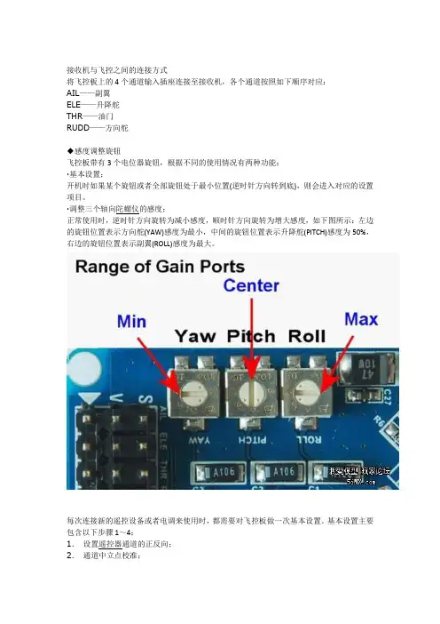
接收机与飞控之间的连接方式将飞控板上的4个通道输入插座连接至接收机,各个通道按照如下顺序对应:AIL——副翼ELE——升降舵THR——油门RUDD——方向舵◆感度调整旋钮飞控板带有3个电位器旋钮,根据不同的使用情况有两种功能:·基本设置;开机时如果某个旋钮或者全部旋钮处于最小位置(逆时针方向转到底),则会进入对应的设置项目。
·调整三个轴向陀螺仪的感度;正常使用时,逆时针方向旋转为减小感度,顺时针方向旋转为增大感度,如下图所示:左边的旋钮位置表示方向舵(YAW)感度为最小,中间的旋钮位置表示升降舵(PITCH)感度为50%,右边的旋钮位置表示副翼(ROLL)感度为最大。
每次连接新的遥控设备或者电调来使用时,都需要对飞控板做一次基本设置。
基本设置主要包含以下步骤1~4:1.设置遥控器通道的正反向;2.通道中立点校准;3.设置陀螺仪修正方向;4.油门行程校准;5.清除所有设置参数(通常无需使用此功能);6.调整陀螺仪感度;7.用遥控器设置启动模式。
请在遥控器上新建一组模型数据(如果遥控器有此功能的话),或者清除所有遥控器设置参数后再设置通道正反向,然后按照上表中的正反参数来调整您的遥控器,如果您的遥控器品牌不在上述表格中,那就需要通过自行测试来确定每个通道的正反状态。
请注意不要打开遥控器的任何混控功能,否则会导致输入飞控的信号不正确。
连接好所有设备后,即可开始进行如下设置。
请在确保所有设置完成前先不要安装螺旋桨,避免受伤!2.通道中立点校准。
中立点校准指的是让飞控的3个通道(除油门外)认准对应遥控器通道的中立点信号,避免因遥控器本身信号的误差导致飞行出现误动作。
-将PITCH旋钮调整到0位置(逆时针旋转):-把遥控器的所有微调调整到中间位置;-系统通电;-等待飞控LED快闪3次,表示进入中立点校准功能;-确认接收机正常收到遥控器信号后继续等待几秒钟;-等待飞控LED慢闪1次,表示识别并保存中立点信号;-信号中立点校准完成,断电并把PITCH旋钮调整到正常位置(一般是中点附近)。
KKK透平机说明书此翻译仅供参考,不承担法律责任。
若有歧义,请以英文为准。
操作手册中文版, Rev.0, 2009.4Mounting and operating instructions安装和操作手册Designation 名称: Turbo compressor unit 涡轮压缩机组Type 型号: 3(2) VRZ 250/430/19 G此翻译仅供参考。
若有歧义,请以英文为准。
操作手册中文版, Rev.0, 2009.4 Page 2 of 79Preface 前言These Mounting and Operating Instructions contain all important instructions for commissioning, operation and maintenance of the 3(2) VRZ 250/430/19 G turbocompressor.本安装操作说明包含3(2) VRZ 250/430/19 G 涡轮压缩机安装调试、操作及维护保养的所有重要信息。
Please read these Mounting and Operating Instructions as well as the LCP operating instructions carefully prior to initial commissioning in order to ensure the safe and efficientuse of the turbo-compressor. 为了保证安全有效的使用涡轮压缩机,请在初次试车之前仔细阅读安装操作说明以及LCP 操作说明。
Furthermore it is important to follow the operating instructions of essential components ofthe unit, such as drive motor, gearbox, oil cooler, oil filter or oil pumps. 另外,遵守重要部件例如驱动电机、齿轮箱、冷油器、滤油器以及油泵的操作说明也是同样重要。

第一章KKS编码及管理软件基础一、KKS(电厂标识系统)应用背景KKS是德国技术委员会(VGB)在上世纪70年代制定的。
随着电厂规模的增大,电厂设备日益复杂,部件日益增多,旧有命名系统越来越难标识;另外为了能在使用者、供货者、制造者、检查员等之间形成统一的认识,这就是KKS诞生的主要原因。
在过去是根据电厂的计划、施工和运行来识别机组及其系统的,结果其命名和分类不尽合理。
由于上世纪60年代初期以前电厂的规模不是很大,旧有命名系统尚能满足当时电厂计划、施工和运行的需要。
随着机组容量的增大,自动化程度的提高以及电厂技术的不断进步和发展,再加上电力生产单位对分类体制的需要,制定统一的现代分类标准已刻不容缓。
于是,1970年成立了由电厂计划人员、生产单位、正规检验员以及其他有关当局参加的工作小组。
经过努力,完成了KKS电厂命名系统。
该系统清楚地标识了机组及其系统,充分考虑了制造厂家、生产单位、检查机构和其他有关当局及机械设计、过程设计、土建工程、电气及热控等专业的需要。
KKS编码系统满足了电厂计划、施工和运行过程中有关各方不论语言和工程中的具体任务是什么,均能统一地绝不含糊地区别和标识自己责任范围以内的电厂部分的要求;同时也适应了电厂规模大、参加方多且分处各处,各单位间的交流和沟通。
KKS电厂标识系统是德国技术委员会(VGB)于1978年以KKS手册的形式发表的。
随着KKS系统在实际应用中出现的不足或疏漏,同时支持和推广KKS的使用,VGB于1983年出版了KKS的第二版本。
随后又于1988年出版了第三版本,1994年出版了第四版,至今KKS使用第四版版本。
KKS的特点1.能区分所有设备和分系统。
2.能清楚地标识所有分系统,采用逐级细分的方法,数据字符具有固定意义。
3.具有足够的代码储备,以备将来电厂工程发展的需要。
4.根据需要,可以选择不同的标识方法。
5.编码长度可变,且不算太长,容易辨认。
6.编码结构层次分明,不易发生混乱或重复。

KKS 说明手册A部分通用应用目录1 状态修改 32 KKS介绍 42.1 设计和种类的数据特性2.2 相关处理识别3 结构和内容的故障等级3.1 故障等级0,全厂“G”以及等级1,“F0”3.2 故障等级1,函数前缀号码3.3 故障等级2,装备单元,A1,A2,AN,A3 3.4 故障等级3,项目B1,B2,BN指数日期(年/月/日)描述A 2009/01/30 第一个问题,通用电气能源标准包括GT,ST和Gen.单元B 2010/12/20 章节1VGB的相关升级。
附录F7d修订。
BPA被用来取代MBJ来实现LCI。
取消原系统编号并将C部分,第3.3.4节的内容替换被取消的第3.5节C 2011/02/11 引用的部分和章节纠正。
3.2章Fn 进行重写和分配。
附录A,miscel.进行了修正。
D 2012/02/08 第1和第2.1章包括安装和位置的标签。
第一章包括现场安装接线和连接盒,基础现场总线设备&基础现场总线段。
电气部分取消,章节3.3.5作为E部分的引用。
附录A被简化,附录B和D完成。
附录C:由于被屏蔽的原因而被替换。
电厂的各建设方和运营方,对于各种零部件的设计和分类的系统标准的遵守是十分必要的。
由于发电厂的规模以及个参与方在位置、信息交流方面存在差异的这个事实的存在,在不久的的将来这些问题将会招致不可估量的花费。
一套系统标准的制定可以使那些电厂中各方不考虑语言和任务的不同明确地,一致地区分他们的责任。
KKS电站识别系统恰恰满足了那些需求。
电站的规划者和运营商采用一套通用的、标准的系统来识别安装和其他部分。
那些关于电站所需的规划,建设和运营所需的数据由此也可被这套系统处理。
本文章参考GE电力系统应用的基于KKS VGB B106e 2007版和B105e 电力技术GmbH 2010第七版的KKS电站识别系统。
英文缩写对照KKS 电站识别系统(Kraftwerk Kennzeichen system)VDEW 德国发电站协会VGB 大型电力企业运营商协会DIN 德国工业标准IEC 国际电工委员会ISO 国际标准化组织ISA 美国仪表协会P&ID 管道和仪表布置图I&C 仪表和控制GE电力系统以及编码系统介绍本篇文章意在总结KKS的结构、内容和应用。

凯隆K K-S500说明书专业发烧机KK-S500说明书目录快速操作指南外观图与功能指示液晶屏显示说明电源使用外接电源安装电池更换电池充电充电须知设置时钟时间使用万年历设置日期设置月份设置年份星期数收听广播电源开关音量调节设置波段波段/米波段频率范围设置中波步进频率调谐电台手动飞梭调谐直接输入电台频率自动调谐手动调谐存储电台存储扫描调出存储电台收听广播的辅助功能提高接收能力—使用天线使用外接天线设置和使用天线的有效方法提高AM接收-同步检波功能远近程开关背光灯使用耳机调频立体声音调模式选择使用锁定功能支撑架使用复位键使用定时功能设置定时1和定时2的时间使用定时1开机功能使用定时2开机功能使用定时1和定时2开机功能使用睡眠关机功能其它信息操作问题与解答二次变频同步检波+二次变频+手动飞梭调谐广播知识什么是同步检波注意事项使用耳机时须注意技术指标功能介绍补充操作说明快速操作指南步骤一:使用电池打开电池盖,将三节五号新电池装入电池仓。
并盖上电池盖。
步骤二:使用外接电源1. 将随机附送的电源适配器插入220V交流电源插座。
2. 在关机状态,将电源适配器与KK-S500外接电源插孔相连。
步骤三:设置时钟时间在关机状态,按任一键点亮背光灯,按[时间设置]键,时间数字闪烁,按[数字]键输入时钟时间的数字,按[频率输入]键确认时钟时间。
步骤四:开机按任一键点亮背光灯,按[电源开关]键打开收音机。
步骤五:音量调节旋转[音量调节]钮,将音量调节到适合收听的位置。
s步骤六:选择波段按[波段转换]键,可选择接收调频、中波、短波波段。
步骤七:存储扫描按一次[存储扫描]键,收音机会自动从该波段的最低端频率开始向上扫描电台,并按顺序保存扫描的电台。
在存储扫描过程中,按一次[存储扫描]键,可中止扫描或扫描完该波段的频率后自动停止。
步骤八:搜索电台的四种方法直接输入电台:按[频率输入]键,频率消失,按[数字]键输入频率,再按[频率输入]键确认。

KK-II培训手册培训资料编写劲拓廖选波一、控制面板紧急挚,设备四角上方各安装一个,按下将关闭所有机械动作。
二、软件安装与应用2.1 控制系统的安装出厂前,所配工控机内的控制系统已安装好。
本系统要求分瓣率在1024*758,如因意外原因导致系统损坏,需重新安装时请按以下步骤进行:打开软件安装文件夹从中选择“setup.exe”文件运行。
(缺省是”E:\SETUP.EXE”) 系统便开始安装软件,出现如下的画面拷贝所需的系统文件。
当拷贝完文件后,系统将显示如下图的画面。
按图中 “确定”将继续下一步安装。
此时系统将显示如下图的画面。
提示用户是否需要改变系统默认的安装目录,建议用户采用系统默认安装目录,若选择“更改目录 “,则可由用户指定软件安装的目录。
选择图标按钮将进入下一步的安装系统将显示如下图画面,要求用户选择软件安装的程序组,系统默认的是“KK Series”,按“继续”将进行下一步安装,。
系统显示如下图系统复制文件进度的安装接口拷贝完文件后将会更新系统,最后出现如下图安装完毕的画面2.2 运行操作软件当计算机进入windows后,系统将自动加载“KK Series”程序,显示下图画面。
此时系统处于自锁状态,用户只有登录系统,才能进行操作。
点击工具栏中“登录系统”图标,将弹出如下图画面,此画面要求用户输入登录系统所需的用户名及相应用户密码,若无用户名及密码将无法进入系统。
缺省用户名是“USER”,对应密码是“123”。
输入正确的用户名及密码,按“确定”。
将显示如下图解锁状态画面,此时用户便可进行正常操作。
在此画面中您可以看到本设备的当前的运行状态,开关状态,报警信息及各种参数设定值,实际值等。
若想开关各个项目只要按下相应的按钮即可进行开关操作。
注意事项:.在此界面中各参数无法直接修改。
2.3 工具栏与菜单栏介绍:以下是本系统的工具栏及菜单栏:5.4.3.3.1 新建选项当选择此选项时,系统将弹出一个新建对话框,显示如下图。
韩版固件 KK 新手调试经验(谢兔哥提醒,重新整理)玩KK5.5大约有一周,已经可以稳稳对尾悬停在10平见方的客厅了。
中间调试也遇到不少问题,总结出来,给入门新人参考,避免犯同样的错误,也希望有更多的新人能享受到玩KK 四轴的乐趣。
实际上玩直机的模型老手根据网上的KK中文资料很快就能正确组装并调试成功,但不少新人是第一次接触模型,立马上手四轴,甚至连浆的正反都不能分辨,本文是针对这样的新人而写,请老手还是轻轻飘过吧,呵呵。
配置:KK 5.5板(110元团购版,需自己焊接)电调 XXD 25A好盈程序版 4个;电机 XXD 2212 KV1000 4个;1045正反桨至少4个,建议买5套,很容易坏。
机架,450尾管和硬盘片自制,建议买成品机架,淘宝上的四轴机架越来越便宜了。
1:烧X还是十字模式?新手还是建议烧十字,比X模式稳定。
X模式是对前2电机、后2电机,或左2电机、右2电机进行平衡控制,对电机电调的一致性要求高,咱XXD电调是最低配置,还是烧十字吧。
飞行方向上,十字比X模式容易辨认。
无论正反桨,安装时,有字那面冲上。
本例以韩国 KR 固件为例,版本1.4-1.7基本都一样2:安装电机电调。
4个电机位置顺序,旋转方向一定要按照KK 中文说明进行安装,这样方便以后调试。
电调最好安装在靠近螺旋桨桨尖处,有助于电调散热。
电机和电调可直接锡焊连接,但事先要接到接收机上弄清旋转方向再焊好套热缩管。
也可焊接香蕉插头后再连接,方便改变旋转方向。
(调换电机任意两根线,可改变旋转方向,有的电调支持编程模式中设定转向,请仔细看电调调试说明书)3:激活KK板。
按照资料介绍,连接好接收机和四个电调,其中3个电调接头的红线,即5V供电,要用针从插接头上挑出来,只用一个电调给KK板及接收机供电。
(兔哥提示说,全部接头也可直接插到KK板子上,这是因为多数电调都是线性BEC供电,允许并联供电,对于开关供电的BEC电调,是不允许并联供电的)KK板子上的YAW、PITCH、ROll3个电位计于中间位置,遥控器油门最低,开关打开;四轴电调上电,KK板LED灯闪一下就灭,把方向摇杆向右打到底,停2秒,KK板上的LED灯常亮,表示顺利激活KK板。
KK52 / KK52 Mark I KK102 / KK102 Mark IUSER GUIDEEnglishWHAT’S NEW IN THE MARK I VERSION?New paint work for black and white models, no screen printingof names and logos.KobraTABLE of CoNTENTSSYMBoLS (3)1. INTRoDUCTIoN (4)2. KEY fEATURES (4)3. APPLICATIoNS (4)4. SAfETY INfoRMATIoN (5)5. UNPACKING (6)6. PhYSICAL (6)6.1 KK52 LAYoUT (6)6.2 KK102 LAYoUT (7)7. wIRING (8)7.1 IMPEDANCE SwITCh (8)7.2 CoVERAGE SwITCh (9)8. ACCESSoRIES AND CoNfIGURATIoNS (10)8.1 SUSPENDING fRoM ThE fLY-BAR (10)8.2 hANGING oN ThE wALL (11)8.3 STANDING oN ThE BASE (11)8.4 hoRIZoNTAL CLUSTER (12)8.5 GRoUND LAYING (12)8.6 STANDING oN A KMT SUBwoofER (13)9. SERVICE (14)10. TEChNICAL SPECIfICATIoNS (15)SYMBoLSTh is symbol alerts th e user to th e presence of recommendations about product’s use and maintenance.This symbol alerts the user to the presence of recommendations about the product’s use and maintenance.K-array declares th at th is device is in compliance with applicable CE standards and regulations. Before putting the device into operation, please observe the respective country-specific regulations!Waste Electrical and Electronic Equipment (WEEE)Please dispose of th is product at th e end of its operational lifetime by bringing it to your local collection point or recycling center for such equipment.This device complies with the Restriction of Hazardous Substances Directive.Warning: DANGEROUS VOLTAGE.Terminals marked with this symbol carry a risk of electric shock , therefore external wiring connected to th ese terminals requires installation by a qualified professional or the use of ready-made leads or cords.1. INTRoDUCTIoNTh e K-array Kobras are passive speaker systems, comprised of 2” neodymium magnet transducers housed in an elegant and sturdy stainless steel chassis. Available in two lengths, the KK52 features 8 drivers in a 0.5 m (19.7”), while the KK102 features 16 drivers in a 1 m (39.4”) chassis.The Kobra’s closely spaced cone drivers provide phase coherence, low distortion and focused listening both up close and at a distance.To accommodate a range of applications, the vertical dispersion pattern can be switched for either wide or narrow coverage.Optional rigging and linking accessories allow multiple speakers to be interconnected, creating a wide array of vertical and horizontal configurations for temporary or permanent installation.For integration with oth er speakers or amplifiers, th e KK52 and KK102 offer selectable impedance (16Ω/64Ω for the KK52 and 8Ω/32Ω for the KK102).Kobras are able to reproduce the entire vocal frequency range with excellent intelligibility, starting from 150 Hz.Integrating powered K-array subwoofers (KMT12, KMT18, KMT21) ensures excellent coverage of th e entire musical frequency range. K-array’s KA amplifier series also features custom presets, optimized for use with the Kobra series.All Kobra components are designed by K-array and custom-made under K-array’s quality control system.2. KEY fEATURES• Unique performance-to-size ratio• Vertical, Horizontal and 3D line-array applications• Multiple 2” long-excursion full-range cone drivers• Wide horizontal coverage• Selectable vertical pattern (Spot/Flood)• Electronically protected• Selectable impedance (KK52: 16/64 Ω, KK102: 8/32 Ω)• Weather proof, suitable for outdoor installations - IP54• Available in black or white3. APPLICATIoNS• Theatre, club, house of worship• Front fill and under-balcony fill• Portable and installed AV systems• Stage and AV studio monitoring4. SAfETY INfoRMATIoNIMPORTANT SAFETY INSTRUCTIONS• Read these instructions.• Keep this instructions.• Heed all warnings.• Follow all instructions and keep all warnings.• Only use attachments/accessories specified by the manufacturer.• U se only with the cart, stand, tripod, bracket, or table specified by the manufacturer orsold with the apparatus.• When a cart is used, use caution when moving the cart/apparatus combination to avoid injury from tip-over.• Avoiding hearing damage. Professional loudspeakers are capable of producing extremely high sound levels and should be used carefully. Never stand close to loudspeakers driven at high volume. Set the volume to a safe level. You can adapt over time to a higher volume of sound that over time may sound normal but can be damaging to your hearing. Hearing loss worsens after exposure to a sound level of 90 dB or over for an extended period of time. If you experience ringing in your ears or muffled speech, stop listening and have your hearing checked. The louder the volume, the less time is required before your hearing could be affected.• C h oking Hazards. This device contains small parts, which may present a ch oking hazard to small children. Keep the device and its accessories away from small children.• D o not make repairs yourself. Never attempt to disassemble, repair or modify the system yourself.Disassembling the unit may cause damage that is not covered under the warranty. The device contains no user-serviceable parts. Repairs should only be performed by factory trained service personnel.• S ound distortion. Do not operate speakers for an extended period of time with sound distortion. This is an indication of malfunction, which in turn can generate heat and result in a fire.• C arrying, handling and installing the device. The device contains sensitive components. Do not drop, disassemble, open, crush, bend, deform, puncture, shred, incinerate, paint, or insert foreign objects into it. If your device has been dropped or damaged unplug the power cable immediately.• S et up.Set up your device on a stable retaining h orizontal surface. If combined or mech anically connected with other products, always verify the stability of the resulted system. Install the unit only in a location that can structurally support the weight of the unit and far away from people who can interfere with the stability of the system. Assure that the wind does not interfere with the system’s stability, taking extra securities like chains, weights, ropes or any other certified anchoring systems.Doing oth erwise may result in th e unit falling down, causing personal injury or property damage or even death. The system should only be suspended by qualified personnel following safe rigging practices. Secure fixings to the building structure are vital. To clarify any doubt you may have, seek help from architects, structural engineers or other specialists.5. UNPACKINGEach K-array speaker is built to th e h igh est standard and th orough ly inspected before leaving th e factory. Upon arrival, carefully inspect the shipping carton, then examine and test your new amplifier. If you find any damage, immediately notify the shipping company. Only the consignee may institute a claim procedure regarding the system’s electronic equipment.6. PhYSICALWeight2.3 kg (5.1 lbs)6.1 KK52 LAYoUT6.2 KK102 LAYoUTWeight4.6 kg (10.1 lbs)7. wIRINGKK52 and KK102 internal wiring is designed to pick up audio power signal from pins 1+ / 1- of a Speakon NL4 connector. Pins 1+ and 1-, such as pins 2+ and 2-, are directly wired from one socket to the other, so the two sockets are equivalent and can be used to connect the speaker to the amplifier or to connect the speaker to another one driven in parallel by the same amplifier channel.7.1 IMPEDANCE SwITChKK52 and KK102 features a switch which allows users to select the impedance of the speaker (KK52: 16/64 Ω, KK102: 8/32 Ω).The value to be selected depends mainly on the amplifier you use to drive the unit. Impedance must be set to high (64 Ω for KK52 and 32 Ω for KK102) when speakers are driven by KMT active modules or by the KA84 amplifier. Low impedance may be used when speakers are driven by a KA24 amplifier. Please refer to your amplifier’s specifications to select th e correct speaker impedance for yourconfiguration.KA24 ampKA84 ampKMT sub KK52 @ 16 ΩYESNO NO KK52 @ 64 ΩNO YES YES KK102 @ 8 ΩYES NO NO KK102 @ 32 ΩNOYESYES7.2 CoVERAGE SwITChKK52 and KK102 features a switch which allows users to select the vertical coverage of the speaker. Flood coverage sets a wide vertical diffusion. Flood coverage is suggested for single speakers in diffused short throw applications to obtain maximum diffusion with a minimum footprint.Spot coverage sets a narrower vertical diffusion angle and is recommended for long throw or monitoring application.When more units are combined in a line array configuration, make sure to set the coverage to Spot.SPOT CoverageFLOOD Coverage8. ACCESSoRIES AND CoNfIGURATIoNSK-array offers a variety of dedicated accessories to mount and interconnect the speakers for a wide range of applications.In this section we introduce you to the main accessories available for this product.8.1 SUSPENDING fRoM ThE fLY-BARKK52 and KK102 units can be suspended using the K-FLY2 fly bar accessory and the K-JOINT2 hardware accessory used to connect together two units or to connect a unit to the fly bar. Mixed configuration with both KK52s and KK102 in the same cluster are also possible.Consult the dedicated product manuals for safety informationand operation details.8.2 hANGING oN ThE wALLThe K-WALL2 and K-WALL2L accessories are used to mount a speaker on a wall.8.3 STANDING oN ThE BASEThe K-BASE2 accessory assists in standing up to 2 meters of KK52/KK102. For proper installation and operation, connect th e units to th e base with K-FOOT2 and K-JOINT2 accessories. Wh ere possible, screw the feet of the K-BASE2 to the ground.8.4 hoRIZoNTAL CLUSTERThe KK-CLUSTER2 accessory is used to mount on a horizontal cluster of three KK52/KK102 speakers on the wall.KK-CLUSTER2 comes in a set of three different models: one with no angle between the three speakers, one with a 30° angle between the speakers, one with a 60° angle between the speakers.8.5 GRoUND LAYINGThe KK-STAGE accessory is used to ground laying KK52/KK102 speakers.KK-STAGE allows users to safely lay the speakers on the ground with three different angles: 0°, 30° and 45°. Ideal applications are monitoring and front-fill.8.6 STANDING oN A KMT SUBwoofERUp to two meters of KK52/KK102 can be mounted on a KMT subwoofer by using the K-FOOT2 and K-JOINT2 accessories.Acoustically speaking, two KK102s perfectly match with a KMT18 subwoofer. An excellent example of the use of this combination is the K-array portable system KR202.KMT18 + 2 x KK1029. SERVICETo obtain service:1) C ontact the official K-array distributor in your country. Your local distributor will direct you to theappropriate service center.2) I f you are calling for service, please have the serial number(s) of the unit(s) available for reference.Ask for Customer Service and be prepared to describe the problem clearly and completely.3) I f th e problem cannot be resolved over th e ph one, you may be required to send th e unit in forservice. In this instance, you will be provided with an RA (Return Authorization) number which should be included on all shipping documents and correspondence regarding the repair. Shipping charges are the responsibility of the purchaser.Any attempt to modify or replace components of the device will invalidate your warranty. Service must be performed by an authorized K-array service center.Cleaning:Use only a soft, dry cloth to clean the product. Do not use any solvents, chemicals, or cleaning solutions containing alcohol, ammonia, or abrasives. Do not use any sprays near the product or allow liquids to spill into any openings.10. TEChNICAL SPECIfICATIoNSNotes for data1. With dedicated preset;2. Measured @4 mt then scaled @1 mt;3. Measured with musical signalNew materials and design are introduced into existing products with out previous notice. Present systems may differ in some respects from those presented in this catalogue.ACOUSTICSPower handling200 W Max power 400 WFrequency range150 Hz – 20 kHz (- 3dB) (1)Impedance 16 Ω / 64 Ω (selectable)SPL 1W/1mt 95 dB (2)Maximum SPL118 dB (cont.) – 124 dB (peak) (3) COVERAGE Horizontal 90°Vertical 10° / 60° (selectable)CROSSOVERType External crossover requiredFrequencyHig pass @ 150 Hz, 24 dB/oct suggested minimum TRANSDUCERSFull range8 x 2” Neodymium magnet cone drivers with 0.75” voice coil SELECTION SWITCHESImpedance 16 Ω / 64 ΩCoverage Spot / FloodPOWER AUDIO INPUT/OUTPUT Connector2 x 4-pin SpeakonWiring 1+ 1- (signal IN & LINK); 2+ 2- (through)RECOMMENDED AMPLIFIERS Type KA24, KA84, KMT CERTIFICATION IP54PHYSICALDimensions5.9 x 50.0 x 8.1 cm (2.3” x 19.6” x 3.2”)Weight2.3 kg (5.1 lbs)The contents of this manual are furnished for informational purposes only. K-array s.u.r.l. assumes no responsibility for any errors or inaccuracies that may appear in this manual. K-array s.u.r.l. reserves the right to make modifications without prior notice.ACOUSTICS Power handling400 W Max power 800 WFrequency range150 Hz – 20 kHz (- 3dB) (1)Impedance 8 Ω / 32 Ω (selectable)SPL 1W/1mt 98 dB (2)Maximum SPL124 dB (cont.) – 130 dB (peak) (3) COVERAGE Horizontal 110°Vertical7° / 35° (selectable)CROSSOVERType External crossover requiredFrequency Hig pass @ 150 Hz, 24 dB/oct suggested minimum TRANSDUCERSFull range16 x 2” Neodymium magnet cone drivers with 0.75” voice coil SELECTION SWITCHES Impedance 8 Ω / 32 ΩCoverage Spot / FloodPOWER AUDIO INPUT/OUTPUT Connector2 x 4-pin SpeakonWiring 1+ 1- (signal IN & LINK); 2+ 2- (through)RECOMMENDED AMPLIFIERS Type KA24, KA84, KMT CERTIFICATION IP 54PHYSICALDimensions5.9 x 100.0 x 8.1 cm (2.3” x 39.4” x 3.2”)Weight4.6 kg (10.2 lbs)KK52KK102。
KK V5.5 飞控板使用说明书免责申明:KKmulticopter V5.5飞控是一个免费的开源项目,任何版权均归属上述网站所有人所有,由此飞控引发的任何事件与本人无关,特此声明产品特点:1)Holybro所售出的成品控板均采用工厂SMD机器贴片工艺,产品质量可靠2)飞控板在烧写不同固件时,可获得不同飞行模式(单轴,2轴,4轴,6轴等),见下面示意3)本产品采用原装Atmega168PA-AU芯片和MURATA ENC-03RC 陀螺芯片,品质有保证 配置说明:您仅需为KK控板配备一套4通道比例遥控设备即可,硬件配置成本低廉。
但您在使用前必须对航模知识,尤其是直升机类航模的控制足够熟练和了解才能进行。
连接说明:电机转向请参照说明书第4页,按照所选择的不同飞行模式进行设定。
调试说明:以下调试说明均以韩版固件为例,德版固件电位器调节方向和韩版相反,如您使用德版固件,请勿参照如下说明。
本产品默认固件是韩版4轴‘十’字模式2.1版,初次飞行前请按如下说明校准1. 设定发射机通道正反向开关通道副翼升降舵油门方向舵JR/SPEKTRUM REVERSE REVERSE NORMAL REVERSE FUTABA NORMAL NORMAL REVERSE NORMALHITEC NORMAL REVERSE NORMAL NORMAL* 注意: 确保关闭发射机上的所有混控功能7. 使用发射机设定飞行模式-如果你的飞控不能顺利解锁,请调低几格发射机油门微调试试-普通模式:50%舵量(出厂默认解锁时为普通模式)-运动模式: 更大的舵量发应,70%舵量.-UFO模式: 更快速的方向旋转。
方向舵量90%,其他舵面50%。
-初学飞行时,建议将副翼和升降舵量设定为50%(D/R值)8. 飞行模式示例(通过刷写不同固件实现,一次刷写只能使用一种模式)。
CRIMP SPECIFICATIONSPunch Width (Ref)Wire SizeConductor Insulation Terminal Series No.AWG mm² mm In mm In 7879 22-30 0.35-0.05 1.38 .054 1.65 .065SeamSeam shall not be open and no wire allowed out of the crimping areaAfter crimping, the conductor profile should measure the following.Conductor Wire SizeCrimp Height Pull Force Min.Terminal Series No.AWG mm2mm In. N Lb.7879 22 0.35 0.79-0.84 .031-.033 44.5 10.007879 24 0.20 0.73-0.79 .029-.031 35.6 8.007879 26 0.12 0.71-0.76 .028-.030 26.7 6.007879 28 0.08 0.68-0.73 .027-.029 17.8 4.007879 30 0.05 0.66-0.71 .026-.028 13.3 3.00 Pull Force should be measured with no influence from the insulation crimp.The above specifications are guidelines to an optimum crimp.PARTS LISTMini-Mac Applicator MA60713D (11-18-2170)Item Order No Engineering No. Description QuantityPerishable Tooling11-18-3161 K60713D Tool Kit (All “Y” Items) REF1 11-18-5256 60713D106 Conductor Punch 1 Y2 11-18-5257 60713D107 Combination Anvil 1 Y3 11-18-4180 60713-3 Insulation Punch 1 Y4 11-18-4018 60704-6 Front Cut-Off Plunger 1 Y5 11-18-4015 60704-3 Front Cut-off Plunger Retainer 1 YOther Components6 11-17-2152 7163-14 Hold Down Pad 17 11-17-2863 60633-23 Cut-off Plunger Spring 18 11-18-4020 60704-8 Wire Stop 19 11-18-4021 60704-9 Front Cut-off Striker 110 11-18-4083 60707-8 Feed Guide 111 11-18-4181 60713-4 Tooling Washer 112 11-18-4187 60713-10 Terminal Hold Down Block 113 63443-6003 63443-6003 Rear Cover 1Frame14 63800-0100 63800-0100 Mini-Mac Applicator Frame 115 63800-0126 63800-0126 Terminal Track 116 69028-0806 69028-0806 Conductor Adjusting Cam 1Hardware17 N/A N/A M3 by 8 Long SHCS 2**18 N/A N/A M4 by 8 Long BHCS 1**19 N/A N/A M4 by 12 Long BHCS 2**20 N/A N/A M4 by 12 Long SHCS 2**21 N/A N/A M5 by 10 Long SHCS 1**22 N/A N/A M8 by 20 Long BHCS 1**23 N/A N/A #6-32 by 3/8 Long BHCS 2**24 N/A N/A #6-32 by 1/2 Long FHCS 1**25 N/A N/A #6-32 Hex Jam Nut 1**26 N/A N/A .078 Dia. by 3/8 Long Roll Pin 1**** Available from an industrial supply company such as MSC (1-800-645-7270).NOTES1.Molex recommends an extra perishable tooling kit be maintained at your facility.2.Verify tooling alignment by manually cycling the press and Applicator before crimping under power. Check that allscrews are tight.3.Slugs, Terminals, Dirt and Oil should be kept clear of work area.4.Wear safety glasses at all times.5.For recommended maintenance refer to the MiniMac Manual.CAUTION: This applicator should only be used in a press with a shut height of 135.8 mm (5.346”). Tooling damage could result at a lower setting.CAUTION: To prevent injury never operate this Applicator without the guards supplied with the press orwire-processing machine in place. Reference the press or wire processing manufacturer’s instructionmanual.CAUTION: Molex crimp specifications are valid only when used with Molex terminals, applicators andtooling.Americas Headquarters Lisle, Illinois 60532 U.S.A. 1-800-78MOLEX******************Far East North HeadquartersYamato, Kanagawa, Japan81-462-65-2324*****************Far East South HeadquartersJurong, Singapore65-6-268-6868*****************European HeadquartersMunich, Germany49-89-413092-0*****************Corporate Headquarters2222 Wellington Ct.Lisle, IL 60532 U.S.A.630-969-4550Fax: 630-969-1352 Visit our Web site at 。
KK V5.5 飞控板使用说明书
免责申明:
KKmulticopter V5.5飞控是一个免费的开源项目,
任何版权均归属上述网站所有人所有,由此飞控引发的任何事件与本人无关,特此声明
产品特点:
1)Holybro所售出的成品控板均采用工厂SMD机器贴片工艺,产品质量可靠
2)飞控板在烧写不同固件时,可获得不同飞行模式(单轴,2轴,4轴,6轴等),见下面示意3)本产品采用原装Atmega168PA-AU芯片和MURATA ENC-03RC 陀螺芯片,品质有保证 配置说明:
您仅需为KK控板配备一套4通道比例遥控设备即可,硬件配置成本低廉。
但您在使用前必须对航模知识,尤其是直升机类航模的控制足够熟练和了解才能进行。
连接说明:
电机转向请参照说明书第4页,按照所选择的不同飞行模式进行设定。
调试说明:
以下调试说明均以韩版固件为例,德版固件电位器调节方向和韩版相反,如您使用德版固件,请勿参照如下说明。
本产品默认固件是韩版4轴‘十’字模式2.1版,初次飞行前请按如下说明校准
1. 设定发射机通道正反向开关
通道副翼升降舵油门方向舵JR/SPEKTRUM REVERSE REVERSE NORMAL REVERSE FUTABA NORMAL NORMAL REVERSE NORMAL
HITEC NORMAL REVERSE NORMAL NORMAL
* 注意: 确保关闭发射机上的所有混控功能
7. 使用发射机设定飞行模式
-如果你的飞控不能顺利解锁,请调低几格发射机油门微调试试-普通模式:50%舵量(出厂默认解锁时为普通模式)
-运动模式: 更大的舵量发应,70%舵量.
-UFO模式: 更快速的方向旋转。
方向舵量90%,其他舵面50%。
-初学飞行时,建议将副翼和升降舵量设定为50%(D/R值)
8. 飞行模式示例(通过刷写不同固件实现,一次刷写只能使用一种模式)。