ABS8、ASEMI桥堆系统介绍及安装要求_图文
- 格式:pdf
- 大小:333.45 KB
- 文档页数:4


前言科密牌是一种汽车辅助制动系统,采用以高级微处理器为核心的电子控制技术辅助制动。
为了使用户尽快熟悉的特点及使用方法,做到安全行车,我公司特编制了这本技术指导文件,请您仔细阅读,并按有关要求使用、维修和保养。
如您在使用过程中有疑问,请与整车厂或我公司售后服务部门联系或直接拨打我公司电话,我们将为您解决一切疑难问题并提供售后服务。
在本技术指导文件付印时全部资料均为最新版本,我们保留对产品进行改进的权利,以后可能会有部分产品与技术指导文件不完全吻合的地方,请用户谅解。
广州市科密汽车制动技术开发有限公司年月目录一、系统的组成……………………………………………………二、系统的主要使用场合…………………………………………三、系统的主要优点………………………………………………四、系统的简明原理………………………………………………五、系统故障自诊系统……………………………………………六、如何判别系统工作正常………………………………………七、系统不正常工作怎样处理……………………………………八、使用注意事项………………………………………………………一、系统的组成是汽车制动防抱系统的英文首位字母缩写( )。
标准的四通道气制动系统由一个控制器、一个指示灯、一根电线束、四个调节器以及四个传感器、四个弹性衬套、四个齿圈组成。
其中传感器、弹性衬套和齿圈安装在前后桥制动器内,调节器串联在制动管路中,控制器和指示灯安装在驾驶室内(图为四通道布置图)。
二、 系统的主要使用场合.在低速行驶时,在良好路面上是否使用系统的制动效果差别不大。
但在车辆高速行 驶时,如前方出现紧急情况,不带系统紧急制动时会出现严重的跑偏或甩尾,甚至会翻车。
带系统紧急制动时,车辆平稳地沿直线停止下来,并且制动距离有较大缩短。
.不带系统紧急制动,无法转动方向盘避开前方障碍物,此时地面的侧向附着力很小,车辆方向不受方向盘控制,带系统紧急制动,同时转动方向盘,此时车辆沿方向盘控制方向行驶并停止下来。

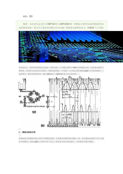
编辑:DD摘要:还在因为无法区分KBPC810与KBPC808哪一种整流方桥更加适用整流桥设计电路图而烦恼?强元芯小课堂帮您解决这些问题!整流桥电路图何处寻,ASEMI与子同袍。
很多情况下,我们的电路都是交流的,因此需要一个关键元器件---KBPC系列整流方桥,而直流电源的主要组成,就是把交流电在经过稳压、整流和滤波的一个过程。
今天就让我们跟随ASEMI半导体的脚步,一起来探讨,整流电路的特性,解决KBPC810与KBPC808难于区分的原因。
1:整流电路的分类电源电路中的整流电路主要有半波整流电路、全波整流电路和桥式整流三种,倍压整流电路用于其它交流信号的整流,例如ASEMI半导体中用于发光二极管电平指示器电路中,对音频信号进行整流。
2:常见三种整流电路的特性三种整流电路输出的单向脉动性直流电特性有所不同,半波整流电路输出的电压只有半周,所以这种单向脉动性直流电主要成分仍然是50Hz的,因为输入交流市电的频率是50Hz,半波整流电路去掉了交流电的半周,没有改变单向脉动性直流电中交流成分的频率;全波和桥式整流电路相同,用到了输入交流电压的正、负半周,使频率扩大在倍为100Hz。
3:常见三种整流电路的区分ASEMI半导体温馨提醒:在电源电路的三种整流电路中,只有全波整流电路要求电源变压器的次级线圈设有中心抽头,其他两种电路对电源变压器没有抽头要求。
另外,半波整流电路中只用一只二极管,全波整流电路中要用两只二极管,而桥式整流电路中则要用四只二极管。
根据上述两个特点,可以方便地分辨出三种整流电路的类型,但要注意以电源变压器有无抽头来分辨三种整流电路比较准确。
另外,ASEMI半导体提醒您注意一点:在整流电路中,输入交流电压的幅值远大于二极管导通的管压降,所以可将整流二极管的管压降忽略不计。
因此,一般来说KBPC810是比KBPC808更加适用于多样电路的。
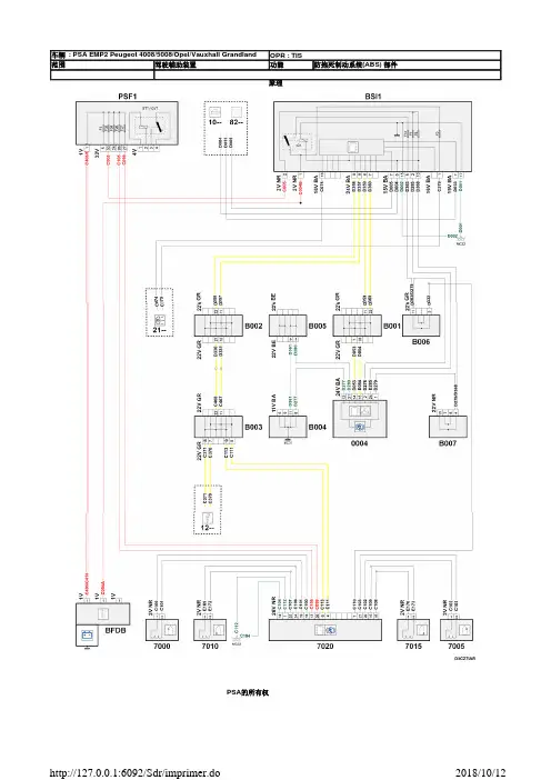
车辆 : PSA EM P2 Peugeot 4008/5008/O p e l /Va u xhall G r a n dla n d OPR : TI S范围 驾驶辅助装置 功能防抱死制动系统(ABS)部件原理PSA 的所有权项目代码说明信息0004null组合仪表(/)1320null发动机ECU /2120null制动双功能开关 /7000null左前防抱死制动系统传感器7005null右前防抱死制动系统传感器7010null左后防抱死制动系统传感器7015null右后防抱死制动系统传感器7020null防抱死制动控制单元B001null混合等电位接头 1B002null混合等电位接头 2B003null混合等电位接头 3B004null混合等电位接头 4B005null混合等电位接头 5B006null混合等电位接头 6B007null混合等电位接头 7BFDB null蓄电池插座处的保险丝盒BSI1null智能盒控制系统(BSI)CA00null点火开关 /E001null一个信息(或等电位001)压接导线MC32null车身接地点编号32MC33null车身接地点编号33PSF1null保险丝板-发动机室保险丝盒车辆 : PSA EM P2 Peugeot 4008/5008/O p e l /Va u xhall G r a n dla n d OPR : TI S范围 驾驶辅助装置 功能防抱死制动系统(ABS)部件线路PSA 的所有权项目代码说明信息0004null组合仪表(/)1320null发动机ECU /2120null制动双功能开关 /7000null左前防抱死制动系统传感器7005null右前防抱死制动系统传感器7010null左后防抱死制动系统传感器7015null右后防抱死制动系统传感器7020null防抱死制动控制单元B001null混合等电位接头 1B002null混合等电位接头 2B003null混合等电位接头 3B004null混合等电位接头 4B005null混合等电位接头 5B006null混合等电位接头 6B007null混合等电位接头 7BFDB null蓄电池插座处的保险丝盒BSI1null智能盒控制系统(BSI)CA00null点火开关 /E001null一个信息(或等电位001)压接导线MC32null车身接地点编号32MC33null车身接地点编号33PSF1null保险丝板-发动机室保险丝盒车辆 : PSA EM P2 Peugeot 4008/5008/O p e l /Va u xhall G r a n dla n d OPR : TI S 范围 驾驶辅助装置 功能稳定性控制部件原理PSA 的所有权项目代码说明信息0004null组合仪表(/)1320null发动机ECU /1630null自动变速箱 ECU /2120null制动双功能开关 /4400null驻车制动器开关6750null受控差速器控制单元7800null检查ECU稳定性7801null行驶稳定性调节关闭开关7803null转向角传感器,行车稳定性调节7804null转动 / 加速传感器 行车稳定性调节7810null左前稳定性控制传感器7815null右前稳定性控制传感器7820null左后稳定性控制传感器7825null右后稳定性控制传感器B001null混合等电位接头 1B002null混合等电位接头 2B003null混合等电位接头 3B004null混合等电位接头 4B005null混合等电位接头 5B006null混合等电位接头 6B007null混合等电位接头 7B008null混合等电位接头 8BFDB null蓄电池插座处的保险丝盒BSI1null智能盒控制系统(BSI)CA00null点火开关 /E001null一个信息(或等电位001)压接导线MC32null车身接地点编号32MC33null车身接地点编号33PSF1null保险丝板-发动机室保险丝盒车辆 : PSA EM P2 Peugeot 4008/5008/O p e l /Va u xhall G r a n dla n d OPR : TI S 范围 驾驶辅助装置 功能稳定性控制部件线路PSA Peugeot Citroen 的所有权项目代码说明信息0004null组合仪表(/)1320null发动机ECU /1630null自动变速箱 ECU /2120null制动双功能开关 /4400null驻车制动器开关6750null受控差速器控制单元7800null检查ECU稳定性7801null行驶稳定性调节关闭开关7803null转向角传感器,行车稳定性调节7804null转动 / 加速传感器 行车稳定性调节7810null左前稳定性控制传感器7815null右前稳定性控制传感器7820null左后稳定性控制传感器7825null右后稳定性控制传感器B001null混合等电位接头 1B002null混合等电位接头 2B003null混合等电位接头 3B004null混合等电位接头 4B005null混合等电位接头 5B006null混合等电位接头 6B007null混合等电位接头 7B008null混合等电位接头 8BFDB null蓄电池插座处的保险丝盒BSI1null智能盒控制系统(BSI)CA00null点火开关 /E001null一个信息(或等电位001)压接导线MC32null车身接地点编号32MC33null车身接地点编号33PSF1null保险丝板-发动机室保险丝盒。

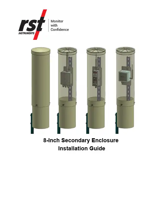
8-Inch Secondary Enclosure Installation GuideTable of Contents1P RODUCT O VERVIEW (3)1.1Dimensions (3)1.2Intended Audience (3)2R EQUIRED T OOLS (3)3I NSTALLATION G UIDES (3)3.1Install an 8-Inch Secondary Enclosure (3)3.2Install a DT2011B Data Logger (7)3.3Install a DT2055B Data Logger (9)3.4Install an Affinity Data Logger (10)4S ERVICE,R EPAIR AND C ONTACT I NFORMATION (12)R EVISION H ISTORY1 P RODUCT O VERVIEWRST’s 8-Inch Secondary Enclosure is built for use in remote locations wheredata loggers will require protection from natural elements and tampering fromvandals or wildlife. Designed for use with RST’s Affinity, DT2011B and DT2055Bdata loggers, this enclosure fully meets most site protection and securityrequirements.1.1 D IMENSIONSEnclosure only: Height 38.3" X Diameter 9.1"Enclosure with ground stake: Height 68" x Width 9.8"Enclosure with pole mounting bracket: Height 38.3" x Width 12.3"1.2 I NTENDED A UDIENCEThis guide is for the personnel installing an RST 8-inch secondary enclosure.This guide provides steps for installing a secondary enclosure and an Affinity,DT2011B or DT2055B data logger inside it.2 R EQUIRED T OOLSThe following tools you will need to install the secondary enclosure:•Screw driver•M6 hex driver•M10 wrench, ratchet socket wrench or adjustable wrench•Level (optional)•Hammer or mallet (to drive the ground stake)NOTE: Depending on the soil you are installing on, you may need an appropriatetool to drive the stake to the ground.3 I NSTALLATION G UIDES3.1 I NSTALL AN 8-I NCH S ECONDARY E NCLOSURETo install an 8-inch secondary enclosure, complete the following steps:1.Loosen the M6 hex head locking screw on the front of the enclosure.NOTE: Do not remove the M6 hex head locking screw from the lower enclosure.2. Twist the upper and lower sections of the enclosure and pull them apart.3. Unscrew the 36-inch ground stake from the lower enclosure.NOTE : Do not remove the mounting post. Do not discard the M10 hex head screws, washers, and nuts. You will need them to reinstall the ground stake.4.Drive the pointed end of the ground stake no more than 30” (762 mm) intothe ground. Make sure to leave 6” of the stake above the ground.NOTE: Depending on the soil you are installing on, you may need a hammer, a mallet, or an appropriate tool to drive the ground stake to the ground.5.Re-install the lower section of the enclosure to the ground stake using theM10 hex head screws, washers, and nuts.NOTE: Make sure the lower section of the enclosure is as close to the ground as possible without touch the ground surface.6.Install the data logger. Refer to the procedure specific to the data logger.•Install a DT2011B Data Logger•Install a DT2055B Data Logger•Install an Affinity Data Logger3.2 I NSTALL A DT2011B D ATA L OGGERTo install a DT2011B data logger to a secondary enclosure, complete thefollowing steps:1.Remove the front lid from the data logger.2.Find the mounting plate and the appropriate screws (check the label on thebag) for the data logger in the secondary enclosure package.3.Insert the screws through the mounting holes on the data logger.4.Screw the data logger onto the mounting plate with the antenna pointing up.5.Screw the front lid back onto the data logger.6.Slide the mounting plate downward on the mounting post to lock in place.head locking screw.NOTE: The see-through picture on the right is for illustration purposes only.3.3 I NSTALL A DT2055B D ATA L OGGERTo install a DT2055B data logger to a secondary enclosure, complete thefollowing steps:1.Remove the front lid from the data logger.2.Find the mounting plate and the appropriate screws (check the label on thebag) for the data logger in the secondary enclosure package.3.Insert the screws through the mounting holes on the data logger.4.Screw the data logger onto the mounting plate with the antenna pointing up.5.Screw the front lid back onto the data logger.6.Slide the mounting plate downward on the mounting post to lock in place.7.Twist the upper enclosure onto the lower enclosure. Tighten the M6 hexhead locking screw.NOTE: The see-through picture on the right is for illustration purposes only.3.4 I NSTALL AN A FFINITY D ATA L OGGERTo install an Affinity data logger to a secondary enclosure, complete thefollowing steps:1.Find the mounting plate and the appropriate screws (check the label on thebag) for the data logger in the secondary enclosure package.2.Insert the mounting screws through the back of the mounting plate.3.Screw the mounting plate onto the data logger with the antenna pointing up.4.Slide the mounting plate downward on the mounting post to lock in place.head locking screw.4 S ERVICE,R EPAIR AND C ONTACT I NFORMATIONContact RST for product services or repairs.•For sales information: ************************•For technical support: **************************•Website: •Toll free: 1-800-665-5599RST Canada Office (Head Quarters)Address: 11545 Kingston Street, Maple Ridge, BC, Canada V2X 0Z5Telephone: 604-540-1100Fax: 604-540-1005Business hours: 7:30 a.m. to 5:00 p.m. (PST) Monday to Friday, except holidaysRST UK OfficeAddress: Unit 4 Charles Industrial Estate Stowupland Road, StowmarketSuffolk, UK, IP14 5AHTelephone: +44 1449 706680Business hours: 9:00 a.m. to 6:30 p.m. (GMT) Monday to Friday except holidays。
JK V8 HEMI® BUILDER KITOverviewInstallation Guide5.7L &6.1L HEMI2007 - 2008 JK - SWB, LWBCongratulations on purchasing your AEV HEMI JK Installation kit. These instructions have been written for shops or DIY individuals with experience in general mechanics and welding. AEV also assumes that this kit will be installed in a shop environment with access to general shop equipment. If you are not familiar with JK systems, please reference the Jeep Service Manual available at any Chrysler dealer.TIP 1:Although it is not required, AEV recommends using a two post hoist to remove the body from the vehicle. The Jeep JK Wrangler was designed by Chrysler to have the body and chassis built as two complete assemblies which are then mated together on the assembly line, because of this; removal of the body only requires about 45 minutes. The general procedure is outlined below:1. Discharge the AC system2. Disconnect the steering linkage3. Disconnect the appropriate brake lines at the ABS Module4. Disconnect the battery harness from the battery.5. Disconnect the engine ground located to the left of the battery.6. Unplug the 34 way powertrain connector at the fire wall (C100) and the 34 way Chassisconnector (C300) on the right hand side of the radiator.7. Unplug the PCM (C1, C2, C3, and C4).8. Disconnect the front left O2 sensor located below the master cylinder.9. Drain and disconnect the radiator and heater hoses.10. Disconnect the transmission cooler lines at the radiator.11. Remove the power steering reservoir from the body.12. Remove all the body mounts.13. Disconnect the emergency brake cables at the rear axle.14. Disconnect the transmission and transfer case cables15. Disconnect the fuel fill hose.16. Disconnect all vapor lines at the purge valve.17. Disconnect the top of the rear axle vent line.Once the body is separated, it is easy to remove the stock powertrain, weld in the new mounts and to install the assembled 5.7 or 6.1L powertrain and exhaust into the chassis. While the body is on the hoist, the completed cooling module, battery tray, air filter, and steering modifications can be completed. The body is then mated back to the chassis using the reverse procedure, the harnesses are plugged in, the brake lines are hooked back up and bled, the radiator hoses can then be connected and the vehicle can be filled with fluid and started.TIP 2:There are several variations of sensors, alternators, power steering pumps and air conditioning compressors used in different applications from 2005 onward. Please check that you have all the correct parts listed in the Bill of Materials provided. Pay particular attention to the AC pump, power steering pump and cam sensor.TIP 3:The exhaust system is designed to fit the 5.7L motor in a stock application. 6.1L motors can use the 5.7 exhaust but will be required to use the 5.7L Manifolds, Gaskets, and bolts also listed in the Bill of Materials. The routing has been fitted assuming a stock suspension and bumpers. The use of aftermarket suspensions, bumpers or other components may require modifications to the exhaust system or other components. Two Door Wranglers will need a section of straight exhaust pipe cut out of the system.TIP 4:Jeep Wranglers being converted from Manual to Automatic Transmissions will require AEV Part #31001027AA which is an additional wire for the body side of the harness. The other parts required to perform the manual to automatic conversion are listed in the Bill of Materials.TIP 5:Four door wranglers can use the stock driveshaft’s front and rear; two door models will need a new or modified rear driveshaft.TIP 6:WK and XK powertrains come with a rear sump aluminum oil pan. This pan will work but is easily damaged off-road. As an option, a steel pan is available from the Dodge Ram and all parts are listed in the supplied Bill of Materials. LX powertrains come with a front sump aluminum pan and will need to be changed to the steel pan. Be sure to reference a 5.7 manual regarding the “Torque To Yield” main bearing cap bolt.TIP 7:The stock JK transfer case cable bracket must have the corner clipped off in order to clear the floorpan as shown in the photo.FIG. 1The AEV Harness is the same for 5.7L and 6.1L conversions. There are two connectors included that are for the 5.7L engines only and must be tied up on 6.1L conversions. The MDS connector located at the top rear of block must be zip tied to the harness and will not be used for 6.1L. The EGR solenoid connector (black 6-way) located at the front right of engine has a plastic clip located in the connector which is designed to fasten under the air filter bracket on 6.1L conversions.TIP 8:5.7 conversions can utilize the Grand Cherokee or Commander engine cover however it must be modified prior to installation using the template provided on the last page of this document (FIG. 2).COMMENTS OR QUESTIONS? American Expedition VehiclesPhone: 406.251.2100Email:************************ Website: Remove thisJK V8 HEMI® BUILDER KITEngine & Transmission MountingInstallation Guide5.7,6.1 WK or XK Powertrains with Dodge 4WD Adapter in place07+ JK – SWB, LWB, LHD onlyINSTRUCTIONSA. MOUNTING PREPARATION1. After the 3.8L Powertrain is removed, disconnect the front ABS connectors at the frameand remove the right side wiring harness bolt on clips that are located on the framebehind the right side shock tower.2. Cut off the OE engine mounts from the frame and clean up the area with an 80 gritsanding disc.B. INSTALLATION OF THE ENGINE MOUNTS1. Each engine mount has an L or R inscribed into the metal indicating the Left from theRight. There is also an arrow indicating the front of the mount.2. If the mounts are coated, remove the coating in all areas to be welded.3. Place the mounts on the frame rail and line up the oval holes precisely. Tack in placeand finish weld as shown.4. Paint all bare areas as required5. Reinstall the wiring harness mount with the stock hardware.C. INSTALLATION OF THE TRANSMISSION MOUNT1. All 5-45 Transmissions must have the ¾ Ton or 1 Ton Dodge 4WD adapter (Mopar52119433AB) along with the seal (Mopar 52119498AA) installed prior to the transmission mount.2. Install the AEV Mount to the 4WD Adapter on the transmission using the stock bolts.3. Install the stock JK transmission Isolator to the AEV Transmission Mount using the two3/8x1” bolts, nuts and washers and two 1/2”x1” bolts, nuts and washers.D. INSTALLATION OF THE CROSS-MEMBER MOUNT1. Begin by bolting the top plate of the transmission cross member mount to the JKtransmission isolator using the stock hardware.2. Bolt the top plate of the transmission cross member mount to the JK cross member using4 of the 1/2-13 bolts, washers and flange nuts.3. Bolt the bottom plate of the transmission cross member mount to the bottom of the JKcross member using three of the stock bolts into the cross member nutserts. Drill out one hole using the bottom plate as a drill template. Use the remaining two 1/2-13 bolts,washers and flange nuts to secure the bottom plate to the cross member.4. Remove any paint from the top and bottom plates and weld as shown.5. Paint any raw material and welds.COMMENTS OR QUESTIONS? American Expedition VehiclesPhone: 406.251.2100Email:************************ Website: JK OPTIMA GROUP 31 Battery TrayInstallation Guide3.8, 5.7, 6.1 Powertrains07+ JK - SWB, LWB, LHD only Stock battery or Optima Group 31PREPARATIONA. REMOVE THE FACTORY BATTERY TRAY1. Remove the factory Air box, Purge Valve, and Battery.2. Release the TIPM (fuse block) from the battery tray; disconnect the large 34 way (black)connector as shown.3. Remove the tray from the vehicle.B. INSTALL THE NEW TRAY1. The new tray is a tight fit and there is only one way to install it without bending themounting tabs. Place the new tray starting with the three bolts on the rear of the tray; try to slide the tray into place in the front of the vehicle using a motion that is horizontal, from the center of the vehicle outward. Use the factory bolts to fasten the tray into position.2. Remove the TIPM bracket and the speed nuts from the original tray, re-use this hardwareon the AEV Tray and re-mount the TIPM and 34 way connector.3. Trim the studs on the firewall using a cut-off wheel.4. Install the battery as shown using the included bracket, J-bolt and nut.5. Mount the purge valve and rearrange the hoses as shown.C. 3.8L AIR BOX MOUNTING1. Mount the included brackets as shown to the front of the AEV Battery Tray. Install thebolts from inside the battery tray outward.2. Remove the stock rubber air box isolators from the original tray and reuse them in thesupplied brackets.3. Mount the stock air box.D. 5.7L & 6.1L AIR FILTER BRACKET1. Using the filter bracket supplied with the HEMI kit, mount the bracket to the front of thebattery tray and to the front of the vehicle as shown. Install the bolts from inside the battery tray outward.2. Mount the supplied K&N air filter to the bracket. (K&N #RC-4630)COMMENTS OR QUESTIONS? American Expedition VehiclesPhone: 406.251.2100Email:************************ Website: JK V8 HEMI® BUILDER KITPlumbingInstallation Guide5.7L,6.1L WK or XK Powertrains w/AC Pump (55111414AA)and Power Steering Pump (5290778AA)07+ JK – SWB or LWB, LHD onlyA. AEV HEMI FUEL LINE1. Remove the locking clip out of the plastic fuel line at the tank as shown.2. Install the stud provided into the 5-45 transmission and reuse the steel fuel line bracketfrom the 3.8L engine.3. Install the AEV Fuel Line; be sure to lubricate all tubes or hoses prior to installation inorder to avoid damaging seals.B. POWER STEERING LINES1. This step is to be performed after the powertrain has been installed.2. Be sure you are using the correct power steering pump (Mopar #5290778AA)3. Install the lines as shown.4. Be sure to lubricate all O-rings prior to assembly.C. AEV AC LINES (BODY SIDE)1. Install the liquid line (Condenser to Firewall). Use the stock hardware to connect thelines.2. Fasten the line to the ground stud located on the left fender structure immediately behindthe ABS module using the supplied clip.3. Be sure to lubricate all O-rings prior to assembly.D. AEV AC LINES (POWERTRAIN SIDE)1. Be sure the correct AC compressor is being used (Mopar #55111414AA)2. Install the suction line (Compressor to Firewall) onto the compressor using stockhardware. The firewall side will be installed when the body is mated to the chassis.3. Install the AC Discharge line (Compressor to Condenser) to the compressor using thestock hardware. Install the stock pressure transducer. The condenser side will beinstalled when the body is mated to the chassis.4. Be sure to lubricate all O-rings prior to assembly.E. AEV TRANSMISSION COOLER1. Install the transmission cooler to the AC condenser as shown. Locate the cooler 3.5”from the top of the condenser and 3.5” from the right side of the condenser. Pre-install transmission cooler hose on each barb of the transmission cooler.2. Using the Mopar 55038175AA Transmission Cooler lines remove the OE hose portion asshown. Connect the Transmission Cooler lines to the transmission Cooler once the body is mated to the chassis.F. HEATER HOSES1. Cut the stock 3.8L hoses as shown and fit to the completed powertrain before mating thebody to the chassis.G. EVAPORATIVE PURGE VALVE HOSES1. Reuse the stock 3.8L hose from the fuel tank to the purge valve. Attach this line to thefuel line using the stock bracket and a couple zip ties.2. Use Mopar part #4578627AA hose to go from the intake, around the engine to the purgevalve. This hose doesn’t quite go all the way to the purge valve; you will need to use a portion of the stock 3.8L purge valve line from the purge valve to the engine.H. RADIATOR HOSES1. Install the upper and lower radiator hoses as shown.2. Trim the corner off of the fan shroud in order to clear the lower radiator hose.COMMENTS OR QUESTIONS? American Expedition VehiclesPhone: 406.251.2100Email:************************ Website: JK V8 HEMI® BUILDER KITExhaustInstallation Guide5.7L,6.1L WK or XK Powertrains w/Grand Cherokee or Commander Manifolds07+ JK - SWB, LWBAEV’s HEMI exhaust is designed specifically for the 5.7L HEMI but can be used on the 6.1L engine if the 5.7L manifolds, gaskets and bolts are used. The exhaust is designed around the stock suspension and bumpers and may need to be modified to accommodate aftermarket suspensions, bumpers or other accessories.DO NOT TIGHTEN ANY PART OF THE EXHAUST SYSTEM UNTIL THE FINAL DESIRED FIT IS ACHIEVED!1. Install the tailpipe section and isolator.2. Install the muffler section.3. Install the downpipes and catalytic converters.4. Install the hanger mount into the existing cross member hole behind the muffler.5. Adjust for clearances paying particular attention to the area around the front driveshaft,JK cross member, transmission pan, rear track bar and rear bumper. Once everything is adjusted properly, the clamps can all be tightened.6. The right hand down tube that goes under the transmission oil pan should be parallel withthe JK cross member when fitted properly.7. You may wish to tack weld all joints for increased durability.8. Install the star washers on the three isolator hangers.Note: 2DR Shown, 4DR SimilarNote: 2DR Shown, 4DR SimilarCOMMENTS OR QUESTIONS? American Expedition VehiclesPhone: 406.251.2100Email:************************ Website: 。
序言感謝您使用本產品,此份安裝手冊提供ASDA-AB系列伺服驅動器及ECMA系列伺服馬達的相關資訊。
在使用之前,請您仔細詳讀本安裝手冊以確保使用上的正確。
此外,請妥善將其放置在明顯的地點以便隨時查閱。
下列事項在您尚未讀完本安裝手冊前,請務必遵守:安裝的環境必須沒有水氣,腐蝕性氣體及可燃性氣體。
接線時禁止將三相電源接至馬達U、V、W的接頭,一旦接錯時將損壞伺服驅動器。
接地工程必須確實實施,接地時須遵照國家現行相關電工法規之規定施行(請參考NFPA 70: National Electrical Code, 2005 Ed.)。
在通電時,請勿拆解驅動器、馬達或更改配線。
在通電運作前,請確定緊急停機裝置是否隨時啟動。
在通電運作時,請勿接觸散熱片,以免燙傷。
更多ASDA-AB系列伺服驅動器及ECMA系列伺服馬達的相關資訊詳述於使用操作手冊內,您可至台達網站(/industrialautomation/)下載使用操作手冊(pdf檔)。
如果您在使用上仍有問題,請洽詢經銷商或者本公司客服中心。
由於產品精益求精,當內容規格有所修正時,請洽詢代理商或至台達網站(/industrialautomation/)下載最新版本。
安全注意事項ASDA-AB系列為一開放型(open type)伺服驅動器,操作時須安裝於遮敝式的控制箱內。
本驅動器利用精密的回授控制及結合高速運算能力的數位信號處理器(Digital Signal Processor,DSP),控制IGBT產生精確之電流輸出,用來驅動三相永磁式同步交流伺服馬達(PMSM)達到精準定位。
ASDA-AB系列可使用於工業應用場合上,且建議安裝於使用手冊中之配線(電)箱環境(驅動器、線材及馬達都必須安裝於符合UL50 Type 1或者是NEMA 250 Type 1的安裝環境最低要求規格)。
接收檢驗、安裝、配線、操作、維護及檢查時,應隨時注意以下安全注意事項。
接收檢驗安裝注意配線注意繁中-1操作注意¾當馬達運轉時,禁止接觸任何旋轉中的馬達零件,否則可能會造成人員受傷。
MK8 EGA EVO MM82004/E Setup GuideMK8烟气分析仪EVO MM82004/E 燃烧控制管理系统2022.04.29AUTOFLAME ENGINEERING LTD AUTOFLMAE 工程有限公司Unit 1-2, Concorde Business Centre Airport Industrial Estate Wireless Road, Biggin Hill Kent TN16 3YN United Kingdom燃 烧 控 制 管 理 系 统+44 (0)1959 578 820 Tel:******************************Email: Website:Technical Manual技术手册Mk8 EGA EVO Setup Guide Mk8 烟气分析仪EVO 安装指南Part No. MM82004/E2022.04.29This manual and all the information contained herein is copyright of Autoflame Engineering Ltd. It may not be copied in the whole or part without the consent of the Managing Director.Autoflame工程有限公司拥有本手册的所有版权。
在未经Autoflame公司常务董事同意的情况下,本手册内容不得被整体或部分引用。
Autoflame Engineering Ltd’s policy is one of continuous improvement in both design and manufacture. We therefore reserve the right to amend specifications and/or data without prior notice. All details contained in this manual are correct at the time of going to print.Autoflame工程有限公司致力于不断提升Autoflame产品的设计和制造,我们保留修订本手册规范/数据的权利,恕不另行通知。
编辑人:MM
摘要:整流桥KBL608扁桥,它的电性参数为6A800V;台湾ASEMI品牌采用88MIL大芯片,浪涌电流Ifsm可以达到150A;
整流桥KBL608扁桥,它的电性参数为6A800V;台湾ASEMI品牌采用88MIL大芯片,浪涌电流Ifsm可以达到150A;ASEMI主营的就是整流桥、肖特基二极管、快恢复二极管!强元芯12年专注整流桥生产可不是说说而已,有许多经销商、采购经理都来找ASEMI官网,来寻得他们想要的集成整流桥型号全系列资料。
本文主要详解KBL608扁桥!
KBL608参数工艺
漏电流(Ir):5uA;工作温度:-55℃~150℃;恢复时间(Trr):500ns;采用激光打标印字,镭射激光打标,永不褪色,解决油墨丝印易掉色问题,激光打标生产效率高,订货货期短,同时也解决油墨印字货期长、低效率问题,预留定位孔方便安装散热装置;采用台湾波峰GPP
芯片,而该芯片具有良好的稳定性及抗冲击能力,保证了最大整流电流稳定,最大反向耐压稳定。
KBL608应用领域
KBL608主要应用于小电流领域产品:小功率开关电源,电源适配器,LED灯整流器,手机充电器,家用小电器等相关电器产品!好产品是不会被人所嫌弃的。
强元芯电子也一直致力于打造出最节能,稳定,适合开关电源的整流桥堆KBP608来为大众服务,产品性能让客户更加有所放心。
强元芯12年生产经验,专业的自动化设备支持注塑一步成型,12年品质如一日,选择强元芯,让您更放心。
辑人:MM
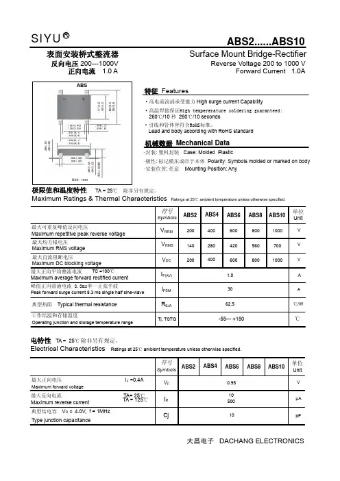
ABS8,整流桥ABS8,ASEMI品牌迷你整流桥,为你带来而目一新的整流产品摘要:ABS8,整流桥ABS8,ASEMI品牌迷你整流桥,为你带来而目一新的整流产品,本文将为大家讲解一款迷你整流桥
ABS8,是ASEMI品牌迷你整流桥当中ABS封装系列当中的一个常规型号,它最常用的领域就是LED灯和手机充电器当中,在其中作前端整流输入的用途,众所周知,除了某些个别的电器之外,绝大多数我们生活中要使用的电器都需要用直流电才能正常工作,整流桥是把交流电转变成直流电最重要最关键的元件,那么下面我们就来一起认识一下这一款产品吧
ABS8当中的数字要如何解释呢?这就要讲到一款整流桥的电性参数。
整流桥ABS8,它的电性参数是:正向电流(Io)为1A,反向耐压为800V,正向电压(VF)为1.0V,它的浪涌电流Ifsm为35A,漏电流(Ir)为5uA、工作温度在-40°~+150℃,恢复时间(Trr)达到500ns,其中有4条引线。
对照看下来,我们就能够找出规律,在ABS8这款整流桥中“8”这个数字就代表着最大反向耐压的数值。
同理可知,封装相近的型号比如ABS10,它的参数就是1A,1000V,那么这个系列的参数你知道了吗?
最后我们再来一起看一下整流桥ABS8尺寸参数介绍,了解封装外观具体规格是怎样的。
ABS8采用GPP芯片材质,里面有4颗芯片组成,芯片尺寸都是50MIL。
整流桥ABS8采用激光打标,印字非常清晰,永不褪色,防止假冒。
具体尺寸参数详解如下图所示:
ABS8贴片整流桥详解ASEMI品牌原装进口
ASEMI整流桥ABS8,采用SOP-4贴片封装,使用台湾进口波峰GPP大芯片制作,50MIL大芯片,电流可以达到1A,电压为800V,制造的整流桥一般体现在抗电流电压浪涌冲击,离散性,参数一致性,能耗差异等等方面。
具有耐高抗浪涌冲击的优势,开机瞬
间百倍电流电压依然稳定工作,不发热不炸机。
ASEMI品牌整流桥质量稳定,性价比高,被誉为整流行业品牌,品质源于核“芯”。
ASEMI12年大品牌,中国整流桥堆知名企业
ASEMI-中国整流桥堆知名企业,12年来专注电源领域,有着先进的台湾技术设备健鼎一体化测试设备和最好的整流桥研发生
产经验,170人的专业研发整流桥堆团队为您打造核“芯”产品。
为了从源头上保证ABS8等整流桥堆的持续稳定,主要功劳便属内部核心采用的台湾进口GPP芯片,该芯片具有良好的稳定性及高抗性能。
ABS8是一款由外籍工程师和ASEMI团队精心研发打造的一款高性能整流桥堆,常用于LED灯上。
ASEMI品牌在质量上显得更加沉稳,在工作时应对自如,这主要源于它的内部核心上的优势。