哈里伯顿固井工艺及固井新工具
- 格式:pdf
- 大小:3.34 MB
- 文档页数:17
俄罗斯固井质量测井仪器与哈里伯顿INSITE系列测井系统的挂接【摘要】本文介绍了俄罗斯固井质量测井仪器的基本特性及功能,重点是解决了实际生产中不同测井系统挂接的需求。
针对俄罗斯固井质量测井仪器与insite系列测井系统挂接之间存在的问题,包括gector地面采集系统的挂接;gector地面采集系统深度信号的获取;地面系统的供电组成;井下仪器3芯接头与insite系列19芯接头的转换问题等,提出了合理有效的解决方案,实现了两套不同系统之间的挂接,充分利用测井资源,提高了测井生产时效。
【关键词】声波变密度水泥胶结质量仪器挂接地面采集俄罗斯固井质量测井仪器即俄罗斯mak2—sgdt测井系统,采用声波变密度(mak2)和伽玛密度(sgdt)测井仪器相结合的组合形式定量的评价水泥胶结质量。
这套系统主要包括声波变密度测井仪、伽玛密度测井仪、gector地面采集箱、mak电源箱。
insite系列测井系统是美国哈里伯顿公司在excell2000系列测井系统基础上研制的新一代测井系统。
俄罗斯固井质量测井仪器和insite系列测井系统在测井中具有很大差异,测井系统整体结构大相径庭。
而俄罗斯固井质量测井仪器可以与insite测井系列在测井过程中的功能互补,通过两套系统的挂接,使两套系统在实际测井操作中协调工作,共同发挥它们的作用。
1 俄罗斯固井质量测井仪原理俄罗斯固井质量测井仪器采用声波变密度(mak2)和伽玛密度(sgdt)仪器相结合的形式评价水泥胶结情况。
mak2不提取首波绝对幅度的大小,而是研究首波的幅度衰减和时间特性;它测量首波到达接收器的时间、接收器记录的首波衰减、首波时差及首波衰减系数。
因此,mak2声波变密度仪器是通过测量首波衰减情况来评价第一、第二界面胶结质量。
sgdt伽玛密度仪器是通过放射源来反映水泥环的密度情况。
经过计算机处理,能够得到套管壁厚曲线、偏心率曲线、水泥平均密度曲线等。
通过这两种仪器测量的成果曲线信息,结合常规资料和地层密度等资料进行综合解释,综合评价水泥胶结质量、确定水泥返高和自由套管井段、检查套管损坏位置、检查套管程序以及确定套管相对与井壁的偏心率等。


固井历史上的重要事件:1903:F·F·希尔将50袋水泥混合后的纯水泥浆倒入井内,用于封堵井底水层。
1919:哈力伯顿——在北德克萨斯成立注水泥事务所。
1920: 哈力伯顿——发明了射流水泥混合器。
1921:J·T·白奇曼、散塔克鲁兹水泥石油公司——发明了初期水泥试验技术。
1922:哈力伯顿——提出了双塞注水泥浆法专利技术。
1927:独星水泥公司——在印第安纳首次制造了高细度抗硫酸盐水泥。
1929:哈力伯顿——建立了第一个测定油井水泥性能的实验室。
1930:哈力伯顿、汉布莱石油与炼制公司、加利福尼亚标准石油公司——开始进行油井水泥研究工作。
1930:H·R·依尔文——取得了在套管外用扶正器方法的专利。
1930:搬土被引进到石油工业,用于钻井泥浆及水泥。
1932、1934:威拉姆兰诺与瓦尔特威尔斯——在加利福尼亚及墨西哥沿岸使用了射孔枪。
1934: B·C·克拉夫特等、加利福尼亚标准石油公司——提出了水泥稠化时间测定仪结构的报告。
1937:J·E·勒尔、哈力伯顿——制造了测定油井水泥性能的双容器装置。
1937:API——成立了油井水泥研究委员会。
1938:R·F·法里斯、斯塔诺林德油气公司——制造了第一台高温高压水泥浆稠化时间测定仪。
1939:汉布莱石油与炼制公司——在水泥内混入少量的卡诺特石(钒钾铀矿)以使用伽马测井法来确定套管外水泥返回顶部的位置。
1939:肯艾斯瑞特与布鲁斯巴斯特——在加利福尼亚第一次使用市售井壁刮泥器。
1940:M·M·肯莱——第一次用电缆进行井径测井,以确定所需水泥的量。
1952:API——批准了关于油井水泥实验的API规程32(第一版)。
1953:飞利浦斯石油公司——把降失水剂产品和硅藻土介绍到工业界。
1957:哈里伯顿——介绍了加重剂。
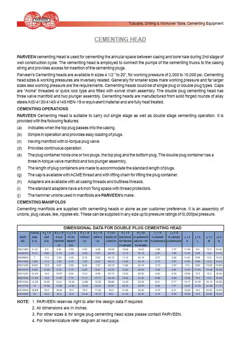
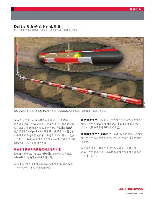
CEMENTING HEADPARVEEN cementing Head is used for cementing the annular space between casing and bore hale during 2nd stage of well construction cycle. The cementing head is employed to connect the pumps of the cementing trucks to the casing string and provides access for insertion of the cementing plugs.Parveen's Cementing heads are available in sizes 4 1/2 ” to 20”, for working pressure of 2,000 to 10,000 psi. Cementing head sizes & working pressures are inversely related. Generally for smaller sizes mare working pressure and far larger sizes less working pressure are the requirements. Cementing heads could be of single plug or double plug types. Caps are “Acme” threaded or quick lock type and fitted with swivel chain assembly. The double plug cementing head has three valve manifold and two plunger assembly. Cementing heads are manufactured from solid forged rounds of allay steels AISI 4130/4140/ 4145 HEN-19 or equivalent material and are fully heat treated.CEMENTING OPERATIONSPARVEEN Cementing Head is suitable to carry out single stage as well as double stage cementing operation. It is provided with the following features:(a) Indicates when the top plug passes into the casing.(b) Simple in operation and provides easy loading of plugs.(c) Having manifold with lo-torque plug valve.(d) Provides continuous operation.(e) The plug container holds one or two plugs, the top plug and the bottom plug. The double plug container has athree in-torque valve manifold and two plunger assembly.(f) The length of plug containers are made to accommodate the standard length of plugs.(g) The cap is available with ACME thread and with lifting chain for lifting the plug container.(h) Adapters are available with all casing threads and buttress threads.(i) The standard adapters have a 6 inch Tong space with thread protectors.(j) The hammer unions used in manifolds are PARVEEN's make.CEMENTING MANIFOLDSCementing manifolds are supplied with cementing heads or alone as per customer preference. It is an assembly of unions, plug values, tee, nipples etc. These can be supplied in any size up to pressure ratings of I0,000psi pressure.NOTE: 1. PARVEEN reserves right to alter the design data if required.2. All dimensions are in inches.3. For other sizes & for single plug cementing head sizes please contact PARVEEN.4. For Nomemclature refer diagram at next page.CEMENTING HEAD CFO™Multiple-Stage Cementing Systemmultiple-stageFO cementer)is used to placestages of cement or othera casing string at differentalong the casing.This tool isand requiresthe use of astring and the sleevetools.These operatingthrough Halliburton toolas rental items.In addition,manufactured for customerare made of heat-treatedhardness of RC 21.are suitable for use with H-40,and N-80grades of casing.be used in sour servicegas –H 2S and sour oil)The Halliburton series of FO(full-opening)cementing tools consistsof the following equipment:•FO multiple-stage cementers•Opening and closing sleeve positioners•Standard isolation packers•Port valve isolation packers•RTTS™circulating valves•FO inflatable packer collarsFeaturesThe FO cementer has the following unique advantages:•Any number of tools can be run in the same string.•No plugs or seats must be drilled out at the cementer.•Operators can open or close the tool whenever necessary.•The tool can be used to test,treat,and evaluate a zone in the wellbefore it is reclosed.CEMENTINGHALLIBURTONFO stage cementer shown in a typical off-bottom cementing application where Delta Stim®sleeve collars,Swellpacker®isolation system and annular casing packers are all run in a single string.Sales of Halliburton products and services will be in accord solely with the terms and conditions contained in the contract between Halliburton and the customer that is applicable to the sale.H067683/09©2009HalliburtonAll Rights ReservedPrinted in U.S.A.HALLIBURTON FO sleeve with port isolation packer30/06/2000Slim-line Re-lining is a technique designed to fit a well liner with the minimum reduction of well diameter. It is based on using a Swage Packer to seal the base of the liner into the old casing or a screen. Briefly, a Swage Packer is a thin wall pipe with a vulcanized rubber cover that can be expanded radially using a high-pressure inflatable packer to create a well seal. The attached drawings P663A and P663B show the two most common methods of applying this technique.The first of these shows re-lining using a swaged packer and cementing the annulus between the liner and the existing casing. The basic installation steps, as indicated on the drawing are: • Clean the existing casing and inspect to ensure it’s ready to receive the liner. In some cases, this may require a deviation survey in addition to video inspection.• Attach the Swage Packer and one-way grouting valve assembly to the 1st joint of the liner. The drawing shows this as a welded connection but threaded or even glued and pinned connections are also possible.• Run the liner in to the required depth. Note that, if the liner is to tie back to the surface, the liner can be run as usual, however, it is also possible for the liner top is to terminate below surfacewhich is described below.• Make-up the High Pressure Swaging Packer, straddle pipe and low pressure cementing packer.• Run this assembly inside the new liner to locate the HP Swaging Packer adjacent to the Sage Packer. The two different packers each have separate inflation hoses to allow independentoperation.• Inflate the HP packer to sufficient pressure to deform the Swage Packer out into firm, sealing contact with the existing casing. This operation is controlled in terms of both inflation pressure and volume against pre-tested standards for each.• With the HP packer still inflated, inflate the LP cementing packer to isolate the one-way cementing valve.• Hook up a pumping head to the drill rods and establish circulation to the liner/casing annulus with water then switch over to cement grout and pump grout to fill the annulus.• Deflate the LP cementing packer and flush the excess grout out of the rods and straddle zone.Obviously, to minimize flushing, a water tail can be pumped following the cement and thestraddle pipe can also be set-up to accept a wiper plug if required.• To complete the re-lining simply deflate the HP packer and trip out of the hole.The liner can be manufactured from any compatible material, e.g. standard steel casing, PVC, ABS, FRP, etc. Since the liner is not deformed in any way and the Swage Packer will be expanded to a larger ID than the liner, it’s the liner itself which determines the minimum finished ID of the lined well. Selection of the liner will depend on factors such as minimum running and grouting clearance, method of joining, well fluid conditions, minimum allowable ID and, inevitably, availability.If using a thin wall or other low collapse strength liner, a third inflatable packer (or other closure method) may be run at the surface and the annulus between the drill rods and the liner can be water filled and slightly pressurized to prevent collapse during cementing. In this case it essential to pump a water tail after the grout, preferably with a wiper plug, as the liner must remain pressurized until the grout has reached initial set at least.The 2nd re-lining technique shown involves deforming both the Swage Packer and the liner. In this case, they are both usually manufactured from the same size pipe – either stainless steel or carbon steel as appropriate to the installation. The installation procedure is similar to that given above except for the steps involved in cementing the annulus. In their place, after performing the initial setting of the Swage Packer, the HP packer is deflated, moved up hole and re-inflated to swage out the liner. This process continues in a stepwise fashion until the complete liner has been swaged out.Normally, it is the swaged ID of the Swage Packer which represents the minimum ID of the lined well in this case. Typically, for water wells, this will be around ½” (13 mm) less than the existing casing ID and thus represents a minimal reduction of diameter.As mentioned above, it is possible to locate the liner top some depth below surface. In this case, following make-up of the liner to the length required, the liner is hung off and the packer assembly is run into the liner on drill pipe. Locating the HP packer adjacent to the Swage Packer, as previously, this packer is inflated to a pressure sufficient to provide a high strength anchor on the inside of the liner but less than that required to begin setting the Swage Packer. The liner is then lowered to its required depth using the drill pipe and the frictional anchor provided by the inflate HP packer. On depth, the pressure in the HP packer is simply increase to set the Swage Packer.Apart from the obvious advantages of these techniques to produce very slim-line re-lines, it may be noted that at no time is a conventional drill rig required. All operations may thus be performed using a crane and simple casing & rod slips thus reducing costs and scheduling constraints. Furthermore, there is no need to kill a producing well, even an artesian well, in order to reline using these techniques as the inflatable packers may be used, in conjunction with appropriate surface equipment, to prevent contamination of the aquifer with cement or uncontrolled flow situations.The Slim-line Re-lining techniques described were first introduced by AGE Developments Pty Ltd (AGE) of Perth, Western Australia in 1993 and are offered internationally by Inflatable Packers International (IPI).By Clem Rowe, Managing Director, Inflatable Packers International Pty Ltd © 30 June, 2000。
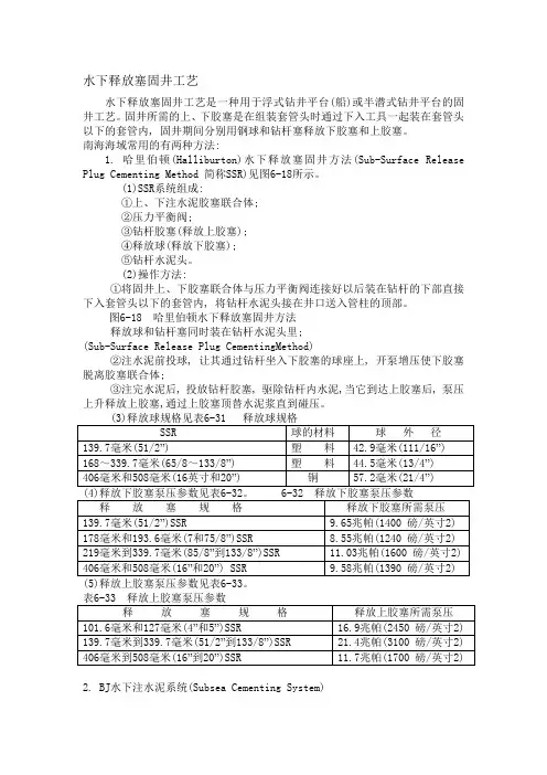
水下释放塞固井工艺水下释放塞固井工艺是一种用于浮式钻井平台(船)或半潜式钻井平台的固井工艺。
固井所需的上、下胶塞是在组装套管头时通过下入工具一起装在套管头以下的套管内, 固井期间分别用钢球和钻杆塞释放下胶塞和上胶塞。
南海海域常用的有两种方法:1. 哈里伯顿(Halliburton)水下释放塞固井方法(Sub-Surface Release Plug Cementing Method 简称SSR)见图6-18所示。
(1)SSR系统组成:①上、下注水泥胶塞联合体;②压力平衡阀;③钻杆胶塞(释放上胶塞);④释放球(释放下胶塞);⑤钻杆水泥头。
(2)操作方法:①将固井上、下胶塞联合体与压力平衡阀连接好以后装在钻杆的下部直接下入套管头以下的套管内, 将钻杆水泥头接在井口送入管柱的顶部。
图6-18 哈里伯顿水下释放塞固井方法释放球和钻杆塞同时装在钻杆水泥头里;(Sub-Surface Release Plug CementingMethod)②注水泥前投球, 让其通过钻杆坐入下胶塞的球座上, 开泵增压使下胶塞脱离胶塞联合体;③注完水泥后, 投放钻杆胶塞, 驱除钻杆内水泥,当它到达上胶塞后, 泵压上升释放上胶塞,通过上胶塞顶替水泥浆直到碰压。
2. BJ水下注水泥系统(Subsea Cementing System)(1) 系统组成(见图6-19):上、下胶塞联合体;(2)下入工具总成;③释放球;④钻杆胶塞;⑤钻杆水泥头。
(2) 操作方法:①将上、下胶塞联合体装在下入工具的下部;②将下入工具装在钻杆的底部, 并用钻杆送入套管头以下的套管内;③注水泥前投球, 让其通过钻杆坐入下胶塞的球座上, 开泵增压使下胶塞脱离胶塞联合体;④注完水泥后, 投放钻杆胶塞, 驱除钻杆内水泥, 当它到达上胶塞后, 提高泵压释放上胶塞,通过上胶塞顶替水泥浆直到碰压。
(5)释放上、下胶塞所需泵压见表6-34。


CementingHALLIBURTONHT -400™ PumpThe Industry StandardH alliburton’s HT-400™ Pump is a lightweight,rugged,versatile unit that was introduced in 1957.Its name denotes Horizontal Triplex and its original rating of 400 horsepower.Since its debut,the basic design has been improved and upgraded until it now is rated at 800 hp maximum in some configurations.The pump has performed millions of operating hours in fracturing,acidizing,cementing,and sand and water control work.FeaturesThe Halliburton twin-pump or flexibility concept is particularly useful when precise pumping ranges andcontrols are required.Halliburton exclusively manufactured the HT-400 pump power end,so that practically all parts are interchangeable.The exception is that the power end case is built in both left- and right-hand configurations.Internal parts,including the proven worm/ring gear sets,are identical,only the case is different.Power ends can be fitted with any of the five sizes of fluid ends – 3 3/8”,4”,4 ½”,5”and 6”plungers – each with characteristics suitable for specific applications.Power end components:•Case and Drive Gears:Power End cases aremanufactured exclusively by Halliburton in both left- and right-hand models.They are made of high-strength weldments of Halliburton design.They are not interchangeable.•Crankshaft:Heat-treated steel forgings are used to manufacture crankshafts.All cranks are the same,even for left- and right-hand units.•Connecting Rods:Connecting rods are made from aluminum forgings.The identical rods are internally drilled to provide lubrication to the crosshead pins.•Crossheads:Crosshead bodies are made of heat-treated steel alloy castings.They are fitted with replaceable,high-leaded bronze shoes on both top and bottom.•Lubrication:Standard self-contained power endlubrication system is pressurized by an internal crescent gear-type pump driven off the end of the worm gear.Positive pressure lubrication is supplied to the crosshead slides,gear support bearings,crankshaft throws and crosshead pins.•Cooling:Tube-and-shell coolers are optional add-on components,which provide remote cooling capacity.The HT-400 pump can be fitted with radiator-type,air-to-oil or water-to-oil cooling systems as well.Spacers are special components designed to separate the fluid end from the power end of the HT-400 pump.The interchangeable spacer insures that fluids being pumped do not contaminate the power end and cause premature failures.Each fluid end package is manufactured from three separate chambers – all identical and completely interchangeable.If one chamber of a fluid end should cause trouble,it can be changed quickly and the pump returned to duty.Fluid End components:•Chambers:The fluid end is constructed from threeseparate but identical forged and heat-treated chambers.Fluid ends can be supplied in any of five plunger sizes and each size can be fitted to the standard power end without alteration of either fluid or power end.•Valves and valve seats:Fluid ends are fitted withreplaceable,carburized valves and seats of Halliburton design and manufacture.Most of the valve assembly parts are interchangeable between suction and discharge ports within a given size and some are even interchangeable between sizes.•Lubrication:A separate lubrication system supplies lubricant to the fluid end package.H A L 17345Fluid end viewSales of Halliburton products and services will be in accord solely with the terms and conditions contained in the contract between Halliburton and the customer that is applicable to the sale.H04798 04/06© 2006 Halliburton All Rights ReservedPrinted in U.S.A.TestingEach HT-400 pump undergoes rigorous testing before it is placed in service.Fluid end chambers are tested individually to pressures far beyond the anticipated operating pressures and then tested again when they are assembled into three-chamber fluid ends.A third test is performed after the fluid end is attached to the power end assembly.Power ends are submitted to equally rigoroustesting in a Halliburton test facility.Pumps are run for over an hour at various speeds and at various pumping pressures before they are installed on a unit.After the unit is completed,each pump is further tested during the unit checkout.H A L 17346Mounted on a skid — close-upFluid end ring gear viewMounted on Advantage™ skid unit — side viewH A L 17347H A L 17348。