ds-k1f600-d6e说明书
- 格式:docx
- 大小:12.43 KB
- 文档页数:1
绪 言承蒙惠顾,购得 DS-2600打印机。
在使用本机前,请细阅这本用户手册,以便能正确使用。
并且请妥善保存这本手册,万一有不了解或故障时,这本手册会带给您很大的帮助。
DS-2600打印机是得实集团吸收日本的先进技术,自行开发和生产的通用80列多功能超高速24针汉字打印机。
DS-2600具有高速度打印、7联高穿透力打印、多功能易操作面板等硬件功能。
在软件方面,DS-2600具有图形全双向打印、表格线自动连接、超行宽自动压缩、自动撕纸、纸张设定。
通过参数设置,DS-2600可选择 ESC/P、LQ等仿真模式。
打印针调整和断针自动补偿功能是得实打印机的专利技术。
DS-2600的外型精巧美观、操作方便,特别适合邮政、税务、医院、银行等行业,打印单层/多联票据、凭证使用。
对不需要打印宽幅内容的企业用户,DS-2600也是物美价廉的好选择。
目录第1章安装打印机.....................................1-11-1 开箱和检查......................................1-1 1-2 放置打印机......................................1-2 1-3 打印机部件......................................1-3 1-4 安装............................................1-5第2章纸的安装和使用.................................2-12-1 选纸............................................2-1 2-2 调校打印头间隙..................................2-1 2-3 装入链式纸......................................2-2 2-4 装入单张纸......................................2-4第3章控制面板.......................................3-13-1 按钮及其指示灯..................................3-1 3-2 开机功能........................................3-4 3-3 组合功能........................................3-6第4章 参数设置.......................................4-14-1 如何选择打印机参数设置..........................4-1 4-2 如何进行参数设置................................4-2 4-3 如何进行纵向校正...............................4-15 4-4 如何进行打印针自动调整.........................4-17 4-5 如何进行打印针补偿设置.........................4-19 4-6 如何恢复出厂设置...............................4-21 4-7 如何进行撕纸位置调整...........................4-22 4-8 如何进行页首调整...............................4-22第5章故障及保养.....................................5-15-1 故障处理........................................5-1 5-2 保养与维护......................................5-7第6章参考...........................................6-16-1 打印机规格......................................6-16-2 接口............................................6-8 6-3 票据打印.......................................6-10 6-4 字符集.........................................6-11 6-5 控制码摘要表...................................6-17安全规范企业公开信息:1.售后服务请致电全国各地得实服务网点电话,或拨打:400-810-9998(手机)800-810-9998(免费)2.产品工作、待机、休眠及关闭状态的最大及最小能耗如下:产品使用状态最大能耗最小能耗工作时250W 10W待机10W 8W休眠7W 7W关闭小于0.1W 0注:只有当产品无任何外接输入电源时,才能实现零能耗。
6100系列视频服务器用户使用手册(Ver2.0)非常感谢您购买我公司的产品,如果您有什么疑问或需要请随时联系我们。
本手册适用于DS-6100HC、DS-6100HF视频服务器。
本手册可能包含技术上不准确的地方、或与产品功能及操作不相符的地方、或印刷错误。
本手册的内容将根据产品功能的增强而更新,并将定期改进或更新本手册中描述的产品或程序,更新的内容将会在本手册的新版本中加入,恕不另行通知。
物 品 清 单小心打开包装盒,检查包装盒里面应有以下配件:¾一台视频服务器¾一本用户手册¾一根DTE线¾一根电源线¾一张保修卡¾一张合格证¾一个光盘如果发现有所损坏或者任何配件短缺的情况,请及时和经销商联系。
第一章用户手册简介感谢您购买DS-6100系列视频服务器!在您准备使用本产品之前,请先仔细阅读本手册,以便能更好的使用本产品的所有功能。
1.1用途本手册的用途是帮助您熟悉和正确的使用DS-6100系列视频服务器!1.2用户手册概述第一章:用户手册简介第二章:产品概述第三章:硬件安装第四章:软件安装第五章:参数配置第六章:广域网接入附录A:常见问题解答附录B:技术参数第二章产品概述2.1产品简介DS-6100系列视频服务器是专为远程监控而设计的嵌入式数字监控产品,采用最新的达芬奇平台处理芯片,LINUX嵌入式系统,完全脱离PC 平台,系统调度效率高,代码固化在FLASH中,系统运行更加稳定可靠。
DS-6100系列视频服务器具有视频信号和音频信号的硬件同步压缩功能,压缩码流通过网络进行传输,通过网络可进行实时视频和音频预览,支持流协议(RTP/RTCP),支持IE预览,支持双向语音对讲,多种语言支持等功能。
2.2 产品型号说明根据编码分辨率分两种:¾DS-6100HC:1~4路视频,音频输入,每路的视频分辨率最高支持CIF,也可以选择QCIF,不可以安装硬盘。
XMT — 6000 系列仪表使用说明书目录一、概述(1)、主要特点(2)、型号定义二、技术规格三、面板说明及操作说明(1)、面板说明(2)、操作说明1、上电过程2、给定值/手动输出值设置3、启动自整定4、参数设置四、参数功能及设置(1)、参数速查表(2)、参数详细说明1、软件参数锁Loc2、与仪表输入有关的参数(SN、DIP、DIL、DIH、DL、SC)3、与仪表报警输出有关的参数(HIAL、LOAL、DHAL、DLAL、DF、ALP)4、与控制输出有关的参数(CF、OP1、OPL、OPH、CTRL、RUN)5、与自整定有关的PID控制参数(M50、P、T)6、与仪表通讯/变送输出有关的参数(CF、ADDR、BAUD、DIL、DIH)7、现场参数(EP1—EP8)五、仪表接线六、典型应用XMT—6000D系列仪表使用说明书目录一、概述(1)、功能简述(2)、型号定义二、面板说明及操作说明(1)、面板说明(2)、操作说明1、设置程序2、设置参数3、显示及修改程序运行段号4、显示运行时间5、运行时修改程序曲线6、运行/暂停(run/HoLd)7、停止(StoP)8、自整定(AT)三、概念解释四、程序编排与操作(1)、时间设置(2)、给定值设置(3)、程序的输入操作(4)、运行多条曲线时程序的编排方法(5)、外部事件输入接口五、停电处理六、与XMT—6000系列仪表的不同之处1、系统运行参数2、参数设置权限选择Loc3、输出定义参数oP14、功能参数CF5、现场定义参数(EP1—EP8)6、仪表与计算机通讯XMT—6000系列仪表使用说明书一、概述(一)主要特点:◆采用先进的微电脑芯片及技术,减小了体积,并提高了可靠性及抗干扰性能。
适用于各种温度,压力,流量,液位, 湿度等的测量控制。
◆按国际标准制造,具备85—265VAC宽范围输入的自由电源供选配,备有多种安装尺寸。
◆输入采用数字校正系统及自校准技术,测量精确稳定,消除了温漂及时漂引起的测量误差。
开关柜智能操控装置使用说明书开关柜智能操控装置使用说明书一.产品概述RT-KZ100系列开关柜智能操控装置是一种新型的集多功能开关模拟显示、温湿度数据显示、多参数监控于一体的高度集成化装置,可用于各种电压等级的开关柜,包括中置柜、手车柜、固定柜、环网柜等多种柜体。
具有动态一次模拟图、柜内温湿度显示、高压带电提示、自动除湿等功能,特别是其中应用了本公司自主知识产权的热故障预警系统技术——以无线传输的方式将柜内各触头、母排及电缆头的温度采集到主机上面,通过液晶屏显示出来,同时设置了温湿度和温升的超限报警等独特功能,为同行业类似产品所不及。
并且具有RS485通讯接口,可与上位机的组态软件实时通讯,使用户在值班室就能及时得到现场的开关柜状态和温湿度数据,以便统计和分析。
人体感应带电提示、语音防误提示、带电闭锁、自动加热除湿,大大增加了装置的安全性能。
此外还具有电力参数测量,包括电流、电压、有功功率、无功功率显示等功能,给用户提供足够的信息量。
集多种功能于一身,可取代现有的许多功能单一的测控装置。
精心的电路设计、工业级的电子元器件选用、严格的整机带电老化和出厂测试、及时周到的售后服务等措施确保产品的长期可靠性。
二.主要技术指标1.使用环境:温度-20~+85℃,相对湿度≤95%RH2.工作电压:AC220V/DC220V3.介质抗电强度:≥AC2000V4.绝缘性能:≥100MΩ5.抗电磁干扰性能:符合IEC255-22的标准规定6.温度测量范围:-20℃~+125℃,精度:±1℃7.湿度测量范围:0~100%RH,精度:±3.0%RH8.人体接近感应时间:≤3秒9.分相电压精度:±0.5%10.分相电流精度:±0.5%11.有功功率精度:±1%12.无功功率精度:±2%13.通讯方式:RS48514.温湿度控制:一至二路加热除湿装置,一路风机排风装置三.主要功能1.动态模拟图:根据用户的一次接线方式,电压等级设置模拟图面板,将断点部分用动态方式表示,构成实时动态指示。
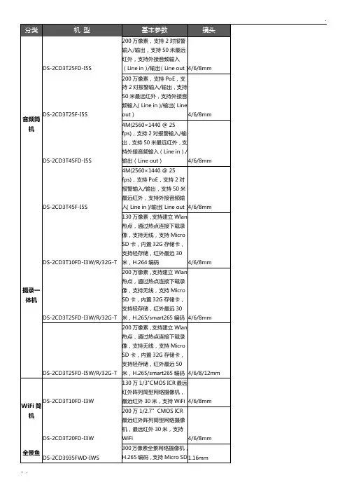


Key FeatureIndoor Station●UI V2.0: User friendly design●7-inch colorful touch screen with resolution 1024 × 600●Standard PoE●Stores messages and captured pictures in the TF card●Remote unlocking via the client software or the mobile client ●Views live videos of door stations and linked cameras●Supports wireless networkDoor Station● 2 MP HD video intercom function●Access control function●Noise suppression and echo cancellation●H.264 video compression●Low illumination●Tampering alarm●Fisheye camera with IR supplement light●Supports sub-modules'access (max. 8)●Nametag customization●Easy to extendSpecificationsIndoor StationModel DS-KH6320-WTE1System Memory 128 MBFlash 32 MBOperation system Embedded Linux operation systemDisplay Display screen 7-inch colorful TFT LCD Display resloution 1024 × 600 Operation method Capacitive touch screenAudio Audio input Built-in omnidirectional microphone Audio output Built-in loudspeakerAudio compression standard G.711 UAudio compression rate 64 KbpsAudio qualityNoise suppression and echocancellationNetwork Wired network 10/100 Mbps self-adaptive network Wireless network Wi-Fi 802.11b/g/nNetwork protocol TCP/IP、SIP、RTSPNetwork interface 1 RJ-45 10/100 Mbps self-adaptive Alarm input 8-ch alarm inputsRelay output 2TF card Max to 32 G, SD 2.0 or lower version RS-485 1General Power supplyIEEE802.3af, standard PoE12 VDC/1 APower consumption ≤ 6 WWorking temperature -10 °C to 55 °C (14 °F to 131 °F) Working humidity 10% to 90%Dimensions (W × H × D)200 mm × 140 mm × 15.1 mm (7.9"× 5.5" × 0.6")Door StationModel DS-KD8003-IME1System parameters Processor Embedded MCU Processor Operation system Embedded Linux operation system Operation method Physical buttonVideo parameters Video compression standard H.264ResolutionMain Stream: 1920 × 1080Sub Stream: 720 × 480 BLC SupportedDNR SupportedWDR Supported Anti-flicker 50 Hz, 60 HzField of view Horizontal : 180°Vertical : 96°Audio parameters Audio input Built-in omnidirectional microphone Audio outputBuilt-in omnidirectional (more than85 dB within 20 cm)Audio compression standard G.711 UAudio compression rate 64 KbpsAudio qualityNoise suppression and echocancellationLight supplement Light supplement mode IR supplementNetwork parameters Ethernet 10/100 Mbps self-adaptive Ethernet Network protocol TCP/IP, RTSPAlarm parameters Tampering alarm 1Interfaces Module-connecting 1I/O input 4Debug 1Relay 2 (30 V, 1 A)General Physical button 1Power supply 12 VDC/PoE ( IEEE 802.3af)Power consumption ≤10 WWorking temperature - 40 °C to 60 °C (- 40 °F to 140 °F) Working humidity 10% to 95%IP protection level IP65Installation Flush mounting, surface mounting Dimensions (W × H × D)98 mm × 99.8 mm × 43.9 mm (3.86"× 3.93" × 1.73")Typical ApplicationPhysical InterfaceIndoor StationNo. Description No. Description1 Screen 5 TF Card Slot2 Microphone 6 Alarm Terminal3 Network Interface 7 Reserved4 Loudspeaker 8 Power TerminalDoor StationNo. Description No. Description1 Microphone 6 Nametag2 Low Illumination IR Supplement Light 7 TAMPER3 Built-in Camera 8 Network Interface4 Loudspeaker 9 Module-connecting Interface (output)5 Call Button 10 TerminalsAvailable ModelDS-KIS602。

智能数字式显示仪表(使用说明书)全电脑数字自动校准多种输入信号自由设定多种外形尺寸可供选择软硬件看门狗,稳定、可靠宽范围超强开关电源目录1、概述 (4)1.1主要特点 (4)1.2仪表维护 (5)2、型号定义 (6)3、技术规格 (9)3.1基本技术规格 (9)3.2选配件技术规格 (11)4、安装与接线 (13)5、参数速查表 (18)6、操作 (23)6.1面板及按键说明 (23)6.2参数设置说明 (24)6.3参数设置方法 (24)7、功能及相应参数说明 (26)7.1测量及显示 (26)7.3报警输出 (30)7.4变送输出 (32)7.5通讯接口 (33)7.6打印接口及打印单元 (35)8、调校 (37)9、输入信号故障处理 (38)10、抗干扰措施 (39)1、概述1.1主要特点◆人性化设计的操作方法,易学易用,并且不同功能档次的仪表操作相互兼容。
◆包含国际上同类仪表的几乎所有功能,通用性强,技术成熟可靠。
◆提供多个型号,无论是要求功能强大,还是要求价格经济,都能获得满意的选择。
◆全球通用的100 -240VAC 输入范围开关电源或24VDC 电源供电,并具备多种外型尺寸供客户选择。
◆输入采用数字校正系统,内置常用热电偶和热电阻非线性校正表格,测量精确稳定。
◆具有多类型输入功能,一台仪表可配接不同的输入信号(热电偶、热电阻、线性电压、线性电流、线性电阻等,无需人工跳线仪表自动识别)大大减少了备表的数量。
◆采用先进的模块化结构,提供丰富的输出规格,能广泛满足各种应用场合的需要,交货迅速且维护方便。
◆全透明、高速、高效的网络化通讯接口,实现计算机与仪表间完全的数据传送和控制。
独有的控制权转移功能使计算机可以直接控制仪表的报警输出和变送输出。
读取一次测量数据的时间小于10ms。
提供测试软件,组态软件和应用软件技术支持。
◆产品经第三方权威机构检测获得CE 认证标志,抗干扰性能符合在严酷工业条件下电磁兼容(EMC )的要求。
DS2100系列说明书DS2100系列DVB误码率场强仪使用说明书Ver 1.0天津市德力电子仪器有限公司天津市德力电子仪器有限公司制造地址:中国天津市南开区宜宾道40号(300113) 服务电话:(022)27631088 27631288传真:(022)27645002电子邮件:deviser@公司主页:这台仪器售出后保修18个月,生产商或代理商负责必要的调校或检验工作,仪器经校准检验合格后才装箱,发还给用户。
用户的职责是:按照说明书来使用这台仪器,假如要维修,就把它送往本公司或指定代理维修站。
一般说来于保修期内,一切非人为使用不当的故障,当由德力公司免费维修。
用户需支付将产品退回至维修部门的运费和保险费,而将维修好的产品交付给用户的费用则由德力公司或指定代理维修站支付。
本公司为本产品设计的软件和硬件正确安装到仪器上后,仪器将执行它的编程指令。
但本公司不保证仪器的各种操作不间断或不出现错误信息。
保修只限于仪器,并不涉及使用不当而导致其它设备、人命及财产的损失。
- 1 -对于不正确的使用或不充分的维护(包括用户附加的软件或接口),及用户自行拆机,本公司将不予保修。
在18个月保修期内,校验、维修服务、咨询是免费的,18个月后将收取适当的材料及维修服务费。
下列各项不属保修范围:①随机赠送的电池及充电器。
②由于机械外力(撞击、跌落等)造成面板、开关、装置及机壳的变形损坏并涉及到内部器件的故障。
③擅自拆开仪器试图修理的。
④装运时的损毁(在仪器包装发运给用户时,已由发货人购买了运输保险)。
用户提货时,应当场查验,如遇仪器损毁,请向货运公司或部门交涉。
只有收货人(接收仪器的个人与单位)才有权就运输损毁向承运者提出赔偿要求。
- 2 -请小心开箱,并注意将全部附件放在一个地方,以防遗失。
我们建议最好保存原包装箱和包装材料,以备将来搬运时使用。
注意只有经过维修培训的人员才能维护本仪器。
为了避免损坏,未经过培训人员不应进行仪器的维护修理。
The sensor can be positioned by means ofthe three housing’s holes using two screws(M4x25 or longer, 1.5 Nm maximumtightening torque) with washers.Various orientable fixing brackets to easethe sensor positioning are available(please refer to the accessories listed inthe catalogue).The operating distance is measured fromthe front surface of the sensor optics.The M12 connector can be oriented at two different positions using thespecific fastening spring and rotating the block of 180°.CONNECTIONSThe connections are compliant to the EN 60947-5-2 standard.N.C. OUTPUTN.O. OUTPUT0 VTEST +TEST -0 VM12 CONNECTOR14DIMENSIONSTECHNICAL DATAPower supply: 10 … 30 Vdc (limit values)Ripple: 2 Vpp max.Current consumption(output current excluded): 35 mA max.Outputs: PNP or NPN; 30 Vcc max.(short-circuit protection)Output current: 100 mA max.Output saturation voltage: ≤ 2 VResponse time: 0.5 ms mod. B01/B51/T51; 1 ms mod. C01/C11/F01Switching frequency: 1 kHz mod. B01/B51/T51; 500 Hz max. mod. C01/C11/F01Indicators: OUTPUT LED (YELLOW)STABILITY LED (GREEN) (mod. B01/B51/C01/C11/F01)POWER ON LED (GREEN) (mod.G00)Setting: sensitivity trimmer (mod. B01/B51/C01/C11/F01/T51)Operating temperature: -25 … 55 °CStorage temperature: -25 … 70 °CElectrical shock protection: Class 2Operating distance (typical values): B01: 0.1…6 m on R2B51: 0…3m on R2 (0…2 m on R2 mirror rejection)C01: 1…90 cmC11: 5…200 cmF01/G00: 0…20 mT51: 0…1.5 m on R2Emission type: RED (660 nm) mod.B01/B51/C01/T51; INFRARED (880 nm) mod.C11/G00Ambient light rejection: according to EN 60947-5-2Vibrations: 0.5 mm amplitude, 10 … 55 Hz frequency, for every axis (EN60068-2-6)Shock resistance: 11 ms (30 G) 6 shock for every axis (EN60068-2-27)Housing material: ABSLens material: PMMA window, polycarbonate lens / glass window and lens mod. B51/T51Mechanical protection: IP67Connections: 2 m cable ∅ 4 mm / M12-4 pole connectorWeight: 90 g. max. cable vers. / 40 g. max. connector vers.SETTINGTurn the trimmer to the intermediate position C, between the twopositions A and B. The green LED must be ON.TEST FUNCTION (S60 (00)The TEST+ and TEST- inputs can be used to inhibit the emitter andverify that the system is correctly operating.The receiver output should switch when the test is activated while thebeam is uninterrupted.The inputs activating voltage range is 10 … 30 Vdc, whilst respecting thepolarity.The emission is switched off connecting TEST+ to Vdc and TEST- to0V.DECLARATION OF CONFORMITYWe DATALOGIC AUTOMATION declare under our sole responsibilitythat these products are conform to the 2004/108/CE and successiveamendments.WARRANTYDATALOGIC AUTOMATION warrants its products to be free fromdefects.DATALOGIC AUTOMATION will repair or replace, free of charge, anyproduct found to be defective during the warranty period of 36 monthsfrom the manufacturing date.This warranty does not cover damage or liability deriving from theimproper application of DATALOGIC AUTOMATION products.Datalogic and the Datalogic logo are registered trademarks of DatalogicS.p.A. in many countries, including the U.S.A. and the E.U.826001333 Rev.D© Copyright Datalogic 2007-2009 Phone:800.894.0412-Fax:888.723.4773-Web:-Email:***************。
DS201 User’s ManualContentsI Product Intro (2)II General Safety Rules (2)III Major Functions (2)IV Operation Precautions (3)V General Inspection (3)VI Functional Inspections (3)VII Battery Recharging Instruction (3)VIII SD Card Storage Instruction (3)IX Firm ware Upgrades (3)X Product Familiarization (5)1. Interface and Buttons (5)2. Screen (5)XI Measurement Operation Instruction (6)1. Parameter Area Intro (6)2. Measurement Area Intro (6)3. Specific Parameters Intro (6)Hidden two waveform operation line (10)Zero voltage calibration (13)XII Application Examples (15)1. Example One: Measure Simple Signal (15)2. Example Two: Measure with Cursor (16)3. Example Three: Save Waveform Image (17)4. Example Four: Acquire Single Signal (18)5. Example Five: C ompare Waveform Signals (18)I Product IntroDS201 pocket size oscilloscope is a compatible 32bit digital storage oscilloscope. Based onARM-M3, it’s equipped with 320*240 color display, SD card, USB port and recharging function. It’s compact, simple to operate; meets the basic demands of school lab, electric furniture repairmen and electric engineering.II General Safety RulesTo ensure your safety & avoid any damages to the product/connected devices, please read the following safety rules carefully. To avoid any possible dangers, please use this product according to the rules.Use appropriate power cord. Please use dedicated power cord which is certified in the country/region.Connect/disconnect properly. Do not plug/unplug when the probe(s)/test lead(s) is connected to the power source. Before you plug/unplug the current probes, please disconnect the power to the circuit-under-test.Observe all terminal ratings. To avoid fire/electric shock, please don’t measure signal with DC100V or above, or the device might be destroyed. Please read the manual carefully to know the detailed info of related ratings before connection.Please do not operate in humid environment.Please do not operate in inflammable/explosive environment.Please keep the surface of the product clean and dry.III Major FunctionsIV Operation Precautions▌Temperature:Working condition:+0℃to +500℃Non-working condition:-20℃to +60℃:▌Humidity:Working condition:High temperature:40°C - 50°C,0%-60%RHWorking condition:Low temperature:0°C - 40°C,10%-90%RHNon-working condition:High temperature:40°C- 60°C,5%-60%RHNon-working condition:Low temperature:0°C - 40°C,5%-90%RHV General InspectionWhen you get a new DS201, it’s suggested to inspect the product by the following steps:1.Inspect for damage caused by shipping.If the carton/plastic protection pad is seriously damaged, please keep the package until the product and accessories pass the inspection electrically and mechanically.2.Inspect the productPlease contact the company if the following problems occur: 1) product surface is damaged, 2) product doesn’t work properly, 3) product does not pass performance test.If the damage is resulted from shipping, please keep the package and contact the transportation department/ RIGOL distributor who is in charge of this service, for repair or exchange.VI Functional InspectionMake a quick functional inspection to ensure the product is working soundly. Please perform following steps: 1.Turn on the power supply, access homepage of the oscilloscope.2.Connect the oscilloscope with standard signals (e.g. square wave 20KHz,Vpp=5V), set the switch on probe tip as 1X, plug oscilloscope probe to the jack.Check whether the measured signal value is the same as the standard value; it can be calibrated if the margin is small.VII Battery Recharging InstructionWhen the battery sign shows as “”, or when the display is dim, please recharge in time. The product can be power on or off while recharging.VIII SD Card Storage InstructionInsert SD card into the slot before using SD card to store waveform images. This product supports SD Card storage. (Max. memory: 2G)IX Firmware UpgradeTo upgrade firmware, please perform following steps:1. Open web to access , download the latest applicable firmware to your PC.2. Simultaneously press “—” of DS201 and turn on power supply, enter DFU firmware upgrade mode.3. Use USB to connect DS201 to your PC, a removable disk named DFU V3_11_A will appear on your PC.Copy the hex firmware to the root directory of your disk. After the extension of the firmware changes from “hex” to “rdy”, restart DS201, thus firmware is upgraded.X Product Familiarization1. Interface & Buttons2. ScreenThe screen display is depicted as below:NOTE:There are corresponding colors for items in Parameter Area and Measurement Area.XI Measurement Operation Instruction1.Parameter Area Intro/2.Measurement Area Intro3.Choose the items in parameter area through “+” or “_”. Pres s “M” to access parameter setting menu, use “+” and “_” to choose the parameter item, and then use “| ” and “ |” to change the parameter value of the place where the cursor blinks.(1)Annotation of Yn parameters(2)Annotations of Xn Parameters(3)Annotations of Tr parameters(4)Annotations of Me Parameters(5)Annotations of Ex ParametersSet the cursor to the "EX" option, press the "M" pop-up window, select "Ext Refn" option, then Through "| " or " |" change cursor blink parameter values for the "Off", the two waveform operation line (purple line)Be hidden, as shown in the figure below.(7)Annotations of Sn ParametersOscilloscope Calibration:Press ||Zero voltage calibration: as the chart, "1.0 V" gear, zero line is inaccurate and head for the "PO - 17", needs to be calibrated.The calibration Steps:1. Through "+" or "-"button to move the cursor option" Ca "option, press"M "pop-up" Calibration"Window.2.Press " ||" button to enter the calibration options window.3.Select "Cal Zero" option, by | or" | "change the cursor blink in the parameter value is adjusted for" PO 0.0 " Zero calibration line, line with the arrow to a level.4.The calibration after the zero line, we need to save the Settings after calibration. By "+" or"-” button tomove the cursor option "Yn" option, long press " ||" button, the pop-up."Save ParamTab?"Window, press the " ||" button to save the calibration.5.The other gear have zero line position error, the calibration in accordance with theabove method.XII Application Examples1.Example One: Measure Simple SignalObserve one unknown signal in a circuit, quickly measure & display the signal’s frequency & peak-to-peak value. Please operate according to following steps:Connect the channel probe to the detection point of the circuit.Set the Channel mode as AUTO, adjust the (Horizontal) time calibration and (Vertical) voltage calibration, make sure the signal displays clearly.Adjust Threshol horizontal triggering position to make signal display stable.Use “+”or “-” to choose Me items in Measurement Area,then press “M”, use “| ”or “ |” to choose the signal parameters that need analysis, e.g. Freq(frequency), Duty(dutyfactor), Vpp(peak-to-peak voltage)etc., the measured value will be displayed at the lower right corner of the screen, as shown in the image below:2.Example Two:Measure with CursorA cursor can be used to measure the time and voltage of the waveform very quickly. (1)Measure the cycle of signal sourcePlease operate according to the following steps:Use “+” or “-” to choose Yn items in Measurement Area.Press “M”Use “| ” or “ |” to choose CursorV1Use “+” or “_” to adjust the position of CursorV1 to the crest.Use “| ” or “ |” to choose CursorV2Use “+” or “_” to adjust the position of CursorV2 to the valley.And get:△V=1.00mS i.e. the cycle of signal source. As shown in the image below:(2)Please operate according to following steps:Use “+” or “_” to choose Yn items in Measurement AreaPress “M”Use “| ” or “ |” to choose CursorV1Use “+” or “_” to adjust the position of CursorV1 to the crestUse “| ” or “ |” to choose CursorV2Use “+” or “_” to adjust the position of CursorV2 to the valleyAnd get:△V=2.08V. i.e. the cycle of signal source, as shown in the image below:3. Example Three :Save waveform imageSometimes waveform images need to be archived or analyzed on PC platform. Please operate according to following steps:Use “+” or “_” to choose the Fn items in Measurement Area, press “M ”, use “| ” or “ |”to choose Save Bmp, and then use “| ”or “ |” to choose the file name on the lower right corner of the screen ,e.g.Save000.BMP ,as shown in the image; and then press “ ||” to save it to the built -in U disk.Just copy the image to your PC, and you can analyze the waveform image.4.Example Four: Acquire Single SignalIt’s the superiority and feature of digi tal oscilloscope to easily aquire non-periodic signals like impulsion and sentus. To aquire a single signal, you need a priori knowledge of it to set trigger level & trigger edge. E.g. if impulsion is a TTL PWL logic signal, trig level should be set as 2V, trig edge as rising edge trig. If the signal is not stable, it’s suggested to observe in a normal triggering mode to define trig level & trig edge.Operation steps are as follows:Connect the channel probe to the detection point of the circuit.(rising edge trigger)Triggering setting: DC Coupling.Adjust proper triggering PWL.Use “+”or “_”to choose Tr items in Measurement Area, press “M”; use “| ”or “ |”to choose Syncmode,and then use “| ”or “ |”to choose single touch mode, wait for the signal that match the triggering condition to show up. If there is one signal reaching the preset PWL, it will be sampled and displayed on the screen. As shown in the picture.5. Example Five: Compare waveform signalsPlease operate according to following steps:Input standard signal waveform to the channel, chose Data in EX, and then choose Save Dat 01 to save the waveform, as shown in the image below.Input unknown to-be-measured signal to the channel, choose Load Dat01→EX→Data, and then the to-be-compared waveforms are shown on the screen simultaneously, as shown in the image.。
一、概述GF-D600型半自动生化分析仪是引进国外先进技术,综合国内外生化检验发展的情况而设计、生产的分析仪器。
仪器由微电脑控制,大屏幕彩色液晶中文显示,集中文打印、显示及生化分析为一体,精度高、重复性好、功能齐全、微量快速,可用于医院化验室对血糖、血脂、肝功、肾功、离子等生化项目的测定。
仪器采用中文菜单提示,实现人机对话,操作简单、易学。
能进行非线性终点法、线性终点法、样品空白法、速率法、两点法、单双波长法、吸光度法等方法学的应用。
可随时打印查阅所储存的样品结果,根据需要打印出单项目报告单、单样品报告单及综合报告单,是各级医疗单位理想的检验设备之一。
二、仪器的主要规格与技术参数1、波长选择器:光栅分光式2、光源:12V 30W卤钨灯3、波长范围:330—800nm,波长连续可调,任意设置4、波长准确度:±2nm5、波长重复性:≤1nm6、光谱带宽:≤6nm7、吸光度范围:-0.3~3.0Abs8、线性误差:±5%9、吸光度重复性:≤0.005Abs10、分辨率:0.001Abs11、温度控制:室温﹑25℃﹑30℃﹑37℃任选12、温控精度: ±0.5℃13、进样系统:吸液量100ul~2000ul,任意设置。
14、测试方法:(1)线性终点法(2)非线性终点法(标准曲线法)(3)两点法(固定时间法)(4)速率法(动力学法)(5)单、双波长法(6)吸光度法(7)样品空白法15、项目存储:可存储200个项目参数,已固定存储72个项目。
16﹑键盘:薄膜轻触键17﹑显示方式:带背光的10.4寸彩色液晶中文显示18﹑打印机:内置热敏打印机,打印纸宽为110mm。
19、环境温度范围:0~+40℃20、环境相对湿度:0~90%21、稳定性:≤0.002Abs/h22、样品用量:1~50ul(根据试剂要求)23、比色池:流动式,容量32ul,光径10mm。
24、交叉污染:≤2%25、程序设置:开放式编程26、试剂:开放式使用,任选。
ds-k1f600-d6e说明书
1 、数据采集器主要应用于仓储物流管理中,由于其行业特性数据多变复杂,人为输入失误无法完全避免所以采用数据采集器来解决。
2 、它是通过PC端程序和数据采集器本身终端程序来共同完成的,一般通过条码来实现数据采集。
3 、采集后数据会暂存在采集器本身上,待采集完毕或汇总时要通过数据线与PC同步。
4 、并将所采集的数据信息上传到PC端软件中。
5 、一般做条码软件的厂商都可以针对不同品牌做相应开发。
6、同时,物品信息通过直接上传计算中心。
采用采集器设备后数据记载的各环节实现了数据的自动登录,避免了数据的从新录入问题。