艾默生推出用于船舶和电力应用的重质燃油黏度计
- 格式:pdf
- 大小:89.82 KB
- 文档页数:1
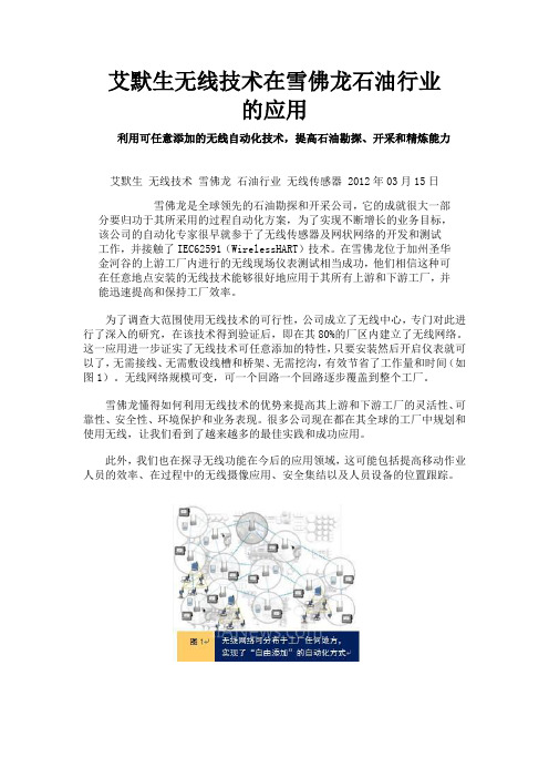
艾默生无线技术在雪佛龙石油行业的应用利用可任意添加的无线自动化技术,提高石油勘探、开采和精炼能力艾默生无线技术雪佛龙石油行业无线传感器 2012年03月15日雪佛龙是全球领先的石油勘探和开采公司,它的成就很大一部分要归功于其所采用的过程自动化方案,为了实现不断增长的业务目标,该公司的自动化专家很早就参于了无线传感器及网状网络的开发和测试工作,并接触了IEC62591(WirelessHART)技术。
在雪佛龙位于加州圣华金河谷的上游工厂内进行的无线现场仪表测试相当成功,他们相信这种可在任意地点安装的无线技术能够很好地应用于其所有上游和下游工厂,并能迅速提高和保持工厂效率。
为了调查大范围使用无线技术的可行性,公司成立了无线中心,专门对此进行了深入的研究,在该技术得到验证后,即在其80%的厂区内建立了无线网络。
这一应用进一步证实了无线技术可任意添加的特性,只要安装然后开启仪表就可以了,无需接线、无需敷设线槽和桥架、无需挖沟,有效节省了工作量和时间(如图1)。
无线网络规模可变,可一个回路一个回路逐步覆盖到整个工厂。
雪佛龙懂得如何利用无线技术的优势来提高其上游和下游工厂的灵活性、可靠性、安全性、环境保护和业务表现。
很多公司现在都在其全球的工厂中规划和使用无线,让我们看到了越来越多的最佳实践和成功应用。
此外,我们也在探寻无线功能在今后的应用领域,这可能包括提高移动作业人员的效率、在过程中的无线摄像应用、安全集结以及人员设备的位置跟踪。
业务挑战。
对于上游工厂来说机会显而易见,离岸平台需要更多更全的信息,以获得更好的采油效率,因为发现一口油井可能需要10年,而让油井产油还要10年,所以必须让油井持续高效地产油才能收回巨大的投入。
在拥挤的平台上和浮式储油船上所采用的自动化方案必须体积小、重量轻、安装和使用方便。
海上油田也希望能够延长油井寿命和提高产量。
需要通过一些改进来提供更好的采油系统监测,实现输配系统和过程装置的高采收率,为运行中心提供更好的信息来控制分散的油井和设施。

4642 N. RAVENSWOOD, CHICAGO, ILLINOIS 60640-4510TELEPHONE: 1-773-561-2349FAX: 1-773-561-3130Model BD-60 AUTOMATIC SENSING INSULATION LEAK DETECTOROPERATING MANUALSECTION 1--GENERAL INFORMATION1.1 Description1.1.1 This automatic Sensing Insulation Leak Detector is an electronic, self-sensinginstrument with a solid-state spark tester. Several model variations areavailable. All of them will detect small holes in:* plastic, glass, or rubber linings of metal tanks* linings of metal pipes, valves and fittings* thin coatings or paint on metal or concrete surfaces1.1.2 Once adjusted for the thickness of a coating or lining, and for the electrodeused, an audible tone and a light will automatically indicate when the probe is swept over a spot where a pinhole, crack, or tear is located.04/111.1.3 The electronics of the system are contained in a metal cabinet, with a slopedvisor to increase the visibility of the indicator lamps if used in a well-lit area. Ithas an 8-ft. line cord, and the circuitry is fused. A hand-held generator isattached to the front panel via a 6 ft. cord. Each model is furnished withseveral electrodes. Refer to the Packing List in Section 1.3 for the type ofelectrodes furnished with the specific model ordered. A variety of accessoryelectrodes are also available.1.1.4 The Model BD-60 is the standard model operating from 115V. The Model BD-60V is identical to the Model BD-60 except that operation is from 230 volts. It issupplied with a line cord and plug polarized (per US Standards) for this voltage.1.1.5 The Model BD-60T is intended for use for Tank Lining Testing. It is the same asthe Model BD-60, except that it comes with accessory electrodes appropriate fortank lining testing. The Model BD-60TV is identical to the Model BD-60T exceptthat operation is from 230 volts. It is supplied with a line cord and plug polarized(per US Standards) for this voltage.Four models are available for different input voltages:Model BD-60, 115 V, 50/60 Hz Model BD-60V, 230 V, 50/60 HzModel BD-60T, 115 V, 50/60 Hz Model BD-60TV, 230 V, 50/60 Hz1.2 SpecificationsTester Voltage Output – 2,000 to 40,000 voltsThe following table is a typical range, but will vary from unit to unit, and isdependent upon which electrode is being used. A certificate of calibration, providedwith each unit, will give the actual outputs for that particular unit.POSITION N0. 0 2 4 6 8 10 Voltage 2,000 6,000 16,000 29,000 37,000 40,000 Voltage Waveform – pulsated DC signal; Pulse Width Frequency – 400 to 500 kHzTrip current levels: Minimum: 0.5 mA; maximum: 25 mA, depending upon voltageand sensitivity settings.Input Electrical Requirements – 50/60 Hz, single phaseModel BD-60, BD-60T: 115 V, Model BD-60VAC, BD-60TV: 230 VAC Dimensions – Power Source: 9-1/4 x 4-3/4 x 7 in. high (23.5 x 12.1 x 17.8 cm)Probe Handle: 2 x 10 in. without electrode (5.1 x 25.4 cm) Weight: Net, 8.8 (4 kg); Shipping, 10.9 lbs (4.9 kg)1.3 Packing List1.3.1 Carefully remove the instrument and accessories from the packing material. Check allparts against this Packing List. Notify Electro-Technic Products, Inc. of any shortages immediately.1.3.2 Packing List for Models BD-60 (Product No. 16001) or BD-60V (Product No.16021xx):1 011-0019-1 Handle Assembly1 12101 Electrode Tip Standard1 12201 Electrode Tip, Spring1 12461 Electrode Shorting Block1 085-0044-3 Instruction Manual1 X004-10 Certificate of Calibration1.3.3 Packing List for Models BD-60T (Product No. 16031) or the Model BD-60TV (ProductNo. 16021xx):1 011-0019-1 Handle Assembly1 12101 Electrode Tip Standard1 12201 Electrode Tip, Spring1 12131 Electrode, 12 in. T-Tip1 12141 Electrode, Fan Tip3 12461 Electrode Shorting Block1 085-0044-3 Instruction Manual1 X004-10 Certificate of Calibration1.4 Accessory EquipmentAccessory Electrodes for the Model BD-6012201 Spring Tip12121 T-Tip12131 T-Tip, 12 in. Wide12141 Fan Tip12401 Brush Tip4 in. Wide 4 in. Wide12421 Brush Electrode, 8 in. WideAccessory Peak Voltage CalibratorAccessory Electrode Extension Rods12441 Electrode Extension, with 12141 Fan-Tip Electrode Shown in use. Note hand-hold grip. Three Electrode Extension Rods and available, all include hand-hold grips as shown above. They can be used with all of the accessory electrodes shown above.12441 Electrode Extension, 4 ft., 1244101 Electrode Extension, 10 ft, 3 sections.124101-1 Electrode Extension, 12 ft., 3 sectionsAccessory Electrodes for Testing Outer Diameters of PipesBrush Electrodes, (SKU Series 12471) ½, 1, 1.5, 2.5, 3, 4 in. Eachelectrode has a hand grip to move the electrode over the length of thepipe.Accessory Electrodes for Testing Inner Diameters of PipesIndividual brush electrodes are available for inner diameters of ¾ , 1, 1.5, 2, 3 and 4 in. They require a Electrode Extension Rod, described above.Individual electrode discs, for testing inner diameters of 5, 6, 8, 10,12, 14 and 16 in diameters are available. They require the electrodedisk attachment and guide roller for a given pipe inner diameter.The BD-80 handle is built in. An assembly for testing 6 in. inner pipelinings is illustrated at the left. Contact Electro-Technic for furtherdetails and a price quotation.1.5 Warranty Repair / Replacement Information1.5.1 If the unit requires repair, forward it freight prepaid to Electro-Technic Products, Inc.Please request a Return Authorization Number prior to sending it in.1.5.2 Electro-Technic Products, Inc. reserves the right to repair or replace any unit sent infor warranty repair.1.5.3 If found to be out of warranty, or damaged due to improper use, it will be repaired for aminimal labor and parts charge. We will advise the customer prior to any work being done.SECTION 2--INSTALLATION2.1 Installation2.1.1 Locate the Model BD-60 within 6 ft. (1.8 m) from the surface to be leak tested.2.1.2 The Generator Handle is terminated with color-coded, shielded banana plugs. Attacheach to the matching binding posts on the front panel.2.1.3 With the Power Switch in the OFF position, insert the line cord plug into its matchingthree wire grounded receptacle. This insures that the chassis is grounded. Operation in any other way will result in a potential shock hazard and may affect the performance of the instrument. Never use a line cord plug adapter.2.1.4 If you are testing lining that are at least ¼ in. (6 mm) thick, the electrodes furnished, orpurchased will require installation of a 12461 shorting block, except for the 12201 Spring Tip Electrode. All other Electro-Technic electrodes have a plastic spacer in between the electrode tip and the base that fits into the socket of the Generator Handle. This spacer separates the two metal parts. A spark must jump this gap before the voltage can be applied to the electrode tip. This spacer/air gap effectively isolates the electrode tip from line voltage in the unlikely event of a short in the Tester. This is important for the Model BD-10A and BD-10AS High Frequency Generators, but an isolation transformer provides protection for the Model BD-60.Push the black plastic block over the white plastic spacer of the electrode. Make certain the spring clips of the block make contact with both metal parts of the electrode..2.1.5 For testing lining greater than ¼ in. (6 mm) the Shorting Block need not be installedon the electrode. To install the electrode, with or without the shorting block, press it into the tip of the generator handle. To remove, grasp its base firmly, and with a gentle twisting motion, pull out from the generator tip. Never insert or remove the electrode while power is on. Never remove the electrode by screwing it out.SECTION 3—OPERATION.3.1 Front Panel Operating Controls3.1.1 Power ON/OFF Switch. A toggle switch located in the lower left hand corner.3.1.2 Sensitivity Adjust Knob. Located in the middle left side. It adjusts or “tares” thesensitivity of the circuitry as it detects the induced current of the corona over a good surface relative to the current when a spark arcs through a pinhole or flaw to the metal subsurface. It is numbered 0 through 10. Turing it clockwise increases the sensitivity.3.1.3 Increase Voltage Adjust Knob. Located in the middle right side. It sets the propervoltage applied to the electrode for the application. It is numbered 0 through 10. Turing it clockwise increase the voltage. This is an important setting, especially when testing thin coatings.3.2 Front Panel Status Indicators3.2.1 Test Indicator Lamp. An red lamp located at the top, left center. It is lit when a test is inprogress, but is off when a fault (leak) is encountered.3.2.2 Fault Indicator lamp. A red lamp located at the top, right center. It works in conjunctionwith the Test Indicator Lamp. It is lit when a fault (leak) is detected, and remains lit for about 3 to 4 seconds. During this time, the test is interrupted, and no voltage is applied to the electrode.3.2.3 Fault Indicator Alarm. A horn located in the middle of the panel. It sounds an alarm forabout 3 to 4 seconds when a fault is detected.3.3 Front Panel Terminal Connections3.3.1 Output to Probe Terminals. Two color-coded binding posts, black and red, located atthe lower right corner. These provide power to the Generator Handle and its electrode.The illustration above show the Generator Handle connected to these terminals.3.3.2 Ground Terminal. A black binding post located at the lower center of the panel. Thisprovides electrical earth ground through the grounded power line cord. When testing the lining or coatings of a small metal object, the metal may require connection to this terminal. For better accuracy, if the part under test can be grounded to the BD-60 chassis terminal, then it should be. If not, a higher voltage may be needed to perform the test.3.4 Calibration3.4.1 The Model BD-60 circuitry is factory calibrated, and a Certificate of calibration isfurnished. Yearly recalibration is recommended. Factory calibration service is available for a nominal charge. It includes test data for all output positions with a number of electrodes, and is traceable to a NIST standard. Request a Return Authorization Number prior to returning to the factory for calibration.3.4.2 The following protocol is used when factory calibration is preformed.Position 0 2 kV ± 1 kVPosition 2 6 kV ± 3 kVPosition 4 16 kV ± 3 kVPosition 6 29 kV ± 3 kVPosition 8 37 kV ± 3 kVPosition 10 40 kV ± 3 kV, but at least 1 kV higherthan position 83.5 Adjustment for Leak Detection of Coatings3.5.1 A coating is a non-conducting film generally in the range of 10 to 20 thousands of aninch, or 10 to 20 mils. Coatings generally have a break down voltage of between 200 to 400 V/mil. The manufacturer of the coating should provide the exact break down voltage for the coating. For a 10 mil coating, the voltage setting should be between 2 and 4 kV, to compensate for coatings which may typically not of uniform thickness, or for coatings with a pebbled-type surface.3.5.2 To adjust the model BD-60 for coating leak detection application, select an area thatrepresents the average thickness of the coating to be tested, and make certain that this test surface does not have any pinhole leaks or similar flaws. Also mark an area that has a know pinhole. Better yet, create a test medallion of small area with thesame coating thickness and metal substrate as the part to be tested, and create apinhole in one area of this medallion.3.5.3 Turn the Sensitivity Adjust Knob completely counterclockwise to the “0” position.Set the Voltage Adjust Knob to the “0” position, which is approximately 2 kV. Usethe 12201 Spring Tip Electrode, or any other electrode with a shorting blockinstalled. Turn power ON, and position the electrode over an area that is free ofpinholes. Then position the electrode over a known pinhole, and then turn theSensitivity Adjust clockwise until the Fault Lamp is lit. Try to reduce this setting byone position and repeat the test.3.5.4 If the Fault Lamp does not light even for the maximum position 9 of the SensitivityAdjust Knob, then the voltage is set too low. Repeat Step 3.5.3, but with the Voltage Adjust Knob in position “2”, which will give a voltage of approximately 8 kV.3.5.5 If the voltage is set too high for very thin coatings, there is a risk that the corona ishigh enough to exceed the dielectric break down of the coating material, causing a pinhole to be created, especially if the electrode lingers for too long over a singlepoint of the coating. If the electrode is held above the surface, the total voltagerequired to set the coating will be greater than if it makes contact with the surface, as the spark must then travel though both the air (the distance the electrode is heldabove the surface, and the distance through the coating. This is why it isrecommended that the electrode always makes contact with the surface. Fordelicate coatings, consider using the Model 12141 Fan Tip Electrode, or either one of the brush electrodes, Models 12401 or Model 14241.3.6 Adjustment for Leak Detection of Linings3.6.1 A coating is a non-conducting film generally in the range of 10 to 20 thousands of aninch, or 10 to 20 mils. Coatings generally have a break down voltage of between 200 to 400 V/mil. The manufacturer of the coating should provide the exact break down voltage for the coating. For a 10 mil coating, the voltage setting should be between 2 and 4 kV, to compensate for coatings which may typically not of uniform thickness, or for coatings with a pebbled-type surface.3.6.2 To adjust the model BD-60 for coating leak detection application, select an area thatrepresents the average thickness of the coating to be tested, and make certain that this test surface does not have any pinhole leaks or similar flaws. Also mark an area that has a know pinhole. Better yet, create a test medallion of small area with thesame coating thickness and metal substrate as the part to be tested, and create apinhole in one area of this medallion. If ¼ in. rubber lining is being tested, Electro-Technic has a test medallion, SKU 12191.3.6.3 To set sensitivity, Turn the Sensitivity Knob to the 0 position, and the Voltage AdjustKnob to the 9 position. The breakdown voltage of most linings will be greater than the 40,000 V maximum output of the Model BD-60. Sweep the electrode over thetest medallion over the area without a pinhole, and increase the sensitivity until you reach the 9 position. If the alarm sounds over a good area, this is called a falsetrigger. Then reduce the sensitivity until this false trigger stops. This is then thecorrect setting for the sensitivity.3.6.4 Then sweep the electrode over the lining, or test medallion, and over an area wherea known pinhole is located. The Fault Indicator lamp should light only when theelectrode passes over the pinhole. Once the pinhole is detected, pull the electrode away from the pinhole and wait for the logic on the Model BD-60 to reset back to the test mode. This delay should be approximately 2 seconds.3.6.5 Some linings have cracks or tears that are at an angle, rather than perpendicular, toits surface. Increasing the voltage output is required to locate this type of defect.See the Figures 1a, and 1 b below. Figure 1a shows a linings without a pinhole. No spark discharge is seen. In Figure 1b, when a pinhole is present, a spark discharge can be seen between the electrode and the pinhole. The pinhole depicted isoblique, and is longer than the thickness of the linings. The voltage must beadjusted higher to see these types if pinholes.Photo at left shows a pinhole located in a sheet ofrubber with a metalbacking, using the12141 Fan Tip ElectrodeNOTEThe Adjustment Procedure must be repeated whenever the following is true:1) The electrode is changed to a different type.2) The material, or thickness or the thickness of the coating or lining changes.3.7 Operation3.7.1 When power is turned on, the circuitry will go into self-test. The Fault Lamp will be litinitially, and the Horn may sound, depending upon the Sensitivity Adjust position. After about 2 seconds the Test Indicator lamp should come on, and the Fault Indicator lamps and Horn should both be off.3.7.2 Once the Model BD-60 is properly adjusted, sweep the electrode over the surface to betested. The corona generated at the tip the electrode is what seeks out a minute pinhole or crack, breaking down into a spark which penetrates the pinhole and strike the metal or conductive surface below. See the figures above.3.7.3 Understanding the nature of the typical defect encountered is important for properoperation. A very small pinhole with a diameter in microns will require a higher voltage to detect than larger cracks or seam tears, due to the added insulation properties of a minute pinhole, especially if it oblique to the surface.3.7.4 Grounding of the metal object whose coating or lining is being tested may be requiredfor smaller object. If grounding is required, it is recommended that the object be connected directly to the Ground Terminal on the front panel of the Model BD-60, using as short a wire as possible.3.7.5 At settings of the Increase Voltage Adjust above 5, there may be a crackling sound atthe electrode tip. This is normal. It is due to corona discharge. If the operator accidentally touches the electrode tip, the Fault Indicator Lamp will come on.3.7.6 The Model BD-60 is designed for continuous operation under normal conditions, but itis recommended that the power be turned off when not in use, or a hazard may occur.3.7.7 If it is used in an atmosphere where chlorinated products are present, or is used in aplating room, or other similar corrosive environment it is advisable to remove the unit when not in use and store it away from these areas. Prolonged exposure can corrode the metal parts inside the instrument, shortening its service life.3.8 Safety Precautions.3.8.1 Only factory approved electrodes should be used. No other electrodes should be usedwith this device. Never operate without an electrode.3.8.2 Never touch or come in contact with the high voltage output of this device, nor with anydevice it is energizing. The Model BD-60 generates a high frequency, high voltage pulse. A spark to the body will not cause harm, but will cause a slight discomfort, similar to the sensation when a static spark jumps from the finger tip to a metal object after walking across a carpet on a dry day. The output of the Model BD-60 is at a very low current. Also, the skin of the body has a very high resistance to the high frequency current, causing any current to flow harmlessly over the skin.3.8.3 Since its output is 500 kHz, it radiates its energy for a short distance. It may interferewith sensitive electronic devices near by. If a user is wearing a pace maker or similar device, their physician should be contacted prior to using this device. The same should be said for women who are pregnant.3.8.4 A small amount of ozone gas is generated as a by-product. Use in a well-ventilatedarea. Do not use in a confined area where high concentrations of ozone can accumulate.3.8.5 Do not operate around a flammable or explosive environment, as the spark mightignite them. Tanks which contain flammable liquids must be drained, flushed, cleaned, and be completely dry before testing can begin. If used inside a cargo tanker,someone located outside of the tank should always be observing the operator inside. SECTION 4 - CALIBRATION SERVICE.4.1.1 A certificate of calibration is provided with the Model BD-60. Annual re-calibration isrecommended. When sending it back to the factory for re-calibration, request a Return Authorization Number prior to sending it in. Include the handle assembly and any accessory electrode used with the unit. Send it freight prepaid to Electro-Technic Products, Inc., well packed to prevent shipping damage.4.1.2 Specify whether “as received” and “as left” data is required, or only “as left data”. If aunit is received in calibration, then the certificate will so indicate. If the unit require repair to bring the unit into calibration, the “as left” data will be after repair. Our repair department will advise you of the cost prior to any repairs.SECTION 5 - REPAIR AND TROUBLESHOOTING.5.1.1 There are no user serviceable parts inside the unit. In the event that the unitrequires service, send it back to the factory. However, parts are availableseparately, so an experienced electronics technician can make repairs. Thefollowing troubleshooting guide is furnished:CAUTION. Take precautions not to touch any wires, as power to beunit will have to be applied with the cover removed to perform thisoperation.5.1.2 No user serviceable components are located in the Generator Handle.5.1.2 To remove the cover for servicing, disconnect the power cord line from its powersource, and remove the two ¼ in. hex hand screws located on either side of thefront panel. Lay the unit down and carefully lift the front panel away from thechassis. Take care not to damage any of the wires, or their connections, whileremoving or re-installing this panel.- 12 -5.1.3 Check all connections for loose or broken wires. If the pilot light does not come on,check for shorts and for input voltage at the fuse. If fuse is blown, replace it with a ½ A Slo-Blo fuse.5.1.4 If the fuse is Okay, check the power cord for shorts, and replace if necessary. Testthe ON/OFF Switch.5.1.5 If the pilot light comes on, check the transformer for 115 V between the secondaryleads. If you have an extra generator handle, exchange handles.5.1.6 If you should have any further questions, contact Electro-Technic Products, Inc. foradditional technical assistance.SECTION 6 - REPAIR AND REPLACEMENT PARTS.Part Number Description12101Electrode Tip, Standard12201Electrode Tip, Spring, Low Voltage12461Electrode Shorting Block002-0005-1Nut, 10-32, Hex, for Electrode Socket010-0003-1Isolation Transformer, 115 V010-0007-3Choke010-0012-1Step Down Transformer, 230 to 115 V011-0019-1Handle Assembly (High Voltage), with Cord020-0032-1Potentiometer, Sensitivity / Voltage020-2001-3Resistor, 250 ohm, Porcelain021-0017-1Capacitor, 17.5 uF, 330 VDC021-0043-3Capacitor, 0.022 uF, 630 VDC022-0011-6SCR, High Voltage025-2509-1Printed Circuit Board Assembly026-0051-3Banana Plug, Black026-0052-3Banana Plug, Red026-0053-3Banana Jacks, Black and Red027-0001-1Relay, 24 VDC027-0020-1Signal Horn028-0002-1Pilot Light029-0002-1Fuse Holder029-0024-3Fuse, 1/2 A, 3 AG, Slow-Blow044-0011-3Adjusting Knob045-0003-1Electrode Socket049-0001-1Cabinet Handle Assembly059-0040-1Switch, Toggle, SPST, w/leads attached060-0002-1Line Cord Set, 3 Conductor, 115 VSpecial Note Regarding CE Marking. The Model BD-60 generates a high voltage corona of approximately 500 kHz. However by the very nature of its design, it will produce electromagnetic interference (EMI) as a result of its operation. Electric arc welders, for example, are another product that by its very nature and mode of operation produces EMI.As a result, the Model BD-60 cannot meet the European Union Electromagnetic Compatibility (EMC) Directive 89/336/EEC, and cannot be CE marked.It does, however, meet EN61010-1:1993 Safety Requirements for Electrical Equipment for Measurement, Control and Laboratory Use, following the provisions of the Low Voltage Directive 73/23/EEC, as amended by 93/68/EECBecause of the risk of EMI, a risk assessment should be carried out prior to use of this equipment.The power output of the Model BD-60 is limited. The effective range of EMI is less than about 1 meter on so in all directions. Metal objects nearby may bend or deflect this radiation. Therefore, there is some risk that it might interfere with electronic equipment 1 meter or so from this apparatus. This might include telephones, computers, cell phones, for example. Operators who wear pacemakers may also wish to consult with a physician prior to using this equipment.If interference with equipment is detected, move the Model BD-60 further away, or schedule its operation when the affected equipment is not in operation. Consult plant safety personnel regarding its use.If you should have any further questions, contact Electro-Technic Products, Inc. for additional technical assistance.。

技能认证船舶电气知识考试(习题卷14)第1部分:单项选择题,共100题,每题只有一个正确答案,多选或少选均不得分。
1.[单选题]船用变压器铭牌上标有U1n/U2n,I1n/I2n,其中U2n、I2n是指___A)空载输出电压、短路输出电流B)空载输出电压、额定输出电流C)额定输出电压、额定输出电流答案:B解析:2.[单选题]电气设备铭牌上的绝缘等级是依据所使用绝缘材料的而分的_____等级。
A)防霉菌性能/绝缘B)击穿电压/绝缘C)最高允许温度耐热答案:C解析:3.[单选题]电气设备铭牌上的绝缘等级是依据所用绝缘材料的而_____分的。
A)最高允许温度B)击穿电压C)耐潮性能答案:A解析:4.[单选题]在照明电路或电热电路中,选择保险丝的额定电流应___负载额定电流。
A)等于B)大于C)等于或稍大于答案:C解析:5.[单选题]若未浸渍的棉纱、丝、纸及其组合物作为绝缘材料,其耐热极限温度是_____A)90℃B)120℃C)105℃答案:A解析:6.[单选题]船舶的舷灯____统称为航行标准灯A)锚灯B)环照灯C)桅灯和艉灯答案:C解析:7.[单选题]电流产生的磁场方向,可以用___来判定。
A)右手螺旋法则B)左手定则C)右手定则答案:A解析:8.[单选题]在一般情况下,供电系统的功率因数总小于1的原因是___A)用电设备多属于容性负载B)用电设备多属于感性负载C)以上都不对答案:B解析:9.[单选题]船舶高压断路器的操作机构______ 。
A)只具备电动操作功能B)只具备手动操作功能C)必须同时具备电动和手动操作的功能D)可以只具备电动或手动操作的功能答案:C解析:10.[单选题]三相异步电动机轻载运行时,三根电源线突然断一根,这时会出现_______现象。
A)能耗制动,直至停转B)反接制动后,反向转动C)由于机械摩擦存在,电动机缓慢停车D)电动机继续运转,但电流增大,电机发热答案:D解析:11.[单选题]船舶主配电板不装有______。


02轮机《船舶管理》测试题一、选择题(每题1分,共70分)()1、现代大型船用柴油机采用的加压式燃油系统其目的是:A.防止燃油汽化B.加速燃油循环C.冷却喷油泵柱塞偶件D.备用燃油系统()2、燃油供油系统中,粘度计的作用是:A.对燃油起预加热作用B.控制燃油流量C.控制燃油温度D.控制燃油粘度()3、重油系统设有集油柜的作用是:A.可以贮存足够的燃油B.对燃油起预加热作用C.收集回油并驱除油气以便使用D.作为压力缓冲器()4、为保证燃油正常流动,燃油的最低温度必须高于:A.倾点B.闪点C.浊点D.凝点()5、为安全使用燃油,船用燃油的闪点应不低于:A.40~50ºCB.50~55ºCC.60~65ºCD.65~7()6、劣质燃油在雾化加热器中的预热温度高低主要取决于:A.加热器热容量B.喷油器对燃油雾化粘度的要求C.燃油正常输送D.燃油的自燃温度()7、在船舶使用条件下燃油的使用温度起码应高于_____温度。
A.闪点B.凝点C.倾点D.浊点()8、柴油机在使用燃料油时,雾化加热器出口燃油温度的高低主要依据来决定。
A.输油泵的排出压力要求B.喷油器对燃油粘度的要求C.加热器热容量的大小D.燃油的泵送性能()9、在燃油系统中表明滤器破损的现象是:A.滤器前燃油压力升高B.滤器前后压力差变大C.滤器前后压力差为零D.滤器后燃油压力下降()10、燃泊系统中燃油流经滤器无压差,表明:A.滤器脏堵B.滤网破损C.滤芯装配不当D.B或C()11、燃油系统中滤器堵塞的现象表现为:A.滤器前燃油压力急剧升高B.滤器前后燃油压力差增大C.滤器后燃油压力急剧升高D.滤器前后压力差变小()12、燃油系统中滤器堵塞时可根据______判断。
A.滤器前燃油压力急剧升高B.滤器前后燃油压力差增大C.滤器后燃油压力下降D.滤器前后压力差变小()13、在船舶上对燃油进行净化处理的主要手段是:A.过滤B.离心净化C.沉淀D.以上全部()14、下列关于燃油系统的管理中,哪一项是错误的?A.不同加油港加装的同一牌号燃油可混舱B.不同牌号的同一油品的燃油不可混舱C.燃油流经滤器后无压差,则表明滤网破损D.燃油流经滤器后压差超过正常值,则表明滤器脏堵()15、如果油水分离器的分离效果不佳时,可采取______改善A.不间断地供水B.采用离心泵供水C.适当加温D.A和C()16、油水分离器工作时,加热温度一般为A.不需加热B.20~30℃C.40~60℃D.70~80℃()17、在处理舱底污水时,除油水分离器工作正常外,______也应正常工作A.供水泵B.监控系统C.加热设备D.A和C()18、对于用活性污泥的生化处理装置的管理,应A.不得供风B.间歇进行使用C.及时加补消毒剂D.检查活性污泥浓度,以颜色为乳白色为最佳()19、为了改善分离效果,重力式油水分离器宜采用A.高速离心式水泵B.低速往复泵C.高速齿轮泵D.喷射泵()20、油船残油处理技术中______是其结构采用了双边舱和双层底的船体结构A.装于上部法B.改进的装于上部法C.专用压载舱法D.原油洗舱()21、焚烧炉主要部件的形式为______,运行时受油渣和水分的影响较小,故较为适用 A.旋转喷嘴式 B.压力喷雾式 C.重力滴下式 D.直接喷射式()22、根据《MARPOL73/78公约》规定在港内排放生活污水时应经处理,其排放标准为生化耗氧量不大于______mg/L,悬浮固体不大于______mg/L,大肠杆菌不大于______个/100mL A.25,25,100 B.50,50,250 C.50,50,500 D.100,100,500()29、对于400总吨以上的非油船,防污染设备按规定有以下要求A.舱底水与压载水不能同一管系B.可以不设油分浓度监测器的油水分离器C.可不设污油储存舱D.应设专用压载舱()30、为保证油水分离器的正常工作,一般对其设计时应保证A.排油阀打开时,排水阀应开大B.排油阀打开时,排水阀应关小C.排油阀打开时,排水阀应关闭D.排油阀打开时,排水阀无特殊要求()31、润滑系统中滑油泵的出口压力应:A.大于海水压力B.保证各轴承形成全油膜润滑C.保证抬起轴颈D.小于海水压力()32、柴油机润滑系统中,滑油冷却器进出口温度差一般在:A.8~10ºCB.10~12ºCC.10~15ºCD.10~()33、为保证正常吸油,在滑油吸入管路上,真空度不超过:A.0.01MPaB.0.07MpaC.0.03MPaD.0.04MPa()34下列关于润滑系统管理中哪一项说法是错误的?A.备车时,应开动滑油泵B.滑油压力过低时,将会使轴承磨损C.滑油温度过高时,易使滑油氧化D.停车后,应立即停止滑油泵运转()35、十字头柴油机曲柄箱的强制循环系统滑油的作用中不包括:A.密封B.润滑C.冷却D.洗涤()36、船用大型低速柴油机的气缸油注油器在结构原理上的特点一般为:A.注油量可调,注油正时可调B.注油量可调,注油正时控制困难C.注油量、注油正时均不可调D.注油量可调,注油正时随机()37、主滑油循环泵或其出口管路上应设置安全阀,以防管内压力过高,其调定压力为管路正常供油压力的______倍。
主要应用在冶金、精细化工、精细化工、石油与天然气以及高精度要求测量工况。
艾默生质量流量计之所以能在众多流量检测仪表脱颖而出,是由于目前使用的大多数流量计,其测量值随着压力、温度、密度等工艺参数的变化而变化,所以当实际工况与设计工况不相同时,测量仪表就会产生附加误差。
而艾默生流量计质量型在测量过程中是直接测量质量流量而不受介质特性变化的影响,从而得到广泛使用。
下面我们一起看看艾默生流量计具体的优点。
1.可以测双向流体;
2.艾默生流量计应用范围广泛,除测一般介质外,还可以测高粘度的流体,浆液,并可以测气体;
3.能够直接测量质量流量,不受温度、压力、粘度和密度等因素的影响,仪表的测量精度高可达到0.1%~0.2%;
4.没有可动的机械部件,虽然检测管具有振动,但振幅很少,不会因为摩擦而影响测量后果;
5.艾默生流量计对流体的流速分布不敏感,不受层流和紊流工况的影响,安装仪表前后不需要直管段;
6.在测量流量的同时,还可以获得介质的密度信号,测量流体的在线密度不需通过其他技术进行周期性采样;
7.艾默生流量计可调量程比宽,最高可达到1:100。
Daniel ®Company Overview For more than 70 years, Daniel Measurement and Control, Inc. has brought best-in-class natural gas and liquid flow measurement products, systems and services for fiscal custody transfer applications to the oil and gas industry. Known around the world, the Daniel name is synonymous with quality products, industry expertise and reliable innovative engineering that deliver cutting-edge technology. Daniel is well positioned to serve its customers with locations throughout the world. Daniel, a division of Emerson Process Management, empowers customers to achieve their business objectives by providing better service to their customers, reducing their costs and adding value to their bottom line. Change and continuous improvement means success for Daniel customers. One commitment remains constant - we will continue to earn and keep our customers’ trust.As Daniel continues to innovate and build its product technology and global organization, you can be confident that Daniel is stronger than ever. As part of the Emerson Process Management group of companies and it’s $15-billion parent company, Emerson Electric Co., (NYSE:EMR), Daniel has financial strength, staying power and a proven history. Change and continuous improvement means success for Daniel customers.Is unaccounted hydrocarbon draining your bottom line?When the stakes are high, any amount of unaccountedWhat We DoThe Daniel Engineered Systems group delivers innovative fiscal flow measurement solutions to oil and gas customers. These solutions typically include meter skids, provers, control panels and custom user interfaces for gas and liquid systems.We supply metering and proving equipment as integrated systems; that is, they are designed based on the application and operational requirements, to function as an integrated system, and then carefully fabricated, assembled, wired and tested. Bringing all these elements together is our Engineered Systems group, which has overall responsibility for all the required design, engineering, construction, testing and startup activities. Our systems are not only carefully integrated for long-term accuracyand reliability, but they are also delivered on time to meet our customer schedules.Daniel provides decades of measurement application experience, international fabrication facilities, customized engineering capabilities and the organization to field test and support 100% of its installed base around the world.Here’s what else you’ll find working with Daniel:The breadth and depth of our application expertise isunmatched in the industry.We reduce measurement uncertainty within an integratedsystem to minimize risk while improving accuracy andreliability.We employ best-in-class global engineering and projectmanagement practices.Our FEED (Front End Engineering and Design) capabilitiesensure that our customers have all the information they need for accurate project planning and execution.We deliver the peace of mind that comes from servicecapabilities that span the entire life cycle of the measurement system.Our service capabilities reach any location in the world, and we’re expanding to provide even more rapid and cost effective solutions.We leverage a broad portfolio of leading products from Daniel and Emerson.Our efforts are backed by the financial strength and stability of Emerson Electric Co., a Fortune 500 company that produce a broad range of electrical, electromechanical and electronic products.Addressing the Full Range of Measurement ApplicationsFrom well head to distribution, the Daniel Engineered Systems group can address the entire spectrum of hydrocarbon metering applications. Daniel has the only Engineered Systems group that can manage such demanding applications such as low temperature, high viscosity, and low flash point. Around the world, we have the resources and experience to recommend, build, deliver, install and maintain the best measurement technology for a particular application.Major applications include:Fiscal meteringCustody transferAllocation meteringPipeline integrityPower utilities – fuel gas, fuel oilAuxiliary metering – flare gas, water and gasPressure reduction systemsOn-line analytical systemsMinimize Risk, Improve Accuracy and ReliabilityThere are more than enough uncertainties in the oil and gas business, but the accurate and reliable measurement of hydrocarbons does not needto be one of them. Measurement systems involve multiple components that must function reliably as an integrated system. Appropriate system design, including the seamless integration of each component, represents the key to maximizing measurement accuracy and minimizing risk. Our design process reflects a comprehensive understanding of all the critical factors, including:Uncertainty related to the specifics of manufacturing andinstallationOperating conditions and requirementsFlow profile, pressure and temperature considerationsInspection and auditing functionsDiagnosticsVerification, proving, and testingThrough the use of proven, best-in-class products, adherence to the highest standards of quality, and a thorough understanding of all relevant international measurement standards, we design and deliver systems that meet your technical specifications, while also addressing your business need for confidence in your measurement systems.Engineering and Project Management Practices that Deliver Consistent ResultsInnovation is not a series of random “good ideas” at Daniel. Rather, it’s the result of a carefully designed process for delivering projects that are on time and on target.To ensure a consistent level of quality, we have created standard procedures, practices and specifications that all of our global centers follow. This ensures a consistent design and product globally. Project plans are applied to ensure that all delivery milestones are met. We pay extremely careful attention to every electrical, mechanical and flow aspect of operation during the critical system design and product selection stages. And every one of our systems is accompanied by detailed documentation that delivers value throughout the life of the system.We FEED your Planning NeedsWe strongly believe that painstaking design is the key to measurement system accuracy and reliability. Our Front End Engineering Design (FEED) services assist customers early in the project concept stage to evaluate their needs and determine the most appropriate flow metering solutions. A typical FEED scope includes conceptual designs, budgetary pricing estimates and a project schedule. Getting these details right at the outset is critically important to ensure the success of your project.Service Capabilities that Address the Entire Life CycleOne of the distinguishing features of Daniel’s Engineered Systems group is its superior worldwide service offering. From installation to on-site repairs, this suite of services provides support throughout the life cycle of a system. These services include:Installation and site CommissioningHelp Line Support – software, hardware or operationalSoftware Support using our internet web serverOn-site rapid response serviceAnnual maintenance contractsRemote diagnosticsEmergency repairsTraining – either on-site or at a Daniel facilityWhat these capabilities mean to our customers is the peace of mind and business confidence that come from accurate, reliable measurement of hydrocarbon flows.Extensive Global Capabilities Growing our ReachThere are more than 5,000 Daniel metering systems in operation today,and we count all of the Fortune 500 oil and gas companies among ourcustomers. Our Engineered Systems group has engineering, design,fabrication and service capabilities that span the globe.Daniel Engineered Systems group is headquartered in Houston, Texas,and we have engineering, design, project management and fabricationcapabilities in Houston, Scotland, Singapore, Brazil and Argentina. Thesefacilities share proven engineering and design practices developed duringmore than 1,000 man-years of experience in this industry. We are alsoexperienced at fabricating in remote locations, close to our customers tomeet local content rules. We will qualify local fabricators, manage thequality aspects throughout the manufacturing process and place a projectmanager at their facility.Our metering systems are designed and built to meet a number ofinternational measurement requirements. We have in-depth experiencewith every one of the standards organizations whose logos appear below.ATEX PB®®A Proud Part of Emerson Process ManagementAs part of the Emerson Process Management group of companies and its parent company, Emerson Electric Co. (NYSE:EMR), Daniel has the financial strength, staying power and proven history tobecome—and remain—a trusted business partner.Emerson is a global company that brings together technology and engineering to provide innovative solutions for customers in a wide range of markets.Best-in-Class Solutions From Daniel and EmersonDaniel metering products are at the heart of Daniel Engineered Systems solutions. As the number-one supplier of custody transfer measurement equipment in the world, we can readily deploy a full spectrum of industry-leading products, including:Flow meters - ultrasonic, turbine, orifice and CoriolisProversGas analyzers and gas chromatographsFlow ComputersMan machine interface supervisory systemsIn addition to these leading Daniel products, we also have direct access to ancillary products manufactured by other Emerson divisions and other manufacturers.Regardless of any component’s source, we are committed to helping you achieve the most cost-effective design for your project using the most appropriate components.A broad range of Daniel gas measurement products serves onshoreand offshore production facilities, natural gas transmission pipelines, compressor stations, processing facilities and city gates.Ultrasonic Gas Flow Meters - The Daniel Ultrasonic GasFlow Meter with Mark III™ Electronics is designed to allowcustomers to customize their meters for natural gas fiscalcustody, allocation and check metering applications. TheSeniorSonic Gas Flow Meter is an advanced 4-path meterwith exceptional accuracy and linearity throughout theflow range. This accuracy and linearity helps reduce lostand unaccounted natural gas. The Daniel JuniorSonicGas Flow Meter is the meter of choice for natural gas non-custody transfer applications, such as check metering,pipeline balance, storage measurement, production or wetgas applications, and is available in single- or dual-pathconfigurations.Differential Pressure Flow Meters - Daniel differentialpressure fiscal flow measurement products have been provenreliable in a wide range of applications. Our Senior® OrificeFitting allows removal and/or replacement of orifice plateswithout line-flow interruption. Other differential pressuremeters include the Simplex® Orifice Plate Holder, Junior®Orifice Fitting, Orifice Flange Union, Venturi Tubes and FlowNozzles.Gas Turbine Flow Meters - Daniel Gas Turbine Flow Metersare cost-effective alternatives to other measurementtechnologies for fiscal custody transfer measurement. Theydeliver value without sacrificing accuracy or repeatability, andprovide turn-down ratios as high as 200:1.Gas Chromatographs - The Daniel Danalyzer On-line GasChromatographs set the standard for accurate on-lineanalysis of natural gas. Daniel has decades of experiencein providing heating value measurement, trace contaminantmonitoring, pipeline integrity, product quality/process controland related applications.Flow Computers - Daniel Flow Computers help businessesmanage valuable flow measurement data. Flow computerscalculate, analyze and process data from oil and gasproduction, pipeline and distribution operations. DanielFlow Computers enable faster response to market changes,reducing alarm response time and helping ensure compliancewith safety and environmental standards.Daniel liquid measurement products are found throughout oil production, refining, transportation and distribution applications—in onshore and offshore production facilities, refining and storage locations, crude oiland refined product transportation pipelines, as well as in all types of distribution facilities such as load racks.Liquid Turbine Flow Meters - Daniel liquid turbine meters arepreferred by marketing terminal and pipeline operators inboth refined and crude oil applications. The Series 1200 and1500 Turbine Flow Meters offer highly repeatable accuratemeasurement of all types of hydrocarbon liquids. These flowmeters offer the highest levels of performance and reliabilityin custody transfer metering today.Control Valves - Daniel offers a variety of control valves forterminal load racks, aircraft terminals, tank farms, pipelinesand most loading and unloading applications. The rangeof high performance valves includes the 788 digital controlvalve, which is designed to provide precise flow rate controland batch delivery when used with an electronic batchcontrol device. Other models in the range provide for precisecontrol of back-pressure, surge relief, differential sensing andmany other critical process and pipeline applications.Electronic Presets - Daniel offers electronic preset controlsdesigned to manage the loading and off- loading of liquidproducts into bulk storage tanks, tank trucks, rail cars,marine transport or anywhere inventory control is necessary.Meter Provers - The Brooks® Compact Prover™ by Daniel® isa small-volume piston prover that uses double chronometrypulse interpolationfor flow meter(turbine, positivedisplacement,coriolis or liquidultrasonic)calibration andverification in bothlaboratory andfield conditions.Its small size andease of operationmake it a preferredchoice around theworld.Daniel® Measurement Services, Inc. takes pride in being there with theright solution for customers with gas and liquid fiscal flow measurement applications.Around the clock, and around the world, Daniel Measurement Services has experienced, highly qualified people prepared to assist customers with: Startup and commissioningPreventative maintenanceProduct repair / upgradesProject management and integrationMeter Tube inspection and recertificationEducational servicesRemote diagnosticsWarranty Plus!Daniel Measurement Services also offers a series of educational courses essential to customer success. Courses can be at the factory or the customer location, and are taught by an accredited engineer, technician or other professional. Courses include product instruction on proper operation of Daniel gas chromatographs, ultrasonic meters, presets and other instruments for fiscal flow measurement applications.Emerson Process ManagementDaniel Measurement and Control, Inc.,Division HeadquartersHouston, Texas, USAT: 713-467-6000, F: 713-827-3880USA Toll Free 1-888-FLOW-001Calgary, Alberta, CanadaT: 403-279-1879, F: 403-236-1337Alberta Toll Free 1-800-242-3197Sales@Service@Stirling, Scotland - Europe, Middle East, AfricaT: +44 (0) 1786 433400, F: +44 (0) 1786 433401Singapore - Asia PacificEmerson Process Management Asia Pacific Private Limited T: +65-6777-8211, F: +65-6770-8001Daniel Measurement and Control, Inc. and Daniel Measurement Services, Inc. (collectively ”Daniel”) are a wholly owned subsidiary of Emerson Electric Co., and a division of Emerson Process Management. The Daniel logo is a registered trademark of Daniel Industries, Inc. The Emerson logo is a registered trademark and service mark of Emerson Electric Co. The contents of this publication are presented for informational purposes only, and while every effort has been made to ensure their accuracy, they are not to be construed as warranties or guarantees, express or implied, regarding the products or services described herein or their use or applicability. We reserve the right to modify or improve the designs or specifications of such products at any time. Daniel does not assume responsibility for the selection, use or maintenance of any product. Responsibility for proper selection, use and maintenance of any Daniel product remains solely with the purchaser and end-user.。
CSI油液分析CSI 油液实验室提供精确及全面的工业润滑油分析,分析结果可以直接进入AMS 设备健康管理平台Oilview 软件能够以交换实验数据、输出pdf 报告、运行CSI 迷你实验室(Minilab)的方式来管理您的油液分析项目CSI 迷你实验室可以提供现场的油液分析CSI 能够提供与改进用户设备润滑项目相关的培训及咨询服务、现场或教室的培训以及项目评估与咨询概述对于设备健康的油液分析就好比医学中的血液分析。
医生可以通过血液分析来获取疾病,诸如高血压、高胆固醇等信息。
同样,油液分析可以用来测试机器磨损、润滑油的污染以及油液质量。
一个有效的润滑项目应该包括预知维修及主动维修:预知早期不易察觉的腐蚀与磨损,并且进行主动维修,以此来排除故障产生的根本原因。
艾默生过程控制提供了许多CSI 的油液分析方法可以使您获得500%的投资回报。
用户可以通过选择CSI 的油液分析产品、服务及培训来设计并实施一个对自己最为合适的设计润滑项目。
第2页工业油液实验室CSI 油液实验室专注于工业油液分析。
它在设备的润滑油测试、专利的颗粒计数方法和详细的磨损颗粒分析方面有很多经验,因此可以提供准确的分析和可靠的建议。
实验室数据可以直接传送进CSI 设备健康管理软件平台,油液分析的结果可以和振动分析、热成像分析、超声分析以及对中和平衡分析的数据相结合,这样就可以缩短设备的停工期。
CSI 油液实验室可以针对齿轮箱、泵、液压系统、压缩机等的油液进行分析。
测试项目包括: 颗粒计数 颗粒尺寸分布 铁质分析40摄氏度粘度 粘度指数 Karl Fisher 水份高级磨损颗粒分析 (WDA) 光电子显微镜分析获得专利的三位向量法(Trivector)用于测试油液分析的三个重要指标,即磨损、污染、 化学性质。
第3页Oilview 分析软件特色迷你实验室软件用来控制CSI 油液分析仪器。
它包括了简单易懂的图表和趋势图,并给出每个测量值的图解、自动诊断结果分析和建议,并且引导您一步步的操作每台迷你实验室仪器。