锐捷无线产品
- 格式:pptx
- 大小:16.69 MB
- 文档页数:39

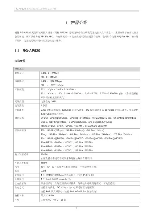
1 产品介绍锐捷RG-AP520无线局域网接入设备(简称AP520)是锐捷网络自主研发的无线接入点产品之一。
主要应用于室内比较复杂的环境,既可以作为瘦AP( Fit AP ),与有线无线一体化交换机/无线控制器合组网。
也可以作为胖AP( Fat AP ) 独立进行组网,为无线局域网用户提供无线接入服务。
1.1 RG-AP520规格参数硬件规格射频设计 2.4G:2×2MIMO5G:2×2MIMO传输协议 2.4G :802.11b/g/n5G :802.11a/n/ac工作频段802.11b/g/n :2.4G ~ 2.4835GHz802.11a/n/ac :5G:5.150~5.350GHz,5.47~5.725,5.725~5.850GHz (注:工作频段根据不同国家配置有所变化)天线类型内置全向3dBi空间流数2条流传输速率 2.4G提供最高提供300Mbps的接入速率,5G提供最高提供867Mbps的接入速率。
整机提供1.167Gbp的接入速率。
调制技术OFDM:BPSK@6/9Mbps,QPSK@12/18Mbps,16-QAM@24Mbps,64-QAM@48/54Mbps DSSS:DBPSK@1Mbps,DQPSK@2Mbps,and CCK@5.5/11MbpsMIMO-OFDM:BPSK,QPSK,16QAM 、64QAM and 256QAM接收灵敏度11b:-99dBm(1Mbps),-93dBm(5.5Mbps),-90dBm(11Mbps)11a/g:-93dBm(6Mbps),-85dBm(24Mbps),-82dBm(36Mbps),-77dBm(54Mbps)11n:-92dBm@MCS0,-74dBm@MCS7,-92dBm@MCS8,-73dBm@MCS1511ac HT20:-90dBm(MCS0), -65dBm(MCS8)11ac HT40:-85dBm(MCS0), -60dBm(MCS9)11ac HT80:-82dBm(MCS0), -58dBm(MCS9)最大发射功率27dBm实际发射功率遵照不同国家和地区法规而有所不同。

锐捷关于地铁无线的解决方案随着城市的发展,地铁已经成为人们出行的重要交通工具之一。
然而,在地铁隧道中提供稳定的无线网络信号一直是一个挑战。
为了解决这一问题,锐捷提出了一系列关于地铁无线的解决方案。
一、地铁隧道无线信号覆盖的难题1.1 地下环境复杂地铁隧道的环境复杂,存在大量的金属结构、混凝土墙壁等,这些会对无线信号的传输造成干扰。
1.2 人员密集地铁车厢内人员密集,会对无线信号的传输造成干扰,导致信号不稳定。
1.3 信号穿透性差地铁隧道深处信号穿透性差,会造成信号覆盖不足,影响用户体验。
二、锐捷的解决方案2.1 强大的信号覆盖能力锐捷提供的无线设备具有强大的信号覆盖能力,可以穿透复杂环境,保证在地铁隧道中提供稳定的无线网络信号。
2.2 技术创新锐捷不断进行技术创新,研发出适用于地铁隧道环境的无线设备,提高信号穿透性,解决人员密集情况下的信号干扰问题。
2.3 多频段支持锐捷的无线设备支持多频段,可以根据地铁隧道的特点选择最适合的频段,提高信号覆盖范围和稳定性。
三、智能管理系统3.1 远程监控锐捷提供智能管理系统,可以实现对地铁隧道无线设备的远程监控,及时发现并解决问题,保证网络的稳定运行。
3.2 自动优化智能管理系统可以根据实时数据对网络进行自动优化,提高网络性能,保证用户的上网体验。
3.3 数据分析智能管理系统还可以对网络数据进行分析,帮助地铁公司了解用户的上网习惯,为网络优化提供数据支持。
四、安全保障4.1 数据加密锐捷的无线设备支持数据加密功能,保障用户数据的安全性,防止信息泄露。
4.2 防火墙锐捷的无线设备内置防火墙功能,可以阻止恶意攻击,保障网络的安全稳定。
4.3 安全认证锐捷的无线设备支持多种安全认证方式,可以确保只有经过认证的用户才能接入网络,提高网络的安全性。
五、未来展望5.1 5G技术应用未来随着5G技术的广泛应用,地铁无线网络将迎来更大的发展空间,锐捷将继续进行技术创新,提供更先进的解决方案。
Ruijie Reyee Series Access Points Web-Based Configuration Guide_R61Copyright StatementRuijie Networks©2021Ruijie Networks reserves all copyrights of this document. Any reproduction, excerption, backup, modification, transmission, translation or commercial use of this document or any portion of this document, in any form or by any means, without the prior written consent of Ruijie Networks is prohibited.Exemption StatementThis document is provided “as is”. The contents of this document are subj ect to change without any notice. Please obtain the latest information through the Ruijie Networks website. Ruijie Networks endeavors to ensure content accuracy and will not shoulder any responsibility for losses and damages caused due to content omissions, inaccuracies or errors.PrefaceThank you for using our products.AudienceThis manual is intended for:●Network engineers●Technical support and servicing engineers●Network administratorsObtaining TechnicalAssistance●Ruijie Networks Website: https:///●Technical Support Website: https:///support ●Case Portal: https://●Community: https://●Technical Support Email: *****************************●Skype: *****************************Related DocumentsConventionsThis manual uses the following conventions:Configuration Guide Overview 1 OvervieweWeb is a Web-based network management system that manages or configures devices. You can access eWeb via browsers such as Google Chrome.Web-based management involves a Web server and a Web client. The Web server is integrated in a device, and is used to receive and process requests from the client, and return processing results to the client. The Web client usually refers to a browser, such as Google Chrome IE, or Firefox.1.1 ConventionsIn this document, texts in bold are names of buttons (for example, OK) or other graphical user interface (GUI) elements (for example, DHCP Security).2 Configuration Guide2.1 PreparationScenarioAs shown in the figure below, an administrator can access the device from a browser and configure the device through the eWeb management system.Figure 2-1-1 Data Exchange PrincipleDeliver or requestcommandsthrough AJAX.Administrator Return dataWebserviceDeviceDeployment↘Configuration Environment RequirementsClient requirements:●An administrator can log into the eWeb management system from a Web browser to manage devices. The client refersto a PC or some other mobile endpoints such as laptops or tablets.●Google Chrome, Firefox, IE10.0 and later versions, and some Chromium-based browsers (such as 360 ExtremeExplorer) are supported. Exceptions such as garble or format error may occur if an unsupported browser is used.●1024 x 768 or a higher resolution is recommended. If other resolutions are used, the page fonts and formats may not bealigned and the GUI is less artistic, or other exceptions may occur.●The client IP address is set in the same LAN network as the device IP address, such as 192.168.120.X. The subnetmask is 255.255.255.0. The default management address of the device is 192.168.120.1. Alternatively, you can set the IP assignment mode to Obtain an IP address automatically.Server requirements:●You can log into the eWeb management system through a LAN port or from Ruijie Cloud on an external network.●The device is enabled with Web service (enabled by default).The device is enabled with login authentication (enabled by default).To log into the eWeb management system, open the Google Chrome browser, and enter 192.168.120.1 into the address bar, and press Enter .Figure 2-1-2 Login PageEnter the password and click Login .2.2 Network SetupYou will enter the Network Setup page without login at initial setup.2.2.1 Discover DeviceThe page displays online device count and network status.You can add the device to My Network before configuring the network. If the device works in the standalone mode, this feature is not supported.Figure 2-2-1 Discover Device2.2.2 Add to My NetworkSelect the target device and click Add to My Network. If the target device is not configured yet, you can add the device directly without a password.Figure 2-2-2 Add Device to My Network2.2.3 Create Network & ConnectIf the device is configured for the first time, the network name, management password and SSID are required. If the device is already configured, the management password will not be displayed here. You can navigate to Network> Password to change the management password.If the device is detected disconnected to Ruijie Cloud, the Ruijie Cloud page will be embedded for you to bind your account after the device accesses the Internet successfully. If the device is already connected to Ruijie Cloud, the eWeb homepage will be displayed after this step.Figure 2-2-3 Create NetworkClick Create Network & Connect, and it takes about 60 seconds to deliver and activate settings. The following message will appear after Internet connection is set up.Figure 2-2-4 Connect to InternetIf the Internet connection failed, please follow the instruction in the prompt message.Figure 2-2-5 Failed Connection2.2.4 Cloud ServiceThe Network Setup module requires a Ruijie Cloud account. If you are a new user, please register an account first at the Ruijie Cloud website.Figure 2-2-6 Log In with Ruijie Cloud AccountIf the device works in the standalone mode, log in and the account will be bound with Ruijie Cloud automatically. If the device works in the self-organizing network mode, the following page will appear.Figure 2-2-7 Select TemplateFigure 2-2-8 Confirm Device StatusFigure 2-2-9 Enable ServicesClick Apply Config. The following page will appear after configuration is delivered successfully.Figure 2-2-10 CompleteAfter the above step, click Ruijie Cloud to configure the device on Ruijie Cloud. Then exit from Ruijie Cloud and enter the eWeb page again.Upon the configuration, check the network and wireless settings of each device for consistency.2.3 Work ModeThe eWeb menu varies with different work modes. The EG device works in the Router mode and the EAP device works in the AP mode by default. The work mode is displayed on the Route > Overview page.Figure 2-3-1 Device OverviewFigure 2-3-2 Work Mode2.3.1 Router ModeThe Router mode indicates NAT forwarding.The EG device in the Router mode of a router contains networking, network setup and routing features including VPN and behavior management.The AP in the Router mode contains networking, network setup and some radio features.2.3.2 AP ModeThe AP mode refers to fit AP mode. All WAN ports are enabled with DHCP by default. You can configure a WAN port with a static IP address or enable PPPoE manually.2.4 Self-Organizing NetworkClick the current work mode, and the following page will appear. You can enable or disable self-organizing network here.Figure 2-4-1 Self-Organizing Network2.4.1 EnableIf self-organizing network is enabled, the device in the network will be discovered and discover other devices. These devices will form a network and be synchronized with network settings.The menu on the left contains all network settings, including wireless management, switch management and system management.Figure 2-4-2 Enable Self-Organizing NetworkIf there is a wireless router enabled with self-organizing network in the network, the Router module will appear in the menu on the left. Click Router , and a horizontal menu will be displayed. Figure 2-4-3 Router Menu2.4.2DisableIf self-organizing network is disabled, the device will work in the standalone mode.After self-organizing network is disabled, a horizontal menu will be displayed vertically on the left. Figure 2-4-4 Disable Self-Organizing Network3 eWeb Configuration3.1 OverviewThe Overview page displays login device, wireless information and network status. Figure 3-1 Overview3.2 Basic WirelessThe APs module allows you to group, upgrade and delete APs.Figure 3-2-1 AP ListA. Group ManagementClick Expand, and all groups will be displayed on the left column. You can add, delete, edit and search groups. Up to 8 groups can be added.Figure 3-2-2 Group ManagementB. Advanced Search and List FilterClick Advanced Search, and you can search APs by SN, model, software version, MAC address and IP address.Click List Filter, and you can select columns to be displayed in the list.C. Batch ActionSelect the target devices and click Batch Action. The following actions are available:Figure 3-2-3 Batch ActionUpgrade Device: If there is a new version available, you can upgrade the devices in batches.Delete Device: You can delete the devices in batches.Change Group: You can move the devices from one group to another. The devices will be applied with the new group settings.3.2.1 ConfigurationFigure 3-2-4 ConfigurationSelect the target device and click Manage in the Action column, and the AP management page will be displayed.3.2.2 OverviewThe Overview page displays the information including memory usage, online clients, status, device details, wireless information and interface details.Figure 3-2-5 Overview3.2.3 Basics3.2.3.1 WANThe WAN module allows you to configure WAN settings. WAN settings support multiple lines, and you can configure a specific line as needed.Figure 3-2-6 WAN Settings3.2.3.2 LANThe LAN module contains LAN Settings, Port VLAN, DHCP Clients and Static IP Addresses. LAN SettingsThe LAN module allows you to set the IP address of the LAN port and DHCP status.Figure 3-2-7 LAN SettingsFigure 3-2-8 Add IP AddressIn the AP mode, the Port VLAN function is available on page for the AP supporting Port VLAN. Figure 3-2-9 Port VLAN↘Port VLANThe Port VLAN page displays VLAN information. This page is displayed only when the AP is enabled with port VLAN in the AP mode.Figure 3-2-10 Port VLAN↘DHCP ClientsThe DHCP Clients page displays DHCP clients. This page is displayed only in the router mode.Figure 3-2-11 DHCP ClientsClick Convert to Static IP in the Action column to convert a DHCP-assigned IP address to a static IP address. Alternatively, select DHCP-assigned IP addresses and click Batch Convert to convert more than one IP address.Static IP AddressesThe Static IP Addresses module allows you to add, delete and edit static IP addresses. This page is displayed only in the router mode.Figure 3-2-12 Static IP AddressesClick Add to add a static IP address manually. In the displayed dialog box, configure settings and click OK.Figure 3-2-13 Add Static IP Address3.2.3.3 PoEThe PoE page displays PoE status and power consumption. Figure 3-2-14 PoE3.2.4 Security3.2.4.1 ARP ListThe ARP List page displays ARP entries.Figure 3-2-15 ARP ListClick Add to add an IP-MAC binding. In the displayed dialog box, enter or select an IP address and a MAC address and click OK.Figure 3-2-16 Add IP-MAC Bindingdialog box, click OK. The message "Delete operation succeeded." is displayed.3.2.5 Advanced3.2.5.1 Local DNSThe Local DNS module allows you to configure a local DNS server.Figure 3-2-17 Local DNS3.2.5.2 PoE SettingsThe PoE Settings module allows you to configure the PoE mode.Figure 3-2-18 PoE Settings3.2.5.3 Other SettingsThe Other Settings module allows you to perform other settings, such as Enable RIP&RIPng, Enable Advanced and Disable ICMPv6 Error.Figure 3-2-19 Other Settings3.2.6 Diagnostics3.2.6.1 Network Check Figure 3-2-20 Network CheckClick Start, and click OK in the confirmation box. After the test finishes, the result will be displayed. Figure 3-2-21 ResultIf any problem occurs, the result will be displayed as follows:Figure 3-2-22 Issue & AdvicePlease fix the problem by taking the suggested action.3.2.6.2 AlarmsThe Alarms module allows you to view and manage alarms in the network.Figure 3-2-23 AlarmsClick Unfollow in the Action column to unfollow an alarm. In the confirmation box, click OK. Figure 3-2-24 Unfollow AlarmClick View Unfollowed Alarm, and you can view and follow the alarm again.Figure 3-3-25 Re-follow Alarm3.2.6.3 Network ToolsThe Network Tools module provides the following network tools to detect the network status: Ping, Traceroute, and DNS Lookup.Figure 3-2-26 Ping Test and ResultFigure 3-2-27 Traceroute Test and ResultFigure 3-2-28 DNS Lookup Test and Result3.2.6.4 Fault CollectionThe Fault Collection module allows you to collect faults by one click and download the fault information to the local device. Figure 3-2-29 Fault Collection3.2.7 System3.2.7.1 Session TimeoutThe Session Timeout module allows you to set the session timeout period.Figure 3-2-30 Session Timeout3.2.7.2 Backup & Import & ResetBackup & ImportThe Backup & Import module allows you to import a configuration file and apply the imported settings. It also allows exporting the configuration file to generate a backup.Figure 3-2-31 Backup & ImportRestoreThe Restore module allows you to restore the device to factory settings. Figure 3-2-32 RestorePlease exercise caution if you want to restore the factory settings. Figure 3-2-33 Confirm RestoreClick OK to restore all default values. This function is recommended when the network configuration is incorrect or the network environment is changed.3.2.7.3 UpgradeOnline UpgradeClick Upgrade Now. The device downloads the upgrade package from the network, and upgrades the current version. The upgrade operation retains configuration of the current device. Alternatively, you can select Download File to the local device and import the upgrade package on the Local Upgrade page.Figure 3-2-34 Online UpgradeFigure 3-2-35 Upgrade PromptLocal UpgradeClick Browse to select an upgrade package, and click Upload. After uploading and checking the package, the device displays the upgrade package information and a prompt asking for upgrade confirmation. Click OK to start the upgrade.Figure 3-2-36 Local Upgrade3.2.7.4 RebootThe Reboot module allows you to reboot the device immediately.Figure 3-2-37 RebootClick Reboot, and click OK in the confirmation box. The device is rebooted and you need to log into the eWeb management system again after the reboot. Do not refresh the page or close the browser during the reboot. After the device is successful ly rebooted and the eWeb service becomes available, you will be redirected to the login page of the eWeb management system.3.3 WiFiThe WiFi module allows you to configure WiFi settings for all devices.3.3.1 WiFi SettingsThe WiFi Settings module allows you to configure the primary WiFi.Figure 3-3-1 WiFi Settings3.3.2 Guest WiFiThe guest WiFi is disabled by default. You can enable guest WiFi on this page or homepage.AP isolation is enabled by default and cannot be edited.Set a schedule, and the guest WiFi will be enabled only during this period time. When the time expires, the guest WiFi will be disabled.Figure 3-3-2 Guest WiFiFigure 3-3-3 Enable Guest WiFi3.3.3 WiFi ListThe WiFi List displays all WiFi networks. The primary WiFi is also listed here and cannot be deleted.Figure 3-3-4 WiFi ListClick Add to add a WiFi network. In the displayed dialog box, configure settings and click OK. Figure 3-3-5 Add WiFiYou can click in the upper right corner to see description about each configuration item.3.3.4 Healthy ModeThe Healthy Mode module allows you to enable health mode and set a schedule. Figure 3-3-6 Healthy Mode3.4 Wireless ClientsThe Clients module displays the wireless clients.Figure 3-4-1 Wireless Client ListClick Advanced Search, and you can search clients by SN and MAC address. This is a fuzzy search. You can enter an incomplete MAC address or part of an SN. Figure 3-4-2 Advanced Search3.5 Blacklist/WhitelistThe Blacklist/Whitelist module allows you to configure wireless global or SSID-based client blacklist and whitelist. Blacklist and whitelist can achieve full match or prefix match (OUI).3.5.1 Global Blacklist/WhitelistFigure 3-5-1 Global Blacklist/WhitelistClick Add to add a blacklisted or whitelisted client. In the displayed dialog box, configure settings and click OK.。

如何使用锐捷认证无线上网
锐捷认证是一种常见的无线上网认证方式,许多学校、企事业单位和公共场所都采用这种认证方式来保障网络安全。
本文将详细介绍如何使用锐捷认证无线上网。
第一步:打开无线网络连接
首先,在电脑或移动设备中打开无线网络连接,找到可用的无线网络列表。
第二步:选择要连接的网络
在无线网络列表中,找到并选择要连接的锐捷认证无线网络。
通常,这些网络名称(SSID)前面会标有锐捷或学校/公司名称,并且可能需要输入账号和密码才能连接。
第三步:打开浏览器
第四步:输入账号和密码
第五步:点击认证按钮
输入完账号和密码后,点击认证按钮进行认证。
如果账号和密码正确且网络正常,您将会被成功认证并获得访问网络的权限。
第六步:备注或保存认证信息
一些锐捷认证系统可能会要求用户选择是否保存认证信息或备注个人设备名称。
这样,在下次连接同一个网络时,可以直接选择之前保存的认证信息,而无需重复输入账号和密码。
第七步:浏览网络
温馨提示:
1.锐捷认证无线上网通常会在一段时间后自动断开连接,因此,如果
网络中断,请重新进行认证并重新连接网络。
总结:
使用锐捷认证无线上网并不复杂,只需要按照以上步骤进行操作即可。
锐捷认证是一项重要的安全措施,可以保护无线网络免受未经授权的访问
和攻击。
RG-CT5000-G4系列云终端文档版本V1.0归档日期2023-04-24copyright © 2023 锐捷网络版权声明copyright © 2023 锐捷网络保留对本文档及本声明的一切权利。
未得到锐捷网络的书面许可,任何单位和个人不得以任何方式或形式对本文档的部分或全部内容进行复制、摘录、备份、修改、传播、翻译成其他语言、将其部分或全部用于商业用途。
、、和其他锐捷网络商标均为锐捷网络的商标。
本文档提及的其他所有商标或注册商标,由各自的所有人拥有。
免责声明您所购买的产品、服务或特性等应受商业合同和条款的约束,本文档中描述的部分或全部产品、服务或特性可能不在您的购买或使用范围之内。
除非合同另有约定,锐捷网络对本文档内容不做任何明示或默示的声明或保证。
由于产品版本升级或其他原因,本文档内容会不定期进行更新。
锐捷网络保留在没有任何通知或者提示的情况下对文档内容进行修改的权利。
本手册仅作为使用指导。
锐捷网络在编写本手册时已尽力保证其内容准确可靠,但并不确保手册内容完全没有错误或遗漏,本手册中的所有信息也不构成任何明示或暗示的担保。
前言读者对象本手册适合下列人员阅读●网络工程师●技术实施人员●网络管理员技术支持●锐捷网络官方网站:https://●锐捷网络官方网站服务与支持版块:https:///fw/●锐捷网络7*24h智能客服闪电兔:https://●锐捷网络7*24h技术服务热线:4008-111-000●锐捷网络售后服务工具——小锐云服:https:///special/fw/tool/xryf/●锐捷网络技术支持与反馈信箱:*********************.cn●锐捷网络文档支持与反馈信箱:**************.cn小锐云服APP 锐捷服务公众号本书约定1. 各类标志本书还采用各种醒目标志来表示在操作过程中应该特别注意的地方,这些标志的意义如下:危险表示重要安全操作指导。


锐捷网络股份有限公司了解更多产品信息,欢迎登陆,咨询电话:400-620-8818。
下一代网关RG-EG2000系列产品概述锐捷网络RG-EG2000系列网关是适用于多个行业的具有多合一功能特性的出口产品。
设备配以高性能的MIPS多核硬件体系架构,拥有高性能NAT、智能选路、集成AC、广域网加速、上网业务优化、智能流控、上网行为管理、内容审计、可视化IPSEC VPN、SSL VPN、防火墙、Web认证等多个功能。
凭借着丰富的功能,RG-EG系列能够极有效的优化用户网络,规范上网行为,全方位的加速关键业务开展,提高业务系统使用体验。
产品特性广域网优化——总部分支双边部署,加速分支访问总部业务RG-EG2000系列网关广域网优化技术适用于总部分支型网络,在总部和分支双边部署模式下,通过TCP协议优化、应用层协议优化、数据优化、低质量链路优化等关键性技术,实现分支访问总部业务系统的加速功能。
保证跨广域网访问业务系统能够达到局域网相接近的访问体验,提升业务系统的应用交付能力。
优化上网体验——“Mini Cache”,加速网页浏览、文件下载RG-EG2000系列网关还具备简单的缓存功能,能够对html、css、js、图片、flash等网页元素以及doc、tar、gz等大文件进行缓存。
减少网页浏览的响应时间、大文件下载缓存到本地,优化上网体验。
集成软AC——降低小型无线网络建网成本,配置简单易用RG-EG2000系列网关集成了无线AC控制器功能,最大可以支持32个AP的集中配置管理,对于小型的无线网络无需专门配备一台单独的AC设备,同时图形化的配置界面只需几步轻松完成配置,既省钱又易用。
适用于普教中小学无线校园网、商贸连锁、咖啡厅、小型企业无线办公网等场景。
RG-EG2000系列网关对内网用户的上网行为进行精细化管理。
屏蔽各种与工作无关的网站,营造良好工作氛围,提高工作效率;可对聊天工具、邮件、论坛、微博、搜索引擎等提供安全审计功能,保护内网信息安全。

技能大赛锐捷设备培训教程一、引言随着我国经济社会的快速发展,技能人才的需求日益增长,技能大赛作为选拔和培养技能人才的重要平台,越来越受到社会各界的关注。
锐捷网络设备作为我国网络设备行业的佼佼者,其产品在技能大赛中广泛应用。
为了帮助参赛选手更好地掌握锐捷网络设备的操作技能,提高参赛水平,本教程将详细介绍锐捷网络设备的基本操作和配置方法。
二、锐捷网络设备概述锐捷网络设备包括交换机、路由器、无线控制器等多种类型,广泛应用于企业、校园、数据中心等场景。
锐捷网络设备具有高性能、高可靠性和易管理等特点,能够满足不同场景的网络需求。
1.交换机:锐捷交换机分为接入层、汇聚层和核心层三个层次,支持千兆、万兆等速率,具备丰富的端口类型和扩展能力。
2.路由器:锐捷路由器采用高性能处理器,支持多种路由协议,具备强大的路由能力和安全防护功能。
3.无线控制器:锐捷无线控制器支持802.11ac、802.11n等无线标准,具备智能无线覆盖、用户接入控制等功能。
1.设备启动与关闭(1)启动设备:接通电源,设备将自动启动。
启动过程中,设备会进行自检,检查硬件设备是否正常。
(2)关闭设备:在设备正常运行状态下,通过命令行界面执行“shutdown”命令,设备将安全关闭。
2.设备登录与退出(1)登录设备:通过console口或telnet/ssh远程登录设备。
登录时需输入用户名和密码。
(2)退出设备:在命令行界面执行“quit”命令,退出当前视图;执行“logout”命令,退出设备登录。
3.命令行界面操作(1)查看命令:通过“display”命令查看设备运行状态、配置信息等。
(2)配置命令:通过“system-view”命令进入系统视图,进行设备配置。
(3)保存配置:执行“save”命令,将当前配置保存到设备中。
1.交换机配置(1)基本配置:配置设备名称、管理IP地质、接口速率等。
(2)VLAN配置:创建VLAN,并将接口加入VLAN。
802.11ac/802.11ac Wave 2 Superior Wireless PerformanceBuilt-in Smart Antenna & Lightning Arrester Outstanding EnvironmentalAdaptability (IP67, -40-55°C)RUIJIE NETWORKS COMPANY LIMITED RG-AP630Ruijie RG-AP630 Series is a family of top-class 802.11ac wireless accesspoints for next-gen high-speed wireless network applications. The RG-AP630 Series consists of 3 models RG-AP630(IDA2), RG-AP630(IODA)and RG-AP630(CD).The RG-AP630 (IODA) offers access rates up to 1.75 Gbps, the RG-AP630(IDA2) supports 2.533Gbps access rate and the RG-AP630(CD)supports 1.167Gbps access rate. The RG-AP630 Series takes full careof security, RF control, mobile access, QoS, seamless roaming and otherWi-Fi aspects. Teaming up with Ruijie RG-WS Wireless Controller Series/HIGHLIGHTSCloud AC, the APs offer Wi-Fi user data forwarding, advanced security and access control with ease.The industrial-class AP enclosure (IP67 rated) can withstand extreme outdoor conditions and hence simplify device installation and maintenance. The RG-AP630 (IDA2) is built-in with directional antenna while the RG-AP630(IODA) offers internal omnidirectional antenna. An extensive collection of external antennas is also available to overcome various deployment challenges. Both AP models support automatic switching between the external and internal antennas. RG-AP630 (CD), equipped with built-in directional antenna, can achieve the outdoor Wi-Fi coverage under extreme outdoor conditions in vast majority of the scenarios. Multi-hop Outdoor AP Series thereby offers unparalleled productivity in a wide variety of outdoor networking solutions.RG-AP630(IDA2)/(IODA)Outdoor Antennas (from left to right):RG-ANTx3-2400D, RG-ANTx3-5800D & RG-ANTx3-2400&5800(O) RG-AP630(CD)PRODUCT FEATURESHigh Performance & Reliability802.11ac Superior Wireless PerformanceThe RG-AP630 Series supports **************and 802.11ac@5GHz, with RG-AP630 (IODA) offering access rates of up to 1.75Gbps, RG-AP630(IDA2) up to 2.533Gbps and RG-630(CD) up to 1.167Gbps. The outstanding wireless performance greatly optimizes wireless user experience, increases the number of concurrent users and enhances signal coverage.Built-in Smart Antenna of AP630(IDA2)/ (IODA) Equipped with built-in antenna, the RG-AP630 Series can achieve a real-time antenna beam switching based on the location of access devices, ensuring optimal wireless experience. The APs also support switching of internal and external antennasThe Industry’s Most Flexible Gigabit UplinkThe RG-AP630 Series offers a 10/100/1000Base-T Ethernet uplink port that rids the LAN port of being the wireless access bottleneck, and a 1000M SFP combo port that adapts to wired networking structure under different user scenarios. The SFP Base-X port takes up the data transmission workload for optimal network deployment. Easy-to-use Mount-KitAn adjustable mount-kit is available by default for painless deployment optimization. The APs can be easily adjusted -60° to 60° horizontally and -60° to 90° vertically to adapt to variousscenarios.56Hardware HighlightsInterfaces1.Console Port2.10/100/1000Mbps ETH2 IN Port3.10/100/1000Mbps ETH1/PoE IN Port4.SFP Port (Combo with ETH1)5. 3 2.4GHz N-K Type RF Connectors6. 3 5GHz N-K Type RF ConnectorsAll-in-one Package for Painless DeploymentThe RG-AP630 Outdoor AP Series offers you a one-stopinstallation package. Everything youneed is included, fromexternal antennas to lightning arresters and coaxial cables, foreffortless outdoor deployment.RG-AP630(IODA)Built-in Directional and Omnidirectional Antennas of AP630Adjustable Mount-kit of AP630All-in-one Installation PackageFlexible WDS ModeThe APs implement WDS (Wireless Distribution System) tosupport interconnection of multiple APs or wireless bridgingunder 5 hops. Wireless bridging can be achieved even for along distance. The outdoor APs also support point-to-multipointThe features get over the outdoor deployment problems tosupport large-scale and remote high-speed wireless coverage.Intelligent Device RecognitionThe APs support intelligent recognition of end devices runningmainstream operating systems such as iOS and Android.Industry-leading Local Forwarding TechnologyEmploying an industry-leading local forwarding technology, theComprehensive Security PoliciesUser Data EncryptionThe outdoor APs offer protected Wi-Fi access with the support of cutting-edge encryption technologies such as WEP , TKIP and AES, guaranteeing the data transmission security of the wireless network.Virtual AP TechnologyWith the virtual AP technology, the AP can offer up to 16 ESSIDs (per radio) and 16 802.1Q VLANs. The network administrator can separately encrypt and isolate subnets or VLANs that have the same SSID. A separate authentication mode and encryptionDeploying with the Ruijie RG-WS Wireless Controller Series, outdoor APs. The APs also control if the data will be forwarded via the wireless controller. The local forwarding technology can forward large-scale, delay-sensitive, and real-time transmissionthe 802.11ac network.Seamless Roaming ExperienceThe APs team up with the RG-WS Wireless Controllers in perfect harmony, allowing wireless users to roam seamlessly on Layer 2 and Layer 3 networks without data interruption.Abundant QoS PoliciesThe AP supports a wide range of QoS policies. For example, it provides WLAN/AP/STA-based bandwidth limitation modes that prioritize key services over others.Outstanding Environmental AdaptabilityThe outdoor APs offer an IP67-rated enclosure that fulfills waterproof, dustproof, moisture-proof and flame retardant requirements to withstand harsh environments such as wind erosion, rain and high humidity. The features greatly lengthen the equipment life span and effectively reduce the maintenance cost.Wide Operating Temperature RangeAll the AP components and enclosures can withstand a wide temperature range from -40°C to 55°C without any influence on the stability and life span. The design ensures the metal in heater module guarantees stable operation under freezing conditions.Standard CAPWAP EncryptionCAPWAP (Control and Provisioning of Wireless Access Points) enables communication between RG-WS Wireless Controllers and the outdoor APs. The standard ensures secure data transmission.RF SecurityIn collaboration with Ruijie’s RG-SNC Smart Network Commander and RG-WS Wireless Controllers, the APs enable the RF probe scanning mechanism to detect unauthorized access points or other RF interference sources. Once detected, the APs will alert network administrator to monitor potential threats and usage status in the wireless environment.User Access ControlThe APs support a wide range of authentication methods such as Web, 802.1x, MAC address and local authentication. The APs also support Ruijie’s advanced Security Management Platform (SMP) BYOD Solution which complies with a standard access control system. The system has a set of control policies in terms of user access, authorization, host compliance check, network behavior monitoring, network attack defense, etc. All these control features ensure that users are authenticated before accessing the network services securely.Wireless ProtectionTogether with Ruijie’s RG-SNC Smart Network Commander and RG-WS Wireless Controllers, the APs provide a powerful range of wireless security features such as Wireless Intrusion Detection System (WIDS), RF Interference Location, Rogue AP a truly secure and reliable wireless network.Wireless IPv6 AccessComprehensive IPv6 features are available to enable IPv6 forwarding on a wireless network. Both IPv4 and IPv6 users can connect to the ACs over tunnels, enabling IPv6 applications to be borne on the wireless network.Flexible Authentication ModesThe APs support convenient Protected Extensible Authentication Protocol (PEAP), SMS Authentication, and QR Code Authentication.The PEAP Authentication allows users to perform password authentication for once only. That means users are only required If the SMS authentication is adopted, users first sign in with their mobile phone numbers and then receive an SMS with loginTECHNICAL SPECIFICATIONS username and password for network access.QR code authentication is another wireless security highlight. After accessing a wireless network, users will obtain a QR code on their end devices and simply ask any authorized staff’s to scan it for network access.Flexible Device Management ModeFlexible Switching Between the FAT & FIT Modesaccording to the networking requirements of different industries. When there are few APs, users can adopt the FAT mode for easy independent network establishment. For large-scale networks, the APs can operate in FIT mode which allows centralized management of all the APs and other aspects such as security, traffic management, QoS and IP management when deployed with the RG-WS Wireless Controllers. Smooth transition from one to another, the APs fully protect user investment.Under the FIT mode, no AP configuration is required before deployment. Also, no manual configuration is necessary forOutdoor APson-site installation, maintenance or replacement. Auto-feature can greatly reduce workload and investment costs.Comprehensive Remote ManagementThe RG-WS Wireless Controllers or Cloud AC can remotely and centrally manage all AP operations such as channel, power ranking, SSID configuration, security configuration, VLAN division and so on. The feature enhances security andPoE Port For Easy Deployment & MaintenanceThe RG-AP630(IDA2)/(IODA) support the 802.3at PoE standard while RG-AP630(CD) supports the 802.3af PoE standard. By connecting to a HPoE switch through the AP Ethernet port, the outdoor APs can gain power and support data transmission via cables. The network administrator canmaximizes the cost savings.Outdoor AntennasORDERING INFORMATION。
Ruijie Reyee RG-RAP2260(E)Access PointDocument Version: V1.1 Date: 2023.03.02CopyrightCopyright © 2023 Ruijie NetworksAll rights are reserved in this document and this statement.Without the prior written consent of Ruijie Networks, any organization or individual shall not reproduce, extract, back up, modify, or propagate the content of this document in any manner or in any form, or translate it into other languages or use some or all parts of the document for commercial purposes., and other Ruijie networks logos are trademarks of Ruijie Networks.All other trademarks or registered trademarks mentioned in this document are owned by their respective owners. DisclaimerThe products, services, or features you purchase are subject to commercial contracts and terms, and some or all of the products, services, or features described in this document may not be available for you to purchase or use.Except for the agreement in the contract, Ruijie Networks makes no explicit or implicit statements or warranties with respect to the content of this document.The content of this document will be updated from time to time due to product version upgrades or other reasons, Ruijie Networks reserves the right to modify the content of the document without any notice or prompt.This manual is designed merely as a user guide. Ruijie Networks has tried its best to ensure the accuracy and reliability of the content when compiling this manual, but it does not guarantee that the content of the manual is completely free of errors or omissions, and all the information in this manual does not constitute any explicit or implicit warranties.PrefaceIntended AudienceThis document is intended for:●Network engineers●Technical support and servicing engineers●Network administratorsTechnical Support●The official website of Ruijie Reyee: https:///products/reyee●Technical Support Website: https:///support●Case Portal: https://●Community: https://●Technical Support Email: *****************************Conventions1. SignsThis document also uses signs to indicate some important points during the operation. The meanings of these signs are as follows:CautionAn alert that calls attention to safety instruction that if not understood or followed can result in personal injury.WarningAn alert that calls attention to important rules and information that if not understood or followed can result indata loss or equipment damage.NoteAn alert that calls attention to essential information that if not understood or followed can result in functionfailure or performance degradation.InstructionAn alert that contains additional or supplementary information that if not understood or followed will not lead to serious consequences.SpecificationAn alert that contains a description of product or version support.2. NoteThis manual provides installation steps, troubleshooting, technical specifications, and usage guidelines forcables and connectors. It is intended for users who want to understand the above and have extensiveexperience in network deployment and management, and assume that users are familiar with related terms and concepts.ContentsPreface (I)1Product Overview (1)1.1Technical Specifications (1)1.2Product Image (2)1.3LED Indicator and Button (2)1.4Power Sources (3)1.5Cooling Solution (3)2Preparing for Installation (4)2.1Installation (4)2.2Movement (4)2.3EMI (4)2.4Ventilation (5)2.5Temperature and Humidity (5)2.6Cleanness (5)2.7Power Supply (6)2.8Installation Tools (6)2.9Unpacking the Access Point (7)3Installing the Access Point (8)3.1Installation Flowchart (8)3.2Before You Begin (8)3.3Precautions (8)3.4Installing the Access Point (9)3.5Removing the Access Point (10)3.6Connecting Cables (10)3.7Bundling Cables (10)3.8Checking after Installation (11)4System Debugging (12)4.1Setting up a Debugging Environment (12)4.2Powering up the AP (12)4.2.1Checking before power-up (12)4.2.2Checking after power-up (recommended) (12)5Monitoring and Maintenance (13)5.1Monitoring (13)5.1.1Hardware Maintenance (13)6Troubleshooting (14)6.1Troubleshooting Flowchart (14)6.2Troubleshooting (14)Appendix A Connectors and Media (15)·1 Product OverviewFeaturing leading 802.11a/b/g/n/ac/ax and MU-MIMO, Ruijie RG-RAP2260(E) supports 4 spatial streams and delivers upto 800 Mbps at 2.4 GHz and 2400 Mbps at 5 GHz. The overall dual-band performance speeds up to 3200 Mbps perdevice, totally eliminating Gigabit wireless bottlenecks. RG-RAP2260(E) adopts either local power supply or PoE powersupply, and provides two Ethernet ports, making it possible connect a camera or switch device to adapt to challenges in awide variety of deployment scenarios.1.1 Technical SpecificationsTable 1-1 RG-RAP2260(E) Technical SpecificationsModel RG-RAP2260(E)RF Four-stream and dual-bandTransmissionProtocolSupport concurrent 802.11ax, 802.11ac wave2/wave1, 802.11a/b/g/nOperating Bands 802.11b/g/n: 2.4 GHz to 2.4835 GHz802.11a/n/ac/ax: 5.150 GHz to 5.250 GHz, 5.250 GHz to 5.350 GHz, 5.470 GHz to 5.725 GHz, 5.725 GHz to 5.850 GHz (Country-specific)Antenna Array antenna (2.4 GHz: 3dBi, 5 GHz: 3dBi)Spatial Streams 2.4 GHz: 4 x 4 MIMO5 GHz: 4 x 4 MIMOMax Throughput 2.4 GHz: up to 800 Mbps5 GHz: up to 2400 MbpsUp to 3200 Mbps per APModulation OFDM: BPSK@6/9Mbps, QPSK@12/18Mbps, 16QAM@24Mbps, 64QAM@48/54Mbps DSSS:DBPSK@1Mbps,DQPSK@2Mbps,**********/11MbpsMIMO-OFDM: BPSK, QPSK, 16QAM , 64QAM, 256QAM and1024QAMOFDMAReceive Sensitivity 11b: -91dBm(1Mbps), -90dBm(5Mbps), -87dBm(11Mbps)11a/g: -89dBm(6Mbps), -82dBm(24Mbps), -78dBm(36Mbps), -72dBm(54Mbps) 11n: -85dBm(MCS0), -67dBm(MCS7)11ac: 20MHz: -85dBm(MCS0), -60dBm(MCS9)11ac: 40MHz: -82dBm(MCS0), -57dBm(MCS9)11ac: 80MHz: -79dBm(MCS0), -53dBm(MCS9)11ax: 80MHz: -79dBm(MCS0), -53dBm(MCS9),-52dBm(MCS11)Transmit Power ≤100mw(20dBm) (adjustable)Transmit PowerAdjustment1 dBmDimensions(W x D x H)220 mm x 220 mm x 35 mm (8.7 in. x 8.7 in. x 1.4 in.) (excluding brackets)Weight ≤1.05 kg (excluding brackets)Service Ports One 10/100/1000BASE-T Ethernet uplink port, one 10/100/1000/2500BASE-T Ethernet uplink·port,LAN1/2.5G/PoE port is PoE+-capableManagement Ports N/ALED 1 LED (green)Power Supply Adapter: DC 12 V/2.5 A (optional)PoE: IEEE 802.3at-compliant (PoE+).Power Consumption < 25.4WTemperature Operating: 0°C to 40°C (32°F to 104°F) Storage: –40°C to 70°C (–40°F to 158°F)Humidity Operating: 5% to 95% RH (non-condensing) Storage: 5% to 95% RH (non-condensing)Installation Ceiling/wall mountCertification CEMTBF > 400,000 HWeight refers to the weight of host.1.2 Product ImageThe AP provides two Ethernet ports (LAN1/2.5G/PoE port is PoE+-capable), and one 12V DC power port for an external power supply.Figure 1-1 Appearance of RG-RAP2260(E)1.3 LED Indicator and ButtonLED Indicatorand ButtonState Frequency Meaning·LED IndicatorOff N/A The AP is NOT receiving power.Blinking0.5HzNormal operation, but there is an alarm. Fast blinking10HzPossible cases:1. Restoring the factory default settings2. Upgrading the firmware3. Restoring the image file4. Initializing the deviceSolid greenN/ANormal operation. Reset ButtonPress for less than 2 seconds Restart the device.Press for more than 5 secondsRestore the factory settings.1.4 Power SourcesThe AP can be powered either with a power adapter or through Power over Ethernet (PoE).The power adapter is customer-supplied.To use a PoE device, make sure that it supports the IEEE 802.3at standard.1.5 Cooling SolutionThe AP features a fanless design.Leave sufficient space surrounding the AP when installing the AP to permit proper airflow for ventilation.·2 Preparing for InstallationTo prevent device damage and physical injury, please read the safety recommendations carefully as described inthis chapter.Recommendations do not cover all possible hazardous situations.2.1 InstallationThe AP must be installed indoors. To ensure normal operation, the installation site must meet the following requirements.●Install the AP in a well-ventilated environment. If it is installed in a closed room, make sure there is a good coolingsystem.●Make sure the site is sturdy enough to support the AP and its accessories.●Make sure the site has enough space for installing the AP and leave sufficient room around the AP for ventilation.●Do not expose the AP to high temperature, dust, or harmful gases.●Do not install the AP in an area prone to fire or explosions.●Keep the AP away from EMI sources such as large radar stations, radio stations, and substations.●Do not subject the AP to unstable voltage, vibration, and noises.●Keep the AP at least 500 meters away from the ocean and do not face it towards the sea breeze.●The installation site should be free from water including possible flooding, seepage, dripping, or condensation.●The installation site should be selected according to network planning and communications equipment features, andconsiderations such as climate, hydrology, geology, earthquake, electrical power, and transportation.Please follow the correct method described in the installation guide to install and remove the device.2.2 Movement●Avoid frequently moving the device.●Turn off all power supplies and unplug all power cables before you remove the device.2.3 EMI●Please observe local regulations and specifications when performing electrical operations. Relevant operators mustbe qualified.●Carefully check for any potential hazards in the working area such as damp/wet ground or floors.●Find the location of the emergency power supply switch in the room before installation. Cut off the power supply firstin case of an accident.●Be sure to make a careful check before shutting down the power supply.●Do not place the device in a damp/wet location. Do not let any liquid enter the chassis.·●Keep the AP far away from grounding or lightning protection devices for power equipment.●Keep the AP away from radio stations, radar stations, high-frequency high-current devices, and microwave ovens.Any nonstandard and inaccurate electrical operation can cause an accident such as fire or electric shock, thuscausing severe even fatal damages to humans and devices.Direct or indirect contact with a wet object (or your finger) on the high voltage and power line can be fatal.2.4 VentilationFor proper ventilation, leave sufficient space around the AP.2.5 Temperature and HumidityTo ensure the normal operation and equipment service life, maintain appropriate temperature and humidity levels in theequipment room. See Table 2-1. Improper room temperature and humidity can cause damage to the device.●High relative humidity may affect insulation materials, resulting in poor insulation and even electrical leakage.Sometimes it may lead to changes in the mechanical properties of materials and corrosion of metal parts.●Low relative humidity can dry and shrink insulation sheets and cause static electricity that can damage the circuitry.●High temperatures greatly reduce device reliability and shorten service life.Table 2-1 Required Temperature and Humidity for the RG-RAP2260(E)Temperature Relative Humidity0ºC to 40ºC (32°F to 104°F) 5% to 95%2.6 CleannessDust poses a serious threat to device operation. Dust on the surface of the device can be absorbed onto metal contactpoints by static electricity causing poor contact. Electrostatic absorption of dust occurs more easily when the relativehumidity is low, and might shorten the equipment service life and cause communication failures. Table 2-2 shows themaximum concentration and diameter of dust allowed in the equipment room.Table 2-2Maximum diameter (μm)0.5 1 3 5Maximum concentration1.4×1077×1052.4×105 1.3×10⁵(Particles/m3)The amount of salt, acids and sulfides in the air are also strictly limited for the equipment room. These substances canaccelerate metal corrosion and aging of some parts. Table 2-3 describes the limits of some hazardous gases such as SO2,H2S, NO2 and Cl2 in the equipment room.Table 2-3·Gas Average (mg/m3) Maximum (mg/m3)SO20.2 1.5H2S 0.006 0.03NO20.04 0.15NH30.05 0.15Cl20.01 0.32.7 Power Supply●DC power adapter:Input voltage: 12VRated current: 2.5A●PoE+ injector: IEEE 802.3at compliantTechnical Specifications of the DC ConnectorInner DiameterOuter DiameterInsertionDepthConductorImpedanceVoltage-enduranceImpedanceVoltage-endurance(Insulator andConductor)Polarity 2.10+/-0.05mm 5.50+/-0.05mm 9mm 5Ω100MΩ1000VInner pole:positiveOuter pole:negativeThe DC input power should be greater than the power actually consumed by the system.Use DC power adapters with specifications recommended by Ruijie.Please use Ruijie certified PoE injectors.Warning:802.3af or non-standard PoE adapter may cause unknown issues. Please use Ruijie PoE+ switch or 802.3at PoE adapter as power supplier2.8 Installation ToolsCommon Tools Phillips (crosshead) screwdriver, copper and fiber cables, bolts, diagonal pliers, cable ties Special Tools Wire stripper, crimping pliers, RJ-45 crimping pliers, punch down toolMeter Multimeter, bit error rate tester (BERT)The tools listed above are customer supplied.·2.9 Unpacking the Access PointPackage ContentsItemsVerify that all parts are installed and debugged.ScrewsMounting bracketsProduct quick installation guide Packing listThe above listed items are for general situations, and contents may vary in the actual shipment. The purchasingorder shall prevail in any case. Please check each item carefully according to the packing list or purchasing order. If any item is damaged or missing, notify your sales representative.·3 Installing the Access PointThe RG-RAP2260(E) series must be fixed and installed indoors.Before installing the AP, make sure you have carefully read the requirements described in Chapter 2.3.1 Installation Flowchart3.2 Before You BeginBefore installing the AP, verify that:●The installation site provides sufficient ventilation for the AP.●The installation site meets temperature and humidity requirements.●The installation site is equipped with a proper power supply.●Network cables are in place.●The installation site meets all described requirements.●The custom AP meets customer requirements.3.3 PrecautionsTo avoid damage to the AP, observe the following safety precautions:●Do not power on the device during installation.●Install the device in a well-ventilated location.●Do not subject the device to high temperatures.●Keep away from high voltage cables.●Install the device indoors.●Do not expose the device in a thunderstorm or strong electric field.●Keep the device clean and dust-free.●Disconnect the device before cleaning it.●Do not wipe the device with a damp cloth.·●Do not wash the device with liquid.●Do not open the enclosure when the AP is working.●Fasten the device tightly.3.4 Installing the Access PointPlease install the AP in the method with a larger antenna coverage area.The antenna coverage area of ceiling-mounting is larger than that of wall-mounting indoors. Please select the formermethod.The installation process below is just for reference. The actual product prevails.●Ceiling Mount1. Attach the mounting bracket on the ceiling or wall, as shown in Figure 3-1.Figure 3-1 Attaching the Mounting Bracket on the Ceiling/Wall2. Connect the Ethernet cable to the LAN1 port. See Figure 3-2.Figure 3-2 Connecting the Ethernet Cable to the LAN1 Port3. Align the square feet on the rear of the AP over the mounting holes on the bracket. Slide the AP into the holes until itclicks into place, as shown in Figure 3-3.Figure 3-3 Fastening the AP·Install the Ethernet cables before mounting the AP on the bracket.The AP can be installed in any of four directions on the mounting bracket depending on how you route the Ethernetcable.The square feet should fit easily into the mounting slots. Do not forcibly push the AP into the slots.After installation, verify that the AP is securely fastened.3.5 Removing the Access PointHold the AP in your hands and push it upward and away from the bracket in the arrow direction, as shown in Figure 3-1.3.6 Connecting CablesConnect the UTP/STP to the LAN1 port on the AP. See Appendix A for the supported wiring for twisted pairs.Avoid bending the cable in a small radius close to the connector.Ruijie recommends that you do not use Ethernet cables with protective sleeves as they could make installation ofEthernet cables more difficult.3.7 Bundling CablesPrecautions●Make sure the cable bundles are neat and orderly.●Bend twisted pairs naturally or in a large radius close to the connector.●Do not over tighten a cable bundle as it may reduce cable life and performance.Bundling Steps1. Bundle the drop UTP/STP cables and route them to the LAN1/2.5G/PoE port.2. Attach the cables in the cable tray of the rack.3. Extend the cables under the AP and run in a straight line.·3.8 Checking after InstallationChecking the Cabinet●Make sure the external power supply matches the patch panel specifications for the cabinet.●After installation, make sure that the front and rear cabinet doors easily close.●Make sure the cabinet is stable and level.●Make sure the device and all cables are securely fastened in the rack.Checking Cable Connection●Make sure the UTP/STP cable matches the interface type.●Make sure cables are properly bundled.Checking the Power Supply●Make sure all power cables are properly connected and safe.●Make sure the AP is operational after powering on.4 System Debugging4.1 Setting up a Debugging EnvironmentUse a power adapter or PoE to power the AP.Setting up the Environment●Verify that the AP is properly connected to the power source.●Connect the AP to a wireless controller through a twisted pair cable.●When the AP is connected to a PC for debugging, verify that the PC and PoE switch are properly grounded.4.2 Powering up the AP4.2.1 Checking before power-up●Verify that the power supply is properly connected.●Verify that the input voltage matches the specification of the AP.4.2.2 Checking after power-up (recommended)After powering up, it is recommended that you check the following to ensure normal operation of the AP.●Check if any message is displayed on the Web-based configuration interface for the wireless controller.●Check if the LED works normally.5 Monitoring and Maintenance5.1 MonitoringLEDYou can observe the LED to monitor the AP in operation.5.1.1 Hardware MaintenanceIf the hardware is faulty, please contact our Technical Assistance Center (TAC) for help.6 Troubleshooting6.1 Troubleshooting Flowchart6.2 TroubleshootingLED does not light up after the AP is powered on1. If you use PoE power supply, verify that the power source is IEEE 802.11at compliant; then verify that the cable is properly connected.2. If you use a power adapter, verify that the power adapter is connected to an active power outlet; then verify that the power adapter works properly.Ethernet port is not working after the Ethernet port is connectedVerify that the device at the other end of the Ethernet cable is working properly. And then verify that the Ethernet cable is capable of providing the required data rate and is properly connected.Wireless client cannot find the AP1. First, follow the two steps above.2. Verify that the AP is correctly configured.3. Adjust the angle of the antennas.4. Move the client device to adjust the distance between the client and the AP.·Hardware Installation and Reference Guide Appendix A Connectors and MediaAppendix A Connectors and Media1000BASE-T/100BASE-TX/10BASE-TThe 1000BASE-T/100BASE-TX/10BASE-T is a 10/100/1000 Mbps auto-negotiation port that supports auto MDI/MDIX. Compliant with IEEE 802.3ab, 1000BASE-T requires Category 5e 100-ohm UTP or STP (STP is recommended) with a maximum distance of 100 meters (328 feet).1000BASE-T requires all four pairs of wires be connected for data transmission, as shown in Figure A-1.Figure A-1 1000BASE-T Connection10BASE-T uses Category 3, 4, 5 100-ohm UTP/STP and 1000BASE-T uses Category 5 100-ohm UTP/STP for connections. Both support a maximum length of 100 meters. Table A-1 shows 100BASE-TX/10BASE-T pin assignments. Table A-1 100BASE-TX/10BASE-T Pin AssignmentsFigure A-2 shows wiring of straight-through and crossover cables for 100BASE-TX/10BASE-T.Figure A-2 100BASE-TX/10BASE-T Connection。
RG-WS5302无线控制器产品介绍福建星网锐捷网络有限公司目录1产品图片 (1)2产品概述 (2)3产品特性 (3)4技术参数 ......................................................................................................................... 错误!未定义书签。
5典型应用 .. (7)6订购信息 (11)1 产品图片图1-1RG-WS53022 产品概述RG-WS5302无线控制器是锐捷网络推出的面向下一代高速无线网络的无线控制器产品,专为中小型无线网络设计,可突破三层网络保持与AP的通信,部署在任何2层或3层网络结构中,无需改动任何网络架构和硬件设备,从而提供无缝的安全无线网络控制。
RG-WS5302提供了2个千兆光电复用端口,为高效的数据转发提供了硬件支持。
RG-WS5302起始支持32个无线接入点的管理,通过license 的升级,最大可支持128个无线接入点的管理。
RG-WS5302可针对无线网络实施强大的集中式可视化的管理和控制,显著简化原本实施困难、部署复杂的无线网络。
通过与锐捷网络有线无线统一集中管理平台RG-SNC以及无线接入点的配合,灵活地控制无线接入点的配置,优化射频覆盖效果和性能,同时还可实现集群化管理,将网络中的设备部署工作量将至最低。
RG-WS5302产品采用增强的安全和集群技术,通过基于身份的组网来提供网络服务。
集群中的多台无线控制器可共享用户数据库,实现无线用户在跨越整个网络不同区域的过程中无缝的漫游,彻底满足移动漫游中的安全性和会话完整性,充分满足Wi-Fi语音通信的数据交互和语音流畅。
3 产品特性高智能的无线体验终端智能识别RG-WS5302内置Portal服务器,能根据终端特点,智能识别终端类型,自适应弹出不同大小、页面格局的Portal认证页面。
锐捷网络股份有限公司了解更多产品信息,欢迎登陆 ,咨询电话:400-100-0078。
RG-RAC64高性能无线控制器产品简介RG-RAC64高性能无线控制器是锐捷睿易推出的面向下一代高速无线网络的无线控制器产品。
可突破三层网络保持与AP的通信,部署在任何2层或3层网络结构中,无需改动任何网络架构和硬件设备,从而提供无缝的安全无线网络控制。
RG-RAC64起始支持32个无线接入点的管理,通过license 的升级,最大可支持64个AP的管理。
RG-RAC64产品采用增强的安全和集群技术,通过基于身份的组网来提供网络服务。
集群中的多台无线控制器可共享用户数据库,实现无线用户在跨越整个网络不同区域的过程中无缝的漫游,彻底满足移动漫游中的安全性和会话完整性,充分满足Wi-Fi语音通信的数据交互和语音流畅。
产品特性与价值高智能的无线体验■终端智能识别RG-RAC64内置Portal服务器,能根据终端特点,智能识别终端类型,自适应弹出不同大小、页面格局的Portal认证页面。
终端智能识别技术免去了用户多次拖动,调整屏幕的操作,为用户提供更加智能的无线体验,并且全面支持苹果iOS、安卓和windows等主流智能终端操作系统。
■终端公平访问RG-RAC64协同锐捷无线接入点为802.11g、802.11n、802.11ac等不同类型的终端提供相同的访问时间,极大的解决了因终端无线网卡老旧或终端离AP较远而导致用户无线上网延时大、速度慢、AP整机性能低下的问题,有效的提升了低速终端的性能,保证用户无论使用何种类型的终端,都将在相同的位置上获得同样良好的无线上网体验。
■智能负载均衡在高密度无线用户的情况下,RG-RAC64智能实时的根据每个关联的AP上的用户数及数据流量调整分配到不同的AP上提供接入服务,平衡接入负载压力,提高用户的平均带宽和QoS,提高连接的高可用性。
锐捷无线不仅能实现基于用户、流量的智能负载均衡,而且还能实现基于频段的负载均衡。
RG-AP180-L-A 无线接入点文档版本V1.4归档日期2023-02-02copyright © 2023 锐捷网络版权声明copyright © 2023 锐捷网络保留对本文档及本声明的一切权利。
未得到锐捷网络的书面许可,任何单位和个人不得以任何方式或形式对本文档的部分或全部内容进行复制、摘录、备份、修改、传播、翻译成其他语言、将其部分或全部用于商业用途。
、和其他锐捷网络商标均为锐捷网络的商标。
本文档提及的其他所有商标或注册商标,由各自的所有人拥有。
免责声明您所购买的产品、服务或特性等应受商业合同和条款的约束,本文档中描述的部分或全部产品、服务或特性可能不在您的购买或使用范围之内。
除非合同另有约定,锐捷网络对本文档内容不做任何明示或默示的声明或保证。
由于产品版本升级或其他原因,本文档内容会不定期进行更新。
锐捷网络保留在没有任何通知或者提示的情况下对文档内容进行修改的权利。
本手册仅作为使用指导。
锐捷网络在编写本手册时已尽力保证其内容准确可靠,但并不确保手册内容完全没有错误或遗漏,本手册中的所有信息也不构成任何明示或暗示的担保。
前言读者对象本手册适合下列人员阅读●网络工程师●技术实施人员●网络管理员技术支持●锐捷网络官方网站:●锐捷网络官方网站服务与支持版块:/fw/●锐捷网络7*24h智能客服闪电兔:●锐捷网络7*24h技术服务热线:4008-111-000●锐捷网络售后服务工具——小锐云服:/special/fw/tool/xryf/●锐捷网络技术支持与反馈信箱:*********************.cn●锐捷网络文档支持与反馈信箱:**************.cn小锐云服APP 锐捷服务公众号本书约定1. 各类标志本书还采用各种醒目标志来表示在操作过程中应该特别注意的地方,这些标志的意义如下:危险表示重要安全操作指导。
在对设备进行操作时,应注意此类信息并了解放置发生意外的标准做法,否则可能会造成人身伤害。
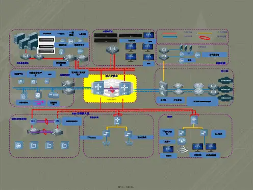
锐捷网络产品图标集交换机产品交换机产品核心交换机模块化汇聚 交换机固化汇聚 交换机接入交换机三层堆叠 交换机二层堆叠 交换机路由器产品路由器产品高端路由器中低端 路由器VOICE多业务 路由器SOHO多业务 路由器IPv6多业务 路由器无线产品无线产品无线交换机单路AP双路AP室外天线室外天线-2无线网桥-01无线网桥-02无线网卡-01无线网卡-02笔记本+无线 网卡-01 网卡 01笔记本+无线 网卡-02 网卡 02安全产品安全产品IDS入侵 检测系统IPS入侵 防御系统防火墙-01防火墙-02 防火墙VPN网关 关USB Key加密锁加密隧道-01加密隧道-02VPN客户端软件空白光盘钥匙证书-01证书-02存储产品存储产品磁带库磁盘阵列存储控制器 2U可扩展存储控制器 盘柜 控制器+盘柜3U可扩展存储存储产品1U存储2U存储3U存储TOE卡FC HBA卡FCoE卡 FC光纤交换机 FCoE交换机存储产品Windows服务器UNIX服务器Linux服务器SUN服务器DELL服务器HP服务器IBM服务器通用服务器1通用服务器2存储 存储产品Informix数据库Oracle数据库SQL数据库通用数据库文件类数据邮件数据www数据OA数据通用数据VOD数据 数据ERP数据 数据HIS数据 数据PACS数据 数据应用系统产品应用系统产品IPC1IPC2SMPSU认证客户端SAMlimpPATSTMSelogenmIpfixSNCSNC2其他其他万兆光纤线10G万兆双绞线R:187 B:1 G:50 size:6pt10G千兆线光纤线R:240 B:131 G:0 size:6pt1000M千兆线双绞线R:0 B:240 G:131 size:4pt1000MR:0 B:160 G:233 size:4pt其他百兆线光纤线100M百兆线双绞线R:146 B:8 G:131 size:3pt R:232 B:82 G:152 i 3 t R 232 B 82 G 152 size:3pt100M十兆线光纤线10M十兆线双绞线R:230 B:0 G:19 size:2pt10MR:252 B:199 G:0 size:2pt广域网线R:167 B:188 G:199 size:1pt制图规范-坐标系统 制图规范 坐标系统所有图标均为俯视图,偏转角度见上图Page20。