欧姆龙OMRON显示灯按钮开关MC
- 格式:pdf
- 大小:510.97 KB
- 文档页数:6

O M R O N欧姆龙光电开关型大全The latest revision on November 22, 2020OMRON欧姆龙光电开关(1号整经机)E3JK-DS30M1扩散反射型检测距离30CMOMRON欧姆龙光电开关1.E3JK-R2M1回归反射型检测距离2M2.E3JK-R4M1回归反射型检测距离4M3.E3JK-R4M2回归反射型检测距离4M4. E3JK-5M1对射型检测距离5M5.E3JK-5M2对射型检测距离5M6.E3JK-DS30M1扩散反射型检测距离30CM7. E3JM-10M4T定时型对射检测距离10M8.E3JM-10M4对射检测距离10M9.E3JM-10M4-G对射,检测距10M10. E3JM-DS70M4扩散反射型检测距离70CM11.E3JM-DS70M4-G扩散反射型检测70CM12. E3JM-R4M4T-G定时型回归反射检测距离4M13.E3JM-R4M4-G回归反射检测距离4M14.OMRON欧姆龙光电开关E3F3-D11φ18扩散反射型检测距离10CM/DC10-30V15.E3F3-D12φ18扩散反射型检测距离30CM/DC10-30V16. E3F3-R61φ18回归反射检测距2M/DC10-30V17.E3F3-T61φ18对射型检测距离10M/DC10-30V18. E3S-2E4对射型检测距离2M/DC10-30V19.E3S-2E4对射型检测距离5M/DC10-30V20.E3S-AD11扩散反射型检测距离20CM/DC10-30V21.E3S-AD61扩散反射型/DC10-30V22. E3S-AR61回归反射DC10-30V23.E3S-AR11回归反射检测距离2M/DC10-30V24. E3S-AT11对射型检测距离7M/DC10-30V25.E3S-AT61对射型/DC10-30V26. E3S-CL22M E3S-DS10E4扩散反射型检测距10CM/DC10-30V27.E3S-DS10E41扩散反射型检测距离10CM/DC10-30V28.E3S-GS1E4槽型检测距离10MM/DC10-30V29.E3S-GS3E4槽型检测距离30M/DC10-30V E3S-GS3B4槽型检测距离30M/DC10-30V30.E3R-5E4对射型检测距离5M/DC10-30V31. E3R-DS30E4扩散反射型检测距离30CM/DC10-30V32.E3R-R2E4回归反射型检测距离2M/DC10-30V33.OMRON欧姆龙光电开关E3Z-D61扩散反射型检测距离100M/DC10-30V34.E3Z-D62扩散反射型检测距离100M/DC10-30V35.E3Z-D81扩散反射型检测距离100M/DC10-30V36.E3Z-D82扩散反射型检测距离100M/DC10-30V37.E3Z-R61回归反射型检测距离4M/DC10-30V38.E3Z-R82回归反射型检测距离4M/DC10-30V39. E3Z-T61对射型检测距离15M/DC10-30V40.OMRON欧姆龙光纤放大器E3X-A11通用型NPN输出DC10-30V41.E3X-NA11通用型NPN输出DC10-30V42. E3X-NA41通用型PNP输出DC10-30V43.E3X-NM11通用型NPN输出DC10-30V,4路输出。
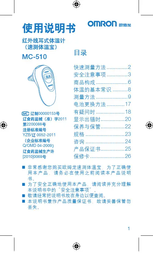
1MC-510目录快速测量方法 (2)安全注意事项 (3)商品构成 (6)体温的基本常识 (8)测量方法 (9)电池更换方法 (17)有疑问时 (18)显示出错时 ................20保养与保管 ................22规格 ..........................23咨询 .. (24)产品保证书 (25)保修卡 .......................26非常感谢您购买欧姆龙速测体温宝,为了正确使 ⏹用本产品,请务必在使用之前阅读本产品说明书。
为了安全正确地使用本产品,请阅读并充分理解 ⏹本说明书中的“安全注意事项”。
敬请经常把说明书放在身边以便查阅。
⏹本说明书兼作产品质量保证书,故请妥善保管勿 ⏹丢失。
快速测量方法3说明书中所表示的警告记号和警告图例,其目的 ⏹是为了使您能够安全、正确地使用本产品,并防止对您及他人造成伤害。
警告记号、图例及其含义如下:⏹※ 所谓物品损坏是指有关房屋、家产及家畜、宠物的损害。
安全注意事项45建议• 当您把所测体温告诉医生时,请说明您是用耳式体温计进行测量的。
• 请不要用于人体耳部以外的体温测量。
• 请不要强行碰撞、摔落、踩踏和摇动本体。
•请勿在测量过程中在体温计附近使用移动电话。
• 请勿拆卸、修理和改造本体。
• 本产品不防水。
请注意不要让液体(酒精、水滴、热水等)进入本体内部。
6☆ 探测器保护罩是消耗品,使用完结后请购买新的探测器保护罩。
☆ 探测器保护罩脏污破损时,请更换探测器保护罩,因为表面的脏污和破损会影响测量精度。
78体温的基本常识测量腋下和舌下的体温易受外界温度、汗水和唾液等的影响,所以较之所测的温度偏低,而测量耳温可更好地反映脑部温度,快速测得正确的体温值。
为了正确判断发烧的状态,请了解正常情况下家庭成员的耳温。
耳温和腋下温度分布了解家庭成员正常状态时耳温。
耳温与腋下温度存在差异,通过正常状态时耳部与腋下的「温度差」可以大致比较出发烧时的「温度差」。

CSM_MY_DS_C_7_1微型功率继电器MY通用继电器最畅销的MY新增了回路检查用带闭锁摆杆型系列•无铅,更环保。
•取得VDE 标准(德国)认证。
•通过对AC/DC 线圈胶带颜色的改变,大大提高了AC/DC 规格的识别性。
•新增便于检查回路的带闭锁摆杆型MY(S)。
请参见“继电器共通注意事项”。
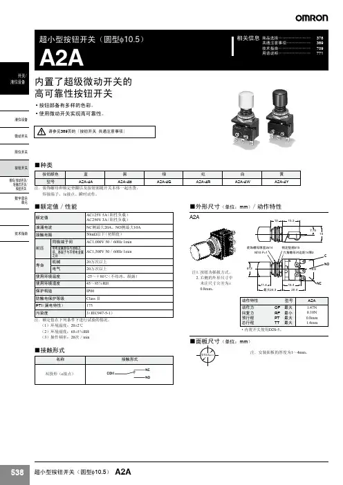
型号结构注1.表中的型号为UL/CSA 认证产品。
产品带有认证标记。
(高接触可靠型、塑料密封型、闭锁型、密闭型除外)2.表中带*的型号为新版本型号。
3.插座端子的标准型、线圈浪涌吸收用二极管型、线圈浪涌吸收用CR 回路型与PYF-E/PYFS (2极/4极)的组合符合“EC 适合宣言”。
产品带有“CE 标记”。
4.斜线部分无相应型号。
― 线部分产品的制作详情,请向经销商咨询。
关于插座端子型和插座的组合,请参见第33页上的“■选装件”中的z 连接插座、固定支架选型表。
微型功率继电器 MY2种类注1.关于订货生产规格的交货期,请向经销商咨询。
2.关于上述线圈规格以外的线圈电压型号,请向经销商咨询。
3.上述型号、规格为MY 新版本的对象产品。
4.除MY2(N)-CR 型号的上述电压规格以外,继电器高度为53mm 以下。
使用固定支架时,请参照33页进行选定。
额定规格/性能■ 额定规格z 操作线圈(标准型)注1.额定电流、线圈电阻值指的是线圈温度为+23°C 时的值。
公差为AC 额定电流+15%、−20%、DC 线圈电阻±15%。
2.AC 线圈电阻、电感的值为参考值。
(60Hz 时)3.动作特性指的是线圈温度为+23°C 时的值。
4.最大容许电压指的是环境温度为+23°C 时的值。
*1.各产品均有差异,实效值在80%以下。
为了确保正常动作,请外加额定值80%以上的电压。
(线圈温度为+23°C 时)*2.各产品均有差异,实效值在AC30%以下、DC10%以上。
为确保正常复位,请将电压降至该值以下。
欧姆龙光电开关说明书1. 引言欧姆龙光电开关是一种利用光电传感器技术实现的开关设备,通过检测光线的变化来判断是否触发开关动作。
本说明书将详细介绍欧姆龙光电开关的技术原理、使用方法、注意事项以及维护保养等内容,以帮助用户合理、安全地使用该设备。
2. 技术原理欧姆龙光电开关采用了光电传感器技术,在光电传感器中,包含了一对光源和光敏元件。
当遮挡物体经过检测区域时,光敏元件将接收到的光信号发生变化,从而触发开关动作。
光电开关通常有两种工作方式:逻辑输出和模拟输出,具体的输出信号可以根据用户需求进行设置。
3. 使用方法a)安装根据实际需求,将光电开关安装到需要检测的位置上,确保光敏元件可以正常接收到被检测物体通过的光信号。
注意避免外部光源对光敏元件产生干扰,可以通过合理选择安装位置和使用遮光罩等方式来减少干扰。
b)连接将光电开关与电路连接,确保电路连接正确且稳定。
通常光电开关需要使用直流电源进行供电,电压范围根据具体型号来确定。
c)设置根据实际应用需求,设置光电开关的工作方式、触发灵敏度等参数。
欧姆龙光电开关通常提供了相应的参数调节装置,用户可以根据需要进行调整。
d)测试完成安装、连接和设置后,进行测试以确保光电开关正常工作。
可以通过手动触发被检测物体通过检测区域,观察开关的触发情况,根据实际需求进行调整。
4. 注意事项a)使用过程中请确保电源电压符合设备要求,避免超过额定电压范围。
b)在使用过程中请避免将光电开关安装在高温、潮湿等有害环境中,以免影响设备的正常工作。
c)避免遮挡光敏元件,在使用过程中请确保光敏元件处于正常工作状态,避免被阻挡物体遮挡。
d)避免外部光源干扰,在安装过程中请注意避免强光直射到光敏元件上,可以使用遮光罩等方式来减少光源干扰。
e)检查设备连接是否牢固,确保所有连接处都紧固可靠,避免松动引起的工作异常。
f)如设备出现故障,请及时联系专业维修人员进行处理,避免私自拆解修理。
5. 维护保养a)定期清洁光敏元件,可以使用干净的棉签轻轻擦拭。
«电工技术» 2002年1期 OMRON 光电传感器 调节与设定重庆大学电气工程学院 廖常初[摘要]以OMRON的光电传感器为例,介绍了光电传感器常见的调节和设定方法。
关键词 传感器 光电 调节为了保证光电传感器功能的实现,降低调试难度,减少调试时间,现代光电传感器设置了很多调节功能,给使用者带来了极大的方便。
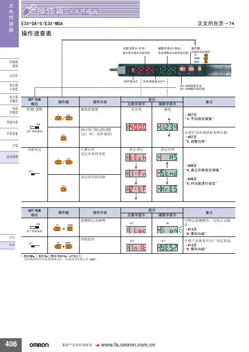
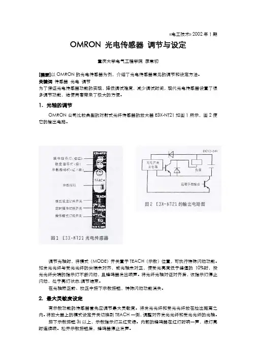
1.光轴的调节OMRON公司比较典型的对射式光纤传感器的放大器E3X-NT21如图1所示,图2使它的输出电路。
调节光轴时,将模式(MODE)开关置于TEACH(示教)位置,可执行特殊闪动功能。
如发光光纤与受光光纤的尖端未对齐,或光轴未对正,使受光亮度低于峰值的10%时,投光光纤尖端的指示灯不断闪动,且蜂鸣器发出响声。
将光纤光轴对证对齐后,该指示灯停止闪动,处于亮灯状态,调节结束。
在光轴矫正前、校正中按下示教按钮,特殊闪动功能消失。
2.最大灵敏度设定有示教功能的传感器首先应调节最大灵敏度。
将发光光纤和受光光纤放在检出距离之内。
将放大器上的模式设定开关切换到TEACH一侧,调整对齐发光光纤和受光光纤的光轴。
按下示教按钮3s以上,示教指示灯三红变绿。
内部的蜂鸣器在红灯时响一声,绿灯亮时连续响。
松开示教按钮后,蜂鸣器停止发声。
将模式切换开关切换到RUN位置,最大灵敏度设定结束。
示教指示灯熄灭。
设定最大灵敏度时,与光纤间的距离,是入光还是遮光无关。
用动作模式切换开关设定希望的逻辑输出。
若开光置于L.ON(Light ON),受光时输出为ON,若置于D.ON( Dark ON),遮光时输出为ON。
3.无工作示教示教(TEACH)功能用来检测背景光的强度或光泽度,以消除背景光的影响,使传感器能正确分辨出被检测物的有无,或分辨光量、光泽的变化。
无工件示教时,将发光光纤和受光光纤放在检出距离之内,放大器上的模式设定开关切换到TEACH一侧,调整对齐发光光纤和受光光纤的光轴。
无被检测物时按下示教按钮0.5~2.5s,示教指示灯红灯亮,内部的蜂鸣器响一声。
欧姆龙按钮
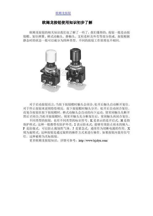
欧姆龙按钮使用知识初步了解
欧姆龙按钮的相关知识我们也了解了一些了,我们懂得的,按钮一般是由按钮帽、复位弹簧、桥式动触头、静触头、支柱连杆及外壳等部分组成。
按钮根据静态时的状态一般可以被分为四种类型。
不同的按钮工作原理也不相同。
对于启动按钮而言,当按下按钮帽时触头会闭合,松开后触头自动断开复位。
对于停止按钮来说则恰恰相反,按下按钮帽时触头分开,松开后自动闭合复位。
而复合按钮在按下按钮帽时,桥式动触头会自动的向下运动,使常闭触头先断开然后才闭合;当松开按钮帽时,则常开触头先分断复位后,常闭触头再闭合复位。
不同类型的按钮,也有不同类型的标识符号。
K是表示的是开启式。
H是指保护样式,这种一般都带有防护外壳。
S表示防水式,能够有效防止雨水的倾入。
F是防腐式,可以防止腐蚀性气体。
J是紧急式,通常作为切断电源的作用。
X 则为旋转式,这种按钮是通过旋转的操作方式来进行操作。
如果按钮内装有信号灯,这种被称为光标按钮。
更多欧姆龙按钮知识,详情可参考:/。

精心整理1如何获得血压计的读数概要此款OMRONMX3Plus电子血压计不适合去测量心脏跳动的频率。
怀孕期间、脉搏无规律和动脉异常等类似影响测量的,请求教你的医生。
测量前避免吃饭、饮酒、吸烟、运动和洗澡。
测量前和测量中应保持平静、放松。
你决不能不听从医生的吩咐而改变所服用的药剂剂量。
将此款血压计保存于温度–20℃至60℃之间的干燥、封闭的地方。
如果3个月或更长时间不使用,请将所有电池从电子血压计中取出。
使用时的劝告一天至少检查你的血压两次(早餐前、工作后)。
当你在车上时,不要测量你的血压。
请始终在同一个手臂上测量血压。
在测量前,将“布袖口”缠好在手臂上。
警告使用环境温度在10℃至40℃。
使用中避免剧烈振动、撞击、磁场、电器干扰及其它。
不可在强烈日光下测量。
测量期间与移动电话保持至少5米远。
不要将“布袖口”缠绕在除手臂之外的其它物品上。
不要将“布袖口”和管子折叠。
不要将OMRONMX3Plus血压计摔落。
2视图A显示屏B记忆按钮C开始按钮D开关按钮E交流电源插口F布袖口G气管H气管插头J电池盒K气管插口3准备工作⑴滑开电池盖。
⑵按照图示插四节电池进电池盒,并合上电池盒。
注意!必须是四节相同的AALR61.5V碱性电池!连接布袖口使布袖口缠绕好注意!当布袖口没有缠绕好手臂时,不要使布袖口膨胀!如上图,将H(气管插头)插入K(气管插口)⑴除去手臂上衣物注意!卷起袖子时,切勿压迫血液流动!⑵将布袖口一端穿过H(金属环)注意!不要将气管裹入⑶手臂穿过布袖口布袖口内!注意!如测量左臂,使气管与手臂、中指保持平行!如上图;如测量右臂,则将气管与右手的小手指保持平行!如左图。
布袖口下端与肘关节保持1至2厘米!⑷捏住布袖口末端,将它绕在手臂上,如左图。
注意!确信布袖口很好的裹住、粘好,否则不得膨胀布袖口压迫手臂!4Operation操作过程控制程序P低压数值(毫米汞柱)B记忆按钮Q记忆显示:存储中的记录C开始按钮数据D开关按钮R脉搏:每分钟心跳次数测量屏幕S没电:电力太弱或耗尽M高压数值T泄压:布袖口压力降低、(毫米汞柱)测量完毕N心脏符号:U膨胀:布袖口膨胀、测闪烁-仪器测量量仪器启动长亮-测量完毕V记忆位置:1至14注意!在连续两次测量中,应有最短三分钟的一个间隔!1坐在舒适的桌子2放松你的手臂,并将旁,双脚平放在地手掌心朝上。
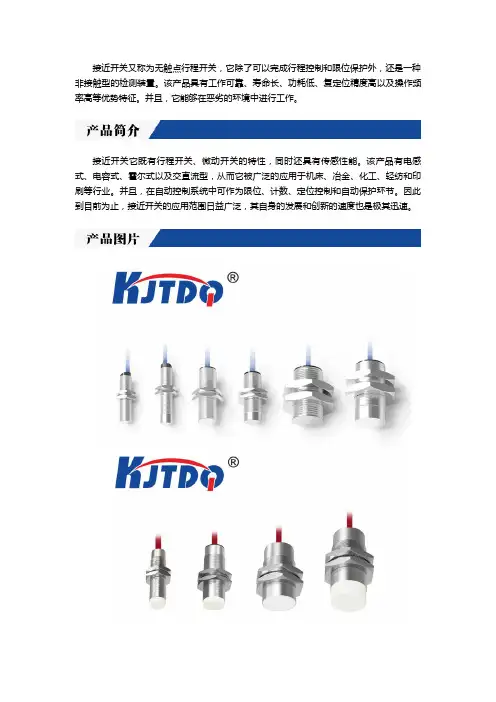
接近开关又称为无触点行程开关,它除了可以完成行程控制和限位保护外,还是一种非接触型的检测装置。
该产品具有工作可靠、寿命长、功耗低、复定位精度高以及操作频率高等优势特征。
并且,它能够在恶劣的环境中进行工作。
接近开关它既有行程开关、微动开关的特性,同时还具有传感性能。
该产品有电感式、电容式、霍尔式以及交直流型,从而它被广泛的应用于机床、冶金、化工、轻纺和印刷等行业。
并且,在自动控制系统中可作为限位、计数、定位控制和自动保护环节。
因此到目前为止,接近开关的应用范围日益广泛,其自身的发展和创新的速度也是极其迅速。
一、接近开关的主要功能1.检验距离检测电梯、升降设备的停止、起动、通过位置;检测车辆的位置,防止两物体相撞检测;检测工作机械的设定位置,移动机器或部件的极限位置;检测回转体的停止位置,阀门的开或关位置;检测气缸或液压缸内的活塞移动位置。
2.尺寸控制金属板冲剪的尺寸控制装置;自动选择、鉴别金属件长度;检测自动装卸时堆物高度;检测物品的长、宽、高和体积。
3.检测物体存在有否检测生产包装线上有无产品包装箱;检测有无产品零件。
4.转速与速度控制控制传送带的速度;控制旋转机械的转速;与各种脉冲发生器一起控制转速和转数。
5.检测异常检测瓶盖有无产品合格与不合格判断;检测包装盒内的金属制品缺乏与否;区分金属与非金属零件;产品有无标牌检测;起重机危险区报警;安全扶梯自动启停。
6.计量控制产品或零件的自动计量;检测计量器、仪表的指针范围而控制数或流量;检测浮标控制测面高度,流量;检测不锈钢桶中的铁浮标;仪表量程上限或下限的控制;流量控制,水平面控制。
二、接近开关的选型对于不同的材质的检测体和不同的检测距离,应选用不同类型的欧姆龙接近开关,以使其在系统中具有高的性能价格比,为此在选型中应遵循以下原则:1.当检测体为金属材料时,应选用高频振荡型欧姆龙接近开关,该类型欧姆龙接近开关对铁镍、A3钢类检测体检测最灵敏。
2.当检测体为非金属材料时,如木材、纸张、塑料、玻璃和水等,应选用电容型欧姆龙接近开关。
欧姆龙各类开关相关信息OMRON欧姆龙光电开关E3JK-R2M1 回归反射型,检测距离2ME3JK-R4M1 回归反射型,检测距离4ME3JK-R4M2 回归反射型,检测距离4ME3JK-5M1 对射型,检测距离5ME3JK-5M2 对射型,检测距离5ME3JK-DS30M1 扩散反射型,检测距离30CME3JM-10M4T 定时型对射,检测距离10ME3JM-10M4 对射,检测距离10ME3JM-10M4-G 对射,检测距离10ME3JM-DS70M4 扩散反射型,检测距离70CME3JM-DS70M4-G 扩散反射型,检测距离70CME3JM-R4M4T-G 定时型回归反射,检测距离4ME3JM-R4M4-G 回归反射,检测距离4MOMRON欧姆龙光电开关 E3F3-D11 φ18扩散反射型,检测距离10CM/DC10-30V E3F3-D12 φ18扩散反射型,检测距离30CM/DC10-30VE3F3-R61 φ18回归反射,检测距离2M/DC10-30VE3F3-T61 φ18对射型,检测距离10M/DC10-30VE3S-2E4 对射型,检测距离2M/DC10-30VE3S-2E4 对射型,检测距离5M/DC10-30VE3S-AD11 扩散反射型,检测距离20CM/DC10-30VE3S-AD61 扩散反射型/DC10-30VE3S-AR61 回归反射,DC10-30VE3S-AR11 回归反射,检测距离2M/DC10-30VE3S-AT11 对射型,检测距离7M/DC10-30VE3S-AT61 对射型/DC10-30VE3S-CL2 2ME3S-DS10E4 扩散反射型,检测距离10CM/DC10-30V E3S-DS10E41 扩散反射型,检测距离10CM/DC10-30V E3S-GS1E4 槽型,检测距离10MM/DC10-30VE3S-GS3E4 槽型,检测距离30M/DC10-30VE3S-GS3B4 槽型,检测距离30M/DC10-30VE3R-5E4 对射型,检测距离5M/DC10-30VE3R-DS30E4 扩散反射型,检测距离30CM/DC10-30V E3R-R2E4 回归反射型,检测距离2M/DC10-30V OMRON欧姆龙光电开关E3Z-D61 扩散反射型,检测距离100M/DC10-30VE3Z-D62 扩散反射型,检测距离100M/DC10-30VE3Z-D81 扩散反射型,检测距离100M/DC10-30VE3Z-D82 扩散反射型,检测距离100M/DC10-30VE3Z-R61 回归反射型,检测距离4M/DC10-30VE3Z-R82 回归反射型,检测距离4M/DC10-30VE3Z-T61 对射型,检测距离15M/DC10-30VOMRON欧姆龙光纤放大器E3X-A11 通用型NPN输出DC10-30VE3X-NA11 通用型NPN输出DC10-30VE3X-NA41 通用型PNP输出DC10-30VE3X-NM11 通用型NPN输出DC10-30V,4路输出E3X-NT11 通用型NPN输出DC10-30VE3X-DA11-S 通用型NPN输出DC10-30VE3X-DA11-N 通用型NPN输出DC10-30VE3X-X3CE4 光纤式DC10-30VE3X-VS1E4 光纤式DC10-30V欧姆龙接近开关 LJ8A3-2-Z/BX 10-30VDC欧姆龙接近开关 LJ8A3-2-Z/AX 10-30VDCOMRON欧姆龙直流二线接近开关E2EZ-X2D1-N Φ8二线常开10-30VDC检测距离2mmE2EZ-X3D1-N Φ12二线常开10-30VDC检测距离2mmE2EZ-X3D2-N Φ12二线常闭10-30VDC检测距离2mmE2EZ-X4MD1 Φ8二线常闭10-30VDC检测距离4mmOMRON欧姆龙接近开关 E2E-X5F1 Φ18三线直流NPN常开10-30VDC检测距离mm OMRON欧姆龙接近开关 E2E-X5ME1 Φ18三线直流NPN常开10-30VDC检测距离mm OMRON欧姆龙接近开关 E2E-X10ME1 10-30VDC三线常开NPNOMRON欧姆龙接近开关 E2E-X10ME1-Z 10-30VDC三线常开NPNOMRON欧姆龙接近开关 E2E-X10MY1 Φ18交流二线常开OMRON欧姆龙接近开关 E2E-X18ME1 Φ30/10-30VDC/2M线三线常开NPN OMRON欧姆龙磁性接近开关 E3X-ZA11OMRON欧姆龙接近开关 TL-Q5MC1-Z 直流三线NPN NOTL-Q5MY2 交流三线NPN NOOMRON欧姆龙接近开关 TL-W3MC1OMRON欧姆龙接近开关 TL-N10ME1OMRON欧姆龙接近开关 TL-N10MY1 交流二线常开更多欧姆龙接近开关知识,详情可参考:/。
Joystick SwitchesQuality, reliability, precision Quality, reliability and precision are the hallmarks of our corporate philosophy.They represent concepts and values to which we feel totally committed. At EUCHNER, quality means that all our employees take personal respon-sibility for the company as a whole and, in particular, for their own field of work. This individual commitment to perfection results in products which are ideally tailored to the customers’needs and the requirements of the market. After all: our customers and their needs are the focus of all our efforts. Through efficient and effective use of resources, the promotion of personal initiative and courage in find-ing unusual solutions to the benefit of our customers, we ensure a high level of customer satisfaction. We familiar-ize ourselves with their needs, require-ments and products and we learn from the experiences of our cus-tomers’ own customers.EUCHNER – More than safety.Quality –made by EUCHNERMore than safety.Around the world –the Swabian specialists in motion sequence control for mechanical and sys-tems engineering.EUCHNER’s history began in 1940 with the establishment of an engineering office by Emil Euchner. Since that time, EUCHNER has been involved in the design and development of switch-gear for controlling a wide variety of motion sequences in mechanical and systems engineering. In 1953, Emil Euchner founded EUCHNER +Co., a milestone in the company’s history. In 1952, he developed the first multiple limit switch –to this day a symbol of the enterprising spirit of this family-owned company.Automation –Safety –ManMachine Today, our products range from electromechanical and electronic components to complex system solu-tions. With this wide range of products we can provide the necessary tech-nologies to offer the right solution for special requirements – regardless of whether these relate to reliable and precise positioning or to components and systems for safety engineering in the automation sector.EUCHNER products are sold through a world-wide sales network of compe-tent partners. With our closeness to the customer and the guarantee of reliable solutions throughout the globe, we enjoy the confidence of cus-tomers all over the world.Emil Euchner, the company’s founder and inventor of the multiple limit switch, circa 1928.ManMachineTable of contents Joystick switchesDesign and function4Advantages/features4Series5Series WK...Control panel installation to IEC 947-5-1 D306Series WE...Control panel installation at rear or with front plate8Series KB...Control panel installation to IEC 947-5-1 D3010Series KF...Control panel installation at rear12Series KE...Control panel installation to IEC 947-5-1 D2214Series KC...Control panel installation at rear or with front plate16Series KP...Analog JoystickControl panel installation at rear or with front plate19Universal Power Supply Unit P1/P2 for series KP joysticks22Housing HBL23Housing HBE24Front plates for housing HBL and HBE25 Technical status 09-03/06ApplicationJoystick switches or joysticks are manually actuated control devices for installation in control and front panels as well as in portable control equipment. They are used wherever motion sequences analogous to the actuation direction are controlled by hand. They are ideal for raising, lowering and triggering movements to the right and left, just to name same few possibilities.EUCHNER joysticks are used in the steel and construction industry, in machine tools, for transport and conveyor systems, in thecertification, the devices are approved for use in the ship-building industry.EUCHNER joysticks are also used for radio and cable controls, building machinery and cranes.Joysticks as control equipment in remote control devicesDesign and functionMicroswitches with a step function response are used as switching elements. Due to the intermittent control, a clear switching function is given for precise control systems. Depending on the respective application, switching elements with a power rating of between 4mA and 16A can be used. These are fixed on the mounting plate for each different series, either individually or in groups. The switching elements are actuated by the joystick being moved out of the intermediate position. The robust levers made of stainless steel are bedded with a hinged ball bearing that is fixed in a front plate.Advantages/featuresDirection of movement: Simplification of the command control station Easy mounting due to the slots in the panel Small space requirement Long service lifeRobust and lasting constructionHigh potection class: IP 65 and beyondRemote cable control for concrete pumpsModelsEUCHNER joystick switches are available in a number of different models:Series WK...(page 6)Series WE...(page 8)Series KB...(page 10)Series KF ...(page 12)Series KE...(page 14)Series KC...(page 16)Series KP...(page 19)Housing kits (from page 22)suitable for series WK, KB, KE and KFActuatingdirectionsPanel cutoutPushbutton D(with protective cap)Interlock VBellows WClamping screws forpanel thickness (1 - 8 mm)Centre position switch Z (actuated in centre position)Connection D(the connection is located on the under-side for types with 8 directions)Series WK...Control panel installation to IEC 947-5-1 D301 to 8 actuating directions with spring return operation or combinedOne changeover contact with tab connector 2.8 x 0.5 IEC 760 for each actuating direction Centre position switch Pushbutton in handleDimension drawingGermanischer LloydCertificate no. 17 041 - 00 HHOrdering codeSeriesActuating direction and switching behavior Stayput switch S (switching lever latches in selected position)Spring return switch T (switching lever returns to centre position)Options Pushbutton D Bellows W InterlockV Centre position switch Z All-round actuationRW KOrdering examples:Joystick switch series WK, actuating directions 1+3 stayput switch S,WK S13 T24 DZV actuating directions 2+4 spring return switch T, Pushbutton D, centre position switch Z,Interlock V in centre positionJoystick switch series WK, 8 switching elements as spring return switches, all-round actuation R WK T1-8 R DesignJoystick switch series WK, 4 switching elements, 2 actuating directions on request (2 switching elements per actuating direction)* Diagonal actuation of 4 adjacent switching elements is on request.Control panel installation and actuating directionsFront platePushbutton D(with protective cap)Interlock VBellows WConnection Series WE...Control panel installation at rear or with front plate1 to 8 actuating directions with stayput or spring return operation or combined One changeover contact with screw terminal for each actuating direction Centre position switch Pushbutton in handleDimension drawingGermanischer LloydCertificate no. 17 041 - 00 HHOrdering codeSeriesActuating direction and switching behavior Stayput switch S (switching lever latches in selected position)Spring return switch T (switching lever returns to centre position)Options Pushbutton D Bellows W InterlockV Centre position switch Z All-round actuation R Front plate FW EFront plate FOrdering examples:Joystick switch series WE, actuating directions 1+3 stayput switch S,WE S13 T24 DZV actuating directions 2+4 spring return switch T, Pushbutton D, centre position switch Z,Interlock V in centre positionJoystick switch series WE, 8 switching elements as spring return switches, all-round actuation R WE T1-8 R DesignJoystick switch series WE, 4 switching elements, 2 actuating directions on request (2 switching elements per actuating direction)Actuating directionsPanel cutoutInterlock V BellowsSeries KB...Control panel installation to IEC 947-5-1 D301 to 8 actuating directions, 4 switching elements. With stayput or spring return operation or combined One changeover contact with tab connector 6.3 x 0.8 IEC 760 for each actuating directionDimension drawingGermanischer LloydCertificate no. 17 041 - 00 HHOrdering codeSeriesActuating direction and switching behavior Stayput switch S (switching lever latches in selected position)Spring return switch T (switching lever returns to centre position)Options InterlockV All-round actuationR 1)1) Simultaneous actuation of 2 adjacent switching elements in diagonal actuating directions.KBOrdering examples:Joystick switch series KB, actuating directions 1+3 stayput switch S,KB S13 T24 actuating directions 2+4 spring return switch TJoystick switch series KB, actuating directions 1+3 spring return switch T,KB T13 V Interlock V in centre positionSeries KF ...Control panel installation at rear1 to 8 actuating directions, 4 switching elements. With stayput or spring return operation or combined One changeover contact with screw terminal for each actuating direction Centre position switchDimension drawingGermanischer LloydCertificate no. 17 041 - 00 HHOrdering codeSeriesActuating direction and switching behavior Stayput switch S (switching lever latches in selected position)Spring return switch T (switching lever returns to centre position)OptionsCentre position switch Z All-round actuation R 1)1) Simultaneous actuation of 2 adjacent switching elements in diagonal actuating directions.KFActuating directionsPanel cutoutOrdering examples:Joystick switch series KF, actuating directions 1+3 stayput switch S,KF S13 T24 Z actuating directions 2+4 spring return switch T, centre position switch ZJoystick switch series KF, actuating directions 1-4 spring return switch T,KF T1234 R all-round actuation RActuating directionsPanel cutoutInterlock VBellowsCentre position switch Z (actuated in centre position)Series KE...Control panel installation to IEC 947-5-1 D221 to 8 actuating directions, 4 switching elements. With stayput or spring return operation or combined One changeover contact with tab connector 2.8 x 0.5 IEC 760 for each actuating direction Centre position switchDimension drawingGermanischer LloydCertificate no. 17 041 - 00 HHOrdering codeSeriesActuating direction and switching behavior Stayput switch S (switching lever latches in selected position)Spring return switch T (switching lever returns to centre position)Options InterlockV Centre position switch Z All-round actuation R 1)1) Simultaneous actuation of 2 adjacent switching elements in diagonal actuating directions.KEOrdering examples:Joystick switch series KE, actuating directions 1+3 stayput switch S,KE S13 T24 Z actuating directions 2+4 spring return switch T, centre position switch ZJoystick switch series KE, actuating directions 1+3 spring return switch T,KE T13 V Interlock V in centre positionJoystick switch series KE, actuating directions 1-4 Spring return switch T,KE T1234 R all-round actuation RActuating directions Top view of actuating leverCentre position switch Z (actuated in centre position)Series KC...control panel installation at rear or with front plate1 to 8 actuating directions with 1 or2 switching positions for each actuating direction Switching positions as stayput or spring return operation in various combinationsCentre position switch Pushbutton in handleDimensiondrawingMain actuating directions1, 2, 3 and 4Diagonal actuating directions5, 6, 7 and 8Switching position ISwitching position IID V1)Panel cutout for assembly with bellows WX Germanischer LloydCertificate no. 17 041 - 00 HHOrdering examples: (see type code on page 18)Joystick switch series KC with tab connector, main actuating direction KCA3A5C005C0000V1 1 with 3 switching elements. As spring return switch in switching position I.As stayput switch in switching position II.Main actuating directions 2 and 4 with 2 switching elements each. As stayput switch in switchingpositions I and II. Main actuating direction 3 not used. Option V1 (mech. inter-lock from switching position I to switching position II)Joystick switch series KC with screw terminal, main actuating directions 1-4KCB4E4E4E4E5678DW as stayput switch. S with one switching element each, diagonal actuating directions 5-8,Pushbutton D, bellows W for panel mounting.Ordering codeSeriesConnection typeTab connector 2.8 x 0.5 IEC 760A Screw terminalBMain actuating direction 1Switching behavior 1)Switching function 2)Main actuating direction 2Switching behavior 1)Switching function 2)Main actuating direction 3Switching behavior 1)Switching function 2)Main actuating direction 4Switching behavior 1)Switching function 2)Diagonal actuating direction 5 3)Diagonal actuating direction 6 3)Diagonal actuating direction 7 3)Diagonal actuating direction 8 3)OptionsPushbutton in handleD Bellows for panel mounting W Bellows for surface mounting X Interlock switching position 0V0Interlock switching position I to II V1Centre position switch Z All-round actuationR1) See …Switching behavior “ table. Actuating directions which are not required must be marked with …0“.2) See …Switching functions “ table.3) Simultaneous actuation of 2 adjacent switching elements in diagonal actuating directions.K CSeries KC...Switching behavior 1)G Stayput switch (switching lever latches in selected position)Spring return switch (switching lever returns to initial position)Switching functions 2)1-23G 4G -5G G 6G I II0I II11A2F23311B 2G2311C 2H2331D 2K2331E2331Contact state in switching positionControl versionsCentre position switch Z (actuated in centre position)Series KP ...Analog Joystickcontrol panel installation at rear or with front plate Analog, proportional output signalsControl variants with 1 and 2 axes or 2 axes simultaneously Centre position switch Pushbutton in handleDimension drawing3D V1)Panel cutout for assembly with bellows WX Versions 1 = 1 axis Versions 2 = 2 axesVersions 3 = 2 axes simultaneously (only spring return version)Ordering codeSeriesControl variants 1 axis 12 axes22 axes simultaneously 3End position Stayput switchS Spring return switch TOptions PushbuttonD Bellows for panel mounting W Bellows for surface mounting X InterlockV Centre position switchZK PSeries KP ...Analog JoystickPin assignment-X (-Y)+X (+Y)+10V-10VConnection Centre position switchConnection PushbuttonInputOutput Y ± 10 V, 10 mA 0 V 0 V (GND)X± 10 V, 10 mA- V -18 V 0 V 0 V (GND)+ V+18 VOrdering example:Analog Joystick series KP for 2-axis control, limit position spring return switch T ,KP 2 TVWZmechanical interlock, V in zero position, bellows W for panel mounting,centre position switch Z in switching position zeroUniversal Power Suply Unit P1/P2 Order No. 096 645∅DTechnical dataOrdering tablePG 11073 098for heavy gauge cable gland PG 11, 6 screws for front plate attachment, cover frame PG 13.5Housing HBL, with magnetic clamp, hanging clip, fixing nut072 630for heavy gauge cable gland PG 13.5, 6 screws for front plate attachment, cover frameNote2 versions for different cable glandsPG 1119PG 13.520.8Hanging clipView AAMagnetic clampScrew depth max. 6.0 mm (valid for all fixing holes)Dimension drawing∅DTechnical dataOrdering tablePG 11048 429 for heavy gauge cable gland PG 11, 4 screws for front plate attachmentPG 13.5Housing HBE, with magnetic clamp, hanging clip, fixing nut072 626 for heavy gauge cable gland PG 13.5, 4 screws for front plate attachmentDimension drawingNotes2 versions for different cable glands View A AHanging clipMagneticclampPG 1119PG 13.520.8Technical dataOrdering tableFront plate for HBL housing, with seal 055 967Front plate for HBE housing, with seal052 954Front plates for housing HBL and HBE Front plates HBLFront plateFlat sealDimension drawingFront plates HBEFront plateFlat seal。
1如何获得血压计得读数概要此款OMRON MX3 Plus电子血压计不适合去测量心脏跳动得频率。
怀孕期间、脉搏无规律与动脉异常等类似影响测量得,请求教您得医生。
测量前避免吃饭、饮酒、吸烟、运动与洗澡。
测量前与测量中应保持平静、放松。
您决不能不听从医生得吩咐而改变所服用得药剂剂量。
将此款血压计保存于温度–20℃至60℃之间得干燥、封闭得地方。
如果3个月或更长时间不使用,请将所有电池从电子血压计中取出。
使用时得劝告一天至少检查您得血压两次(早餐前、工作后)。
当您在车上时,不要测量您得血压。
请始终在同一个手臂上测量血压。
在测量前,将“布袖口”缠好在手臂上。
警告使用环境温度在10℃至40℃。
使用中避免剧烈振动、撞击、磁场、电器干扰及其它。
不可在强烈日光下测量。
测量期间与移动电话保持至少5米远。
不要将“布袖口”缠绕在除手臂之外得其它物品上。
不要将“布袖口”与管子折叠。
不要将OMRON MX3 Plus血压计摔落。
2视图A显示屏 B 记忆按钮C开始按钮D开关按钮 E 交流电源插口 F 布袖口G气管H 气管插头J电池盒K 气管插口3 准备工作⑴滑开电池盖。
⑵按照图示插四节电池进电池盒,并合上电池盒。
注意!必须就是四节相同得AA LR61、5V碱性电池!连接布袖口使布袖口缠绕好注意!当布袖口没有缠绕好手臂时,不要使布袖口膨胀!如上图,将H(气管插头)插入K(气管插口)⑴除去手臂上衣物注意!卷起袖子时,切勿压迫血液流动!⑵将布袖口一端穿过H(金属环)注意!不要将气管裹入⑶手臂穿过布袖口布袖口内! 注意!如测量左臂,使气管与手臂、中指保持平行!如上图;如测量右臂,则将气管与右手得小手指保持平行!如左图。
布袖口下端与肘关节保持1至2厘米!⑷捏住布袖口末端,将它绕在手臂上,如左图。
注意!确信布袖口很好得裹住、粘好,否则不得膨胀布袖口压迫手臂!4 Operation操作过程控制程序 P低压数值(毫米汞柱) B记忆按钮 Q记忆显示:存储中得记录C开始按钮数据D开关按钮R脉搏:每分钟心跳次数测量屏幕S没电:电力太弱或耗尽M高压数值T泄压:布袖口压力降低、(毫米汞柱) 测量完毕N心脏符号: U膨胀:布袖口膨胀、测闪烁-仪器测量量仪器启动长亮-测量完毕 V记忆位置:1至14注意!在连续两次测量中,应有最短三分钟得一个间隔!1坐在舒适得桌子2放松您得手臂,并将旁,双脚平放在地手掌心朝上。
OMRON欧姆龙限位开关
接近开关是一种无需与运动部件进行机械直接接触而可以操作的位置开关,当物体接近开关的感应面到动作距离时,不需要机械接触及施加任何压力即可使开关动作,从而驱动直流电器或给计算机(plc)装置提供控制指令。
接近开关是种开关型传感器(即无触点开关),它既有行程开关、微动开关的特性,同时具有传感性能,且动作可靠,性能稳定,频率响应快,应用寿命长,抗干扰能力强等、并具有防水、防震、耐腐蚀等特点。
产品有电感式、电容式、霍尔式、交、直流型。
接近开关又称无触点接近开关,是理想的电子开关量传感器。
当金属检测体接近开关的感应区域,开关就能无接触,无压力、无火花、迅速发出电气指令,准确反应出运动机构的位置和行程,即使用于一般的行程控制,其定位精度、操作频率、使用寿命、安装调整的方便性和对恶劣环境的适用能力,是一般机械式行程开关所不能相比的。
它广泛地应用于机床、冶金、化工、轻纺和印刷等行业。
在自动控制系统中可作为限位、计数、定位控制和自动保护环节等。
OMRON欧姆龙限位开关。
1 如何获得血压计的读数概要此款OMRON MX3 Plus电子血压计不适合去测量心脏跳动的频率。
怀孕期间、脉搏无规律和动脉异常等类似影响测量的,请求教你的医生。
测量前避免吃饭、饮酒、吸烟、运动和洗澡。
测量前和测量中应保持平静、放松。
你决不能不听从医生的吩咐而改变所服用的药剂剂量。
将此款血压计保存于温度–20℃至60℃之间的干燥、封闭的地方。
如果3个月或更长时间不使用,请将所有电池从电子血压计中取出。
使用时的劝告一天至少检查你的血压两次(早餐前、工作后)。
当你在车上时,不要测量你的血压。
请始终在同一个手臂上测量血压。
在测量前,将“布袖口”缠好在手臂上。
警告使用环境温度在10℃至40℃。
使用中避免剧烈振动、撞击、磁场、电器干扰及其它。
不可在强烈日光下测量。
测量期间与移动电话保持至少5米远。
不要将“布袖口”缠绕在除手臂之外的其它物品上。
不要将“布袖口”和管子折叠。
不要将OMRON MX3 Plus血压计摔落。
2 视图A 显示屏B 记忆按钮C 开始按钮D 开关按钮E 交流电源插口F 布袖口G 气管 H 气管插头 J 电池盒 K 气管插口3 准备工作⑴滑开电池盖。
⑵按照图示插四节电池进电池盒,并合上电池盒。
注意!必须是四节相同的AA LR6 碱性电池!连接布袖口使布袖口缠绕好注意!当布袖口没有缠绕好手臂时,不要使布袖口膨胀!如上图,将H(气管插头)插入K(气管插口)⑴除去手臂上衣物注意!卷起袖子时,切勿压迫血液流动!⑵将布袖口一端穿过H(金属环)注意!不要将气管裹入⑶手臂穿过布袖口布袖口内!注意!如测量左臂,使气管与手臂、中指保持平行!如上图;如测量右臂,则将气管与右手的小手指保持平行!如左图。
布袖口下端与肘关节保持1至2厘米!⑷捏住布袖口末端,将它绕在手臂上,如左图。
注意!确信布袖口很好的裹住、粘好,否则不得膨胀布袖口压迫手臂!4 Operation操作过程控制程序 P低压数值(毫米汞柱)B记忆按钮 Q记忆显示:存储中的记录C开始按钮数据D开关按钮 R脉搏:每分钟心跳次数测量屏幕 S没电:电力太弱或耗尽M高压数值 T泄压:布袖口压力降低、(毫米汞柱) 测量完毕N心脏符号: U膨胀:布袖口膨胀、测闪烁-仪器测量量仪器启动长亮-测量完毕 V记忆位置:1至14注意!在连续两次测量中,应有最短三分钟的一个间隔!1坐在舒适的桌子 2放松你的手臂,并将旁,双脚平放在地手掌心朝上。