1 ESP surface equipment
- 格式:ppt
- 大小:80.50 KB
- 文档页数:3

长安福特常用缩写词(CP)Confirmation Prototype确认样车Final Status最终状态(J1)Job 1整车投产(PT)P/T Design Complete动力传动系统设计结束PT(P/T)Power Train动力传动系统(ST)Surface Transfer表面参数传递Change Cut-Off更改完成Launch Readiness投产准备就绪Launch Sign-Off投产验收Program Approval项目批准Proportions & Hardpoints比例与固定点Product Readiness产品准备就绪Pre Milestone 1SI前里程碑1Pre Milestone 2SI前里程碑2Strategic Confirmation策略确认Strategic Intent策略意向Strategic Planning策略计划(SP)Structural Prototype样车结构(TTO)Tool Try-Out工装设备试运行Global 8D Eight disciplinary ActionsG8D(福特公司解决问题的标准方法)14DMore Detailed than Global 8D (used to containand resolve stop-shipment/recall problems)更详细的细节(包括并解决停止运货/召回问题)1MIS One Month in Service投入使用1个月1PP First Production Proveout第一次试生产2PP Second Production Proveout第二次试生产3MIS Three Months in Service投入使用3个月4P Production Process Proveout Program生产程序验证项目AAA American Automobile Association美国汽车工业联合会ABS Affordable Business Structure可承受商业结构ABS Anti skid brake system防抱死制动系统AIAG Automotive Industry Action Group 机动车工业行动小组AIC Accelerated Implementation Centre快速实施中心AIM Automated Issues Matrix问题结构图AIMS Automated Issues Matrix System问题结构图系统AME Advanced Manufacturing Engineering先进制造工艺AMPPE Advanced Manufacturing Pre-Program Engineering 先进项目前制造工艺ANOVA Analysis of Variance多样性分析AP Attribute Prototype设计样车APEAL Automotive Performance Execution and Layout机动车性能实施与规划APQP Advanced Product Quality Planning先进产品质量计划ASQ American Society for Quality美国质量协会AV Appraiser Variation评估者的多样性AVT Advance Vehicle Technology先进车辆技术AWS Analytical Warranty System分析性的保修系统AXOD Automatic Transaxle Overdrive Transmission自动变速驱动桥超速档传动系B&ABody & Assembly Operations (New Term: VehicleOperations)车身与组装操作(新术语:车辆操作)BCG Business Consumer Group消费者工作组BIC Best in Class等级中的最佳BIS Body Shop Information System车身工作间信息系统BLI Business Leadership Initiative领导层初始意向BOM Bill OfMaterials零件清单BTB Bumper-to-Bumper保险杠到保险杠BTS Build-To-Schedule按日程建造BUR Business Unit Review业务小组讨论CAS Capacity Analysis Sheet能力分析表C/E Cause & Effect成因及影响CA Customer Attribute消费者特性CAD Computer Aided Design计算机辅助设计CAE Computer Aided Engineering计算机辅助工程CAP Corrective Action Plan纠正行动计划CBG Consumer Business Group消费者业务小组CB Continuous Build连续性生产CC Critical Characteristic评价特性CC Courtesy Copy抄送CC Carbon Copy副本CCC Customer Concern Classification客户问题分类CCC China compulsory certification中国强制认证CDS Component Design Specification零件设计参数CET Campaignable Events Team召回情况小组CETs Common External Tariff普通关税CETP Corporate Engineering Test Procedures公司工程测试程序CFR Constant Failure Rate连续故障率CHFCIM Computer Integrated Manufacturing计算机综合制造CIWG Continuous Improvement Work Group持续改进工作组CL Centerline中心线CMM Coordinate Measuring Machine协调测量设备CMMS Common Material Management System通用材料管理系统CMMS3Common Manufacturing Management System-3通用制造管理系统-3Code X Pre-build focusing on exterior components制造前关注的外部零件Code Y Pre-build focusing on interior components制造前关注的内部零件CP Cost plan(马自达用语)由ECN引起的价格变动估计CP Common Position通用位置CP Confirmation prototype确认样车(FORD 时间节点)C p Relates the allowable spread of thespecification limits to the measure of theactual variation of the process.将参数限制允许限度下的展开与程序实际多样性联系起来CPE Chief Program Engineer首席项目工程师C pk Measures the process variation with respect tothe allowable specification, and takes intoaccount the location of the process average测量程序的多样性并将其考虑到程序平均性的位置中CPU Cost Per Unit单位成本CQDC Corporate Quality Development Center公司质量开发中心CQIS Common Quality Indicator System一般质量指标系统CR Concern Responses问题回复CRT Component Review Team零件讨论组CSA Corporate Security Administrator公司安全管理员CSI Customer Service Index客户服务指数DCO Duty Cycle Output责任循环结果DCP Dynamic Control Planning动态控制计划DDL Direct Data Link直接数据连接Df Degrees of Freedom自由度DFA Design for Assembly总成设计DFM Design for Manufacturability制造能力设计DFMEA Design Failure Mode Effects Analysis故障模式影响分析设计DFR Decreasing Failure Rate故障下降率DMA Database Maintenance Administrator数据库维护管理人员DOE Design of Experiment试验设计DOM Dealer Operations Manager经销商业务经理DP Design Parameters参数设计DQR Durability Quality and Reliability耐久性质量与可靠性DTD Dock to Dock码头至码头DTD Design to Delivery设计到交付DCV Design Confirmation Vehicle设计确认车DV Design Verification设计验证DVM Design Verification Method设计验证方式DVP Design Verification Plan设计验证计划Design Verification Process and Production设计验证程序和产品验证DVP&PVValidationDVP&R Design Verification Plan & Report设计验证计划和结果DVPR Design Verification & Product Reliability设计验证和产品可靠性DVPV Design Verification and Process Verification设计验证和程序验证EAO European Automotive Operations欧洲机动车协会EASI Engineering And Supply Information工程和供应信息ECAR Electronic Connector Acceptability Rating电子连接接受比率EDI Electronic Data Interchange电子数据交换EESE Electrical and Electronic Systems Engineering电力及电子系统工程EMM Expanded Memory Manager扩展内存管理器EMS Environmental Management System环境管理系统EOL End of Line线的端点EQI Extraordinary Quality Initiative特别初始质量ES Engineering Specifications工程参数ESI Early Supplier Involvement早期供应商参与ESP Extended Service Plan延期服务计划ESTA Early Sourcing Target Agreement早期选点目标协议ESWP Early Sourcing Work Plan早期选点工作计划EV Equipment Variation设备变更F&T Facility & Tooling工装设备FACT Facilitation and Certification Training简易化及认证培训FASS Field Action/Stop Shipment区域行动/停止运货区域行动/停止运货(优先使用缩FA/SS Field Action/Stop Shipment (Preferred Acronym)写)FAO Ford Automotive Operations福特机动车协会FAP Ford Automotive Procedure福特机动车程序FAQ Frequently Asked Questions常见问答FCPA Ford Consumer Product Audit福特客户产品审核FCSD Ford Customer Service Division福特客户售后服务分枝机构FDVS Ford Design Verification System福特设计验证系统FER Fresh Eyes Review其它行业人员论证FER Final Engineering Review最终工程论证FEU Field Evaluation Unit区域评估组FIFO First in First Out先进先出FMEA Failure Mode Effects Analysis故障模式影响分析FMVSS Federal Motor Vehicle Safety Standards美国联邦机动车安全标准FPDS Ford Product Development System福特产品开发系统FPS Ford Production System福特生产系统FPSI Ford Production System Institute福特产品系统学院FPS IT Ford Production System Information Technology福特产品系统信息技术FOB Ford of Britain福特英国FQRs Frequent Quality Rejects经常性质量不合格品FR Functional Requirements功能要求FAO (福特机动车运作) 可靠性指FRG FAO Reliability Guide导FS Final Sign-off最终验收FSIC Ford System Integration Council福特系统综合委员会FSN Ford Supplier Network福特供应商网络FSS Full Service Suppliers全方位服务供应商FTDC Fairlane Training and Development Center培训和发展中心FTEP Ford Technical Educational Program福特技术培训项目FTT First Time Through首次通过FUNC-APPRV Functional Approvals功能批准FVEP Finished Vehicle Evaluation Program下线车辆评估项目GAP Global Architecture Process全球建筑设计程序GC Global Craftsmanship全球技术工艺GCARS Global Craftsmanship Attribute Rating System全球技术特性评分系统GCEQ Global Core Engineering Quality全球核心工程质量GEM Generic Electronic Module通用电子模块GIS1Global Information Standards全球信息标准Global Prototype Inventory Requisition andGPIRS全球样车库存及控制安排SchedulingGPP Global Parts Pricing全球零件定价GQRS Global Quality Research System全球质量调查系统GRC UN-ECE Group des Raporteurs de Ceintures欧盟 ECE 安全带规划小组GRC Government Regulations Coordinator政府法规协调员GR&R Gage Repeatability and Reproducibility量具重复性和再现性GRVW Gross Vehicle Weight车辆质量GSDB Global Supplier Database全球供应商数据库GSSM Global Sourcing Stakeholders Meeting全球选点股东大会GYR Green-Yellow-Red绿-黄-红HB Homologation Build法规车制造HI High-Impact重大影响HIC High-Impact Characteristics重大影响特性HR Human Resources人力资源HTFB Hard Tooled Functional Build成形机功能建造HVAC Heating Ventilating and Air Conditioning加热通风和空调ICA Interim Containment Action过渡性补救措施ICCD Intensified Customer Concern Database强化的客户问题数据库ICCD CRSIntensified Customer Concern Database ConcernResolution Specialist 强化的客户问题数据库解决问题专员IE Industrial Engineer产业工程师IFR Increasing Failure Rate 故障率增长ILVS In-Line Vehicle Sequencing车辆顺序IM Industrial Materials工业材料IP Instrument Panel仪表板IPD In Plant Date进厂日IQ Incoming Quality进货质量IQS2Initial Quality Study初始质量研究IR Internal Reject内部不合格品ISO International Organization for Standardization国际标准化组织ISPC In-Station Process Controls过程质量控制JIT Just in Time及时JPH Jobs Per Hour每小时工作量JSA Job Safety Analysis工作安全分析PSW (零件质量合格验收) 未做好KKK PSW not ready for inspection检测准备KLT Key Life Test关键使用寿命测试KO Kickoff起动LCL Lower Control Limit低控制限值LDEM Lean Design Evaluation Matrix设计评估表LOA Letter of Agreement协议书LP&T Launch Planning & Training投产计划和培训LR Launch Readiness投产准备就绪LRR Launch Readiness Review投产准备就绪论证LS Launch Sign-Off投产验收LSL Lower Specification Limit低参数限制LTDB Light Truck Data Base轻型卡车数据库MBJ1Months Before Job One Job1(投产)前1个月MBO Manufacturing Business Office制造办公室ME Manufacturing Engineering制造工程MIS Months in Service使用中的月份MMSA Material Management System Assessment物料管理系统评定MP Mass Production批量生产MP&L Materials, Planning and Logistics材料、计划与物流MPPS Manufacturing Process Planning System制造程序计划系统MOD Module模块MRB Material Review Board物料论证板MRD Material Required Date物料要求到厂日MS Material Specifications物料参数MS3(MSIII)Material Supply Version III物料供应(第三版)MTC Manage the Change管理变更MY Model Year年度车型NAAO North American Automotive Operations北美汽车工业协会NFM Noise Factor Management噪声管理NIST National Institute of Standards and Testing全国标准和测试协会NMPDC New Model Program Development Center新车型项目开发中心Nova C New Overall Vehicle Audit新车总评审NPPR New Program Product Review供应商技术支持NTEI New Tooled End Items新工具加工成品NVH Noise, Vibration, Harshness噪声、振动、操纵平顺性OCM Operating Committee Meeting工作委员会会议OEE Overall Equipment Efficiency总体设备效率OEM Original Equipment Manufacturer设备最初制造厂ONP Owner Notification Program车主告知程序OS Operator Safety操作者安全OTG Open to Go可进行P Diagrams Parameter Diagrams参数图表PA Program Approval项目批准PAG Premier Automotive Group首要机动车项目组PAL Project Attribute Leadership项目特性领导层PAT Program Activity Team, Program Attribute Team, 项目促进小组、项目特性小组和or Program Action Team项目行动小组PCA Permanent Corrective Action持续改进行动PCF Parts Coordination Fixture零件夹具验证PCI Product Change Information产品变更信息PD Product Development产品开发PDL Program Design Language项目设计语言PD Q1Product Development Q1产品开发Q1PDN2Phased Data NotificationPDSA Plan, Do, Study, Act计划、实践、研讨、实施PFMEA Process Failure Mode Effects Analysis程序故障模式影响分析PI Process Improvement程序改进PIPC Percentage of P pk Indices Process Capable P pk指数程序能力百分比Percentage of Inspection Point That SatisfyPIST满足公差要求的检查点百分比TolerancePM Program Manger项目经理PMA Project Management Analyst项目管理分析PMT Program Management Team or Program Module T eam 项目管理组或项目模式组PO Purchase Order采购订单POC Point of Contact联系点POT Process Ownership Team程序所有者小组P p Process Potential程序潜力PP Pilot ProductPP&T Product Planning & Technology产品计划和技术PPAP Production Part Approval Process生产零件批准程序P pk Process Capability程序能力PPC Product Planning Committee产品计划委员会PPL Program Parts List项目零件清单PPMParts per Million (applied to defectiveSupplier parts)零件的百万分比率(适用于供应商不合格零件)PPPM Program and Pre-Production Management程序和投产前管理PR Public Relations公共关系PR Product Requirement产品要求PR Product Readiness Milestone产品就绪时间节点PSO Production Standard Order制造标准订单PSS Private Switching Service私人转接服务PST Program Steering Team项目指导小组PSW Part Submission Warrant零件质量合格验收PTO Powertrain Operations传动系统操纵件PTR Platinum Resistance Thermometer铂金电阻温度计PV Production Validation产品验证PV Process Variables程序变更PV Part Variation零件变更PVBR Prototype Vehicle Build Requirements样车制造要求PVM Production Validation Method产品验证方法PVP Powertrain Validation Program 传动系统验证程序PVT Product Vehicle Team or Plant Vehicle Team产品车辆组或工厂车辆组QA Quality Assurance质量保证QC Quality Control质量控制QCT Quality Cost Timing质量成本时机选择QFD Quality Function Deployment质量功能配备QFTF Quality Focused Test Fleet质量节点测试行动组QLS Quality Leadership System质量领导体系QMS Quality Management System质量管理体系QOS Quality Operating System质量运作体系QOE Quality of Event质量事件QPM Quality Program Manager质量项目经理QPS Quality Process System质量程序系统QR Quality Reject质量不合格QS-9000Quality Systems – 9000质量体系-9000Quality System Assessment for ProductQSA-PD产品开发质量体系评估DevelopmentQTM Quality Team Member质量小组成员QVA Quality-Focused Value Analysis Workshop车间质量重点价值分析R Range范围RFQ Request For Quotation寻求报价R&M Reliability and Maintainability可靠性及可维护性RMS Resource Management System资源管理系统R&R Repeatability and Reproducibility重复性和再现性R&R Roles and Responsibilities职务与责任R&VT Research & Vehicle Technology研究与车辆技术R/1000Repairs per thousand修理千分率RAP Remote Anti-theft Personality module 防盗遥控器个性化模式Robust Engineering Design Process Enabler积极的工程设计程序计划REDPEPRProjectRIE Reliability Improvement Engineer可靠性改进工程师ROA Return on Assets资产回报率ROCOF Rate of Occurrence of Failure故障发生率RPN Risk Priority Number优先处理风险号码RRCL Reliability and Robustness Check List可靠性与强有力的核对表RRDM Reliability and Robustness Demonstration Matrix可靠性与强有力的演示图表RRR PSW rejected PSW (零件质量合格验收) 不合格RWUP RealWorld Usage Profile现实生活使用记录S Standard deviation标准偏差s2Variance多样性SC Significant Characteristics重要特性Significant Characteristics/CriticalSCs/CCs重要特性/评价特性CharacteristicsSCAC Supplier Craftsmanship Advisory Committee供应商技术顾问委员会SCTs Strategic Commodity Teams策略性商品组SDS System Design Specifications系统设计参数SDS Subsystem Design Specification子系统设计参数SEVA Systems Engineering Value Analysis系统工程价值分析Senko Drawing先行图SHARP Safety and Health Assessment Review Process安全和健康评估讨论程序SI System International des Unit国际单位制SIM Supplier Improvement Metrics供应商改进步骤SMART Synchronous Material and Replenishment Trigger同步物料与补给触发器SME Subject Matter Expert主题专家SMF Synchronous Material Flow同步物料流程SOW Statement of Work工作陈述SP Support PlanSP/AP Structural Prototype/Attribute Prototype结构原形/特性原形SP&PI Strategic Process & Product Improvement策略性程序和产品改进SPC Special Product Committee特殊产品委员会SPC Statistical Process Control统计程序控制SPROM Sample Promise Date承诺的样品到货日SREA Supplier Request for Engineering Approval供应商要求工程批准SRI Supplier Responsible Issues供应商责任SSI Sales Satisfaction Index销售满意度指标SSM Strategic Sourcing Meeting策略选点会议ST Surface Transfer表面转移STA Supplier Technical Assistance供应商技术支持STARS Supplier Tracking and Reporting System供应商跟踪及汇报系统SVC Small Vehicle Center小型车中心TA Target Agreement目标协议TB Training Build训练制造TAP Target Achievement Plan目标完成计划TCM Total Cost Management 总成本管理TED Things Engineers Do工程师任务TEG Tooling and Equipment Group工装及设备组TEM Total Equipment Management全部设备管理TGR Things Gone Right事态发展正确TGW Things Gone Wrong事态发展错误TIS Time in Service服务期限TOC Table of Contents目录TPM Total Productive Maintenance全部生产维护TPPS Torque Process Potential Study扭矩程序潜力研究TQC True Quality Characteristics真实质量特性TRIZ (Russian)Theory of Inventive Problem Solving创造性解决问题的理论(俄罗斯) TRMC Timing, Release and Material Control (also 时效性、发布和物料控制(同known as Tar-Mac)Tar-Mac)TS-16949Technical Specification – 16949技术规范-16949 TSP Technical Skills Program技术性技能项目TTO Tool Try Out工装试运行UCL Upper Control Limit上限控制USL Upper Specification Limit参数上限V/C Very or Completely Satisfied非常或完全满意VC Vehicle Center汽车中心VC BuyerVehicle Center Buyer (now Consumer BusinessGroup Buyer)车辆中心客户(现在为商务集团购买客户)VDI Vehicle Dependability Index车辆可靠性指标VDS Vehicle Design Specifications车辆设计参数VDS Vehicle Descriptor Section车辆描述组VER Vehicle Evaluation Ratings车辆评估等级VFG Vehicle Function Group车辆功能组VIN Vehicle Identification Number车辆识别代码VLD Vehicle Line Director车辆生产线总监VO Vehicle Office车辆办公室VO Vehicle Operations车辆运作VOGO Vehicle Operations General Office车辆运作综合办公室VP Vice President副总裁VPMC Vehicle Project Management Coordinator车辆项目管理协调员VPP Vehicle Program Plan车辆项目计划VQL Vehicle Quality Level车辆质量级别VQR Vehicle Quality Review车辆质量研讨VRT Vehicle Review Team车辆研讨小组VRT Variability Reduction Team减少差异小组VRT Vehicle Reduction Team车辆减产小组WAS Work Analysis Sheet工作分析表WCR Worldwide Customer Requirements全球客户需求WERS Worldwide Engineering Release System全球工程发布系统WIP Work In Progress进行中的工作WMI World Manufacturing Identifier世界制造商识别代码WPRC Warranty Parts Return Center维修部件回收中心Potential Significant and CriticalYS/YC潜在的重要和评价特性CharacteristicsRemark: Editor adds the content in shadow. 备注:阴影部分的内容为编者增加。

ContentsDescription Page Introduction . . . . . . . . . . . . . . . . . . . . . . . . . . . . . .2Manual introduction . . . . . . . . . . . . . . . . . . . . . .2Product overview . . . . . . . . . . . . . . . . . . . . . . . .2Safety precautions . . . . . . . . . . . . . . . . . . . . . . .2RSPF series catalog number . . . . . . . . . . . . . . . . .3RSPF series product nameplate . . . . . . . . . . . . . .3Installation . . . . . . . . . . . . . . . . . . . . . . . . . . . . . . .4Pre-installation checklist . . . . . . . . . . . . . . . . . . .4Warning . . . . . . . . . . . . . . . . . . . . . . . . . . . . . . .4Mounting . . . . . . . . . . . . . . . . . . . . . . . . . . . . . .4Wiring diagrams . . . . . . . . . . . . . . . . . . . . . . . . .6Operation . . . . . . . . . . . . . . . . . . . . . . . . . . . . . . . .6Power up and system checkout . . . . . . . . . . . . .6Alarm silence pushbutton . . . . . . . . . . . . . . . . .6Specifications . . . . . . . . . . . . . . . . . . . . . . . . . . . .6Maintenance . . . . . . . . . . . . . . . . . . . . . . . . . . . . .7Liability . . . . . . . . . . . . . . . . . . . . . . . . . . . . . . . . .7Ordering guidelines . . . . . . . . . . . . . . . . . . . . . . . .8References . . . . . . . . . . . . . . . . . . . . . . . . . . . . . .8Warranty . . . . . . . . . . . . . . . . . . . . . . . . . . . . . . . .8Appendix A . . . . . . . . . . . . . . . . . . . . . . . . . . . . . .9PRL3 provision kit . . . . . . . . . . . . . . . . . . . . . . .9PRL4 provision kit 1 of 2 . . . . . . . . . . . . . . . . .10PRL4 provision kit 2 of 2 . . . . . . . . . . . . . . . . .11Installation instructions for Eaton RSPF seriessurge protective device (SPD)2Instruction Leaflet IL158004ENEffective September 2023Installation instructions for Eaton RSPF seriessurge protective device (SPD)EATON IntroductionManual introductionThis installation manual describes the installation and operation of the Eaton RSPF series surge protective device (SPD) . This technical document covers most aspects of installation and operation . This document is a guide only for licensed/qualifiedelectricians . If you require further information regarding a particular installation, application, or maintenance activity, please contact your Eaton representative . These instructions do not cover all details, variations or combinations of the equipment, its storage, delivery, installation, check-out, safe operation or maintenance . Care must be exercised to comply with local, state, and national regulations, as well as safety practices for this class of equipment .Please read and understand all installation and operating instructions prior to installation and use of this equipment.Product overviewThe Eaton RSPF series SPD protects critical electrical and electronic equipment from damage by voltage transients and surges when properly installed . This is done by shunting high-energy lightning surges (and other transient disturbances) away from the equipment being protected . It does this in nanoseconds by providing a low-impedance surge path to ground through thermally protected metal oxide varistors while supporting power frequency voltage . Proper installation is critical to ensure the SPD operates as intended .The Eaton RSPF series SPD was designed and developed to fit in the space of an Eaton F-/PD2-frame molded case circuit breaker for retrofit into existing panelboards or switchboards with space or provisions for an additional F-/PD2-frame molded case circuit breaker .This device features internal protection that will disconnect the surge protective component under fault conditions but will maintain power to the load, now unprotected from surge events .The Eaton RSPF series SPD is available in voltage ratings from 208 Vac to 600 Vac and surge current ratings of 50 kA and 100 kA . The enclosure measures 6 .00 x 4 .13 x 3 .81 inches (152 .4 x 104 .8 x 96 .7 mm) with a maximum weight of ~3 lb (~1 .36 kg) .The Eaton RSPF series is available in nine options . See Ordering guidelines on page 8 for more details .Safety precautions3Instruction Leaflet IL158004ENEffective September 2023Installation instructions for Eaton RSPF seriessurge protective device (SPD) EATON RSPF series catalog numberEach Eaton RSPF series SPD is identified by a catalog number, see example in T able 1 . The catalog number identifies the parameters that make up the unit .T able 1. Catalog numbering systemFor example, an RSPF series SPD with a catalog number of RSPF2403MA1A-K3, where:RSP = RSP series F = Surge frame 240 = Voltage code3 = Number of phases MA = Type and current rating of panel1 = Feature package A= ApplicationK3 = Optional panelboard provision kitSee Ordering guidelines on page 8 for additional voltages, features, and service options .RSPF series product nameplateEach Eaton RSPF series SPD has a product nameplate affixed to the front of the unit that identifies the catalog number and operating parameters . The catalog number consists of letters and numbers that identify the RSPF series, surge frame, voltage code, number of phases, panel bus rating, feature package, and application as shown in Figure 1 .Figure 1. RSPF series product nameplateRSP F 240 3 MA 1 A - K3Provision kit Application FeaturePanel busPhase VoltageFrameSeries4Instruction Leaflet IL158004ENEffective September 2023Installation instructions for Eaton RSPF seriessurge protective device (SPD)EATON InstallationPre-installation checklist•Does the panelboard have a 3-pole F-/PD2-frame breaker space available?•Does the panelboard have a panel with an opening that will allow the front of an RSPF series SPD to protrude through after installation?•Does the panelboard have 3-pole F-/PD2-frame phase connectors?If the answer is ‘Y es’ to all three previously listed statements, then the RSPF catalog number will NOT require an optional provision kit . If the answer is ‘No’ to any of the three previous statements, then an optional provision kit ‘- K3’ or ‘- K4’ will need to be included in the RSPF catalog number .1. Select a space to the mount the SPD as close to the incomingpower terminations as possible for optimum performance .2. Confirm that the system voltage is the same as the RSPF seriesSPD that you are installing .3. Check the facility grounding system . All grounding, bonding, andearthing must meet the NEC, CEC, and any other national, state, and local electrical codes .4. The installation consists of mounting and verifying the SPD’sconnections and torque settings on the line-side provision bus and the surge ground terminal .5. Check to ensure the area is clear of dirt, debris, or clutter thatmay hamper the installation .WarningMounting1. Locate the electrical system’s applicable block diagram inWiring diagrams section on page 6 .2. Turn OFF power to the electrical panel that the SPD is beingconnected to in accordance with NEC, CEC, state, county, and local codes for all safety ratings .3. Confirm no voltage is present before continuing .4. Remove the panelboard’s trim/door to assist with installation .5. Remove the four panel mounting screws where the SPD will bemounted . Then remove the black plastic fillers where the SPD will be located . If the existing panel has no openings and is being replaced with a new panel from a connector kit, then discard/recycle the old panel (see Figure 2) .Figure 2. Remove panel6. Remove any accessories that could impede the removalof the rails and panels, such as breaker padlockable handles and/or interlocks .7. Remove the four silver rail mounting screws located in the fourcorners shown in Figure 3 to remove the remaining panels andrails as one complete assembly .5Instruction Leaflet IL158004ENEffective September 2023Installation instructions for Eaton RSPF seriessurge protective device (SPD)EATON Figure 3. Remove panel and rails8. If installing a new PRL3 or PRL4 provision kit, do so nowfollowing the instructions provided (see Appendix A ) .9. View of a panelboard PRL3a with panels and rails removedshowing the phase connectors installed just above the F-/PD2-frame breaker (see Figure 4) .Figure 4. PRL3a with connector kit installed10. Place the RSPF SPD in the panelboard as close to the incomingpower terminations for optimum performance . Mount the RSPF to the bus using the hardware provided in the connector kit . Torque to 35 lb-in (3 .16 N·m) (see Figure 5) .Figure 5. SPD installed—terminal side11. The RSPF series SPD’s surge ground terminal can be wired toeither the ground bar or the neutral bar, whichever bar is closest to the SPD .a. When wiring to the ground bar, preferred method, usea green or green with yellow stripe #10 AWG insulatedconductor . Keep the wire length as short as possible . Torque the surge ground terminal screw to 35 lb-in (3 .16 N·m) (see Figure 6) .b. When wiring to the neutral bar, use a white #10 AWGinsulated conductor . Keep the wire length as short as possible . Torque the surge ground terminal screw to 35 lb-in (3 .16 N·m) .Figure 6. SPD installed—surge ground terminal12. After the SPD has been installed, check all mounting hardware,line terminal hardware, and the surge ground terminal for correct torque loading .13. Re-install the rails and panel assembly using the four silver railscrews . Torque the hardware according to the manufacturer’s specifications .14. Re-install any breaker interlocks or accessories .15.Mount the panel over the SPD .6Instruction Leaflet IL158004ENEffective September 2023Installation instructions for Eaton RSPF seriessurge protective device (SPD)EATON 16. Apply the “Protected by Eaton Surge Protective Device (SPD)Catalog No . RSPFxxxxxxxx” label to the left or right of the SPD (see Figure 7) .Figure 7. Apply label provided with SPD 17. Replace the panelboard’s trim/door .Wiring diagramsFigure 8. Surge ground terminal connected to the ground busFigure 9. Surge ground terminal connected to the neutral busOperationPower up and system checkoutSwitch main panel power to ON . The green LED should light to indicate the phase voltage is being monitored .If the red LED lights, remove power and contact the EatonCareTechnical Resource Center at 1-800-809-2772, option 5, sub-option 2, as the SPD may be damaged .If neither LED lights, remove power, check connections, and test again . Verify that the proper voltage is present . If the panel isenergized properly and the LEDs still do not light, contact EatonCare Technical Resource Center at 1-800-809-2772, option 5, sub-option 2, as the SPD may be damaged .Alarm silence pushbuttonThe RSPF SPD has an alarm silence pushbutton located below the red LED on the front of the SPD . The alarm will sound when the red LED indicates that the SPD has lost one or more phases of protection . To silence the alarm after loss of protection, press and hold the alarm silence pushbutton for at least 1 second . If the alarm silence pushbutton does not silence the alarm, contact EatonCare Technical Resource Center at 1-800-809-2772, option 5, sub-option 2, as the SPD may be damaged .SpecificationsT able 2. SpecificationsDescriptionSpecificationkA per phase50 (on units with filtering), 100Nominal discharge current (I n )20 kASystem voltages240 = 120/208Y, 127/220Y, 240D480 = 220/380Y, 230/400Y, 240/415Y, 277/480Y, 480D600 = 347/600Y, 600D Short-circuit current rating 200 kA Input power frequency 50/60 Hz Protection modesWye L–N, L–L Delta L–G, L–LOperating temperature –40 °F to +140 °F (–40 °C to +60 °C)Relative humidity 5%–95%, noncondensing Maximum altitude 6561 ft (2000 m)Weight~3 lb (~1.36 kg)Certification/listingUL T 1449 5th Edition, CSA T 269.1-17269.2-17, C22.2 No. 8-13 EMI Filter Tested to UL 1283 6th EditionSPD typeUL 1449 5th Edition and CSA type 1 and type 2 SPD RoHS compliant YesEnclosureIndoor use only Designed and tested in accordance with the most recent version of these standards:IEEE T C62.41.1IEEE C62.41.2IEEE C62.43IEEE C62.45IEEE C62.48IEEE C62.627Instruction Leaflet IL158004ENEffective September 2023Installation instructions for Eaton RSPF seriessurge protective device (SPD) EATON MaintenanceThe RSPF series SPD is a self-contained device that requires no maintenance and contains no serviceable parts . If the red LED is illuminated, the unit has lost one or more modes of surge protection and must be replaced . Please contact your localauthorized distributor or EatonCare Technical Resource Center at 1-800-809-2772, option 5, sub-option 2 for additional information and technical assistance, as the SPD may be under warranty .LiabilityThis instruction leaflet is published solely for information purposes and should not be considered all-inclusive . If further information is required, you should consult EatonCare Technical Resource Center at 1-800-809-2772, option 5, sub-option 2 . Sale of the productshown in this literature is subject to terms and conditions outlined in appropriate Eaton selling policies or other contractual agreements between the parties . This literature is not intended to and does not enlarge or add to any such contract . The sole source governing the rights and remedies of any purchaser of this equipment is thecontract between the purchaser and Eaton .In no event will Eaton be responsible to the purchaser or user in contract, in tort (including negligence), strict liability or otherwise for any special, indirect, incidental or consequential damage, or loss whatsoever, including but not limited to damage or loss of equipment use, plant or power system, cost of capital, loss of power, additional expenses in the use of existing power facilities or claims against the purchaser or user by its customers resulting from the use of the information, recommendations, and description contained herein .8Instruction Leaflet IL158004ENEffective September 2023Installation instructions for Eaton RSPF seriessurge protective device (SPD)EATON Ordering guidelinesT able 3. RSP catalog numbering systema Omit if provision kit is not needed.ReferencesProvision kits contain phase connectors, deadfront cover, filler covers, hardware, and instruction sheet . Contact the EatonCare Technical Resource Center at 1-800-809-2772, option 5,sub-option 2, to order the appropriate connector kit listed below for the intended installation .The following references are available at www .eaton .com .• Current Eaton panelboards—Renewal parts RP01400001E •Eaton renewal parts data—Panelboard renewal parts supplement RP01414001E•Vintage Cutler-Hammer panelboards and switchboards— Renewal parts RP01400003E•Vintage Westinghouse panelboards —Renewal parts RP01400002EWarrantyEaton warrants the RSPF series SPD to be free from defects in both workmanship and materials for a period of 2 years from shipment . To register the product, go to www .eaton .com/RSP and click on the warranty registration icon .Eaton assumes no risk or liability for results of the use of the product purchased, including but not limiting the generality of the foregoing:(1) The use in combination with any electrical or electroniccomponents, circuits, systems, assemblies, or any other materials or substances .(2) Unsuitability of any product for use in any circuit or assembly .Purchaser’s rights under the warranty shall consist solely of requiring Eaton to repair, or at Eaton’s sole discretion, replace, free of charge, F .O .B . factory, any defective items received at said factory within said term determined by Eaton to be defective . The giving of or failure to give any advice or recommendations by Eaton shall not constitute any warranty by or impose any liability upon Eaton AND IS IN LIEU OF ANY AND ALL OTHER WARRANTIES EXPRESSED, IMPLIED OR STATUTORY AS TO THE MERCHANTABILITY , FITNESS FOR PURPOSE SOLD, PRODUCTIVENESS, OR ANY OTHER MATTER . In no event shall Eaton be liable for special or consequential damages or for delay in performance of the warranty .This warranty does not apply if the unit has been misused, abused, altered, tampered with, or applied in excess of the specifications other than those written on the nameplate . At the end of thewarranty period, Eaton shall be under no further warranty obligation expressed or implied .The Eaton RSPF series SPD covered by this warranty certificate can only be repaired or replaced by the factory . A RETURN MATERIAL AUTHORIZATION (RMA) number must be obtained . Please enter a Vista warranty claim or contact CORE (Center of Returns Excellence) at 1-800-410-2910 for help with entering a claim or to obtain an update on your claim status . Repair or replacement will be returned collect . If it is determined that the returned product contains manufacturer’s defects, then Eaton will replace the defective product at Eaton’s expense (including shipping charge) .RSP F 240 3 MA 1 A – K3SeriesRSP = RSP series Surge frameF = F framePhase3 = 3-phaseApplicationA = Direct BUS mountedVoltage code options240 = 120/208Y, 127/220Y, 240D 480 = 220/380Y, 230/400Y, 240/415Y, 277/480Y, 480D 600 = 347/600Y, 600DType and current rating of panel optionsMA = Main service up to 2000 A, 100 kA per phase SA = Sub-panel up to 800 A, 50 kA per phaseSB = Sub-panel greater than 800 A, 100 kA per phaseFeature package options1 = Basic (available with SB and MA )2 = Basic plus filtering (available with SA only)Provision kit aK3 = Provision kit for PRL3A panelboard K4 = Provision kit for PRL4A panelboard9Instruction Leaflet IL158004ENEffective September 2023Installation instructions for Eaton RSPF seriessurge protective device (SPD) EATON Appendix APRL3 provision kit10Instruction Leaflet IL158004ENEffective September 2023Installation instructions for Eaton RSPF seriessurge protective device (SPD)EATON PRL4 provision kit 1 of 211Instruction Leaflet IL158004EN Effective September 2023Installation instructions for Eaton RSPF seriesEATON Eaton1000 Eaton Boulevard Cleveland, OH 44122 United StatesEaton .com© 2023 EatonAll Rights ReservedPrinted in USAPublication No . IL158004EN / Z27895 September 2023Eaton is a registered trademark.All other trademarks are propertyof their respective owners.Installation instructionsfor Eaton RSPF series surge protective device (SPD)Instruction Leaflet IL158004ENEffective September 2023For additional information, please call:Eaton’s Power Quality Technical Support1-800-809-2772, option 5, sub-option 2.。


新视野大学英语4:Unit2SectionA单词新视野大学英语4:Unit2 SectionA 单词新视野大学英语4:Unit2 SectionA 单词有哪些吗?你对新视野大学英语4:Unit2 SectionA 单词了解吗?下面是yjbys店铺为大家带来的新视野大学英语4:Unit2 SectionA 单词,欢迎阅读。
new wordsrehearsal [rɪˈhɜ:sl]n. a time when all the people in a play,concert,etc.practice before a public performance 排练,排演bald [bɔ:ld]a.1 with little or no hair on your head 少发的,无发的,秃头的2 not having enough of what usu.covers sth. 磨光的,掉光的arrogant [ˈærəgənt]a. behaving in an unpleasant or rude way because you think you are more important than other people 傲慢的,自大的transient [ˈtrænziənt]a.1 continuing only for a short time 短暂的,转瞬即逝的2.working or staying somewhere for only a short time 流动性的,临时的affix [əˈfɪks]vt. fasten or stick sth.to sth.else 使……固定,粘上,贴上allotment [əˈlɒtmənt]n.1 an amount or share of sth.such as money or time that is given to sb. or sth.or the process of doing this 份额,配额,分配2.a small area of land that people can rent for growing vegetables 小块菜地groom [gru:m]vt.1 take care of your own appearance by keeping your hair.body and clothes clean and tidy 梳妆,打扮2.clean and brush an animal.esp .a horse 刷洗,擦洗grooming [ˈgru:mɪŋ]n.1 the process of making yourself tidy and clean 打扮,装饰2. the process of cleaning and brushing an animal .esp .a horse 擦洗,刷洗(动物,尤指马匹)strand [strænd]n.1 a single thin piece of thread ,wire,hair,etc 股,缕2 one of the different aspects of sth 组成部分,方面eclipse [ɪˈklɪps]vt.1 become more important,powerful,famous.etc.than sb. or sth.else.so that they are they no longer noticed 使黯然失色,使相形见绌,光芒盖过2.make the sun or room become pertly or completely dark because of the position of the sun.moon.an earth in relation each other 出现,遮住……的光magnify [ˈmægnɪfaɪ]vt.1 make sth. appear more important,serious.or dangerous than it is夸大,夸张2.make sth. seem bigger or louder,esp using special equipment 放大deficient [dɪˈfɪʃnt]a.1 not good enough 不足的.,有缺陷的2. not containing or having enough of sth 缺乏的,不足的chronic [ˈkrɒnɪk]a.1 continuing for a long time and very difficult to solve 一直有的,反复出现的2 lasting for a long time and difficult to be cured 慢性的,长期的inborn [ˌɪnˈbɔ:n]a. having existed since birth 天生的,与生俱来的thigh [θaɪ]n.1 the top part of your leg,above your knee 大腿,股2 the upper part of the leg of a bird.eaten as food 腿部accessory [əkˈsesəri]n. 1a small thing such as a piece as a piece of jewelry or a pair of shoes that you wear with clothes to give them more style 服饰的搭配物,小配件2 additional object,equipment,decorations,etc. that make sth. more useful or attractive附件,零件,配件violet [ˈvaɪələt]n.1 a blue-purple color 紫罗兰色,蓝紫色2. a plant with small dark purple flowers and a sweet smell 紫罗兰花outfit [ˈaʊtfɪt]n. a set of clothes worn together.esp.for a special occasion 全套服装vt. provide sb. or sth.with the clothes or equipment that are needed for a particular purpose 为……提供全套服装,装备,配备aisle [aɪl]n. a passage between rows of seats,e.g. in a church.theater.plane.etc or between the shelves of a supermarket 通道,过道warfare [ˈwɔ:feə(r)]n.1 the activity of fighting in a war - used esp. when talking about particular methods of fighting 作战,交战,战争2 a continuous and often violet struggle or argument between different groups 斗争,冲突bronze [brɒnz]vt. make brown.as by exposure to the sun 使变成古铜色n.1 hard metal that is a mixture of copper and tin 青铜,古铜2 a red-brown color 古铜色,青铜色appliance [əˈplaɪəns]n. a piece of equipment.esp.electrical equipment. used in people's homes 家用电器,家用器具clay [kleɪ]n. a type of heavy sticky earth that can be used for making pots.bricks.etc. 黏土adhere [ədˈhɪə(r)]vi1 obey a rule,law,agreement etc. support or believe in an idea,plan,opinion.etc 遵守,拥护,坚信2. stick to sth 粘着,附着via [ˈvaɪə]prep.1 using a particular method or person to send sth.通过,借助于2. going through one place on the way to another place 经过,取道elasticity [ˌi:læˈstɪsəti]n.1 the ability of sth.to stretch and go back to its usual length or size 弹性,弹力2 the ability to change when the situation changes 灵活性,伸缩性complexion [kəmˈplekʃn]n.1 the natural color or appearance of the skin on your face 面色,面容2 the general character or nature of sth. 一般性质,一般特性plaster [ˈplɑ:stə(r)]vt.1put a wet . usu . sticky substance all over a surface so that it is thickly covered 涂抹2 cover a surface or a place with labels.advertisements,pictures,etc .覆盖,盖住n. a substance that is spread onto walls and ceiling to form a hard smooth surface 灰泥,灰浆cosmetic [kɒzˈmetɪk]n. substance that you use on your hair or skin to make yourself look more attractive 化妆品,美容品a. relating to the improvement of sb's appearance 化妆的,美容的obsession [əbˈseʃn]n.1 an emotional state in which sb. or sth. is so important ti you that you are always thinking about them, in a way that seems extreme to other people 迷恋,着魔2. sb.or sth. that is so important to you that you are always thinking about them 令人着迷的,心神不宁的lipstick [ˈlɪpstɪk]n.a colored substance in the form of a small stick that women put on their lips, or a stick of this 口红,唇膏perfume [ˈpɜ:fju:m]n. 1 a liquid with a pleasant smell that you put on your skin or clothing 香水2 a sweet or pleasant smell 芳香,香味gorgeous [ˈgɔ:dʒəs]a.1 very beautiful or attractive 非常漂亮的,极其迷人的2. very pleasant or enjoyable 令人十分愉快的,极好的homogeneous [ˌhɒməˈdʒi:niəs]a. consisting of things or people that are of the same type 同类的conformity [kənˈfɔ:məti]n. behavior that obeys the accepted rules of society or a group , and is the same as that of most other people 遵照,遵守,符合appease [əˈpi:z]vt. make sb.less angry or stop them form attacking you by giving what they want 平息,安抚,抚慰prosecution [ˌprɒsɪˈkju:ʃn]n. the process or act of accusing sb.of a crime and asking a court of law to judge them 起诉,指控outrage [ˈaʊtreɪdʒ]n. 1 a strong feeling of anger or shock at sth. that you feel is wrong or unfair 义愤,愤慨震怒2 an event or action that makes you feel very angry and shocked,esp.because it is cruel or violent 暴行,恶行,污辱,冒犯complement [ˈkɒmplɪment]vt . 1 combine well with sth. often sth. that has different qualities 与……相配,与……互补2 add another thing to sth.补充subjective [səbˈdʒektɪv]a. based on your own feelings and ideas and not on facts 主观的Phrases and expressionsexcuse oneselfpolitely say that you are going to leave a place 礼貌地告辞come up with1. think of sth. such as an idea or an answer 相出,提出2.produce or provide an amount of money 拿出,提供stick to sth.1.do or keep doing what you said you would do or what you believe in 遵守,迷信,坚持2.keep using or doing one particular thing and not change to anything else 继续使用,继续做affix value to sth .define the value of sth.consider sth.valuable 确定…的价值,认为..有价值in hopes ofwanting sth.to happen 怀有…的希望reach out to1 ask sb.for help 请求…的帮助2offer help to sb. 为...提供帮助become /be obsessed with sth./sb.consider sth. or sb as so important that you are always thinking about them 对…迷恋,对…着迷voice an opinion onexpress an opinion about sth.表达对…的看法。

Values stated in this document represent typical values as not all tests are run on each lot of material produced. For formalized product specifications for specific product end uses, contact the Customer Support Center.Information provided herein is based upon tests believed to be reliable. In as much as Parker LORD has no control over the manner in which others may use this information, it does not guarantee the results to be obtained. In addition, Parker LORD does not guarantee the performance of the product or the results obtained from the use of the product or this information where the product has been repackaged by any third party, including but not limited to any product end-user. Nor does the company make any express or implied warranty of merchantability or fitness for a particular purpose concerning the effects or results of such use.WARNING — USER RESPONSIBILITY . FAILURE OR IMPROPER SELECTION OR IMPROPER USE OF THE PRODUCTS DESCRIBED HEREIN OR RELATED ITEMS CAN CAUSE DEATH, PERSONAL INJURY AND PROPERTY DAMAGE.This document and other information from Parker-Hannifin Corporation, its subsidiaries and authorized distributors provide product or system options for further investigation by users having technical expertise.The user, through its own analysis and testing, is solely responsible for making the final selection of the system and components and assuring that all performance, endurance, maintenance, safety and warning requirements of the application are met. The user must analyze all aspects of the application, follow applicable industry standards, and follow the information concerning the product in the current product catalog and in any other materials provided from Parker or its subsidiaries or authorized distributors.To the extent that Parker or its subsidiaries or authorized distributors provide component or system options based upon data or specifications provided by the user, the user is responsible for determining that such data and specifications are suitable and sufficient for all applications and reasonably foreseeable uses of the components or systems.©2021 Parker Hannifin - All Rights ReservedInformation and specifications subject to change without notice and without liability therefor. Trademarks used herein are the property of their respective owners.Parker LORDEngineered Materials Group 111 LORD DriveCary, NC 27511-7923USAChemlok ® AP-131Technical Data SheetChemlok ® AP-131 is a one-coat surface treatment designed for use as a primer on a variety of substrates including architectural and automotive glass, steel, brass, silver and gold.Features and Benefits:Versatile – provides a wide range of product applications by functioning as a primer to a variety of substrates.Easy to Apply – applies easily by brush, spray or dip methods.Convenient – requires only a single coat for mostapplications, reducing labor, solvent usage, inventory and shipping costs.Application:Surface Preparation – To ensure optimum performance on glass, clean the surface with a vinegar-modified glass cleaner. For other applications, wipe surface with a suitable solvent.Mixing – No mixing is required before or during use. If dilution is needed, typical dilution is 1 part toluene, methanol or ethanol to 1 part Chemlok AP-131.Applying – Apply Chemlok AP-131 by brush, spray or dip methods. Performance can be compromised by repeated brushing or improper dipping drainage.Drying/Curing – Allow Chemlok AP-131 to air-dry for a minimum of 30 minutes prior to top coating.For best performance, apply top coat or encapsulating polymer within 24 hours after Chemlok AP-131 cures.Cleanup – Use toluene or alcohol to remove wet Chemlok AP-131. Remove cured Chemlok AP-131 by mechanical abrasion, blasting or grinding methods.Shelf Life/Storage:Shelf life is one year from date of shipment when stored by the recipient in a dry, well ventilated area at 21-27°C (70-80°F) in original, unopened container.After opening, protect from moisture contamination. If using a 55-gallon drum, install a desiccant cartridge to dry the air drawn into the drum when drawing off product.Cautionary Information:Before using this or any Parker LORD product, refer to the Safety Data Sheet (SDS) and label for safe use and handling instructions.For industrial/commercial use only. Required to use under organized emissions. Must be applied by trained personnel only. Not to be used in household applications. Not forconsumer use.OD DS6076CE 01/21 Rev.0Parker LORD 工程材料集团111 LORD DriveCary, NC 27511-7923USA派克洛德中国中国(上海)自由贸易试验区日樱北路333号邮编: 200131邮件:*****************************电话: +86 21-3133 0800传真: +86 21-2042 2361本公司未对每批生产的材料均进行所有的测试,因此本文件所提供的数值仅为典型值。

P R O D U C T I N F O R M A T I O NSPEETEC 1DCAPTURES MOTION. WITHOUT CONTACT.Non-contact motion sensorsN o N-c o N t a c t m o t i o N s e N s o r s|s i c K 8025354/2023-07-18Subject to change without notice 3LASeR SURFACe MOTION SeNSORS sPeetec 1D Fields of application• Consumer goods industry, e.g., packaging, digital printing • Mechanical engineering, e.g., extrusion, metal processing, surface treatment• Tire manufacturing, e.g., tire building • Construction materials industry, e.g., insulating materials, dry construction• Quality control• Cutting processesDetailed technical dataSafety-related parametersponents, average ambient temperature 40°C, frequency of use 8760 h/a. All electronic failures are considered hazardous. For more information, see document no. 8015532.Performancethe tolerance is possible with restrictions.2) The possible measuring distance depends on the material and must be determined in each case for the material used in the application, see table “Permissible measuring distance”. The static mounting tolerance is already included in the above range and is not additionally available.3) No continuous operation < 0.1 m/s recommended.4) Error limit for systematic measurement deviation in accordance with DIN 1319-1:1995. Valid between 0.2 m/s ... 10 m/s. The achievable measuring accuracy depends on the accuracy of the installation, see table “Dependence of measuring accuracy on pitch angle deviations”.5) Maximum permissible measurement deviation in accordance with DIN 1319-1:1995 under constant conditions. Valid between 0.2 m/s ... 10 m/s, averaged over 0.25 m measuring length.Systemrecommend completely disconnecting the sensor from the voltage supply when it is not needed. No warranty claims relating to the reaching of the service life of the laser will be accepted.2) The device must not be operated if the screen is damaged or missing.N o N -c o N t a c t m o t i o N s e N s o r s | s i c K 8025354/2023-07-18Subject to change without notice4sPeetec 1D LASeR SURFACe MOTION SeNSORSMechanical dataelectrical data2)Short-circuit to another channel or GND permissible for a maximum of 30 s. No protection in the case of a short-circuit channel of U S .2)Short-circuit to another channel, U s or GND for max. 30 s.3)Digital output DO can have an undefined state during this time.Ambient data2)Condensation on laser modules and screen not permitted.3)If the permissible temperature range is exceeded, the sensor switches off the laser to protect it against damage. No signal is outputted in this case. The variant with parameterization and diagnostic functions offers the option of monitoring the internal temperature and therefore the reserves up until the point of switching off. Operation down to approx. -30°C possible on request.N o N-c o N t a c t m o t i o N s e N s o r s|s i c K 8025354/2023-07-18Subject to change without notice 5LASeR SURFACe MOTION SeNSORSsPeetec 1D2) Condensation on laser modules and screen not permitted.3) If the permissible temperature range is exceeded, the sensor switches off the laser to protect it against damage. No signal is outputted in this case. The variant with parameterization and diagnostic functions offers the option of monitoring the internal temperature and therefore the reserves up until the point of switching off. Operation down to approx. -30°C possible on request.N o N -c o N t a c t m o t i o N s e N s o r s | s i c K 8025354/2023-07-18Subject to change without notice6sPeetec 1D LASeR SURFACe MOTION SeNSORSType codePrefered resolutionsPermissible lengths of cableN o N-c o N t a c t m o t i o N s e N s o r s|s i c K 8025354/2023-07-18Subject to change without notice 7LASeR SURFACe MOTION SeNSORS sPeetec 1DFunctions of the parameterization and diagnostics interfaceN o N -c o N t a c t m o t i o N s e N s o r s | s i c K 8025354/2023-07-18Subject to change without notice8sPeetec 1D LASeR SURFACe MOTION SeNSORSOrdering information• Without parameterization and diagnostic interface • Measuring distance: 50 mm • Supply voltage:12 V ... 30 V• With parameterization and diagnostic interface • Measuring distance: 50 mm • Supply voltage:12 V ... 30 VN o N-c o N t a c t m o t i o N s e N s o r s|s i c K 8025354/2023-07-18Subject to change without notice 9LASeR SURFACe MOTION SeNSORS sPeetec 1D Dimensional drawings (Dimensions in mm (inch))SPeeTeC 1D5:1PIN assignmentM12 signal male connector,8-pin and cable, 8-wireView of M12 male device connectorN o N -c o N t a c t m o t i o N s e N s o r s | s i c K 8025354/2023-07-18Subject to change without notice10sPeetec 1D LASeR SURFACe MOTION SeNSORSTechnical data of digital inputTechnical data of digital outputN o N -c o N t a c t m o t i o N s e N s o r s | s i c K 8025354/2023-07-18Subject to change without notice11Attachment specificationsNominal alignment of the sensor to the surface (z-axis)1 Sensor2 Mounting surface3 M4 screws4 Surface to be measured5 Measurement point on the surface6 Forward material movement; signal sequence A before B7 Measuring distance between sensor and surface, see also table “Permissible measuring distance”Permissible measuring distanceThe possible measuring distance depends on the material being measured. The following table shows examples of the possibledistances on selected materials. The possible distance must be determined in each case for the material used in the application.Side view with threaded holes for proximity sensorsMx thread for proximity sensors mounting brackets BeF-MK-NCV50-W49G6 (2117457)N o N -c o N t a c t m o t i o N s e N s o r s | s i c K 8025354/2023-07-18Subject to change without notice12Nominal alignment of the sensor to the surface (x-/y-plane)1 Holes Ø 3 H7 x 3 for mounting dowel pinsAttachment specificationsx1 Mounting surface2 Measurement point on x-/y-plane, 82.5 mm from the mounting planeN o N -c o N t a c t m o t i o N s e N s o r s | s i c K 8025354/2023-07-18Subject to change without notice13Permissible deviations from nominal alignmentYaw angleZX Roll anglePitch angleYDependence of measurement accuracy on pitch angle deviationsN o N -c o N t a c t m o t i o N s e N s o r s | s i c K 8025354/2023-07-18Subject to change without notice14Signal outputs for electrical interfaces TTL and HTL with forward material movement (see assembly specifications)N o N-c o N t a c t m o t i o N s e N s o r s|s i c K 8025354/2023-07-18Subject to change without notice 15Mounting systems Plug connectors and cablesConnecting cablesDimensional drawings g page 17Dimensional drawings g page 17Cables (ready to assemble)N o N -c o N t a c t m o t i o N s e N s o r s | s i c K 8025354/2023-07-18Subject to change without notice16Connection cablesDimensional drawings g page 17Alignment aidsDimensional drawings g page 18Mounting bracketsDimensional drawings g page 19Programming and configuration toolsDimensional drawings g page 17N o N-c o N t a c t m o t i o N s e N s o r s|s i c K 8025354/2023-07-18Subject to change without notice 17Signal and status indicatorsDevice protectionN o N -c o N t a c t m o t i o N s e N s o r s | s i c K 8025354/2023-07-18Subject to change without notice18Dimensional drawings for accessories (Dimensions in mm (inch))Plug connectors and cablesDOL-1208-GxxMAC1All dimensions in mm (inch)1/brn 2/wht3/blk 4/pnk 5/yel6/vio7/blu 8/redDOL-1208-WxxMAC1DOS-1208-GA01STe-1208-GA01DSL-1208-G05MAC1N o N -c o N t a c t m o t i o N s e N s o r s | s i c K 8025354/2023-07-18Subject to change without notice19Alignment bracketsBeF-WN-NCV50-ADJSTYM2A28-C20S01MYAAXN o N -c o N t a c t m o t i o N s e N s o r s | s i c K 8025354/2023-07-18Subject to change without notice20BeF-MK-NCV50-W49G6BEF-WN-NCV50-Monting bracketMounting bracketsN o N -c o N t a c t m o t i o N s e N s o r s | s i c K 8025354/2023-07-18Subject to change without notice21LASeR SURFACe MOTION SeNSORS sPeetec 1DProgramming and configuration toolsPGT-14BeF-MWS-NCVSICK AG | Waldkirch | Germany | SICK AT A GLANCeSICK is a leading manufacturer of intelligent sensors and sensor solutions for industrial applications. With more than 10,400 employees and over 50 subsidiaries and equity investments as well as numerous agencies worldwide, SICK is always close to its customers. A unique range of products and services creates the perfect basis for controlling processes securely and efficiently, protecting individuals from accidents, and preventing damage to the environment.SICK has extensive experience in various industries and understands their processes and requirements. With intelligent sensors, SICK delivers exactly what the customers need. In application centers in Europe, Asia, and North America, system solutions are tested and optimized in accordance with customer specifica -tions. All this makes SICK a reliable supplier and development partner.Comprehensive services round out the offering: SICK LifeTime Services provide support throughout the machine life cycle and ensure safety and productivity.that is “sensor intelligence.”Worldwide presence:Australia, Austria, Belgium, Brazil, Canada, Chile, China, Czech Republic, Denmark, Finland, France, Germany, Great Britain, Hungary, Hong Kong, India, Israel, Italy, Japan, Malaysia, Mexico, Netherlands, New Zealand, Norway, Poland, Romania, Russia, Singapore, Slovakia, Slovenia, South Africa, South Korea, Spain, Sweden, Switzerland, Taiwan, Thailand, Turkey, United Arab Emirates, USA, Vietnam.Detailed addresses and further locations - 8025354/2023-07-18 ∙ R F _07 ∙ P r e U S m o d e n 51。

Enclosure surface operation panelFR-PA07INSTRUCTION MANUALINVERTERThank you for purchasing the enclosure surface operation panel (FR-PA07). This instruction manual gives handling information and precautions for use of this equipment. Incorrect handling might cause an unexpected fault. Before using the equipment, please read this manual carefully to use the equipment to its optimum performance.Please forward this instruction manual to the end user.This product is an option dedicated for the FR-E700 series.Refer to the inverter unit's instruction manual for details on the operation panel functions, operation methods and handling methods.1.InstructionsFor the FR-E700 series inverters manufactured during or before the period shown by the following serial numbers, there are restrictions mentioned below.1)verification) does not function. Display turns into the reading indication, but reading is not executed. If writing or verification is executed, an error occurs.2)3)4)SERIAL number checkRefer to the inverter manual for the position of the rating plate.Rating plate example The SERIAL consists of 1 version symbol, 2 numeric characters or 1 numeric character and 1 alphabet letter indicating year and month, and 6 numeric characters indicating control number.Month is indicated as 1 to 9, X (October), Y (November), and Z (December).{{{{{{{{SymbolYear Month Control number SERIAL (Serial No.)TypeSERIAL number TypeSERIAL number FR-E720-0.1K to 0.75K J7{{{{{{{FR-E740-0.4K to 7.5K D7{{{{{{{FR-E720-1.5K to 5.5K K7{{{{{{{FR-E720-7.5K L7{{{{{{{FR-E720-11K, 15KG7{{{{{{{2.Connection2.1Installation using a connection cable (FR-CB20 )Securely insert one end of connection cable into the PU connector of the inverter and the other end into the connection connector of the FR-PU07 along the guides until the stoppers are fixed.2.2Removal when the connection cable (FR-CB20 ) is usedHold down the tab (stopper) at the cable end and gently pull the plug.NOTEy Install the FR-PA07 only when the front cover is installed.For details of the connection cable (FR-CB20 ), refer to the connection cable (FR-CB20 ) instruction manual.s and functions of the operation panel (FR-PA07)*Both PU and EXT are off on the inverters manufactured during or before the period shown by the serial numbers described on page 1.MODE SETSTOP RESET REV FWDPU EXT4.Operation*the serial numbers described on page 1.Refer to page 1)*DE SETP E DE SETP EDE SETP EDE SETP EDE SETP ETPU EXTTPU EXTHz AHz ARUN MON EXTPUHz ARUN MONMODE SMODE SMODE S TPU EXTDE SETP EPU operation mode (output frequency monitor)M o n i t o r /f r e q u e n c y s e t t i n gValue change Output currentmonitor P a r a m e t e r s e t t i n gParameter setting modeF a u l t s h i s t o r y(Example)and frequency flicker.Frequency setting has been written and completed!!Output voltagemonitorFaults history clearInitial value change listParameter write is completed!!Parameter and a setting value [Operation for displaying faults history] (Refer to the inverter manual)Past eight faults can be displayed.(The latest fault is ended by ".".)When no fault history exists, is displayed.4.2Operation lock (Press [MODE] for a while (2s))y Set "10 or 11" in Pr . 161y display appears.)yOperation using the setting dial and key of the FR-PA07 can be made invalid to prevent parameter change, and unexpected start or frequency setting.POINTSet "10 or 11" (key lock mode valid) inPr. 161 Frequency setting/key lock operation selection .Operation Display1.Screen at powering onThe monitor display appears.2.3.mode.appears.)4.(Pr. 161) appears.5.6.7.to set.8.Notey Release the operation lock to release the PU stop by key operation.4.3Use the setting dial like a potentiometer to perform operationPOINTSet "1" (setting dial potentiometer mode) in Pr. 161 Frequency setting/key lock operation selection .Changing exampleChanging the frequency from 0Hz to 60Hz during operationOperation Display1.Screen at powering onThe monitor display appears.2.3.Change the Pr. 161 setting to "1".(Refer to page 5 for change of the setting.)4.5.set frequency.If flickering "60.00" turns to "0.00", the Pr. 161 Frequency setting/key lock operation selection setting may not be "1".Independently of whether the inverter is running or at a stop, the frequency can be set byPr. 295 Magnitude of frequency change setting to change the5.Specifications5.1Standard specificationsItem SpecificationsAmbient temperature-10°C to +50°C (non-freezing)Ambient humidity90%RH or less (non-condensing)Storage temperature-20°C to +60°CAmbience Indoors (free from corrosive gas, flammable gas, oil mist, dust and dirt) Altitude, vibration Maximum 1000m above sea level for standard operation. 5.9m/s2or less Power supply Power is supplied from the inverter.Connection method Connection using the parameter unit connection cable (FR-CB20 ) 5.2Outline drawing and panel cutting drawing<Outline drawing><Panel cutting drawing>。

esp轧钢工艺流程英文回答:The ESP (Endless Strip Production) process is a steelmaking technology that allows for continuous rolling of steel strips without interruption. It is a highly efficient and cost-effective method used in the steel industry. Let me explain the process in detail.The first step in the ESP process is the continuous casting of molten steel into thin slabs. These slabs are then heated and passed through a series of rollers to reduce their thickness and increase their length. This is known as the hot rolling stage.During hot rolling, the steel is subjected to high temperatures and pressure, which helps in shaping and forming the desired strip. The strip is then cooled and further processed through various stages such as pickling, annealing, and skin pass rolling.Pickling involves removing any impurities or scales from the surface of the strip by immersing it in an acid solution. This helps in improving the surface quality of the strip and preparing it for further processing.Annealing is a heat treatment process that helps in improving the mechanical properties of the steel strip. It involves heating the strip to a specific temperature and then cooling it slowly. This process helps in reducing the hardness of the strip, making it more ductile and easier to work with.After annealing, the strip undergoes skin pass rolling, which involves passing it through a set of rollers to improve its surface finish and dimensional accuracy. This process also helps in removing any remaining defects or imperfections from the strip.Once the strip has undergone all these processes, it is coiled and ready for further downstream processing, such as cold rolling, galvanizing, or coating, depending on thedesired end product.中文回答:ESP(无间断轧制工艺)是一种连续轧制钢带的钢铁生产技术,它能够高效、经济地进行钢铁生产。

1. Product profile1.1General description600W unidirectional Transient Voltage Suppressor (TVS) in a SOD128 small and flat leadSurface-Mounted Device (SMD) plastic package, designed for transient overvoltage protection.1.2Features and benefits1.3ApplicationsPower supply protection Automotive application Industrial applicationPower management1.4Quick reference data[1]In accordance with IEC 61643-321 (10/1000μs current waveform).PTVSxP1UP series600 W Transient Voltage SuppressorRev. 2 — 6 January 2011Product data sheetRated peak pulse power: P PPM =600W Very low package height: 1mmReverse standoff voltage range:V RWM =3.3V to 64VSmall plastic package suitable for surface-mounted design Reverse current: I RM =0.001μAAEC-Q101 qualified Table 1.Quick reference data SymbolParameterConditionsMin Typ Max Unit P PPM rated peak pulse power [1]--600W V RWMreverse standoff voltage3.3-64V2. Pinning information[1]The marking bar indicates the cathode.3. Ordering information[1]The series consists of 35types with reverse standoff voltages from 3.3V to 64V.4. MarkingTable 2.PinningPin DescriptionSimplified outline Graphic symbol1cathode [1]2anodesym03512Table 3.Ordering informationType number [1]Package NameDescriptionVersion PTVSxP1UP series-plastic surface-mounted package; 2leadsSOD128Table 4.Marking codesType number Marking code Type number Marking code PTVS3V3P1UP AJ PTVS20VP1UP B3PTVS5V0P1UP AK PTVS22VP1UP B4PTVS6V0P1UP AL PTVS24VP1UP B5PTVS6V5P1UP AM PTVS26VP1UP B6PTVS7V0P1UP AN PTVS28VP1UP B7PTVS7V5P1UP AP PTVS30VP1UP B8PTVS8V0P1UP AQ PTVS33VP1UP B9PTVS8V5P1UP AR PTVS36VP1UP BA PTVS9V0P1UP AS PTVS40VP1UP BB PTVS10VP1UP AT PTVS43VP1UP BC PTVS11VP1UP AU PTVS45VP1UP BD PTVS12VP1UP AV PTVS48VP1UP BE PTVS13VP1UP AW PTVS51VP1UP BF PTVS14VP1UP AX PTVS54VP1UP BG PTVS15VP1UP AY PTVS58VP1UP BH PTVS16VP1UP AZ PTVS60VP1UP BJ PTVS17VP1UP B1PTVS64VP1UP BK PTVS18VP1UPB2--5. Limiting values[1]In accordance with IEC 61643-321 (10/1000μs current waveform).[1]Device stressed with ten non-repetitive ElectroStatic Discharge (ESD)pulses.[2]Soldering point of cathode tab.6. Thermal characteristics[1]Device mounted on an FR4Printed-Circuit Board (PCB), single-sided copper, tin-plated and standard footprint.[2]Device mounted on an FR4PCB, single-sided copper, tin-plated, mounting pad for cathode 1cm 2.[3]Device mounted on a ceramic PCB, Al 2O 3, standard footprint.[4]Soldering point of cathode tab.Table 5.Limiting valuesIn accordance with the Absolute Maximum Rating System (IEC 60134).Symbol ParameterConditionsMin Max Unit P PPM rated peak pulse power [1]-600WI PPMrated peak pulse current[1]-see Table 9 and 10I FSM Non-repetitive peak forward current single half-sine wave; t p =8.3ms-100A T j junction temperature -150°C T amb ambient temperature −55+150°C T stgstorage temperature−65+150°CTable 6.ESD maximum ratings T amb =25°C unless otherwise specified.Symbol Parameter Conditions Min Max Unit Per diode V ESDelectrostatic discharge voltageIEC 61000-4-2 (contact discharge)[1][2]-30kVTable 7.ESD standards complianceStandard ConditionsPer diodeIEC 61000-4-2; level 4 (ESD)>15kV (air); >8kV (contact)MIL-STD-883; class 3 (human body model)>4kVTable 8.Thermal characteristics Symbol ParameterConditions Min Typ Max Unit R th(j-a)thermal resistance fromjunction to ambientin free air[1]--200K/W [2]--120K/W [3]--60K/W R th(j-sp)thermal resistance from junction to solder point[4]--12K/W7. CharacteristicsTable 9.Characteristics per type; PTVS3V3P1UP to PTVS7V0P1UP T j=25°C unless otherwise specified.Type number Reverse standoffvoltageV RWM(V)Breakdown voltageV BR(V)Reverse leakagecurrentI RM(μA)Clamping voltageV CL(V)I R=10mA at V RWM(V)Max Min Typ Max Typ Max Max I PPM(A) PTVS3V3P1UP 3.3 5.20 5.60 6.0056008.075.0 PTVS5V0P1UP 5.0 6.40 6.707.0054009.265.2 PTVS6V0P1UP 6.0 6.677.027.37540010.358.3 PTVS6V5P1UP 6.57.227.607.98525011.253.6 PTVS7V0P1UP7.07.788.208.60310012.050.0Table 10.Characteristics per type; PTVS7V5P1UP to PTVS64VP1UPT j=25°C unless otherwise specified.Type number Reverse standoffvoltageV RWM(V)Breakdown voltageV BR(V)Reverse leakagecurrentI RM(μA)Clamping voltageV CL(V)I R=1mA at V RWM(V)Max Min Typ Max Typ Max Max I PPM(A) PTVS7V5P1UP7.58.338.779.210.25012.946.5 PTVS8V0P1UP8.08.899.369.830.032513.644.1 PTVS8V5P1UP8.59.449.9210.400.011014.441.7 PTVS9V0P1UP9.010.0010.5511.100.005515.439.0 PTVS10VP1UP1011.1011.7012.300.005 2.517.035.3 PTVS11VP1UP1112.2012.8513.500.005 2.518.233.0 PTVS12VP1UP1213.3014.0014.700.005 2.519.930.2 PTVS13VP1UP1314.4015.1515.900.0010.121.527.9 PTVS14VP1UP1415.6016.4017.200.0010.123.225.9 PTVS15VP1UP1516.7017.6018.500.0010.124.424.6 PTVS16VP1UP1617.8018.7519.700.0010.126.023.1 PTVS17VP1UP1718.9019.9020.900.0010.127.621.7 PTVS18VP1UP1820.0021.0022.100.0010.129.220.5 PTVS20VP1UP2022.2023.3524.500.0010.132.418.5 PTVS22VP1UP2224.4025.6026.900.0010.135.516.9 PTVS24VP1UP2426.7028.1029.500.0010.138.915.4 PTVS26VP1UP2628.9030.4031.900.0010.142.114.3 PTVS28VP1UP2831.1032.8034.400.0010.145.413.2 PTVS30VP1UP3033.3035.1036.800.0010.148.412.4 PTVS33VP1UP3336.7038.7040.600.0010.153.311.3 PTVS36VP1UP3640.0042.1044.200.0010.158.110.3 PTVS40VP1UP4044.4046.8049.100.0010.164.59.3PTVS43VP1UP 4347.8050.3052.800.0010.169.48.6PTVS45VP1UP 4550.0052.6555.300.0010.172.78.3PTVS48VP1UP 4853.3056.1058.900.0010.177.47.8PTVS51VP1UP 5156.7059.7062.700.0010.182.47.3PTVS54VP1UP 5460.0063.1566.300.0010.187.1 6.9PTVS58VP1UP 5864.4067.8071.200.0010.193.6 6.4PTVS60VP1UP 6066.7070.2073.700.0010.196.8 6.2PTVS64VP1UP6471.1074.8578.600.0010.1103.05.8Table 10.Characteristics per type; PTVS7V5P1UP to PTVS64VP1UP …continued T j =25°C unless otherwise specified.Type numberReverse standoff voltage V RWM (V)Breakdown voltage V BR (V)Reverse leakage current I RM (μA)Clamping voltage V CL (V)I R =1mAat V RWM (V)MaxMin Typ Max Typ Max Max I PPM (A)8. Test information8.1Quality informationThis product has been qualified in accordance with the Automotive Electronics Council(AEC) standard Q101 - Stress test qualification for discrete semiconductors, and issuitable for use in automotive applications.9. Package outline10. Packing informationTable 11.Packing methodsThe indicated -xxx are the last three digits of the 12NC ordering code.[1]Type number[2]Package Description Packing quantity3000PTVSxP1UP series SOD1284mm pitch, 12mm tape and reel-115[1]For further information and the availability of packing methods, see Section14.[2]The series consists of 35types with reverse standoff voltages from 3.3V to64V.11. Soldering12. Revision historyTable 12.Revision historyDocument ID Release date Data sheet status Change notice Supersedes PTVSXP1UP_SER v.220110106Product data sheet-PTVSXP1UP_SER v.1 Modifications:•Table 6 “ESD maximum ratings”: added.•Section 13 “Legal information”: updated.PTVSXP1UP_SER v.120100527Product data sheet--13. Legal information13.1 Data sheet status[1]Please consult the most recently issued document before initiating or completing a design.[2]The term ‘short data sheet’ is explained in section “Definitions”.[3]The product status of device(s) described in this document may have changed since this document was published and may differ in case of multiple devices. The latest product statusinformation is available on the Internet at URL .13.2 DefinitionsDraft — The document is a draft version only. The content is still under internal review and subject to formal approval, which may result in modifications or additions. Nexperia does not give anyrepresentations or warranties as to the accuracy or completeness of information included herein and shall have no liability for the consequences of use of such information.Short data sheet — A short data sheet is an extract from a full data sheet with the same product type number(s) and title. A short data sheet is intended for quick reference only and should not be relied upon to contain detailed and full information. For detailed and full information see the relevant full data sheet, which is available on request via the local Nexperia salesoffice. In case of any inconsistency or conflict with the short data sheet, the full data sheet shall prevail.Product specification — The information and data provided in a Product data sheet shall define the specification of the product as agreed between Nexperia and its customer, unless Nexperia andcustomer have explicitly agreed otherwise in writing. In no event however, shall an agreement be valid in which the Nexperia product isdeemed to offer functions and qualities beyond those described in the Product data sheet.13.3 DisclaimersLimited warranty and liability — Information in this document is believed to be accurate and reliable. However, Nexperia does not give any representations or warranties, expressed or implied, as to the accuracy or completeness of such information and shall have no liability for the consequences of use of such information.In no event shall Nexperia be liable for any indirect, incidental,punitive, special or consequential damages (including - without limitation - lost profits, lost savings, business interruption, costs related to the removal or replacement of any products or rework charges) whether or not such damages are based on tort (including negligence), warranty, breach of contract or any other legal theory.Notwithstanding any damages that customer might incur for any reason whatsoever, Nexperia’s aggregate and cumulative liability towards customer for the products described herein shall be limited in accordance with the Terms and conditions of commercial sale of Nexperia.Right to make changes — Nexperia reserves the right to makechanges to information published in this document, including without limitation specifications and product descriptions, at any time and without notice. This document supersedes and replaces all information supplied prior to the publication hereof.Suitability for use — Nexperia products are not designed,authorized or warranted to be suitable for use in life support, life-critical or safety-critical systems or equipment, nor in applications where failure or malfunction of a Nexperia product can reasonably be expectedto result in personal injury, death or severe property or environmental damage. Nexperia accepts no liability for inclusion and/or use ofNexperia products in such equipment or applications andtherefore such inclusion and/or use is at the customer’s own risk. Applications — Applications that are described herein for any of these products are for illustrative purposes only. Nexperia makes no representation or warranty that such applications will be suitable for the specified use without further testing or modification.Customers are responsible for the design and operation of their applications and products using Nexperia products, and Nexperiaaccepts no liability for any assistance with applications or customer product design. It is customer’s sole responsibility to determine whether the Nexperia product is suitable and fit for the customer’s applications andproducts planned, as well as for the planned application and use of customer’s third party customer(s). Customers should provide appropriate design and operating safeguards to minimize the risks associated with their applications and products.Nexperia does not accept any liability related to any default,damage, costs or problem which is based on any weakness or default in the customer’s applications or products, or the application or use by customer’s third party customer(s). Customer is responsible for doing all necessary testing for the customer’s applications and products using Nexperia products in order to avoid a default of the applications andthe products or of the application or use by customer’s third partycustomer(s). Nexperia does not accept any liability in this respect.Limiting values — Stress above one or more limiting values (as defined in the Absolute Maximum Ratings System of IEC60134) will cause permanent damage to the device. Limiting values are stress ratings only and (proper) operation of the device at these or any other conditions above those given in the Recommended operating conditions section (if present) or the Characteristics sections of this document is not warranted. Constant or repeated exposure to limiting values will permanently and irreversibly affect the quality and reliability of the device.Terms and conditions of commercial sale — Nexperiaproducts are sold subject to the general terms and conditions of commercial sale, as published at /profile/terms, unless otherwise agreed in a valid written individual agreement. In case an individual agreement is concluded only the terms and conditions of the respective agreement shall apply. Nexperia hereby expressly objects toapplying the customer’s general terms and conditions with regard to the purchase of Nexperia products by customer.No offer to sell or license — Nothing in this document may be interpreted or construed as an offer to sell products that is open for acceptance or the grant, conveyance or implication of any license under any copyrights, patents or other industrial or intellectual property rights.Export control — This document as well as the item(s) described herein may be subject to export control regulations. Export might require a prior authorization from national authorities.Document status[1][2]Product status[3]DefinitionObjective [short] data sheet Development This document contains data from the objective specification for product development. Preliminary [short] data sheet Qualification This document contains data from the preliminary specification.Product [short] data sheet Production This document contains the product specification.© Nexperia B.V. 2017. All rights reserved PTVSXP1UP_SER All information provided in this document is subject to legal disclaimers.Product data sheet Rev. 2 — 6 January 2011 11 of 12Quick reference data — The Quick reference data is an extract of theproduct data given in the Limiting values and Characteristics sections of thisdocument, and as such is not complete, exhaustive or legally binding.13.4 Trademarks Notice: All referenced brands, product names, service names and trademarks are the property of their respective owners.14. Contact informationFor more information, please visit: For sales office addresses, please send an email to: ***************************15. Contents1 Product profile. . . . . . . . . . . . . . . . . . . . . . . . . . 11.1 General description . . . . . . . . . . . . . . . . . . . . . 11.2 Features and benefits. . . . . . . . . . . . . . . . . . . . 11.3 Applications . . . . . . . . . . . . . . . . . . . . . . . . . . . 11.4 Quick reference data . . . . . . . . . . . . . . . . . . . . 12 Pinning information. . . . . . . . . . . . . . . . . . . . . . 23 Ordering information. . . . . . . . . . . . . . . . . . . . . 24 Marking. . . . . . . . . . . . . . . . . . . . . . . . . . . . . . . . 25 Limiting values. . . . . . . . . . . . . . . . . . . . . . . . . . 36 Thermal characteristics . . . . . . . . . . . . . . . . . . 37 Characteristics. . . . . . . . . . . . . . . . . . . . . . . . . . 48 Test information. . . . . . . . . . . . . . . . . . . . . . . . . 78.1 Quality information . . . . . . . . . . . . . . . . . . . . . . 79 Package outline . . . . . . . . . . . . . . . . . . . . . . . . . 710 Packing information . . . . . . . . . . . . . . . . . . . . . 811 Soldering . . . . . . . . . . . . . . . . . . . . . . . . . . . . . . 812 Revision history. . . . . . . . . . . . . . . . . . . . . . . . . 913 Legal information. . . . . . . . . . . . . . . . . . . . . . . 1013.1 Data sheet status . . . . . . . . . . . . . . . . . . . . . . 1013.2 Definitions. . . . . . . . . . . . . . . . . . . . . . . . . . . . 1013.3 Disclaimers. . . . . . . . . . . . . . . . . . . . . . . . . . . 1013.4 Trademarks. . . . . . . . . . . . . . . . . . . . . . . . . . . 1114 Contact information. . . . . . . . . . . . . . . . . . . . . 1115 Contents . . . . . . . . . . . . . . . . . . . . . . . . . . . . . . 12© Nexperia B.V. 2017. All rights reserved For more information, please visit: Forsalesofficeaddresses,pleasesendanemailto:***************************Date of release: 06 January 2011Mouser ElectronicsAuthorized DistributorClick to View Pricing, Inventory, Delivery & Lifecycle Information:N experia:PTVS3V3P1UP,115PTVS64VP1UP,115PTVS10VP1UP,115PTVS11VP1UP,115PTVS12VP1UP,115 PTVS13VP1UP,115PTVS14VP1UP,115PTVS15VP1UP,115PTVS16VP1UP,115PTVS17VP1UP,115 PTVS18VP1UP,115PTVS20VP1UP,115PTVS22VP1UP,115PTVS24VP1UP,115PTVS26VP1UP,115 PTVS28VP1UP,115PTVS30VP1UP,115PTVS33VP1UP,115PTVS36VP1UP,115PTVS40VP1UP,115 PTVS43VP1UP,115PTVS45VP1UP,115PTVS48VP1UP,115PTVS51VP1UP,115PTVS54VP1UP,115 PTVS58VP1UP,115PTVS5V0P1UP,115PTVS60VP1UP,115PTVS6V0P1UP,115PTVS6V5P1UP,115 PTVS7V0P1UP,115PTVS7V5P1UP,115PTVS8V0P1UP,115PTVS8V5P1UP,115PTVS9V0P1UP,115。
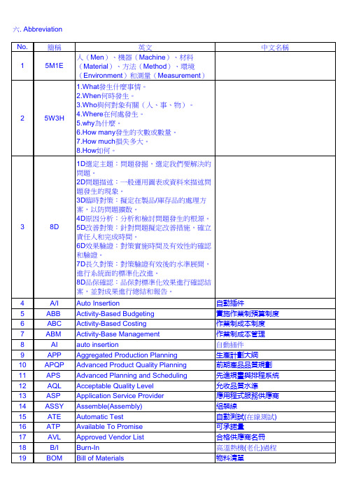

esp轧钢工艺流程英文回答:The ESP (Endless Strip Production) process is a continuous rolling process used in steelmaking to producehot-rolled coils without interruption. It is a highly efficient and automated method that offers numerous advantages over traditional batch rolling.The ESP process begins with the charging of a slab into the reheating furnace. The slab is heated to a high temperature, usually around 1,200 degrees Celsius, to makeit more malleable for the subsequent rolling process. Once heated, the slab is transferred to the roughing mill, where it undergoes a series of rolling passes to reduce its thickness and increase its length.After the roughing mill, the strip is transferred tothe finishing mill, where it undergoes further rolling passes to achieve the desired thickness and surface quality.The finishing mill is equipped with multiple stands that work in tandem to ensure precise control over the strip's dimensions.During the rolling process, the strip is cooled using water sprays or air jets to prevent overheating andmaintain its mechanical properties. The cooling processalso helps to improve the strip's surface quality by reducing the formation of scale.Once the rolling process is complete, the strip iscoiled at the coiler and then transferred to the downcoiler, where it is cooled further and prepared for further processing or shipment. The coiling and downcoiling processes are critical to ensure the strip's uniformity and prevent any defects.The ESP process offers several advantages overtraditional batch rolling. Firstly, it allows forcontinuous production without the need for frequent stops and starts, resulting in higher productivity and reduced production costs. Secondly, the continuous rolling processensures better dimensional control and surface quality ofthe strip. Lastly, the ESP process allows for theproduction of longer coils, which reduces the need for welding and improves the overall quality of the final product.Overall, the ESP process is a highly efficient and automated method for producing hot-rolled coils. Its continuous nature and precise control over the rolling parameters make it a preferred choice for many steel manufacturers.中文回答:ESP(无间断轧制)工艺是一种连续轧制工艺,用于生产热轧卷板而无需中断。

Product data sheetCharacteristicsXPSAK311144module XPSAK - Emergency stop - 24 V AC DCMainRange of productPreventa Safety automation Product or component type Preventa safety module Safety module name XPSAKSafety module application For emergency stop, switch, sensing mat/edges or safety light curtain monitoring Function of moduleProximity sensor monitoringEmergency stop monitoring 1-channel wiringMonitoring of electro-sensitive protection equipment (ESPE) Multiple emergency stop monitoring 2-channel wiring Monitoring of a movable guard Sensing mat and edges monitoringEmergency stop with 2 NC contacts monitoring 2-channel wiringMonitoring of a movable guard associated with 2 switches and automatic start Safety levelCan reach PL e/category 4 conforming to EN/ISO 13849-1 Can reach SILCL 3 conforming to EN/IEC 62061Safety reliability dataDC > 99 % conforming to EN/ISO 13849-1MTTFd = 154.5 years conforming to EN/ISO 13849-1 PFHd = 7.39E-9 1/h conforming to EN/IEC 62061Type of startConfigurableConnections - terminalsCaptive screw clamp terminals, 1 x 0.14...1 x 2.5 mm² flexible with ca-ble end, with double bezelCaptive screw clamp terminals, 1 x 0.14...1 x 2.5 mm² solid with cable end, with- double bezelCaptive screw clamp terminals, 1 x 0.25...1 x 1.5 mm² flexible with ca-ble end, with double bezelCaptive screw clamp terminals, 1 x 0.25...1 x 2.5 mm² flexible with ca-ble end, with double bezelCaptive screw clamp terminals, 2 x 0.14...2 x 0.75 mm² flexible with ca-ble end, with double bezelCaptive screw clamp terminals, 2 x 0.14...2 x 0.75 mm² solid with cable end, with- double bezelCaptive screw clamp terminals, 2 x 0.25...2 x 1 mm² flexible with cable end, with- double bezelCaptive screw clamp terminals, 2 x 0.5...2 x 1.5 mm² flexible with cable end, with- double bezelOutput typeRelay instantaneous opening, 3 NO circuit(s), volt-free Number of additional circuits 1 NC + 4 solid state outputs [Us] rated supply voltage24 V AC - 15...10 % 24 V DC - 15...10 %T h e i n f o r m a t i o n p r o v i d e d i n t h i s d o c u m e n t a t i o n c o n t a i n s g e n e r a l d e s c r i p t i o n s a n d /o r t e c h n i c a l c h a r a c t e r i s t i c s o f t h e p e r f o r m a n c e o f t h e p r o d u c t s c o n t a i n e d h e r e i n .T h i s d o c u m e n t a t i o n i s n o t i n t e n d e d a s a s u b s t i t u t e f o r a n d i s n o t t o b e u s e d f o r d e t e r m i n i n g s u i t a b i l i t y o r r e l i a b i l i t y o f t h e s e p r o d u c t s f o r s p e c i f i c u s e r a p p l i c a t i o n s .I t i s t h e d u t y o f a n y s u c h u s e r o r i n t e g r a t o r t o p e r f o r m t h e a p p r o p r i a t e a n d c o m p l e t e r i s k a n a l y s i s , e v a l u a t i o n a n d t e s t i n g o f t h e p r o d u c t s w i t h r e s p e c t t o t h e r e l e v a n t s p e c i f i c a p p l i c a t i o n o r u s e t h e r e o f .N e i t h e r S c h n e i d e r E l e c t r i c I n d u s t r i e s S A S n o r a n y o f i t s a f f i l i a t e s o r s u b s i d i a r i e s s h a l l b e r e s p o n s i b l e o r l i a b l e f o r m i s u s e o f t h e i n f o r m a t i o n c o n t a i n e d h e r e i n .ComplementarySynchronisation time between inputs Unlimited (manual start)2 or 4 s depending of wiring (automatic start)Supply frequency50/60 HzMaximum power consumption in VA5 VA ACInput protection type Internal, electronic[Uc] control circuit voltage24 V DCMaximum line resistance28 OhmBreaking capacity180 VA holding AC-15 C300 relay output1800 VA inrush AC-15 C300 relay outputBreaking capacity 1.5 A at 24 V (DC-13) time constant: 50 ms for relay outputOutput thermal current 6 A per relay for relay output[Ith] conventional free air thermal current18 AAssociated fuse rating4 A gG or gL for relay output conforming to EN/IEC 60947-5-1, DIN-VDE 0660 part 2006 A fast blow for relay output conforming to EN/IEC 60947-5-1, DIN-VDE 0660 part 200Minimum output current10 MA for relay outputMinimum output voltage17 V for relay outputMaximum response time on input open40 Ms[Ui] rated insulation voltage300 V (pollution degree 2) conforming to IEC 60947-5-1300 V (pollution degree 2) conforming to DIN VDE 0110 part 1[Uimp] rated impulse withstand voltage4 KV overvoltage category III conforming to IEC 60947-5-14 KV overvoltage category III conforming to DIN VDE 0110 part 1Local signalling 4 LEDsCurrent consumption30 mA at 24 V AC on power supplyMounting support35 mm symmetrical DIN railNet weight0.3 KgEnvironmentStandards EN/ISO 13850EN 1088/ISO 14119EN/IEC 60947-5-1EN/IEC 60204-1Product certifications CSAULTÜVIP degree of protection IP20 (terminals) conforming to EN/IEC 60529IP40 (enclosure) conforming to EN/IEC 60529Ambient air temperature for operation-10…55 °CAmbient air temperature for storage-25…85 °CPacking UnitsUnit Type of Package 1PCENumber of Units in Package 11Package 1 Weight354 GPackage 1 Height 6.5 CmPackage 1 width10.5 CmPackage 1 Length12.5 CmOffer SustainabilitySustainable offer status Green Premium productREACh Regulation REACh DeclarationEU RoHS Directive Pro-active compliance (Product out of EU RoHS legal scope)EU RoHS Decla-rationMercury free YesRoHS exemption information YesChina RoHS Regulation China RoHS DeclarationEnvironmental Disclosure Product Environmental ProfileCircularity Profile End Of Life InformationWEEE The product must be disposed on European Union markets following speci-fic waste collection and never end up in rubbish binsPVC free YesContractual warrantyWarranty18 monthsProduct data sheetXPSAK311144Dimensions DrawingsDimensionsProduct Life Status :End of commerc. announcedXPSAK311144 may be replaced by any of the following products:XPSUAK12APPreventa module Cat.4 features XPSUAF + PNP/NPN, safety mat 24vac/dc screwQty 1Reason for Substitution: End of life | Substitution date: 01 Jun 2019 |XPSUAK12APPreventa module Cat.4 features XPSUAF + PNP/NPN, safety mat 24vac/dc screwQty 1Reason for Substitution: End of life | Substitution date: 01 Jun 2019 |XPSUAK12APPreventa module Cat.4 features XPSUAF + PNP/NPN, safety mat 24vac/dc screwQty 1Reason for Substitution: End of life | Substitution date: 01 Jun 2019 |XPSUAK12APPreventa module Cat.4 features XPSUAF + PNP/NPN, safety mat 24vac/dc screwQty 1Reason for Substitution: End of life | Substitution date: 19 Feb 2020 |XPSUAK12APPreventa module Cat.4 features XPSUAF + PNP/NPN, safety mat 24vac/dc screwQty 1Reason for Substitution: End of life | Substitution date: 21 Aug 2020 |。

Installation InstructionsArmorPOINT RTD and Thermocouple Input ModulesCatalog numbers 1738-IR2M12, 1738-IT2IM12, Series A Table of ContentsTopic Page Important User Information2 Environment and Enclosure3 Preventing Electrostatic Discharge3About the Module4Mount the I/O Base5Install the Module6 Remove the Module from the Mounting Base6Wire the Module7 Communicate with the Module8 Interpret Status Indicators10 Specifications122 ArmorPOINT RTD and Thermocouple Input ModulesImportant User InformationSolid-state equipment has operational characteristics differing from those of electromechanical equipment. Safety Guidelines for the Application, Installation and Maintenance of Solid State Controls (Publication SGI-1.1 available from your local Rockwell Automation sales office or online at/literature/) describes some important differences betweensolid-state equipment and hard-wired electromechanical devices. Because of this difference, and also because of the wide variety of uses for solid-state equipment, all persons responsible for applying this equipment must satisfy themselves that each intended application of this equipment is acceptable.In no event will Rockwell Automation, Inc. be responsible or liable for indirect or consequential damages resulting from the use or application of this equipment.The examples and diagrams in this manual are included solely for illustrative purposes. Because of the many variables and requirements associated with any particular installation, Rockwell Automation, Inc. cannot assume responsibility or liability for actual use based on the examples and diagrams.No patent liability is assumed by Rockwell Automation, Inc. with respect to use of information, circuits, equipment, or software described in this manual.Reproduction of the contents of this manual, in whole or in part, without written permission of Rockwell Automation, Inc., is prohibited.Throughout this manual, when necessary, we use notes to make you aware of safety considerations.Publication 1738-IN005B-EN-E - January 2013ArmorPOINT RTD and Thermocouple Input Modules 3Publication 1738-IN005B-EN-E - January 2013Environment and EnclosurePreventing Electrostatic DischargeATTENTION: This equipment is intended for use in overvoltage Category II applications (as defined in IEC 60664-1), at altitudes up to 2000 m (6562 ft) without derating.This equipment is considered Group 1, Class A industrial equipment according to IEC/CISPR 11. Without appropriate precautions, there may be difficulties with electromagnetic compatibility in residential and other environments due to conducted and radiated disturbances.This equipment is supplied as enclosed equipment. It should not require additional system enclosure when used in locations consistent with theenclosure type ratings stated in the Specifications section of this publication. Subsequent sections of this publication may contain additional information regarding specific enclosure type ratings, beyond what this product provides, that are required to comply with certain product safety certifications.In addition to this publication, see:•Industrial Automation Wiring and Grounding Guidelines, RockwellAutomation publication 1770-4.1, for additional installation requirements.•NEMA Standard 250 and IEC 60529, as applicable, for explanations of thedegrees of protection provided by different types of enclosure.ATTENTION: This equipment is sensitive to electrostatic discharge, which can cause internal damage and affect normal operation. Follow these guidelines when you handle this equipment:•Touch a grounded object to discharge potential static.•Wear an approved grounding wriststrap.•Do not touch connectors or pins on component boards.•Do not touch circuit components inside the equipment.•Use a static-safe workstation, if available.•Store the equipment in appropriate static-safe packaging when not in use.4 ArmorPOINT RTD and Thermocouple Input ModulesPublication 1738-IN005B-EN-E - January 2013About the ModuleThe ArmorPOINT™ I/O family consists of modular I/O modules. The sealed IP67 housing of these modules requires no enclosure. Note that environmental requirements other than IP67 may require an additional appropriate housing. I/O connectors are sealed M12 (micro) style. The mounting base ships with the module. The 1738-IR2M12 module is shown here.ArmorPOINT RTD and Thermocouple Input ModuleDescriptionDescription1Connector M12-A 3LED indicators2Connector M12-B3ArmorPOINT RTD and Thermocouple Input Modules 5Publication 1738-IN005B-EN-E - January 2013Mount the I/O BaseMount the I/O base on a wall or panel, using the screw holes provided in the base.Mounting Diagram for ArmorPOINT Base with AdapterFollow the instructions to install the mounting base.y out the required points as shown above in the drilling dimension diagram.2.Drill the necessary holes for M4 (#8) machine or self-tapping screws.3.Mount the base using M4 (#8) screws.4.Ground the system using the ground lug connection. The ground lug connectionis also a mounting hole.Mounting BaseIMPORTANTThe module must be mounted on a grounded metal mounting plate or otherconductive surface.KeyswitchGround lug connectionLatching mechanism6 ArmorPOINT RTD and Thermocouple Input ModulesInstall the ModuleFollow the instructions to install the ArmorPOINT input module.ing a bladed screwdriver, rotate the keyswitch on the mounting base clockwiseuntil the number 6 aligns with the notch in the base.2.Position the module vertically above the mounting base. The module bridgestwo bases.3.Push the module down until it engages the latching mechanism. Y ou hear aclicking sound when the module is properly engaged. The locking mechanismlocks the module to the base.Remove the Module from the Mounting BaseFollow the instructions to remove the module from the mounting base.1.Insert a flat blade screwdriver into the slot of the orange latching mechanism.2.Push the screwdriver toward the I/O module to disengage the latch. The modulelifts up off the base.3.Pull the module off the base.Publication 1738-IN005B-EN-E - January 2013ArmorPOINT RTD and Thermocouple Input Modules 7Publication 1738-IN005B-EN-E - January 2013Wire the ModuleFollow the wiring instructions for the ArmorPOINT input modules.1738-IR2M121738-IT2IM12IMPORTANTAnalog modules have earth grounded metal rings. This should be considered when choosing shielded cables and grounding techniques.ATTENTION: Make sure all connectors and caps are securely tightened to properly seal the connections against leaks and maintain IP67 requirements.(View into connector) Pin 1 No connectPin 2 Input 0A (M12-A)Input 1A (M12-B) Pin 3 Input 0C (M12-A)Input 1C (M12-B) Pin 4 Input 0B (M12-A)Input 1B (M12-B) Pin 5 No connect(View into connector) Pin 1 CJC +Pin 2 TC 0 + (M12-A)TC 1 + (M12-B) Pin 3 CJC -Pin 4 TC 0 - (M12-A)TC 1 - (M12-B) Pin 5 No connect8 ArmorPOINT RTD and Thermocouple Input ModulesPublication 1738-IN005B-EN-E - January 2013Communicate with the ModuleI/O messages are sent to (consumed) and received from (produced) the ArmorPOINT I/O modules. These messages are mapped onto the processor’s memory. TheArmorPOINT RTD I/O input module produces 6 Bytes of input data (scanner Rx – status) and fault status data. The ArmorPOINT thermocouple I/O input module produces 8 Bytes of input data (scanner Rx – status) and fault status data. They do not consume I/O data (scanner Tx).Default Data Map – 1738-IR2M12Message size: 6 Bytes15141312111009080706050403020100Produces (scanner Rx)Input channel 0 high byte Input channel 0 low byte Input channel 1 high byteInput channel 1 low byte Status byte for channel 1Status byte for channel 0ORURHHA LLA HA LACM CFORURHHA LLA HA LACM CFConsumes (scanner Tx)No consumed data Where:OR = Overrange; 0 = No error, 1 = Fault UR = Underrange; 0 = No error, 1 = FaultHHA = High/High Alarm; 0 = No error, 1 = Fault LLA = Low/Low Alarm; 0 = No error, 1 = Fault HA = High Alarm; 0 = No error, 1 = Fault LA = Low Alarm; 0 = No error, 1 = FaultCM = Calibration Mode; 0 = Normal, 1 = Calibration mode CF = Channel Fault Status; 0 = No error, 1 = FaultArmorPOINT RTD and Thermocouple Input Modules 9Publication 1738-IN005B-EN-E - January 2013Default Data Map – 1738-IT2IM12Message size: 6 Bytes15141312111009080706050403020100Produces (scanner Rx)Input channel 0 high byte Input channel 0 low byte Input channel 1 high byteInput channel 1 low byte Status byte for channel 1Status byte for channel 0OR UR HHA LLA HA LACM CFORURHHA LLA HA LACM CFORURCold junction temperature(Selectable channel 0, channel 1, or average of both channels 0 and 1)Consumes (scanner Tx)No consumed data Where:OR = Overrange; 0 = No error, 1 = Fault UR = Underrange; 0 = No error, 1 = FaultHHA = High/High Alarm; 0 = No error, 1 = Fault LLA = Low/Low Alarm; 0 = No error, 1 = Fault HA = High Alarm; 0 = No error, 1 = Fault LA = Low Alarm; 0 = No error, 1 = FaultCM = Calibration Mode; 0 = Normal, 1 = Calibration mode CF = Channel Fault Status; 0 = No error, 1 = Fault10 ArmorPOINT RTD and Thermocouple Input ModulesPublication 1738-IN005B-EN-E - January 2013Interpret Status IndicatorsThis module has the following indicators:•Adapter, DeviceNet and POINTBus status indicators •System and Adapter power indicators•Individual I/O status indicators for inputs and outputsIndicator Status for ModulesStatusDescriptionModule statusOff No power applied to device.Green Device operating normally.Flashing green Device needs commissioning due to missing, incomplete, or incorrect configuration.Flashing red Recoverable fault.RedUnrecoverable fault – may require device replacement.Flashing red/green Device is in self-test.I/O status indicatorNetwork status indicatorModule status indicator 1738-IR2M12ArmorPOINT RTD and Thermocouple Input Modules 11Publication 1738-IN005B-EN-E - January 2013Network status OffDevice is not online:- Device has not completed dup_MAC-id test.- Device not powered – check module status indicator.Flashing green Device is online but has no connections in the established state.Green Device is online and has connections in the established state.Flashing red One or more I/O connections are in timed-out state.RedCritical link failure – failed communication device. Device detected error that prevents it from communicating on the network. Possible duplicate MAC ID or baud rate mismatch.Flashing red/green Communication faulted device – the device has detected anetwork access error and is in communication faulted state. Device has received and accepted an Identity Communication Faulted Request – long protocol message.I/O statusOff Module in CAL mode.Solid green Normal (channel scanning inputs).Flashing green Channel being calibrated.Solid red Major channel fault.Flashing redChannel at end of range (over or under).Indicator Status for ModulesStatusDescription12 ArmorPOINT RTD and Thermocouple Input ModulesPublication 1738-IN005B-EN-E - January 2013SpecificationsArmorPOINT RTD and Thermocouple Input Modules – 1738-IR2M12, 1738-IT2IM12AttributeValueInputs per module 1738-IR2M12 – 2 single-ended, nonisolated1738-IT2IM12 – 2 differential, individually isolatedResolution1738-IR2M12 – 16 bits, 9.5 mV/cnt, 0.03 °C/cnt (Pt385 @ 25 °) 1738-IT2IM12 – 15 bits plus sign, 2.5 mV/cnt Thermocouple type (and resolution average over span)1738-IT2IM12 only Sensor Range Resolution (average over span)Type B 30…1820 °C 3 counts/°C Type C 0…2315 °C 6 counts/°C Type E -270…1000 °C 24 counts/°C Type J -210…1200 °C 21 counts/°C Type K -270…1372 °C 13 counts/°C Type N -270…1300 °C 11 counts/°C Type R -50…1768.1 °C 4 counts/°C Type S -50…1768.1 °C 4 counts/°C Type T-270…400 °C15 counts/°CRTD sensors supported1738-IR2M12 only100 Ω Pt α = 0.00385 Euro (-200…870 °C) 200 Ω Pt α = 0.00385 Euro (-200…630 °C) 100 Ω Pt α = 0.003916 U.S. (-200…630 °C) 200 Ω Pt α = 0.003916 U.S. (-200…630 °C) 10 Ω Cu α = 0.00427 (-200…260 °C) 100 Ω Ni α = 0.00618 (-60…250 °C) 120 Ω Ni α = 0.00672 (-60…250 °C) 120 Ω Ni α = 0.00618 (-60…250 °C)Cold junctioncompensation range 1738-IT2IM12 – 0…70 °C Input range 1738-IR2M12 – 0…600 Ω 1738-IT2IM12 – ±75 mV Absolute accuracy (1)0.1% full scale @ 25 °C Accuracy drift w/temp30 ppm/°CArmorPOINT RTD and Thermocouple Input Modules 13Publication 1738-IN005B-EN-E - January 2013Input update rate (per module)1738-IR2M1240 ms @ Notch = 50 Hz33 ms @ Notch = 60 Hz (default) 20 ms @ Notch = 100 Hz 17 ms @ Notch = 120 Hz 10 ms @ Notch = 200 Hz 8 ms @ Notch = 240 Hz 7 ms @ Notch = 300 Hz 5 ms @ Notch = 400 Hz 4 ms @ Notch = 480 Hz 1738-IT2IM1220 ms @ Notch = 50 Hz17 ms @ Notch = 60 Hz (default) 10 ms @ Notch = 100 Hz 8 ms @ Notch = 120 Hz 5 ms @ Notch = 200 Hz 4 ms @ Notch = 240 Hz 3 ms @ Notch = 300 Hz 3 ms @ Notch = 400 Hz 2 ms @ Notch = 480 HzStep response (per channel)60 ms @ Notch = 50 Hz 50 ms @ Notch = 60 Hz 30 ms @ Notch = 100 Hz 25 ms @ Notch = 120 Hz 15 ms @ Notch = 200 Hz 13 ms @ Notch = 240 Hz 10 ms @ Notch = 300 Hz 8 ms @ Notch = 400 Hz 6 ms @ Notch = 480 Hz Input resistance 1738-IT2IM12 only – 1 M ΩInput impedance 1738-IT2IM12 only – 100 K ΩConversion typeDelta Sigma Common mode rejection ratio 120 dBNormal mode rejection ratio100 dB -3 dbNotch filter13.1 Hz @ Notch = 50 Hz 15.7 Hz @ Notch = 60 Hz 26.2 Hz @ Notch = 100 Hz 31.4 Hz @ Notch = 120 Hz 52.4 Hz @ Notch = 200 Hz 62.9 Hz @ Notch = 240 Hz 78.6 Hz @ Notch = 300 Hz 104.8 Hz @ Notch = 400 Hz 125.7 Hz @ Notch = 380 Hz Data format Signed integerMaximum overload1738-IR2M12 – No input protection1738-IT2IM12 – Input not overvoltage protected(1)Includes offset, gain, non-linearity and repeatability error termsArmorPOINT RTD and Thermocouple Input Modules – 1738-IR2M12, 1738-IT2IM12AttributeValue14 ArmorPOINT RTD and Thermocouple Input Modules Publication 1738-IN005B-EN-E - January 2013General SpecificationsAttributeValueMounting base screw torque M4 (#8) screw,0.85 Nm (7.5 lb-in.) in aluminum, 1.8 Nm (16 lb-in.) in steel Calibration Factory-calibratedPOINTBus current 1738-IR2 – 220 mA @ 5V DC 1738-IT2I – 175 mA @ 5V DC Power dissipation, max 1.0 W Thermal dissipation, max 3.3 BTU/hrIsolation voltage Tested at 50V rms (1738-IT2I has isolation between individual channels)Dielectric test 1000V rms flash for 1s External DC power No external power requiredLED indicators1 green/red – module status indicator, logic side 1 green/red – network status indicator, logic side2 green/red – input status indicators, logic side Dimensions, HxWxD 31.75 x 66.80 x 107.95 mm (1.25 x 2.63 x 4.25 in.)Weight0.289 kg (0.637 lb)Enclosure type rating Meets IP65/66/67 (when marked)Wiring category (1) 1 – on signal ports Keyswitch position6(1)Use this Conductor Category information for planning conductor routing. Refer to Industrial Automation Wiring and Grounding Guidelines, publication 1770-4.1.Environmental SpecificationsAttributeValueTemperature, operatingIEC 60068-2-1 (Test Ad, Operating Cold), IEC 60068-2-2 (Test Bd, Operating Dry Heat),IEC 60068-2-14 (Test Nb, Operating Thermal Shock): -20…60 °C (-4…140 °F)Temperature, storageIEC 60068-2-1 (Test Ab, Unpackaged Nonoperating Cold), IEC 60068-2-2 (Test Bb, Unpackaged Nonoperating Dry Heat), -40…85 °C (-40…185 °F)Relative humidityIEC 60068-2-30 (Test Db, Unpackaged Nonoperating Damp Heat): 5…95% noncondensingArmorPOINT RTD and Thermocouple Input Modules 15Publication 1738-IN005B-EN-E - January 2013Vibration IEC60068-2-6 (Test Fc, Operating): 5 g @ 10…500 HzShock, operating IEC60068-2-27 (Test Ea, Unpackaged Shock): 30 gShock, nonoperating IEC60068-2-27 (Test Ea, Unpackaged Shock): 50 gEmissions Emissions CSPR 11: Group 1, Class A ESD immunityIEC 61000-4-2:6 kV contact discharges 8 kV air dischargesRadiated RF immunityIEC 61000-4-3:10V/m with 1 kHz sine-wave 80% AM @ 30 MHz…1000 MHz 10V/m with 200 Hz 50% pulse 100% AM @ 900 Mhz EFT/B immunity IEC 61000-4-4:±3 kV @ 5 kHz on signal ports Surge transient immunity IEC 61000-4-5:±2 kV line-earth(CM) on shielded portsConducted RF immunityIEC 61000-4-6:10Vrms with 1kHz sine-wave 80% AM @ 150 kHz…80 MHzCertificationsCertification (when product is marked)(1)Valuec-UL-us UL-listed Industrial Control Equipment, certified for US and Canada CEEuropean Union 89/336/EEC EMC Directive, compliant with: EN 61000-6-4; Industrial Emissions EN 50082-2; Industrial ImmunityEN 61326; Meas./Control/Lab., Industrial Requirements EN 61000-6-2; Industrial Immunity C-TickAustralian Radiocommunications Act, compliant with: AS/NZS CISPR 11; Industrial Emissions(1)See the Product Certification link at for Declaration of Conformity, Certificates, and other certification details.Environmental SpecificationsAttributeValueRockwell Automation SupportRockwell Automation provides technical information on the Web to assist you in using its products. At /support/, you can find technical manuals, a knowledge base of FAQs, technical and application notes, sample code and links to software service packs, and a MySupport feature that you can customize to make the best use of these tools.For an additional level of technical phone support for installation, configuration and troubleshooting, we offer TechConnect support programs. For more information, contact your local distributor or Rockwell Automation representative, or visit /support/.Installation AssistanceIf you experience a problem within the first 24 hours of installation, please review the information that's contained in this manual. You can also contact a special Customer Support number for initial help in getting your product up and running.New Product Satisfaction ReturnRockwell Automation tests all of its products to ensure that they are fully operational when shipped from the manufacturing facility. However, if your product is not functioning and needs to be returned, follow these procedures.Documentation FeedbackYour comments will help us serve your documentation needs better. If you have any suggestions on how to improve this document, complete this form, publication RA-DU002, available at /literature/.United States or Canada 1.440.646.3434Outside United States or CanadaUse the Worldwide Locator at/support/americas/phone_en.html , or contact your local Rockwell Automation representative.United StatesContact your distributor. You must provide a Customer Support case number (call the phone number above to obtain one) to your distributor to complete the return process.Outside United StatesPlease contact your local Rockwell Automation representative for the return procedure.Publication 1738-IN005B-EN-E - January 2013Supersedes Publication 1738-IN005A-EN-E - June 2004Copyright © 2013 Rockwell Automation, Inc. All rights reserved.Allen-Bradley, Rockwell Automation, ArmorPOINT, and T echConnect are trademarks of Rockwell Automation, Inc.Trademarks not belonging to Rockwell Automation are property of their respective companies.。

1w w w.n o i s e k e n.c o mThe electrostatic simulator you always use is renewed now. The new main unit and discharge gun in sale now are `ESS-S3011A`, ` ESS-B3011A` and `GT-30RA`.For repair maintenance in our company, we discontinue repair support 8 years after delivery according to warranty and 5 years after sales termination. For those electrostatic simulators whose repair support is terminated, we may decline to repair. For discharge gun 'TC-815 series', as there are many discontinued parts, it is difficult to continue to support it. We plan to terminate the repair support as the following schedule.ESD SimulatorESS-S3011A & GT-30RASmart model equipped high function & extendibilityInformation on successive model (current model)Repair support termination schedule:discharge gunModelRepair service and support statussuccessive modelTC-815C terminated GT-30RA TC-815D terminated GT-30RA TC-815D(F)terminated GT-30RA TC-815P terminated GT-30RA TC-815R terminatedGT-30RA TC-815RE22020年(scheduled)GT-30RA TC-815S2020年(scheduled)GT-30RA TC-815-330/2K2020年(scheduled)GT-30R3302KA※Old standard:IEC61000-4-2 Ed1 compliant (new standard incompliant)Repair support termination schedule noticeModelRepair service and support status successive modelESS-630 series terminated ESS-B3011A ESS-200AX terminated ESS-S3011A ESS-100L terminated ESS-B3011A ESS-100LA terminated ESS-B3011A ESS-2000terminated ESS-S3011A ESS-2002terminated ESS-B3011A ESS-2000AX terminated ESS-S3011A ESS-2002EXterminatedESS-B3011AFor the customers who above have electrostatic simulators and discharge gun, please consider to buy the successive model(current model) as replacement.ESS-630A ESS-200AX ESS-100L ESS-2000ESS-2002ESS-2000AX/2002EXEMC test equipment to evaluate the resistibility of electronic equipments when en-ergy charged on a human body or object is discharged to the electronic equipment.This can be available for evaluating malfunctions or functions declines of electronic equipment against the ESD.Programmable simulator to ease some complicated tests. The output voltage is up to 30kV and performable IEC61000-4-2 & ISO 10605 Standardscompliant tests.●“3 pre-checking function” to make sure the more confirmable test ●“CR constant indicator” to make sure the correct unit attachment ●One-touch exchange of gun head and CR unit realized ●“Ten-key & Rotary knob” to ease the setting.●“Discharge Detecting Function” to realize the air-discharge confirmation.●“Lightest discharge gun in the market” to lighten the continuous operation (Excluding the cable and connector)●“White LED Irradiator” to facilitate the visualization of the discharging areas.●“ Control Software” to enable the test result reporting and control with PC.Provided by:Advanced Test Equipment Corp .® (800) 404-ATECRentals • Sales • Calibration • ServiceESD SimulatorESS-B3011A & GT-30RACost-oriented basic model ESD Simulator the light weight discharge gun attach-able.The output voltage can be selected either max. 30kV (B3011A) or max.16kV (L1611A) and compliant to both EN/IEC61000-4-2 Standard (both B3011A and L1611A) and ISO10605 Standard (only B3011A).Cost-oriented Basic modelsESS-S3011A & GT-30RAParameter Specification Polarity Positive / Negative Output voltage 0.20kV ~ 30.0kV±5% (30.5kVmax) ~10.0kV : 0.01kV step ~30.0kV : 0.1kV step Repetition cycle 0.05s ~ 600s±10% / Manual Set step : 0.01s (0.05 ~ 9.99s), 0.10s (10.0 ~ 600.0s)No. of time of discharge 1~60,000 times, Preset 1 time step or continuous preset Discharge mode Contact discharge / Air discharge Radiation level mode NORMAL mode / EXTRA mode Trigger mode Gun trigger / Main trigger / External trigger Operation panel Color LCD / Push-buttons (Partially lighting)Gun holder Standard attached (to hold the discharge gun Model GT-30RA)Radiation mode select switch Extra / Normal switching function built-inDischarge detection Discharge detection function in air-discharge equipped Pre-checking function Following 3 steps function equipped (by user operation. Not the calibration but just checking) SETP1 : High voltage output checking STEP2 : Withstanding voltage checking STEP3 : Discharge relay operation checking CR & Gun head checking CR constant and gun head recognizable (with an indicator to prevent the wrong combination)Parameter Specification"IEC STANDARD" Contact discharge mode : 2.0kV, 4.0kV, 6.0kV and 8.0kV step test mode Air discharge mode : 2.0kV, 4.0kV, 8.0kV and 15.0kV step "MANUAL" Contact / Air discharge mode, Arbitrary setting during 0.2kV~30.0kV test mode Sweeping function built-in, Recordable up to 99 units "SEQUENCE" Enables to operate units set in MANUAL mode continuously.test mode Max. 22 steps / 1 program and the programs recordable up to 20.Warning lamp Lighting at voltage output from the generator. Blinking at electro-static dischargingCharge capacitor / resistor 150pF±10%, 330Ω±10%(Built-in CR unit for discharge gun GT-30RA)Charge resistor in generator 10MΩ(Totally 53Ω in combination with 43MΩ in discharge gun)*AUX connector D-SUB 15pins female connector (for connecting to patolight, automated ESD eliminator, external interlock input, external trigger input terminal)Optical communication Optical connector (serial interface) for connecting to PC connector Power supply / consumption AC100V~AC240V 50Hz / 60Hz ±10% 75VA Dimension Generator : (W)392mm X (H)312mm X (D)295.3mm (including gun holder) Discharge gun : (W)83.3mm X (H)217.2mm X (D)229.3mm Mass Generator : Approx. 7.5kg Discharge gun : Approx. 800g (excluding cable and connector)* The constant depends on combination with CR unit for the discharge gun● “Pre-checking function” taking the confirmable test into the account ● “Discharge Detecting Function” to realize the air-discharge confirmation.● “Lightest Discharge Gun in the market” to lighten the continual operation"● “White LED Irradiator” to facilitate the visualization of the discharging area.● “CR constant checking function” (No indicator) to make the correct unit attachment sure"● One-touch exchange of gun head and CR unit realizedParameter Specification Output voltage 0.20kV~30.0kV±5%(30.5kVmax) ESS-L1611A is 16kVmax Polarity Positive / Negative Repetition cycle 0.05s~9.99s±10%, 0.01s step / ManualNo. of time of discharge 1~999 times, Preset 1 time step or continuous preset Discharge mode Contact discharge / Air discharge Trigger mode Gun trigger / Main trigger Operation panel Indicator : 5X7 Dot matrix LED / Operation : Push buttons Radiation mode select switch Extra / Normal switching function built-inDischarge detection Discharge detection function in air-discharge equipped.Pre-checking function High voltage output checking function (by user operation. Not the calibration but just checking)CR & Gun head CR constant and gun head recognizable checking (to prevent the wrong combination without indicator)IEC LEVELContact discharge mode : 2.0kV, 4.0kV, 6.0kV and 8.0kV step Switching function Air discharge mode : 2.0kV, 4.0kV, 8.0kV and 15.0kV step)Parameter SpecificationWarning lamp Lighting at voltage output from the generator. Blinking at electro-static discharging Charge capacitor / resistor 150pF±10%, 330Ω±10% (Built-in CR unit for discharge gun GT-30RA)Charge resistor in generator 10MΩ (Totally 53Ω in combination with 43MΩ in discharge gun)*Power supply / consumption AC100V~AC240V ±10% 50Hz / 60Hz 62VA Dimension Generator : (W)270 X (H)263 X (D)200mm Discharge gun : (W)83.3 X (H)217.2 X (D)229.3mm Mass Generator : Approx. 4.8kg Discharge gun : Approx. 800g (excluding cable and connector)* Remote control function not built-in.* The constant depends on combination with CR unit for the discharge gun。

Product featuresTVSATransient voltage ESD suppressor•Lead free, halogen free and RoHS compliant forglobal applications•Single-line, bi-directional device for placement flexibility•Silicon based chip•Low capacitance to meet the needs for high speed single transient voltage protection•Provides ESD protection with fast response time (<1ns) allowing equipment to pass IEC 61000-4-2level 4 test•Low profile designs for board space savings•Low leakage current reduces power consumption •Low clamping voltage•Solid-state silicon-avalanche technologyPbApplications•Computers and peripherals •Digital cameras •Mobile phones •DVD/Media Players•MP3/Multimedia players •A-V Equipment •External storage •DSL Modems •Set top boxes •Docking systemsV18C001Product Family SizeWorking DC Voltage Capacitance in pF** Part numbers use “R” to denote decimal point for decimal values of pico farads.TVSA 04Packaging•Size 0201: 15,000 pieces per reel - EIA (EIAJ)•Size 0402: 10,000 pieces per reel - EIA (EIAJ)Surface Mount Device 12EatonElectronics Division 1000 Eaton Boulevard Cleveland, OH 44122United States/electronics© 2017 EatonAll Rights Reserved Printed in USA Publication No. DS 4072 BU-SB13279 June 2017Eaton is a registered trademark.All other trademarks are property of their respective owners.Life Support Policy: Eaton does not authorize the use of any of its products for use in life support devices or systems without the express written approval of an officer of the Company. Life support systems are devices which support or sustain life, and whose failure to perform, when properly used in accordance with instructions for use provided in the labeling, can be reasonably expected to result in significant injury to the user.Eaton reserves the right, without notice, to change design or construction of any products and to discontinue or limit distribution of any products. Eaton also reserves the right to change or update, without notice, any technical information contained in this bulletin.Technical Data DS4072Effective June 2017TVSATransient voltage ESD suppressorDimensions - mmWHLC Size LW H C 02010.60±0.050.30±0.050.30±0.050.20±0.100402 1.00±0.150.50±0.100.50±0.100.25±0.15Recommended Pad Layout - mm (in)Size b a c d 02010.230.300.450.83(0.009)(0.012)(0.018)(0.033)04020.510.610.51 1.70(0.020)(0.024)(0.020)(0.067)Tape Packaging Specifications - mmTime (seconds)T e m p e r a t u r e (°C )Soldering Recommendations•Compatible with lead and lead-free solder reflow processes •Peak reflow temperatures and durations:-IR Reflow = 260°C max for 30 sec. max.-Wave Solder = 260°C max. for 10 sec. max.•Recommended IR Reflow Profile:。

The GUIDE MWD surface system is a complete, field-proven wellsitesolution. The GUIDE system is the most compact and portable sur-face system available, enabling setup times of less than 20 minutes.Powerful and intuitive software drives optimized decoding and wellarchiving, and a customizable main screen and automated WITScapability ensure ease of use. Two configurable while-drilling se-quences, in addition to the survey sequence, let the user determineexactly what needs to be displayed; in addition, automatic switchingbetween sequences eliminates the concern of receiving the wronginformation.The complete GUIDE MWD surface system includes the following:• Rig floor decoder• Surface system interface• MWD decoder software• MWD desktop software for PC• Pressure transducer (10,000 psi, 4 to 20 mA, hammer union)• Two antennas with magnetic mounts• Pressure transducer cable• Tool interface cable• Weather-proof Pelican TM case• Laptop computer (optional)The GUIDE system displays real-time shock, vibration, and RPMon the main screen, and lower bandwidth warnings or ranges canalso be set up. Automated intelligent matrix filtering ensures thatthe GUIDE system receives the most data per pulse, with optimizeddecoding increasing the quality of the data. Two antennas providefreedom in placing the rig floor decoder, which typically would behindered by cables. The GUIDE system eliminates the need to enterparameters, with the system selecting the best configuration andtransferring WITS data in seconds. The surface system interfacefeatures an array of cable ports to enhance flexibility, includinga transducer cable for pulse simulations, tool interface cable fordirect tool communication, rugged N-type connector for wirelesscommunication to the rig floor decoder, and a standard USB to connect to a PC.***********©2016 National Oilwell Varco. All rights reserved. NOV-DDS-F-1503-001 Dynamic Drilling Solutions | InTerra™ Sensors and SystemsTool Specification。
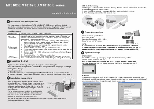
Installation and Startup GuideThis document covers the installation of MT8102iE/iEU/MT8103iE Series HMI, for the detailedspecifications and operation, please refer to Datasheet, Brochure and EasyBuilder Pro User Manual. Please read all warnings, precautions, and instructions on the device carefully before use.Install Environment: NEMA Rating The HMI product is NEMA 4 rated (Indoor Only).Electrical EnvironmentThe HMI product has been tested to conform to European CE requirements. This means that the circuitry is designed to resist the effects of electrical noise. This does not guarantee noise immunity in severe cases. Proper wire routing and grounding will insure proper operation.Environmental Considerations(1) Make sure that the displays are installed correctly and that the operatinglimits are followed. Avoid installing units in environments where severe mechanical vibration or shocks are present.(2) Do not operate the unit in areas subject to explosion hazards due toflammable gases, vapors or dusts.(3) Do not install the unit where acid gas, such as SO2 exists.(4) This device should be mounted in the vertical position and for use on the flatsurface enclosure.(5) Conform to UL 61010-2-201 safety requirement for use in Pollution Degree2 Environment.(6) Relative Humidity: 10% ~ 90% (non-condensing)CleaningConsiderationsDisconnect this device from AC outlet before cleaning. Clean the device using cloths wetted with clean water. Do not use liquid or spray detergents for cleaning.Unpacking the UnitUnpack and check the delivery. If damage is found, please contact the supplier.NOTE: Place the operator panel on a stable surface during installation. Dropping it or letting it fall may cause damage. The package includes:(1) Installation Instruction, 2-sided A4 *1 (2) Human Machine Interface *1 (3) Power Connector *1(4) Brackets & Screws *1 pack (5) Fuse 1.25A/250V 5*20mm *1 (6) USB Stick Clamp & Tying Strap *1Installation InstructionsUse a control box that provides enough stiffness. Cutout Dimension: 260 mm x 202 mm. Secure the operator panel in position, using all the fastening holes and the provided brackets and screws. Screw Torque: 2.6 ~ 3.9 lbf.in. (For reaching waterproof effect and preventing the panel from being deformed.)Plan for adequate space around the unit and inside the enclosure, for ventilation and cables. Consider the heat from other devices inside the enclosure. The ambient temperature around the unit must be 0 ~ 50°CMinimum required clearances (along the overlay): Top 15 mm / Bottom 50 mm / Sides 15 mm Maximum panel thickness: 4.5 mmUSB Stick Clamp UsageCombining the USB Stick with the clamp and the tying strap can prevent USB stick from disconnecting with HMI when strong vibration is present.1. Insert the USB connector to the clamp and tie them together with the tying strap.2. Press the spring and insert the USB stick into HMI.Power ConnectionsPower Connector Specifications: Wire AWG: 28~12Operating Temperature: -40°C ~105°C Screw Torque: 3.47 lbf-in (max.)NOTE:1. Co nnect positive DC line to the ‘+’ terminal and the DC ground to the ‘-’ terminal.2. When downloading project using a USB cable, do not connect HMI with PLC and PC simultaneously , for electric potential difference may result in damage to HMI or PC.System SettingsMT8102iE/iEUWhen HMI is powered up and displays image, click the system setting button. (Default System Password: 111111)Note: It is necessary to connect the HMI to your network through a RJ-45 cable. Go to the Network tab, you may choose to auto get DHCP IP , or designate your own IP .MT8103iEThe settings are almost the same as MT8102iE/iEU. MT8103iE supports Wi-Fi. To use Wi-Fi, go to Wireless tab, tap Wi-Fi setting button to open the settings dialog box, in which you can turn Wi-Fi on/off, choose a network, and see the signal strength of each access point.MT8102iE MT8102iEU MT8103iE series Installation Instruction3 54 1 2EasyBuilder Pro Software SettingsLaunch EasyBuilder Pro software, select your project file, press F7 shortcut key to open the downloaddialog box: Select Ethernet > IP tab > Enter your HMI IP > Click Download to download this projectfile to HMI. Using screensaver and backlight saver is recommended in order to avoid imagepersistence caused by displaying the same image on HMI for a long time.( Please refer to EasyBuilder Pro User Manual for software operation details. )Communication ConnectionsNOTE:1. COM1 /COM2 / COM3 RS485 2W support MPI 187.5K, please use one at a time.2. Only Tx & Rx (no RTS/CTS) may be used for COM1 RS232 when COM3 RS232 is also used.3. COM3 RS485 4W will not be available when COM1 RS485 2W is used.Con.B Con.ACOM1 / COM2 / COM3 [RS485] 9 Pin, Female, D-subJumper SettingsBattery ReplacementBattery replacement shall be performed by qualified personnel only and care must be taken whenhandling lithium batteries. For more information on battery replacement and disposal considerations,please refer to the following link:/download/MT8000/eng/FAQ/FAQ_103_Replace_Battery_en.pdfNOTE: Make sure that all local and national electrical standards are met wheninstalling the unit. Contact your local authorities to determine which codes apply.PowerUse power output that meets SELV (Safety Extra-Low Voltage) requirements. The unit can bepowered by DC power only, voltage range: 24±20%, compatible with most controller DCsystems. The power conditioning circuitry inside the unit is accomplished by a switching powersupply. The peak starting current can be as high as 2A.Fusing Require-mentsFuse min. rating: 1.25A/250V. Use the fuse only in DC circuit. If the display does not come onwithin 5 seconds of power up, remove power. An internal fuse will prevent damage if the polarityof the DC power is incorrect. Check wiring for proper connections and try to power up again.Replacing fuse shall be performed by qualified personnel only. For more information, see:/download/MT8000/eng/FAQ/FAQ_104_Replace_Fuse_en.pdfHigh VoltageAn Internal fuse will prevent damage for overcurrent condition however it isn’t guaranteed. DCvoltage sources should provide proper isolation from main AC power and similar hazards.Emergency Stop A Hard-wired EMERGENCY STOP should be fitted in any system using an HMI to comply withICS Safety Recommendations.Supply VoltageConditionDo not power the unit and inductive DC loads, or input circuitry to the controller, with the samepower supply. Note: The 24 VDC output from some controllers may not have enough current topower the unit.Wire Routinga. Power wire length should be minimized (Max: 500m shielded, 300m unshielded).b. Please use twisted pair cables for power wire and signal wire and conform to theimpedance matching.c. If wiring is to be exposed to lightning or surges, use appropriate surge suppressiondevices.d. Keep AC, high energy, and rapidly switching DC power wiring separated from signal wires.e. Add a resistor and capacitor in the parallel connection between the ungrounded DC powersupply and the frame ground. This provides a path for static and high frequencydissipation. Typical values to use are 1M Ohm and 4700pF.HardwareConsiderationsThe system designer should be aware that devices in Controller systems could fail andthereby create an unsafe condition. Furthermore, electrical interference in an operatorinterface can lead to equipment start-up, which could result in property damage and/orphysical injury to the operator.If you use any programmable control systems that require an operator, be aware that thispotential safety hazard exists and take appropriate precautions. Although the specific designsteps depend on your particular application, the following precautions generally apply toinstallation of solid-state programmable control devices, and conform to the guidelines forinstallation of Controllers recommended in NEMA ICS 3-304 Control Standards.ProgrammingConsiderationsTo conform to ICS Safety Recommendations, checks should be placed in the controller toensure that all writable registers that control critical parts of plant or machinery have limitchecks built into the program, with an out-of-limit safe shut down procedure to ensure safety ofpersonnel.GME8A23E1_MT8102iE1_8102iEU_8103iE1_V1.3_Installation_180705DANGERCAUTIONLimited WarrantyThis product is limited warranted against defects in design and manufacture.The proven defective product will either be repaired or replaced, at Weintek’s discretion.This warranty shall not cover any product which is(a) Out of warranty period which is 12 months from the manufacturing month of the HMI products.(b) Damage caused by Force Majeure, accident, negligence, improper installation or misuse.(c) Product has been repaired or taken apart by unauthorized technicians.(d) Products whose identification markings have been removed or damaged.6789PIN#COM1[RS232]COM3[RS232]12 RxD3 TxD45 GND67 RTS TxD8 CTS RxD9 GNDPIN#COM1[RS485]2WCOM2[RS485]2WCOM2[RS485]4WCOM3[RS485]2WCOM3[RS485]4W1 Data- Rx-2 Data+ Rx+3 Tx-4 Tx+5 GND6 Data- Rx-7 Data- Tx-8 Data+ Tx+9 Data+Rx+1-2 3-4 ModeShort Open Touch Screen Calibration ModeOpen Short Boot Loader ModePlease prepare a jumper cap for setting the jumpers.Another way to enter touch screen calibration mode is: Pressand hold anywhere on the screen for more than 2 seconds whenHMI starts.。

610 PAINTINGStructures are painted to improve their visual appearance. Paint that chips and peals in a year or two detracts from the visual appearance of a structure. Of course, this defeats the purpose of painting in the first place. The intent of this section is to give the Inspector the basic knowledge of what constitutes a good, long-lasting paint job.Painting ConcreteConcrete paint is a surface treatment. Water-based acrylic paints are used to color a concrete surface. Concrete stain, on the other hand, penetrates into the surface of the concrete. Concrete stains cannot be used in Arizona because of the solvent emissions that occur when the stain dries. However, from a maintenance standpoint, stains are preferable over paint because they are less likely to peel and chip after prolonged exposure.Inspectors can ensure a good paint job by adhering to a few fundamental practices of painting:∙use good paint (ADOT specifies high quality paint); Inspectors should ensure through sampling and proper paperwork that materials used meet or exceed the Standard Specifications;∙focus on surface preparation (paint adhesion is as much a function of how well the surface is prepared as the quality of the paint); careful inspection of the prepared surface is important;∙follow the manufacturer’s recommendations closely (this includes humidity, temperature, and wind requirements); and∙apply in thin, even coats (two thin coats are better than one thick coat).ApplicationThe contractor must develop an Application Plan for painting concrete surfaces in according with the manufacturer’s written recommendations. The Plan must include:∙Rate of application∙Number of necessary coats (2 minimum)∙Ambient air temperature∙Application equipment∙Qualification of workers∙Safety and damage protection∙Proposed surface preparationThe Contractor and Resident Engineer or Inspector should discuss which concrete surfaces require paint. Several factors such as type of bridge, posted speed, view from vehicular and pedestrian traffic must be considered. Project Plans may have specific requirements in addition to the general requirements contained in Subsection 610-3.05(B) of the Standard Specifications.MaterialsOne thing the Resident Engineer or the Inspector needs to do before the paint is ordered is to ensure the Contractor knows the right color type. Sometimes the Special Provision give the Contractor a color option or leave the color type unspecified. Either way, an agreement between the Department and the Contractor should be reached on the color type before the paint is ordered.Paint for concrete must be pre-approved by ADOT Materials Group before use. ADOT’s Approved Products List contains all pre-approved paint and stains. Pre-approved paints still need to be sampled and tested before application. This is best done when the preliminary or final sample test sections are coated. The Inspector samples the paint at the project site and sends a sample to Materials Group (Structural Materials Testing Section) for testing.The Inspector should carefully note the lot number on the sample ticket to ensure it is the same as: ∙on the sample container drum∙on the Certificate of Compliance, and∙on any paint containers shipped to the project site in the future.Any paint that arrives on the project that does not have the same lot number as paint previously sampled and tested should be sampled and sent to Materials Group.Surface PreparationThe greatest impact the Inspector can have on getting a good paint job is the attention paid to surface preparation. The Department requires all painted concrete surfaces to be sandblasted first. The cleaned surface should have a roughened textured appearance consistent with the surrounding concrete surface. Any additional preparation of the surface (washing or rinsing) in accordance with the manufacturer’s recommendations then follows. Concrete surfaces must be thoroughly dry and free of dust at the time paint is applied. The Inspector must have a copy of the recommendations and Application Plan during the preparation process.The Inspector should recognize what constitutes good surface preparation. Consult with the paint manufacturer’s representative if you are unsure of what an acceptably prepared surface should look like. ProtectionBefore painting begins, talk to the painting Subcontractor about the safety precautions that need to be taken around the paint. Material safety data sheets (MSDS) should be available to you and the painters at the project site. Personal protective equipment such as goggles and face shields may be needed for some paints. Stains that contain solvents need to be used in a well-ventilated area (see the MSDS).Also discuss with the Contractor how adjacent areas will be protected from paint spray and splashes. When painting near traffic, a means of protecting passing vehicles from airborne paint will be required.Test PanelsThe Contractor must provide a preliminary test panel of concrete with the paint already applied. This sample can be part of the actual surface to be painted as long as any unacceptable paint can be easily removed without marring or disfiguring the surface.Once the preliminary test panels have been approved, a final test panel on the actual surface should be done. Be careful where you locate the test panels. Use an area that is the least visible to the public. That way if the surface appearance cannot be properly r estored, any uncorrectable mistakes won’t be as noticeable.The Resident Engineer is free to streamline this process if the painting Subcontractor has recent experience (last 6 months) using the identical paint on another ADOT project. For example, the Resident Engineer could omit the preliminary test panel and go right to the final test panel.The Resident Engineer and any other project stakeholder concerned about the color should inspect test panels. This would include any local officials, Bridge Designers, or landscape architects associated with the project Sampling and TestingPaint must be sampled in accordance with the Sampling Guide. At least one peeling and flaking test must be done per project.The product must be approved before it is applied to any permanent surface.Peeling and flaking testing must be done on all test panels after any required observation period. The Structures Materials Testing Section of Materials Group has the proper equipment to perform peeling and flaking testing. The field offices can either borrow the equipment or have a technician from Materials Group perform the test.Painting SteelPainting of structural steel serves two purposes. The primary function of paint application is to prolong the life of the metal by means of a continuous film or coating which will mechanically seal the surface against corrosion. The secondary function is to produce and maintain a pleasing appearance.MaterialThe materials used in painting must conform to Specification 1002 and either be listed on ADOT’s Approved Products List or pre-approved by Materials Group. Manufacturer's certificates of analysis shall be furnished as required by the Standard Specifications and samples shall be taken in accordance with the Special Provisions or the Sampling Guide Schedule.InspectionSteel is normally cleaned of all dirt, grease, rust, and mill scale by profile blasting in the fabricator's shop. Then a coat of primer paint is promptly applied. The primer will serve as a rust inhibitor but is easily scarred during handling, transporting, and erecting the steel. After the steel has been erected, the areas where the prime coat has been damaged or is otherwise defective should be cleaned and given another coat of primer.After all the necessary spot priming has been done and the primer has dried, the intermediate (first) field coat of paint may be applied. Before painting in the field, the surfaces must be dry. Morning dew and high humidity conditions are to be avoided when painting. Wind will not only result in dirt and other undesirable material being blown onto fresh paint but coverage may be uneven or paint may be blown onto surfaces that are not intended to be painted.Care should be exercised by the painters in order for paint to not be accidentally applied or blown onto passing vehicles or parts of the structure not to be painted. It may be necessary to apply paint by brush on some areas of the steel.It is not possible to get a good durable paint film that will protect and preserve the metal and also provide an attractive structure unless a thorough job of cleaning and preparation has been done. Imperfections, such as runs or sags in the shop coat, cannot be covered up with the field coats so it is imperative that the Inspector insist on proper cleaning and correction of defects prior to the application of the first field coat.In applying paint with a spray gun, the gun should be held perpendicular to the surface and the trigger released at the end of each stroke. All runs or sags should be brushed out immediately.The Standard Specifications require each coat, including the shop primer coat, intermediate (first) field coat, and top (second) field coat to have a minimum thickness of 2.0 mils (50 micrometers). The Inspector should check areas such as the edges of beams, bolt heads, and the like for compliance with this specification, as these are the areas where the paint film is likely to be thinnest. These checks should be documented.An instrument for measuring paint thickness (micrometer) may be obtained from the Materials Group’s, Structural Materials Testing Section. SSPC has developed a specification (SSPC-PA 2) that ADOT uses for measuring paint thickness with a micrometer. A copy of this specification is available from Materials Group.Some inspection points for painting steel include:1. Are the necessary personal protective equipment and safety devices available and being properlyused?2. If paint had not received prior approval, have samples been obtained by the project personnel,submitted to Materials Group, and approved by Materials Group prior to use?3. Has the paint been formulated and mixed in accordance with Section 1002 and the manufacturer’srecommendations?4. Has the surface to be painted been thoroughly cleaned of rust, loose mill scale, dirt, oil, or grease andall foreign substances?5. Is the metal dry and free of frost; are atmospheric conditions satisfactory?6. Is the temperature above 40︒ F (4︒ C) at time of application?7. Are proper precautions taken to protect both vehicular and pedestrian traffic from spotting?8. Is paint being applied in a smooth and uniform manner so that no excess paint will collect at any point?After paint is applied, are there "runs" or "thin" areas? If runs occur, are they sanded out and the area repainted?9. Has the paint thickness been checked with a micrometer?。

常用钻井英语缩写标准文档钻井英语缩写motor 螺杆9.BOP blowout preventer 1.DP drill pipe 钻杆封井器HWDP heavy weight (wall) 2.10.BOPE drill pipe 加重钻杆blow out preventerequipment 封井器设备3.DC drill collar 钻铤11.IBOP insideblowoutbottom 4.BHA hole assembly井下钻具组合内防喷工具preventer套管casing 12. 5.STB stabilizer 钻杆扶正器CSG油管non-magnetic pony tubing 13.TBG 6.PNMDCdrill collar 单根JNT/JT 短无磁钻铤joint 14. 7.SMDC short 配合接头cross-over 15.non-magnetic XOdrill collar 短无磁钻铤内平internal flush IF 16. 8.PDM 贯眼full hole displacementpositive FH 17.实用大全.标准文档18.REG regular 正规27.ECD equivalent circulatingdensity 当量泥浆密度19.IU internal upset 内加厚28.MT metric ton 公制吨20.EU external upset 外加厚29. DST drill stem test 外加21.EUE external upset 钻具测试厚30.l22.IEU interna&external KS key seat 键槽31.KSW key seat wiper 内外加厚upset 键槽清洁器裸眼open hole OH 23.32.STDS stands 钻压weight on bit WOB 24.立柱33.VIS viscosity revolutions per minute RPM 25.粘度塑性viscosity 34.PV 分钟/转速plasticstrokes SPM 26. minute per 粘度冲程/屈服值yield point 每分钟YP 35.实用大全.标准文档36.FL filtrate loss 滤失45.AZM azimuth 方位46.water loss 失水DEV deviation 井斜37.WL/doc/282787068.html,D true vertical depth ROP rate of penetration 机械转速垂深48.ID 测量inside-diameter 内径depth 39.MD measured49.井深OD outside diameter 外径50.FTG footage 40.TD total depth 总井深进尺51. plug back total depth PPG pounds per gallon 41.PBTD人工井底(密度)每加仑磅inch pounds per square 52. piece42.PCS 件,个PSIkick 43.KOP 磅每平方英尺off point 造斜点SGL single 单根53. direction DIR 44.低压low pressure 定向LP 54.实用大全.标准文档55.HP high pressure 高压association of drillingcontractors 马力国际钻井承包商56.H horsepower P协会57. HHP hydraulic horsepower/doc/282787068.html,PC China national水马力petroleum 58.HTHP 中国石油天然气high temperature 总公司高温高压high pressure64.P/N part number AD 59.assistant driller 副司零件型号钻65.S/N serial number lost LCM 60.circulation 系列号66.N/W net weight 净重堵漏剂material67.G/W gross weight American API 61.petroleum 毛重68.P/U pick up 美国石油协会institute 吊起接上internationalIADC62. make up M/U 69.实用大全.标准文档70.L/D lay down 甩开80.POOH pull out of hole 起钻71.N/Unipple up 接上81.DR drilling 钻进72.N/D nipple down 卸开82.DDR daily drilling report 73.R/U rig up 安装rig down 拆卸钻井日报表74.R/D扩眼(划眼)on 75.WOC wait cement 候reaming RM 83.倒划眼back ream 84.BR 凝鱼顶top of fish 等水wait on water WOW 85.TOF 76. wait WOW 77.on 袋sacks SX 等weather 86.泥浆密weight 天气mud 87.MW等指on wait 78.WOO order 度up circulate 令CBU 88. bottom run in hole RIH 79. 下钻循环一周实用大全.标准文档89.TOH trip out of hole 起钻97.BPV back pressure valve回压凡尔90.MWD measurement while98.DIBPV drop in back drilling 随钻测量pressure valve drilling 投入式单流阀while 91.LWD logging中和点neutral point NP 99.随钻测井uninterrupted power UPS 100.personnel 92.POB on board井场人员不间断供电supplybridge 93.SG retrievable 101.specific gravity 比重RBPplug test 94.NDT non-destructive 可取回桥塞casing shut in 无损探伤102.SICP95. 关井shut in S/I 关井套压pressurepipe PTW 96.drill shut SIDPP 103.工作work permit to in许可关井立压pressure实用大全.标准文档104.MAASP maximum allowable 110. CP choke pressure 节流压力111.CF capacity factor 容积系数annular surface pressure最大允112.DSA drilling 许环空压力spool adaptor四通转换法兰105.BHT bottom hole temperature113. DSA double 井底温度studded adaptor双头载丝法兰106.BHP bottom hole pressure 井114. CBHP constant 底压力bottom holepressure pressure 恒定井底压力液柱hydrostatic 107.HP115.压力ICPinitialcirculatingpressure friction FP 108. 初始循环压力pressure 摩擦压116. FCP.final circulating pressure 力终了循环压力pressure surface SP 地面压109.造斜率力117. BUR. build up rate实用大全.标准文档118. SS string stabilizer 钻具扶正仪125. PIC person in charge 负责人器126. PJSM pre-job safety meeting line EMKL emergency kill 119.作业前安全会应急压井管线127. STK stroke 120. RMR reamer 扩眼器泵冲128. ACS automatic crown saver roller 121. NBRR near-bit reamer电子防碰天车近钻头牙轮扩眼器129. PVT pit volume 122. SR string roller reamer 钻具totalizer 泥浆体积计量器牙轮扩眼器130. C123.RJIWCF reverse international well Bcontrol forum circulation 反循环打basket junk 国际井控论坛131. RH rat hole / right hand 捞蓝大鼠测卡124. FPI free point indicator 井底口袋/ 洞实用大全.标准文档132. LOT leak off test 地破试验139. ODF original drill floor 原始钻台面高度地133. PIT pressure integrity test140. FAT first aid treatment 急救破试验处理test 134. FIT formation integrity141. PPF pound per foot 地层完整性试验段重142. BTC 135. buttressthreadTOC top of cement 水泥返高梯形扣connection143. WBM water base connection long 136. LTC thread mud 水基泥浆长圆扣144. 137. STC small thread connection OBM oil base mud 油基泥浆短圆扣145. LOTO lock out tag out 挂牌循138. CHC circulate hole clean环清洗井底上锁实用大全.标准文档146. TFA total flow area 总流到152.MSDS material safety data sheet 面积材料安全数据表153.WBS weld blade stabilizer center 焊147. MCC motor control接式翼片扶正器马达控制中心154.MPI magnetic supplied air particleA148.SABinspection 磁粉探伤breathing apparatus 空气呼吸器155.ESPself-contained149.SCBAelectricsubmersible。

Lee ZabelAgenda▪ESP System and Equipment Overview▪Designing ESP Systems▪Analysis and Optimization of ESP SystemsESP System and Equipment Overview▪ A High Volume production tool that can operate in deep wells▪ESP’s are typically packaged systems which are designed by the supplier and commissioned by thesuppliers field engineers.▪Requires minimal surface space and can operate in very highly deviated wells▪Requires minimal maintenance during its life cycle.Operating Range vs. Casing SizeApplication ConsiderationsAdvantages▪High Volume and Depth Capability▪High Efficiency Over 1,000 BPD▪Minimal Maintenance▪Minimal Surface Equipment Needs▪Good in Deviated Wells▪Adaptable to All Wells With 4-1/2”Casing and Larger▪Ideal for Well Testing / step ratesLimitations▪Availability of Electric Power▪High volumes of free gas▪High Abrasives▪High Viscosity▪Extreme BHT▪Extreme Discharge Pressure▪Extremely Corrosive Well Fluids▪Heavy Scale▪ParaffinDownhole Equipment▪Electric motor▪Seal section▪Intake/Gas Separator▪Centrifugal pump▪Motor extension lead▪Downhole power cable▪ A two-pole three-phase induction motor▪Nominal speeds –3450 rpm / 60 hertz or 2916 rpm / 50 hertz▪Filled with a highly refined light oil that is required for lubrication, cooling and dielectric properties▪During operation the oil in the motor heats up and expands. The excess oil travels from the motor up and into the seal section. When the system is idle the oilcools, contracts, and is drawn down from the seal backinto the motor.▪Typical size motors are– 3.75 4.5 Casing– 4.56 5.5 Casing– 5.40 6.625 Casing– 5.627.0 Casing–7.388.625 Casing▪Available in multiple voltages and horsepower to meet application requirements▪Can be installed in multiple sections if HP needs dictateSeal Section▪Acts as oil reservoir for the motor▪Balances pressure between the motor and the annulus thus there is no pressure differential across the sealingpoints in the motor seal and in the motor.▪Contains a thrust bearing that carries the downthrustload generated by the pump▪Motor shaft and seal shaft connected via a coupling and is typically connected above the motorGas Separator▪Imparts rotary motion to the well fluid/gas thusthe high specific gravity liquid moves to thehousing wall and light free gas remains centeredaround the shaft▪The gas and liquid “cross-over” at the bottom ofthe head▪Gas is then vented to the annulus through ventsin the head▪Liquid directed up the unit into the pump baseCentrifugal Pump▪Pump consists of stages that move the fluidthrough the pump and up into the productionstring▪Each stage consists of 1 impeller and 1 diffuser▪The impeller rotates and energize the fluidcreating velocity head while the diffuser slowsand redirects the fluid creating pressure headMotor Lead▪Connects the power cable to the motor thru the pothead, designedto prevent wellbore fluids fromentering the motor▪It is a flat, smaller gauge cable from the motor head upwardsalong the length of the ESPassembly▪It is spliced to the power cable above the pump discharge headPower Cable▪Transmits 3-phase surface electric power todownhole motor–Solid & stranded configurations: #1 thru #6 AWGsizes; 3 kv, 4 kV and 5 kV ratings▪Round & flat profiles with galvanized, stainlesssteel or MONEL armor–Specially formulated EPDM insulation for harshconditions▪Lead sheath for high temperatures, H2S protection & gas migration –Temperature ratings: -40 °F to 446 °F (-40 °C to 230 °C)▪Strapped or banded with cable guards along the length of the tubing to provide support and protectionStep-Down Transformers▪In the majority of cases, the available surface voltage is not compatible with therequired motor voltage and step-downtransformers must be used to provide theright voltage level on the surface.▪Power distribution in the oilfield is at voltages of 6,000 volts or higher, while ESP equipment operates at voltages betweenaround 250 and 4,000 volts.Switchboard▪Starts and stops the down-hole motor▪Across the line starter▪Fixed frequency motor controller: 50 or60 hertz▪Equipped with a motor controller to monitor motor current and incomingpower supply▪Equipped with recording ammeterVariable Speed Drive▪Provides flexibility to match ESP operation with changing well conditions, typically 45 –75 Hz ▪Ability to adjust speed as equipment wears to maintain production or extend run life▪Enables soft starts to reduce starting stresses on motors; isolates downhole equipment from surface power disturbances▪Increases remote monitoring, communication and control capabilitiesStep-Up Transformer▪Increases the voltage out of the VFD/SB which corresponds with therequired voltage needed downhole to drive the motor▪Selected based on total KVArequired, typically slightly larger then the VFDVented Junction Box▪Eliminates the potential of migrating gasses traveling or trapped inside the cable to be vented out of the cable and into theatmosphere▪Required safety deviceImportant Downhole Options▪Downhole Monitoring System–Installed at the motor base and transmits downhole conditions up the power cable ▪Check or standing valve–Prevents back flow through pump which can delay restarts when power is lost to the system▪Cable protectors & centralizers–Increased protection for cable during installation▪By pass tools–Allows wireline or coil tubing intervention below the ESP▪Chemical injection systems, etc.–Well treatment to enhance production or prevent scaleDesigning ESP System▪Well data:–Casing and tubing Sizes; Pump setting depth; Perforations and well plugback total depth▪Production data:–Casing and tubing pressures; Present production rate; Producing fluid level and/or pump-intake pressure;Static fluid level and/or static bottomhole pressure; Bottomhole temperature; Desired production rate; GOR;Water cut▪Well-fluid conditions:–Specific gravity of water; Oil °API or specific gravity; Specific gravity of gas; Bubblepoint pressure of gas;Viscosity of oil (dead); (PVT) data▪Power sources:–Available primary voltage; Frequency; Power source capabilities▪Possible production problems:–Sand; Scale deposition; Corrosion; Paraffin/asphaltenes; Emulsion; Gas; High reservoir temperatureReservoir Productivity▪Reservoir capacity to deliver fluids is called Reservoir Productivity▪Reservoir productivity will depend on several parameters but the most influent one is the differential pressure that exist between the edge of the drainage area (known as Reservoir Static Pressure) and thebottom of the wellbore (Bottomhole Flowing Pressure or Producing Pressure)▪The higher the differential pressure (also known as Drawdown) the higher will be the flow from the reservoir into the well (i.e. barrels of oil per day)Productivity Index▪The relationship between well inflow rate and pressure drawdown can be expressed in the form of a Productivity Index, denoted ‘PI’▪When flowing pressure is greater then bubble-point pressure the fluid flow is considered single phase flow (PI)▪Inflow performance curve will be a straight line with slope J as given by the productivity index shown in the equation below.Inflow Performance Relationship (IPR)▪When free gas is present, PI isn’t constant anymore▪To estimate well performance, a different approach must be followed for compressible fluids:▪Vogel mathematical model is appropriate for these casesWhere: Q = liquid production rate (stb/d)Q max= Max liquid rate for 100% drawdownP wf= Bottom hole flowing pressureP r= Reservoir pressureWell & Reservoir Inflow Performance▪Phase Behavior–Bubble Point Pressure▪Relative permeability behavior–Ratio of effective permeability to a particular fluid (oil, gas or water) to the absolute permeability of the rock▪Oil viscosity–Viscosity decreases with pressure decrease to P b–Viscosity increases as gas comes out of solution▪Oil formation volume factor (B)o–As pressure is decreased the liquid will expand–As gas comes out of solution oil will shrinkGas Calculations▪Presence of free gas at the pump intake will effect the selection and performance▪Need to determine the effect of gas on the fluid volume to select proper equipment▪Total volume of gas (free and solution) needs to be calculated.–Solution gas/oil ration (R s)–Gas volume factor (B g)–Formation volume factor (B o)▪In sizing a pump the TDH will need to be calculated. TDH is the total head which the pump must produce in order to get the flow to the surface▪TDH is the sum of three basic components:–Net vertical lift or net distance which fluidmust be lifted–Friction loss in the tubing string–Well head pressure which the unit mustpump againstLiftTotal FrictionWell HeadPressure▪Net Lift: Calculated as the pump setting depth minus 100 feet. Nominal required fluid above the pump required is 100 feet in high water cut well▪Friction Loss: Taken directly from thefriction loss chart▪Tubing Head Pressure is calculated as:LiftTotal FrictionWell HeadPressurePump SelectionUsing manufacturers catalogs for pump types, ranges and performance select a pump based on target production rate and casing that will operate within the pump’s operating range and near the pump’s peak efficiencyCalculating Number of Required Stages Determining the head and BHPper stage and the pump efficiencyat the desired flow rate tocalculate the required number ofstages▪Determine the brake horsepower required by the pump ▪Horsepower per stage is obtained by reviewing the performance curve▪The brake horsepower required to drive a given pump is easily calculated by the following formula:▪Horsepower requirement depends on TDH▪Refer to Manufactures catalogs for seal selection▪Seal selection sizes/series should be made based on the size/series of the pump▪Example:–400 series pump, 400 series seal and 450 series motor–513 series pump, 513 series seal and 544/562 series motorChecking Load Limits▪Thrust bearing load–Seal shaft area x shut-in pump pressure ▪Shaft horsepower limits–Pump horsepower requirements▪Housing burst pressure limits–Shut-in pump pressure▪Fluid velocity past the motor– 1 ft/sec or more is recommended▪Cable selection is depended on available space between tubing collars, casing and factors of voltage drop andamperage▪Cable diameter plus the tubing collar diameter will need to be less than the casing internal diameter▪Clearances of less than .05 inches should be run with EXTREME caution30 volts per 1000ft (305m)Surface Electrical Requirements▪Transformer selection depends on the primary power system and the required secondary voltage▪Three phase step-up transformers are used for increasing voltage from the low voltage system▪Bank of three single phase transformers are used to reduce the high-voltage power source to the required surface voltage▪Choosing a transformer is easily calculatedVariable Speed DriveProducing with a VSD is similar to using a 60 Hz panel. However changes in speed affect the operation of the pump. These effects can be calculated by Affinity Laws.For example if the frequency increases from 60 Hz to 65 Hz:Variable Speed Curves (Tornado Curves)Analysis and Optimization of ESP Systems。