欧姆龙G6A继电器说明书
- 格式:pdf
- 大小:2.08 MB
- 文档页数:9
欧姆龙电磁继电器的选型和使用教程一、欧姆龙电磁继电器的选型在选型时,需要考虑以下几个因素:1.额定电压:根据实际电路的工作电压选择适合的电磁继电器。
一般来说,电磁继电器的额定电压应该大于或等于实际使用电路的最大工作电压。
2.额定电流:根据实际负荷电流选择适合的电磁继电器。
一般来说,电磁继电器的额定电流应该大于或等于实际负荷电流。
3.动作时间和释放时间:根据实际应用需要选择适当的动作时间和释放时间,以确保电磁继电器能够在规定的时间内完成开关动作。
4.接点形式和容量:根据实际负荷特性选择适当的接点形式和容量。
一般来说,有两种接点形式可供选择,分别是常开(NO)和常闭(NC);接点容量越大,能够承受的负荷越大。
5.协议和接线方式:根据实际通信协议和接线方式选择适合的电磁继电器。
有些电磁继电器支持各种通信协议和接线方式,可以方便地与其他设备进行通信和接线。
6.适用环境和可靠性要求:根据实际使用环境和可靠性要求选择适合的电磁继电器。
有些电磁继电器具有防尘、防水、防震等特性,适用于恶劣的工作环境;有些电磁继电器具有较高的可靠性,适用于对工作稳定性要求较高的场合。
二、欧姆龙电磁继电器的使用教程以下是使用欧姆龙电磁继电器的基本步骤:1.连接电源:将电磁继电器的电源线与电源连接,确保电磁继电器有足够的供电。
2.连接负载:将负载线与电磁继电器的触点连接,确保负载与电磁继电器能够正常通电。
3.设置操作模式:根据实际需要设置电磁继电器的操作模式。
一般来说,电磁继电器有手动、自动和计时三种操作模式,通过设置开关或旋钮来选择。
4.连接控制信号:根据实际需要将控制信号线与电磁继电器的输入端连接,确保电磁继电器能够接收到控制信号。
5.测试电磁继电器:根据实际需要进行电磁继电器的测试。
可以通过给控制信号线输入电压来触发电磁继电器的开关动作,然后通过观察负载线的电压变化来判断电磁继电器是否正常工作。
6.常规维护:定期清洁电磁继电器的表面和内部,确保继电器的良好工作状态;定期检查电磁继电器的接线是否松动,避免接触不良导致的故障。
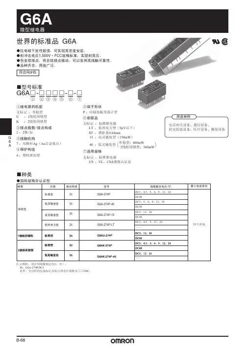
1G6RLPCB RelayLow-profile power relay with maximum switching of 10 A■Low profile: 12.3 mm in height■Max. switching capacity: 2,500 VA (NO)■Dielectric strength: 5 kV■Clearance and creepage distance: 10 mm.Applications:Boilers, PLCs, I/O ports, timers, and temperature controllersOrdering InformationNote:When ordering, add the rated coil voltage to the model number.■Model Number Legend:1.Number of Poles1:1 pole2.Contact Form/Contact ConstructionNone:SPDT A:SPST -NO3.Rated Coil Voltage3, 5, 6, 12, 24, 48 VDCSpecifications■Coil RatingsNote:1.The above items are measured at a coil temperature of 23°C.2.The tolerance of the rated current is±10%.RoHS CompliantClassificationEnclosure ratingContact formModelStandardFlux protectionSPST-NOG6RL-1ASPDTG6RL-1Rated voltage3 VDC 5 VDC 6 VDC 12 VDC 24 VDC 48 VDC Rated current 73.3 mA 44.0 mA 36.7 mA 18.3 mA 9.2 mA 5.0 mA Coil resistance 40.9Ω113.6Ω163.6Ω654.5 Ω2,618Ω9,600 ΩMust operate voltage 70% max. of rated voltage Must release voltage 10% min. of rated voltage Max. voltage 150% of rated voltage Power consumption Approx. 220 mWApprox. 240 mW2■Contact RatingsNote:P level: λ 60 = 0.1 × 10⁻⁶ / operations■Characteristics■Other dataLoad Resistive load (cos φ = 1)Rated load8 A at 250 VAC, resistive load 5A at 24VDC, resistive load Rated carry current 10 A at 250 VAC 5A at 30VDC Max. switching voltage 400VAC, 300VDC Max. switching current NO: 10 A, NC: 8 AMax. switching powerNO: 2,500 VA, NC: 2,000 VA 150 WFailure rate (reference value)10 mA at 5 VDC (P Level)Contact resistance 100 m Ω max.Operate time 10 ms max.Release time 5 ms max.Insulation resistance 1,000 M Ω min. (at 500 VDC)Dielectric strength 5,000 VAC, 50/60 Hz for 1 min between coil and contacts1,000 VAC, 50/60 Hz for 1 min between contacts of same polarity Impulse withstand voltage 10 kV between coil and contacts (1.2 × 50 µs)Vibration resistanceDestruction:10 to 55 to 10 Hz, 1.5-mm double amplitudeMalfunction:10 to 55 to 10 Hz, 0.825-mm single amplitude (1.65-mm double amplitude) when energized.10 to 55 to 10 Hz, 0.4-mm single amplitude (0.8-mm double amplitude) when not energized.Shock resistance Destruction:1,000 m/s 2Malfunction:200 m/s 2 NO, 50 m/s 2 NC when not energized Endurance (Mechanical)10,000,000 operations min. (at 18,000 operations/h)Ambient temperature Operating: −40°C to 85°C (with no icing)Ambient humidity Operating: 5% to 85%Weight Approx. 7.8 gInsulation material group IIIa Rated insulation voltage 250 V Pollution degree 32Rated voltage system 250 V 400 VOver-voltage category III Contact material AgNi Creepage distance 10 mm Clearance distance 10 mm RoHSCompliant Tracking index of relay base PTI 250Flammability class accord-ing to UL94V-0Flammability-flameGWFI (IEC 60695-2-12)GWIT (IEC 60695-2-13)850°C750°CBall pressure test (IEC 60695-10-2)170°C3■Approved StandardsUL 508 (File No. E41643)VDE (EN61810-1) (Reg. No. C266)VDE (60947-5-1) (Reg. No. C266)Electrical Endurance DataNote:The results shown reflect values measured using very severe test conditions, i.e., Duty: 3 s ON/OFF for AC loads and 1 s ON/OFF for DC loads.Electrical endurance depends on the test conditions. Consult your OMRON representative for more detailed information on the elec-trical endurance under your test conditions.ModelContact form Coil ratingContact ratingG6RL-1ASPST-NO3 to 48 VDC10 A at 250 VAC (NO)8 A at 250 VAC 5 A at 30 VDC6,000 operationsG6RL-1SPDTModelContact form Coil ratingContact ratingG6RL-1ASPST-NO3, 5, 6, 12, 24, or 48 VDC 10 A at 250 VAC (NO)10,000 operations at 85°CG6RL-1SPDT 8 A at 250 VAC 30,000 operations at 85°C 5 A at 30 VDC50,000 operations at 85°CTypeContact ratingUtilization categoryRated voltageG6RL-1(-1A)AC-15240 VAC DC-13125 VDCG6RL-1(A)8 A at 250 VAC (cos φ = 1) N.O. 50,000 operations min.8 A at 250 VAC (cos φ = 1) N.C. 50,000 operations min.5 A at 24 VDC C.O. 50,000 operations min.5 A at 24 VDC N.O.50,000 operations min.DimensionsNote:All units are in millimeters unless otherwise indicated.PrecautionsDisclaimer:All technical performance data applies to the product as such; specific conditions of individual applications are not considered. Always check the suitability of the product for your intended purpose. OMRON does not assume any responsibility or liability for noncompliance herein, and we recommend prior technical clarification for applications where requirements, loading, or ambient conditions differ from those applying to general electric applications. Any responsibility for the application of the product remains with the customer alone. THIS COMPONENT CAN NOT BE USED FOR AUTOMOTIVE APPLICATIONS.G6RL-1AG6RL-1In the interest of product improvement, specifications are subject to change without notice.ALL DIMENSIONS SHOWN ARE IN MILLIMETERS.T o convert millimeters into inches, multiply by 0.03937. T o convert grams into ounces, multiply by 0.03527.Cat. No. K133-E1-01Printed in Japan -? () (?)OMRON RELAY & DEVICES CorporationPower Relay Division Marketing Department1110, Sugi, Y amaga-city, Kumamoto-Pref., 861-0596 Japan T el: (81)968-44-4160/Fax: (81)968-44-4107。
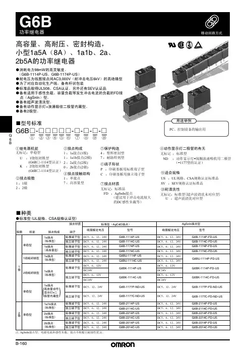
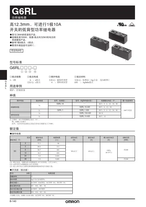
高12.3mm 、可进行1极10A开关的低背型功率继电器●高12.3mm 的低背型产品。
● 绝缘距离10mm ,线圈-接点间为5kV 耐电压的高绝缘型产品。
●备有1极a 接点、c 接点。
●最高环境温度可达85℃。
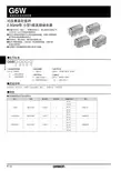
符合RoHS型号标准用途举例种类额定值G6RL ƶƶƶ-ƶüüüüķĸĹĺ①接点极数1:1极②接点构成A :a 接点无标记:c 接点③保护构造无标记:耐助焊剂型 4 :塑料密封型④接点材料无标记:标准品(Ag 合金 无Cd 材料)ASI :AgSnIn 接点锅炉、控制设备注.订购时,请注明线圈额定电压(V )。
例:G6RL-1A DC3此外,交付时的包装标记及标注的电压规格为□□VDC 。
●操作线圈注1. 额定电流、线圈电阻为线圈温度+23℃时的值,公差±10%。
注2. 动作特性为线圈温度+23℃时的值。
注3. 最大容许电压为继电器线圈能够施加的电压的最大值。
●开关部(接点部)*G6RL-1(A)、G6RL-1(A)4-ASI :AC250V 8A 、DC24V 5AB-140G 6R L性能注.左述为初始值。
*1.测量条件:根据电压下降法,在DC5V 1A的条件下。
*2.测量条件:用DC500V兆欧表测量,位置与测量耐压时相同。
*3.此值为开关频率120次/min时的值。
参考数据开关容量的最大值环境温度和动作·复位电压寿命曲线接点电流(A)动作次数(×103次)动作·复位电压(%)接点电压环境温度和最大容许电压最大容许电压(%)误动作冲击试料:G6RL-1 DC24V个数:5个测定:往3轴6个方向各加3次冲击,测出接点产生误动作的值。
规格值:200m/s2 (NO)50m/s2 (NC)ZX2注:最大容许电压为继电器线圈能够施加的电压的最大值。
B-141G6RL■外形尺寸G6RL-1A G6RL-1A-ASI G6RL-1A4-ASI端子排列/内部连接图(BOTTOM VIEW )(2.9)18.9±0.15±0.1(1.7)7.62±0.14-φ1.3±0.1孔印刷基板加工尺寸(BOTTOM VIEW )28.5 max.10.0 max.0.40.40.240.80.83.212.3 m a x.端子排列/内部连接图(BOTTOM VIEW )(1.5)18.9±0.13.2±0.13.2±0.1(1.7)7.62±0.15-φ1.3±0.1孔印刷基板加工尺寸(BOTTOM VIEW )28.5 max.10.0 max.1243512350.40.40.240.40.80.83.212.3 m a x .G6RL-1G6RL-1(-ASI)G6RL-14(-ASI)(无线圈极性)(无线圈极性)EN/IEC 规格VDE 认证型(EN61810-1)(认证No.C266)EN/IEC规格VDE 认证型(EN60947-5-1)(认证No.C266)■国际规格认证额定值UL 规格认证型(文件No.E41643)UL508B-142G 6R LEN/IEC 规格VDE 认证型(EN60947-4-1)(认证No.C266)EN/IEC 规格认证型注.不符合EMC 指令基本要求事项(EMI 标准No.·认证机构、文件No.·适合时期)。
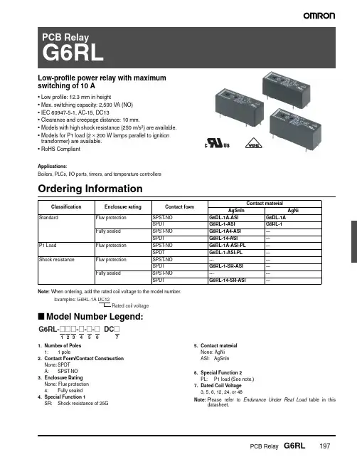
PCB Relay G6RL197Low-profile power relay with maximum switching of 10 A•Low profile: 12.3 mm in height•Max. switching capacity: 2,500 VA (NO)•IEC 60947-5-1, AC-15, DC13•Clearance and creepage distance: 10 mm.•Models with high shock resistance (250m/s 2) are available.•Models for P1 load (2 × 200W lamps parallel to ignition transformer) are available.•RoHS CompliantApplications :Boilers, PLCs, I/O ports, timers, and temperature controllersOrdering InformationNote:When ordering, add the rated coil voltage to the model number.■Model Number Legend:1.Number of Poles 1: 1 pole2.Contact Form/Contact Construction None:SPDT A:SPST -NO3.Enclosure Rating None: Flux protection 4: Fully sealed4.Special Function 1SR: Shock resistance of 25G5.Contact material None: AgNi ASI: AgSnIn6.Special Function 2PL: P1 load (See note.)7.Rated Coil Voltage 3, 5, 6, 12, 24, or 48Note:Please refer to Endurance Under Real Load table in thisdatasheet.Classification Enclosure rating Contact form Contact materialAgSnInAgNiStandardFlux protection SPST -NO G6RL-1A-ASI G6RL-1A SPDT G6RL-1-ASI G6RL-1Fully sealedSPST -NO G6RL-1A4-ASI ---SPDT G6RL-14-ASI ---P1 Load Flux protection SPST -NO G6RL-1A-ASI-PL ---SPDT G6RL-1-ASI-PL ---Shock resistanceFlux protection SPST -NO ------SPDT G6RL-1-SR-ASI ---Fully sealedSPST -NO ------SPDTG6RL-14-SR-ASI---198PCB Relay G6RLSpecifications■Coil RatingsNote:1.The above items are measured at a coil temperature of 23°C.2.The tolerance of the rated current is ±10%.■Contact RatingsNote:1.G6RL-1(A), G6RL-1(A)4-ASI: 8 A 250 VAC, resistive load; 5 A 24 VDC resistive load.2.P level: λ 60 = 0.1 × 10⁻⁶ / operations■CharacteristicsClassification Standard, P1 load Shock resistanceRated voltage 3 VDC 5 VDC 6 VDC 12 VDC 24 VDC 48 VDC 3 VDC 5 VDC 6 VDC 12 VDC 24 VDC Rated current 73.3mA 44mA 36.7mA 18.3mA 9.2mA 5mA 101mA 60.2mA 50.1mA 25.2mA 12.6mA Coil resistance40 Ω113 Ω163 Ω654 Ω2,618 Ω9,600 Ω30 Ω83 Ω120 Ω476 Ω1,912 ΩMust operate voltage 70% max. of rated voltage 80% max. of rated voltage Must release voltage 10% min. of rated voltage 10% min. of rated voltage Max. voltage 150% of rated voltage 150% of rated voltage (23°C)Power consumptionApprox. 220mWApprox. 240mWApprox. 300mWLoadResistive load (cos φ = 1)Rated load (See note 1.)10 A at 250 VAC, NO resistive load 8 A at 250 VAC, resistive load 5 A at 30 VDC, resistive load Rated carry current 10 A at 250 VAC 5 A at 30 VDC Max. switching voltage 400 VAC, 300 VDC Max. switching current NO: 10 A, NC: 8 AMax. switching powerNO: 2,500 VA, NC: 2,000 VA 150 WFailure rate (reference value)10 mA at 5 VDC (P level) (See note 2.)Contact resistance 100 m Ω max.Operate time 10 ms max. (SR Models: 15 ms max.)Release time 5 ms max.Insulation resistance 1,000 M Ω min. (at 500 VDC)Dielectric strength 5,000 VAC, 50/60 Hz for 1 min between coil and contacts1,000 VAC, 50/60 Hz for 1 min between contacts of same polarity Impulse withstand voltage 10kV between coil and contacts (1.2 × 50 μs)Vibration resistanceDestruction: 10 to 55 to 10 Hz, 1.5-mm double amplitudeMalfunction:10 to 55 to 10 Hz, 0.825-mm single amplitude (1.65-mm double amplitude) when energized.10 to 55 to 10 Hz, 0.4-mm single amplitude (0.8-mm double amplitude) when not energized.Shock resistanceDestruction: 1,000 m/s 2Malfunction: NO: 200 m/s 2, NC: 50 m/s 2 when not energized SR Models: 250 m/s 2 (NO and NC) when not energizedEnduranceMechanical: 10,000,000 operations min. (at 18,000 operations/hr)Ambient temperature Operating: −40°C to 85°C (with no icing)Ambient humidity Operating: 5% to 85%WeightApprox. 7.8 gPCB Relay G6RL199■Other Data■Approved StandardsUL Recognized (File No. E41643) - - Ambient Temp. = 85°CVDE (EN61810-1) (Certificate No.C266)Note:In progressConstruction of protection Flux protection Fully sealedInsulation material group IIIa Rated insulation voltage 250V Pollution degree 32Rated voltage system 250V 400V Overvoltage category III Creepage distance 10 mm Clearance distance 10 mm RoHSCompliant Tracking index of relay base PTI 250Flammability class according to UL94V-0Flammability-flameGWFI (IEC 60695-2-12)GWIT (IEC 60695-2-13)850°C 750°C Ball pressure test (IEC 60695-10-2)170°CModelsContact form Coil rating Contact ratingG6RL-1A SPST -NO 3 to 48 VDC10 A at 250 VAC (NO) (Resistive)8 A at 250 VAC (Resistive)5 A at 30 VDC (Resistive)6,000 operations G6RL-1SPDT G6RL-1A(4)-ASI SPST -NO G6RL-1(4)-ASI SPDT G6RL-1(4)-SR-ASISPDT3 to 24 VDC ModelsContact form Coil ratingContact rating ModelG6RL-1A-(ASI)SPST -NO 3, 5, 6, 12, 24, or 48 VDC 10 A at 250 VAC (NO)10,000 operations at 85°CG6RL-1-(ASI)SPDT 8 A at 250 VAC 30,000 operations at 85°C 5 A at 30 VDC 50,000 operations at 85°C G6RL-1A4-ASI (See note.)SPST -NO 3, 5, 6, 12, 24, or 48 VDC 10 A at 250 VAC (NO)10,000 operations at 85°CG6RL-14-ASI (See note.)SPDT 8 A at 250 VAC 10,000 operations at 85°C 5 A at 30 VDC 10,000 operations at 85°C G6RL-1(4)-SR-ASISPDT3, 5, 6, 12 or 24 VDC10 A at 250 VAC (NO)10,000 operations at 85°C8 A at 250 VAC 10,000 operations at 85°C 5 A at 30 VDC10,000 operations at 85°C200PCB Relay G6RLVDE (60947-5-1) (Certificate No. C266)Note:1.In progress2.All ratings are valid at Room TemperatureVDE (60947-4-1) (Certificate No. C266)Note:1.In progress2.All ratings are valid at Room TemperatureVDE (EN60730-1) (Certificate No. C266)Note:In progressModelsContact ratingUtilization categoryRated voltage (V)Operations G6RL-1(A)AC15 (NO)Ie: 3 A, Ithe: 10 A (A300)AC2406,000AC15 (NO)Ie: 3 A, Ithe: 5 A (B300)AC1206,000AC15 (NO)Ie: 1.5 A, Ithe: 5 A (B300)AC2406,000DC13Ie: 0.22A, Ithe: 1A (R150)DC1256,000DC13 (See note.)Ie: 0.1 A, Ithe: 1 A (R300)DC2506,000G6RL-1(A)-ASIG6RL-1(A)4-ASI (See note.)G6RL-1(4)-SR-ASIAC15Ie: 3 A, Ithe: 10 A (A300)AC2406,000AC15Ie: 3 A, Ithe: 5 A (B300)AC1206,000AC15Ie: 1.5 A, Ithe: 5 A (B300)AC2406,000DC13Ie: 0.22 A, Ithe: 1 A (R150)DC1256,000DC13 (See note.)Ie: 0.1 A, Ithe: 1 A (R300)DC2506,000ModelsContact ratingUtilization categoryRated voltage (V)Operations G6RL-1(A)G6RL-1(A)-ASI (See note.)AC18 A AC2506,000AC3 2 A AC2506,000DC1 5 A DC246,000DC32 ADC246,000ModelsContact ratingUtilization categoryRated voltage (V)Operations G6RL-1(A)2 (2) A 65°C AC250100,0008 (4) A (NO)85°CAC250100,0006 (4) A (NO)85°C (See note.)AC250100,0006 (4)A (NO)65°C AC250100,0006 (4) A (NC)65°C AC250100,000G6RL-1(A)-ASI (See note.)2 (2) A 65°C AC250100,0008 (4) A (NO)85°C AC250100,0006 (4) A (NO)85°C AC250100,0006 (4) A (NC)65°CAC250100,000PCB Relay G6RL201Electrical Endurance DataEndurance Under Real Load G6RL-1(A)-ASI-PLNote:The results shown reflect values measured using very severe test conditions, i.e., Duty: 1 s ON/OFF .Electrical endurance will vary depending on the test conditions. Contact your OMRON representative if you require more detailed information for the electrical endurance under your test conditions.G6RL-1(A)8 A at 250 VAC (cos φ = 1) NO 50,000 operations min.8 A at 250 VAC (cos φ = 1) NC 50,000 operations min.5 A at 24 VDC50,000 operations min.G6RL-1(A)-(SR)-ASI-(PL)10 A at 250 VAC (cos φ = 1) NO 100,000 operations min.8 A at 250 VAC (cos φ = 1)100,000 operations min.5 A at 30 VDC50,000 operations min.G6RL-1(A)4-ASI8 A at 250 VAC (cos φ = 1) NO 50,000 operations min.8 A at 250 VAC (cos φ = 1) NC 50,000 operations min.5 A at 24 VDC50,000 operations min.G6RL-14-SR-ASI8 A at 250 VAC (cos φ = 1) NO 50,000 operations min.3 A at 250 VAC (cos φ = 1) NC 100,000 operations min.5 A at 24 VDC NO 50,000 operations min.5 A at 24 VDC NC30,000 operations min.(Reference Only)Rated voltage ConditionFrequency Electrical life 230 VACP1 load (2 × 200 W lamps parallel to ignition transformer)1.5 s ON/4.5 s OFF250,000 operations202PCB Relay G6RLEngineering DataDimensionsNote:All units are in millimeters unless otherwise indicated.G6RL-1(A)(4)-(SR)-(ASI)-(PL)Maximum Switching CapacityG6RL-1(A)EnduranceG6RL-1(A)(4)-(SR)-(ASI)-(PL)Ambient Temperature vs.Maximum Coil VoltageG6RL-1(A)(4)-(ASI)-(PL)Ambient Temperature vs. Must Operate or Must Release VoltageNote:The “maximum coil voltage” refers to the maximum value in a varying range of operating voltage, not a continuous voltage.G6RL-1A(-ASI)G6RL-1A4(-ASI)G6RL-1(-ASI)G6RL-14(-ASI)PCB RelayG6RLMEMOPCB Relay G6RLOMRON ON-LINEGlobal - USA - Cat. No. X301-E-1bPrinted in USAOMRON ELECTRONIC COMPONENTS LLC55 E. Commerce Drive, Suite B Schaumburg, IL 60173847-882-228809/11 Specifications subject to change without noticeAll sales are subject to Omron Electronic Components LLC standard terms and conditions of sale, which can be found at /components/web/webfiles.nsf/sales_terms.html ALL DIMENSIONS SHOWN ARE IN MILLIMETERS.T o convert millimeters into inches, multiply by 0.03937. T o convert grams into ounces, multiply by 0.03527.。
公司是欧姆龙一级代理商,价格优势明显,质量有保证,有大量库存,供货期短。
欢迎新老客户来电查询联系人:1 3 5 2 0 1 1 5 8 9 1 传0 1 0- 8 0 1 1 5 5 5 5转7 5 9 7 1 13F88L-RS173G3IV-PLKEB45P53G3JV-MANUAL3G3JZ-AB0223G3MV-A4075(YES)3G3MZ-A2004-ZV23G3MZ-A2007-ZV23G3MZ-A2015-ZV23G3MZ-A2055-ZV23G3RV-B418K-ZV13G3RV-B422K-ZV13G3RV-B4900-ZV13G3RX-A4220-Z43767-0010 MC374005-3066 UM5-3066C200H-ATT01C200H-BC101-V2C200H-CP114C200H-DA001C200H-DA002C200H-ID218C200H-ID501C200H-NC111C200H-OD501C200H-TS001C200HW-COM01C200HW-COM05-EV1C200HW-DRM21-V1C200HW-NC213C500-CE405CJ1W-OD263CP1W-20EDT1(Q)CP1W-40EDT1CPM1A-20EDT1CPM1A-40CDT-A-V1 CPM2A-20CDR-DCPM2A-20CDT-DCPM2A-30CDR-DCQM1-ID211CQM1-ME04RCQM1H-PLB21CRT1-AD04CS1D-CPU44SCS1H-CPU66HCS1H-CPU67HCS1W-BAT01CS1W-BI033CS1W-CN224CS1W-OC201CS1W-PDC55CS1W-SCU31-V1D4N-212GDRT1-232C2DRT2-AD04E2E-X10D1S DC12-24 2ME3X-DAC21-S 2ME5AZ-C3E5AZ-Q3E5AZ-R3E5CN-Q2HBT AC100-240 (Q)E5CN-R2HBT AC100-240 (Q)E5CN-R2T AC100-240 (Q)E5CZ-Q2 AC100-240E5CZ-R2MT AC100-240E5EZ-C3E6C2-CWZ6C 1024P/R 2M BY OMSG3JA-C425B AC100-240 FOR CHINA G3JA-C430B AC100-240 FOR CHINA G3JA-C437B AC100-240 FOR CHINA G3JA-D420B AC100-240 FOR CHINA G3JA-D425B AC100-240 FOR CHINA G3JA-D432B AC100-240 FOR CHINA G3JA-D451B AC100-240 FOR CHINA G3PB-535B-2N-VD DC12-24H5CN-XCN AC100-240H5F-BMKS2P DC12MKS3P-5 DC48MPT-CN550NS10-TV01B-V2R7A-CNB01S-ZR7A-CNB01SB-ZR7A-CNZ01C-ZR7D-AP04HR7D-AP08HR7D-BP01H-ZR7D-BP02H-ZR7D-BP02HH-ZR7D-BP04H-ZR7D-ZP01HR7D-ZP02HR7M-A40030-S1R7M-A75030-S1R7M-Z10030-S1ZR7M-Z20030-S1ZR88A-CNG01SB-ZR88D-GN01H-ML2-ZR88D-GN02H-ML2-ZR88D-GN04H-ML2-ZR88D-GN08H-ML2-ZR88D-GN10H-ML2-ZR88D-GN15H-ML2-ZR88D-GN20H-ML2-ZR88D-GN50H-ML2-ZR88D-GN75H-ML2-ZR88D-GT50H-ZR88D-GT75H-ZR88D-WN08H-ML2R88D-WN10H-ML2R88M-G10030H-BS2-Z R88M-G10030H-ZR88M-G1K020H-S2-Z R88M-G1K020H-ZR88M-G1K020T-BS2-Z R88M-G1K020T-S2-Z R88M-G1K020T-ZR88M-G1K030H-BS2-Z R88M-G1K030H-S2-Z R88M-G1K030H-ZR88M-G1K030T-S2-Z R88M-G1K520H-BS2-Z R88M-G1K520H-S2-Z R88M-G1K520H-ZR88M-G1K520T-BS2-Z R88M-G1K520T-S2-Z R88M-G1K520T-ZR88M-G1K530H-S2-Z R88M-G1K530T-S2-Z R88M-G20030H-BS2-Z R88M-G20030T-BS2-Z R88M-G20030T-S2-Z R88M-G2K010H-S2-Z R88M-G2K010H-ZR88M-G2K010T-S2-Z R88M-G2K010T-ZR88M-G2K020H-BS2-Z R88M-G2K020H-S2-Z R88M-G2K020H-ZR88M-G2K020T-S2-ZR88M-G2K030H-S2-Z R88M-G2K030T-S2-Z R88M-G3K010H-BS2-Z R88M-G3K010H-S2-Z R88M-G3K010H-ZR88M-G3K010T-S2-Z R88M-G3K020H-BS2-Z R88M-G3K020H-S2-Z R88M-G3K020H-ZR88M-G3K020T-S2-Z R88M-G3K020T-ZR88M-G3K030H-BS2-Z R88M-G3K030H-S2-Z R88M-G3K030H-ZR88M-G40030H-B-ZR88M-G40030H-BS2-Z R88M-G40030H-ZR88M-G40030T-BS2-Z R88M-G40030T-S2-Z R88M-G4K020H-BS2-Z R88M-G4K020H-S2-Z R88M-G4K020T-S2-Z R88M-G4K030H-BS2-Z R88M-G4K030H-S2-Z R88M-G4K510H-BS2-Z R88M-G4K510H-S2-Z R88M-G4K510T-S2-Z R88M-G5K020H-BS2-ZR88M-G5K030H-BS2-ZR88M-G5K030H-S2-ZR88M-G6K010H-BS2-ZR88M-G6K010H-S2-ZR88M-G75030H-BS2-ZR88M-G75030T-BS2-ZR88M-G75030T-S2-ZR88M-G7K515H-BS2-ZR88M-G7K515H-S2-ZR88M-G7K515T-S2-ZR88M-G90010T-S2-ZR88M-GP10030H-ZR88M-GP40030H-ZR88M-W10030T-S1SH-001-01MSH-001-03MSH-001-05MSH-001-10MV400-W23 3MV400-W24 3MWLCA32-41ZR-RX20A-CHROZR-RX40A-CHROZR-XRB1ZR-XRE1我公司是欧姆龙一级代理商,价格优势明显,质量有保证,有大量库存,供货期短。
第一节继电器原理知识一、继电器的定义继电器是一种当输入量〔电、磁、声、光、热〕到达一定值时,输出量将发生跳跃式变化的自动控制器件。
继电器是具有隔离功能的自动开关元件,广泛应用于遥控、遥测、通讯、自动控制、机电一体化及电力电子设备中,是最重要的控制元件之一。
继电器一般都有能反映一定输入变量〔如电流、电压、功率、阻抗、频率、温度、压力、速度、光等〕的感应机构〔输入局部〕;有能对被控电路实现“通〞、“断〞控制的执行机构〔输出局部〕;在继电器的输入局部和输出局部之间,还有对输入量进展耦合隔离,功能处理和对输出局部进展驱动的中间机构〔驱动局部〕。
作为控制元件,概括起来,继电器有如下几种作用:1)扩大控制围。
例如,多触点继电器控制信号到达*一定值时,可以按触点组的不同形式,同时换接、开断、接通多路电路。
2)放大。
例如,灵敏型继电器、中间继电器等,用一个很微小的控制量,可以控制很大功率的电路。
3)综合信号。
例如,当多个控制信号按规定的形式输入多绕组继电器时,经过比拟综合,到达预定的控制效果。
4)自动、遥控、监测。
例如,自动装置上的继电器与其他电器一起,可以组成程序控制线路,从而实现自动化运行。
二、继电器的工作原理如下图,当控制电路中的开关K闭合时,电磁铁便具有磁性,将衔铁吸下,使继电器触点接触,与触点相连接的电源电路便接通;当控制开关K断开时,电磁铁的磁性被撤消,继电器触点弹开,电源电路亦随之断开。
三、继电器的继电特性继电器的输入信号*从零连续增加到达衔铁开场吸合时的动作值**,继电器的输出信号立刻从y=0跳跃到y=y m,即常开触点从断到通。
一旦触点闭合,输入量*继续增大,输出信号y将不再起变化。
当输入量*从*一大于**值下降到*f,继电器开场释放,常开触点断开〔如图1〕。
我们把继电器的这种特性叫做继电特性,也叫继电器的输入-输出特性。
释放值*f与动作值**的比值叫做反响系数,即K f= *f /**触点上输出的控制功率P c与线圈吸收的最小功率P0之比叫做继电器的控制系数,即Kc=P C/P0第二节.继电器的分类继电器的分类方法较多,可以按作用原理、外形尺寸、保护特征、触点负载产品用途等分类。
继电器使用说明范文
一、继电器的分类
1.常用继电器
继电器一般可分为四大类:电磁继电器、电容继电器、容性继电器及
热继电器。
(1)电磁继电器:是依靠电磁线圈构成电磁场而进行控制的,通常可
以说明电动机、变压器及直流电容器等输出电流。
(2)电容继电器:是将电容作为发射器,由电容改变电极板的电容电
压和电容容量来控制负载的其中一功能,如灯光控制、水泵控制等。
(3)容性继电器:是将容性绕组的电流变化控制负载的功能,如控制
可调谐整流开关柜、调整水泵开关等。
(4)热继电器:是依靠温度控制热继电器内元件的电阻变化而进行控
制的,常用于轻负载的开关控制,如温控控制等。
2.特殊继电器
(1)延时继电器:是将控制继电器的触点引出经过一定程序的延时而
控制负载的功能,如节电开关控制等。
(2)半桥继电器:是将继电器的主触点拆分成正极和负极,并分别引
出可控制正极和负极而控制负载的功能,如控制可变电容器等。
(3)调速器继电器:是将继电器作为调速器的发射器,将电流送入调
速器的调节腔以改变电路中的电容容量而控制负载的功能,如控制变速箱、风机功率调节等。
欧姆龙OMRON缺相电机保护器相序继电器说明书OMRON缺相电机保护器主要由继电器、电动空载电流互感器、电气控制单元组成。
如果缺相的电机过流,就会出现电机过热现象。
如果缺相时间太长,可能会使电机损坏。
因此当缺相情况发生时,要及时对缺相电机进行保护,装置的作用就是保证电机不继续工作了。
OMRON自动控制单元可以在整个电流系统中自动实现多个动作及状态的切换(断开开路方式)。
当缺相时间较长时,要及时处理故障(关闭断路);当缺相时间较短时,如能对缺相系统进行及时控制(断开),使系统在短时间内恢复正常运行即可;当缺相时间过长时,如能对相关动作及状态进行及时控制,则可以避免影响整个电源线路系统(整个电路板)的运行。
•一、主要参数1、使用方法:在有条件下将电源接入控制单元,如在没有条件下将电源接入控制单元,应先开启电源开关,再关闭。
2、结构:根据保护原理图,该结构类似于电动机保护功能。
其中:1.电动机动作时间:以电动机停转的时间为准,启动时间过大则不动作;2.启动电流:以电动机停止转电流为准.3.负载转矩:以电动机的转矩为准.4.保护功能:对缺相电机进行保护性隔离处理.5.运行方式:在需要时手动操作。
6.特殊说明:对于缺相电机保护而言,本设计提供两种不同的保护方式;一种是自动型动作方式(手动型)、一种是自动型切换方式(手动型)。
7.结构形式:固定安装于电路板上,由面板(4个按键)、电气控制单元和继电器组成。
•二、性能特点●无需人工干预,自动完成各种动作;●自动操作多个动作及状态;●保护、跳闸、自动关机;●适用于缺相、断相等各种情况下;●当无相电压电流变化或缺相产生时;●当缺相电流超过额定电流。
•三、操作要点当缺相电机出现故障时,要将保护动作并断开相序继电器,在其断开时保护继电器应闭合,以防由于电机的机械冲击造成相序继电器损坏。
如果故障消失后需要继续运行,可重新断开相序继电器,直到找到故障原因。
如果不能及时得到诊断并修复,可以继续运行保护电机接线的一部分;在工作中经常遇到这样的问题:由于缺乏对设备本身和运行环境的了解,为了便于检测电动机及其接线是否有故障而进行判断和调节;当检查电动机时发现有异常情况发生就应立即对其断开开关;保护在运行中必须注意控制措施。
天龙继电器说明书
故障码:
发动机启动马达继电器电路电压高于正常值或对高压电源短路,历史故障。
查看电路图发现整车的启动原理为:
1. 打开钥匙门,ECU上电;
2. ECU给启动保护继电器控制线供电,继电器吸合;
3. 拧到启动档T50信号经过空挡开关,经过启动保护继电器负载端导通,到达启动继电器的控制端线圈搭铁;
4. 启动继电器负载端吸合,启动机开始运转。
排查步骤:直接短接启动继电器负载端,启动机运转,说明启动机及线束正常,故障点在控制线路。
根据电路原理图可知,根据电路图测量启动继电器的控制端须有24V电,由启动保护继电器的负载端过来的,实际测量没有电。
检查启动保护继电器,测量负载端无24V,继续检查空档开关测量发现仍然无24V。
顺着线继续检查在空档开关线束转换接头,断开接头能够测量到24V但接头连接上无24V输出。
观察发现针脚腐蚀退针。
直接将线束跨接相连处理,故障排除。
故障总结:
处理东风天龙、天锦系列车型,配康明斯CM2150电脑板,要详细了解启动电路控制逻辑,按串联顺序逐一排查故障。
另外东风配博世EDC17电脑板如下图,控制方式发生改变。
启动机继电器直接连接到ECU,但T50信号需要经过空档继电器,而空档继电器的吸合需要,钥匙门在ON档位经过空档开关到达空档继电器的1及2控制回路搭铁才闭合。
欧姆龙继电器参数一、继电器的概述继电器是一种电气控制装置,可以通过小电流控制大电流的开关。
它由电磁线圈和一对可触碰或不可触碰的触点组成。
继电器广泛应用于工业自动化、家庭电器等领域。
二、欧姆龙继电器的特点欧姆龙是世界知名的电子元器件制造商,其继电器产品以质量可靠、性能稳定著称。
以下是欧姆龙继电器的一些主要特点:1. 高可靠性欧姆龙继电器采用优质材料和制造工艺,具有较高的抗震、抗振和抗干扰能力,能够在恶劣环境下稳定工作。
2. 多种类型选择欧姆龙提供多种类型的继电器,包括电压型继电器、电流型继电器、温度型继电器等,可以满足不同应用场景的需求。
3. 合理的尺寸和安装方式欧姆龙继电器采用标准化设计,方便安装和维护。
尺寸小巧,适用于空间有限的场合。
4. 丰富的额定参数欧姆龙继电器的额定参数包括额定电压、额定电流、额定功率等,用户可以根据具体需求选择合适的参数。
三、欧姆龙继电器参数表参数描述额定电压继电器正常工作的电压额定电流继电器正常工作时的电流额定功率继电器正常工作时的功率工作温度范围继电器可靠工作的温度范围联结类型继电器触点的联结方式绝缘电阻继电器触点间与继电器外壳之间的绝缘电阻寿命继电器的使用寿命四、欧姆龙继电器的应用领域1. 工业自动化欧姆龙继电器广泛应用于工业自动化控制系统中,如机床控制、自动化生产线控制等。
其稳定的性能和可靠的质量保证了工业生产的正常运行。
2. 家庭电器欧姆龙继电器也被广泛应用于家庭电器中,如空调、洗衣机、电饭煲等。
它可以实现家电设备的控制和保护,确保用户的使用安全。
3. 智能建筑在智能建筑领域,欧姆龙继电器可以用于灯光控制、空调控制、门窗控制等,实现对建筑设备的智能化管理和节能控制。
4. 能源管理欧姆龙继电器还可以应用于能源管理系统中,如电力监控、电能计量等。
它能够提供精确可靠的数据支持,帮助用户进行科学管理和节能减排。
五、继电器的选型和安装注意事项1. 根据实际需求选择合适的继电器型号和参数在选择继电器时,需要根据实际的工作电压、电流和功率等需求来确定。
欧姆龙继电器参数1. 欧姆龙继电器概述欧姆龙继电器是一种能够在电路中起到控制和保护作用的电器元件。
其主要功能是在电路中实现开关、延时、保护等功能。
欧姆龙继电器具有结构简单、易于制造、操作可靠等特点,广泛应用于机械、自动化、电力、通讯等领域。
2. 欧姆龙继电器的使用条件欧姆龙继电器的使用条件包括电压、电流、温度等参数。
其中,电压是指继电器的工作电压,通常为DC或AC电压;电流是指继电器的最大负载电流,通常为几十A或几百A;温度是指继电器的工作环境温度,通常为-40℃~85℃之间。
3. 欧姆龙继电器的参数分类欧姆龙继电器的参数可分为额定参数和动作参数两类。
额定参数包括额定电压、额定电流、额定功率等,表示继电器正常工作时最大的电压、电流和功率。
动作参数包括吸合电压、吸合电流、释放电压、释放电流、动作时间等,表示继电器开始动作时所需的电压、电流以及动作时间。
4. 欧姆龙继电器的型号解析欧姆龙继电器的型号通常由多位字母和数字组成,其中字母代表产品系列,数字代表特定模型。
以G2R系列继电器为例,其中G代表该系列,2R代表双触点继电器。
另外,该系列继电器还包括玻璃板和塑料板两种材质选择,可以通过在型号中加入G、N和L来区分。
5. 欧姆龙继电器的优点欧姆龙继电器的主要优点包括反应速度较快、可靠性高、结构简单、易于组装和更换、价格相对较低等。
此外,欧姆龙继电器还具有一定的抗干扰能力,能够有效地防止电路中干扰信号的影响。
6. 欧姆龙继电器的应用领域欧姆龙继电器广泛应用于自动化控制系统、电力系统、汽车电子、电器设备、医疗器械等领域。
在自动化控制系统中,欧姆龙继电器主要用于控制启动、停止、保护等,是自动化控制领域中不可缺少的关键元素。
在电力系统中,欧姆龙继电器主要用于保护电路、隔离故障等。
7. 欧姆龙继电器的未来发展方向随着科技的不断发展,欧姆龙继电器也在不断升级和改进。
未来,欧姆龙继电器的发展方向主要包括以下几个方面:(1)集成化:欧姆龙继电器不仅要实现单一功能,还要实现多功能集成化。