扭矩功率测试仪使用说明书
- 格式:pdf
- 大小:224.33 KB
- 文档页数:4

User ManualTable of ContentsService and Warranty (3)Overload Capacity Caution (3)System Overview (3)Battery Chargers (5)Standard Equipment (5)Instructions for Using the Driver Adapter (6)Usage (7)Procedure for Manual Torque Screwdrivers (7)Procedure for Power Screwdrivers (7)Battery Indicator (8)Basic Function (8)Display of Clockwise/Counter-Clockwise (8)Zeroing the Tester (9)Changing the Unit of Measure (9)Changing the Mode of Measure (9)Backlit Display (10)Saved Reading to Memory (10)Main Menu (10)Setting (10)Auto-Shutdown (11)Auto-Reset (11)Pass-Fail (12)Load Default (13)Memory (13)View (13)Delete Last (14)Delete All (14)Calibration (14)Transducer State (15)About (15)Service and WarrantyOverload Capacity CautionASG, Division of Jergens, Inc., warrants to the original purchaser buying the ASG DTT-L meter with the intention of use rather than resale, for a period of 1 year. ASG will replace those items found to be defective or otherwise fail to conform, or at ASG’s option repay the price paid for the item. The buyer’s remedies with respect to any item found to be defective or otherwise not conforming shall be limited exclusively to the right of replacement or repayment. In no event shall ASG be liable for any incidental, special or consequential damages or for damages in the nature of penalties.DISCLAIMER: Seller makes no other warranty what-so-ever, expressed or implied, and all implied warranties of merchantability and fitness for a particular purpose are disclaimed and excluded from this transaction and shall not apply to the goods sold hereunder. The ASG DTT-L meter is an electronic instrument and should be treated with the same care given any sensitive electronic instrument. Avoid dropping the unit or dropping items on the unit. Avoid high shock loads to the transducer. Use the proper driver adapter when using clutch type power tools.Do not exceed the capacity of the unit. The overload capacity of a DTT-L meter is 200% of its maximum load capacity. If the meter is taken over capacity, a warning tone will sound, the word “OVERLOAD ” will flash on the LCD, and the unit will LOCK until the RESET button is pressed. Immediately stop applying torque when the overload warnings are observed. A unit subjected to overload or subjected to harsh conditions, such as use with an impact tool, will not be covered under warranty.System OverviewSystem Overview (Continued)* DTT-200 and DTT-500 come with mounting plateStandard EquipmentAll DTT-L meters are supplied with the following standard items: • DTT-L torque meter• Battery charger/Power adapter• NOTE: Rundown adapters sold separately; International charger also sold separatelyBattery Chargers9 Volt, 500 mA, 90-264 VDC US Power Adapter (Supplied)9 Volt, 670 mA, 90-264 VDC International Power Adapter (Optional, Must Order Separately)ASG #66603ASG #66619Instructions for Using the Rundown AdaptersBelow is a list of all rundown adapters ASG offers for the DTT and DTT-L Series• Rundown adapters are included with the DTT torque testers. See charts in DTT manual on page 6 for more information. • Rundown adapters are not included with the DTT-L torque tester, choose the needed rundown adapters from the chart belowwhen ordering the tester.* ASG Adapter #66612 comes with two springs covering torque range from 1.3-5.0 lbf.in (0.15-0.56) and 4.5-26.0 lbf.in (0.51-2.94 N.m)ASG #66620ASG #66631ASG #66612ASG #66633ASG #66635ASG #66618ASG #66639ASG #66634ASG #66617ASG #66642UsageProcedure for Manual Torque Drivers• Attach a proper adapter to connect the driver to the 3/8” female square.• NOTE: It is NOT recommended to use the power tool adapters to calibrate hand torque tools.• Select FIRST PEAK mode using the MODE button. Press the RESET button if the display is not at 0.• Turn the driver or wrench clockwise or counterclockwise until the “break” point is reached.• In FIRST PEAK no other reading can then be displayed until the reset button is pressed.• The LCD display will show the torque that the driver or wrench is set at. Note the reading or write it down. To enter it into the DTT-L memory press the ENTER/MEM button. If you are testing several tools, note the memory numbers of the readings for the various tools. This number is in the upper right hand corner of the LCD. The unit can save up to 200 readings. After that, no further readings can be entered until the memory is cleared.• If the torque is not correct, adjust the tool. Repeat the test. When the reading is proper, perform the test several times to be sure the readings are consistent. The proper reading may be an average of several readings.Procedure for Power Screwdrivers• Put the appropriate rundown adapter into the unit’s female 3/8” square socket. It allows the power tool to reach its working speed before tightening up and causing the clutch to operate.• Run the tool in reverse to make sure the adapter is unwound. Do not disassemble the driver adapter.• Make sure the unit is in PEAK mode. If it is not, use the MODE button to select PEAK mode.• Press the ZERO button to be sure the display is at 0.• Run the tool forward until it shuts off. The reading on the display will be the torque setting of the tool’s clutch. Note the reading or write it down.• To enter it into the units memory, press the ENTER/MEM button. If you are testing several tools, note the memory numbers of the readings for the various tools. This number is in the upper right hand corner of the LCD. The unit can save up to 200 readings. After that no further readings can be entered until the memory is cleared.• If the torque is not correct, adjust the clutch. Repeat the test. When the reading is proper, perform the test several times to be sure the readings are consistent. The proper reading may be an average of several readings.• Always unwind the rundown adapter after each test. Do NOT leave the spring under tension while not in use.Battery IndicatorBasic FunctionDisplay of Clockwise/Counter-ClockwiseBatteryBattery Level > 5.00V 4.99V > Battery Level > 4.8V 4.79V > Battery Level > 4.7V 4.69V > Battery Level > 4.65V Battery Level < 4.65Vrecognized by the symbol “CCW.”Clockwise symbolLoad indicator bar for clockwiseLoad indicator clockwiseCounter-clockwise symbolA load indicator bar alerts the operator as to how much torque load is being applied to the transducer as related to its full scale rating.Before using the unit, make sure the battery has been charged. If the battery is low, the LCD may not function. If the battery dies during use, the on/off switch will need to be cycled to use the unit after the charger is connected. Allow the battery to fully charge then detach the charger. CAUTION: If the battery overheats during charging a thermal fuse will open. The unit will not operate until the fuse resets. Allow the DTT meter to sit for up to 30 minutes with the charger disconnected then turn the unit back on.If the battery level is less than 4.6 V , the “Battery Empty ” message will be displayed and the tester will power down automatically. When battery charger is connected and battery is charging, the plug icon will blink. NOTE: Only use the 9V adapter/charger supplied. The supplied charger is a battery charger only. It is not to be used as an AC adapter to power the DTT meter in place of using the batteries in normal operation.While operating the tester, it may be necessary to zero the display so that residual torque does not become part of the measured reading. Press and release the ZERO key.You can choose from the following modes of measure: Track, First Peak, and Peak . To change the display mode, press the MODE key. Each time the MODE key is pressed, it will select the next available mode until the tester returns to its original setting.You can choose from the following units of measure depending on the capacity of your tester: N.mm (not available on the DTT-L 500), N.cm, N.m, kgf.cm, kgf.m, lbf.in, and lbf.ft. To change the display units, press the UNIT key. Each time the UNIT key is pressed, it will select the next available unit until the tester returns to its original setting. The DTT-L automatically converts readings as new units of measure are selected.NOTE: All units may not be displayed depending on tester capacity.Basic Function (Continued)Zeroing the TesterChanging the Mode of MeasureChanging the Unit of MeasurePress the MODE key until “Track” appears on the display. The display will now indicate the torque applied in either direction as it is applied to the transducer.Press the MODE key until “Peak” appears on the display. The display will show the maximum torque applied to the transducer during a cycle.Press the MODE key until “FPeak” appears on the display. The display will show the torque level applied to the transducer.Track ModePeak ModeFirst Peak ModeAny reading can be saved anytime by pressing the MEM key. A total of 200 readings can be stored in the database including the reading unit.Basic Function (Continued)Saved Reading to MemoryWhen you press any key or apply torque to the transducer greater than 0.5% of full scale, the backlight will go on for 60 seconds.Backlit Display• To access the SETTING menu, press the MENU/ESC key. Use the UP or DOWNARROW keys to move the cursor to SETTING . Press ENTER.• To move between the submenus listed in the SETTING menu, press the UP orDOWN ARROW keys to move the cursor. The sub-menus in the setting menu are auto-shutdown, auto-reset, pass-fail, and load default.• Press ENTER to select the sub-menus, activate feature and enter values. Withinsub-menus the UP , DOWN , LEFT and RIGHT ARROW keys will also change numerical values.• Press ESC to return to the setting menu pageSettingMain Menu• Press the MENU/ESC key to access the main menu• To move between the sub-menus listed on the main menu page, press the UP orDOWN ARROW keys to move the cursor • Press ENTER to select the sub-menus, activate features and enter values.Within sub-menus, UP , DOWN , LEFT and RIGHT ARROW keys will also change numerical values.• Press ESCto return to the main menu pageThe Auto-Reset feature is used to automatically reset the reading value in peak mode. This mode works when the reading value is higher than the setting value, causing the peak value to change to a new held value. The user does not need to press the RESET key, since the peak value will automatically reset. This feature works in peak mode only. If this feature is activated, the icon “AR” will display on main display.• To set Auto-Reset, press the MENU/ESC key, the display will show the main menu page. Use the UP and DOWN ARROW keys to move the cursor point to SETTING . Press the ENTER key and use the UP and DOWN ARROW keys to move the cursor point to A UTO-RESET . Press the ENTER key. The display will show the Auto-Reset menu page.• Press the ESC key to return the main menu page• Use the UP and DOWN ARROW keys to change the value. Use the RIGHT ARROW key to change the unit. Press ZERO key to reset value to zero. Press ENTER key to set new value and return to setting menu. Press ESC to return to setting menu.• Auto-Reset feature will automatically be disabled if you set AUTO-RESET = 0• To set Auto-Shutdown, press the MENU/ESC key, the display will show the main menu page. Use the UP and DOWN ARROW keys to move the cursor point to SETTING . Press the ENTER key and use the UP and DOWN ARROW keys to move the cursor point to AUTO-SHUTDOWN . Press the ENTER key. The display will show the Auto-Shutdown menu page.• The Auto-Shutdown feature can be enabled to conserve battery power where the meter powers down after 5, 10, and 15 minutes (depending on auto-shutdown time) since the last key press. Use the UP and DOWN ARROW keys to move the cursor to the auto-shutdown time preferred and press ENTER.• Press ESC key to return to the main menu page. If you activate this feature, the OFF symbol will be displayed on the main display.Auto-ResetAuto-ShutdownMain Menu (Continued)Main Menu (Continued)The pass-fail feature is used to set a defined acceptable maximum and minimum torque range for measuring. It is activated by setting the lower level and upper level torque limit. As long as the torque value is within this range, the green LED display button will light up OK. Any reading values outside this range (higher or lower), the orange LED display buttons will light up. The orange up arrow will light up if the torque range is higher than the set range and the orange down arrow will light up if the torque range is lower than the set range. If this feature is activated, the PF symbol will display on the main display.• To access the Pass-Fail menu, press the MENU/ESC key, the display will show the main menu page. Use the UP and DOWN ARROW keys to move the cursor point to SETTING . Press the ENTER key and use the UP and DOWN ARROW keys to move the cursor point to PASS-FAIL . Press ENTER . The display will show the Pass-Fail menu page.• Press the ESC key to return the main menu page• Use the UP and DOWN ARROW keys to change the value. Use the RIGHT ARROW key to change the unit. Use the LEFT ARROW key to toggle between the upper and lower limits. Press the ZERO key to reset value to zero. Press the ENTER key to set new value and return to setting menu. Press ESC to return to setting menu.NOTE: Lower level must be less than the upper levelPass-FailMain Menu (Continued)MemoryThis is used to view the saved record, delete the last record, or delete all records.• To access the Memory menu, press the MENU/ESC key, the display will show the main menu page. Use the UP and DOWN ARROW keys to move the cursor point to MEMORY . Press the ENTER key. The display will show the Memory menu page.• In this sub-menu, memory is able to be viewed, delete last, or delete all • Press the ESC key to return to the main menu pageViewLoad DefaultThis is used to view all saved records in memory. The detail of each saved record consists of mode, reading value with unit, and direction.• To access the View menu, press the MENU/ESC key, the display will show the main menu page. Use the UP and DOWN ARROW keys to move the cursor point to MEMORY . Press the ENTER key. Press the UP and DOWN ARROW keys to move the cursor point to VIEW and press the ENTER key.• Use the UP and DOWN ARROW keys to scroll through the readings • Press the ESC key to return to the memory menu pageThe Load Default setting is used to restore the auto-shutdown, auto-reset, and pass-fail to its original setting. These features will all be turned off.• To access the Load Default menu, press the MENU/ESC key, the display will show the main menu page. Use the UP and DOWN ARROW keys to move the cursor point to SETTING . Press the ENTER key. Press the UP and DOWN ARROW keys to move the cursor point to LOAD DEFAULT and press the ENTER key.• Press the ENTER key to reset to default settings• Press the ESCkey to return the main menu pageMain Menu (Continued)Delete AllCalibrationThis is used to delete all saved records.• To access the Delete All menu, press the MENU/ESC key, the display will show the main menu page. Use the UP and DOWN ARROW keys to move the cursor point to MEMORY . Press the ENTER key. Press the UP and DOWN ARROW keys to move the cursor point to DELETE ALL and press the ENTER key. Press the UP or DOWN ARROW keys to move the cursor point to DELETE ALL and press the ENTER key. The display will show the Delete All menu page.• Press the ESC key to return to the memory menu page• Press the UP or DOWN arrow keys to select NO or YES . If you select NO and press the ENTER key, the meter will return to the memory menu page. If you select YES and press the ENTER key, the meter will delete all saved records andreturn to the memory menu page.Delete LastThis is used to delete the last saved record.• To access the Delete Last menu, press the MENU/ESC key, the display will show the main menu page. Use the UP and DOWN ARROW keys to move the cursor point to MEMORY . Press the ENTER key. Press the UP and DOWN ARROW keys to move the cursor point to DELETE LAST and press the ENTER key. The display will show the Delete Last menu page.• Press the ESC key to return to the memory menu page• Press the UP and DOWN ARROW keys to select NO or YES . If you select NO and press the ENTER key, the monitor will return to the memory menu page. If you select YES and press the ENTER key, the meter will delete the last saved recordand return to the memory menu page.ASG service technicians to calibrate the meter; please contact ASG for additional calibration information.Main Menu (Continued)AboutThis shows the information regarding your tester (model, capacity, firmware revision, serial number).• To access the About menu, press the MENU/ESC key, the display will show main menu page. Use the UP and DOWN ARROW keys to move the cursor point to ABOUT . Press the ENTER key. The display will show the ABOUT menu page.• Press the ESC key to return to the main menu pageTransducer StateThis is used to check the status of the transducer. If you suspect that your transducer has sustained an overload, check the status of the transducer immediately. To access the Transducer State menu, press the MENU/ESC key, the display will show main menu page. Use the UP and DOWN ARROW keys to move the cursor point to TRANSDUCER STATE . Press the ENTER key. Press the UP and DOWN ARROW keys to move the cursor point to VIEW and press the ENTER key.• Place the meter horizontally on a flat level surface and go to the main menu page • Use the UP and DOWN ARROW keys to move the cursor point to TRANSDUCER STATE and press the ENTER key• The display will show the TRANSDUCER STATE menu page. Press the ESC key to return to the main menu page• If the % offset is greater than 10%, please contact ASG to arrange for evaluation • Transducer state offset number is for reference only and does not determine whether the transducer is yielded• These values are given only as an indicator – the need for repair may varyaccording to the individual characteristics of the transducer。
扭矩测试操作手册
目的
本操作手册旨在指导使用者正确使用扭矩测试仪进行测试,确保测试的准确性和一致性。
扭矩测试仪简介
扭矩测试仪是一种用于测量物体扭转力的仪器。
它通常由一个转动的扭矩传感器和一个数据记录设备组成。
操作步骤
1. 将被测试物体放置在水平表面上,并确保其固定不动。
2. 将扭矩测试仪的扭矩传感器连接到测试物体上。
3. 打开数据记录设备,并确保其与扭矩传感器正确连接。
4. 调整数据记录设备的设置,包括采样率和单位。
5. 开始测试前,将扭矩测试仪的初始值设置为零。
6. 按照实验要求,以适当的速度施加扭矩力到被测试物体上。
7. 当测试物体达到目标扭转角度或其他指标时,记录扭矩传感器显示的数值。
8. 停止测试,并将测试结果保存至数据记录设备中。
9. 断开扭矩传感器与测试物体的连接。
注意事项
- 在使用扭矩测试仪之前,确保该仪器已经经过校准并处于良
好工作状态。
- 在进行测试之前,检查测试物体是否安全固定,以防止意外
损伤或伤害。
- 在进行测试时,遵循实验要求,并按照正确的步骤进行操作。
- 在记录测试结果时,确保准确记录扭矩传感器显示的数值,
并根据需要进行单位转换。
- 如果发现任何异常情况,如扭矩传感器异常或测试物体不稳
定等,请立即停止测试,并及时排除故障。
总结
扭矩测试操作手册提供了使用扭矩测试仪进行测试的详细步骤
和注意事项。
正确使用扭矩测试仪可以确保测试结果的准确性和一
致性。
在进行测试前,请仔细阅读本操作手册并遵循相应的操作步骤。
数字扭矩仪使用说明书Ver 0.01SHIMPO1.本产品的特点z可以测得开栓方向或闭栓方向的扭距z可以用USB向电脑传输数据z可以测得峰值(峰值保持)z存储功能可以最多存储1000个计测时的峰值。
z比对功能可以判断产品的合格与否(判定结果通过LED显示)z由于采用了镍氢电池,没有AC适配器也可以方便地使用。
z额定扭距为2N、5N、10N的机种。
z可以切换为各种单位(国内只可以转换)z计测周期(显示周期)最大可从8次/秒中选择。
2.各部分名称及工作2.1主机部分■ (前面)①Power键键键键键⑥液晶显示部分①Power キー用于电源的开/关②Recall キー开栓计测或闭栓计测模式时读取已存储的数据※平均计测模式时不能读取存储数据。
用于功能模式时③Mem キー在开栓计测或闭栓计测模式下将保持峰值输入、存储。
※平均计测模式下不能存储输入。
用于存储数据完全清除时用于功能模式时。
④Mode キー切换计测模式。
读取存储数据时按本按钮会返回计测模式。
在功能模式时使用。
⑤Zero/RST キー平均计测模式时:进行归零开栓、闭栓计测模式时:进行峰值归位用于功能模式启动时用于功能模式时⑥液晶显示部分显示计测数据、计测单位⑦计测模式显示灯中有一个灯亮,表示计测模式。
⑧对比判定显示灯对比判定有效的情况下,中一个灯亮,表示对比判定结果。
平均模式:对计测数据进行比较、判断后显示其结果。
开栓计测、闭栓计测模式:用比对器对保持了的峰值进行判定,显示结果。
用比对器进行判定无效时,灯不亮。
4/153. 显示部分3.1 各部分名称3.2 数值显示部分用符号和4位数值显示测定值。
开栓方向扭距用正数、闭栓方向的扭距用负数来显示。
3.3 单位显示部分显示单位。
过载的时候显示“OVR ”。
在自动关机前1分钟内显示“PWR ”。
5/15充电显示部分 单位显示部分数值显示部分(测量值显示)自动关机前1分钟内 过载3.4充电显示部分根据充电状态会显示如下数据:内置镍氢电池的电压降低时“LO BAT”闪烁。
标准扭矩测试仪使用方法一、前期准备1.确保标准扭矩测试仪处于正常工作状态,并检查仪器是否完好无损。
2.准备被测物体,并确保其表面光滑、无明显损伤。
3.确定测试的目的和要求,例如测量精度、测试范围等。
二、仪器设置1.将标准扭矩测试仪放置在平稳的水平台上,并确保仪器底部与平台充分接触。
2.按照仪器说明书的要求,连接电源线,并确保电源正常供应。
3.根据被测物体的大小和形状,选择合适的夹具或夹具配件,并将其安装到测试仪上。
4.打开仪器电源,并根据需要设置测试模式、单位和显示方式等。
三、测试步骤1.将被测物体固定在测试夹具上,并确保夹具牢固可靠。
2.根据被测物体的旋转方向,调整测试仪的测量方向和测量头。
3.启动测试仪,并根据需要进行预热或校准等操作。
4.将测试仪的测量头放置在被测物体的扭矩传递位置,确保测量头与物体充分接触。
5.对被测物体施加扭矩,直到达到预定的测试数值或测试结束标准。
6.读取测试仪的显示结果,并记录测试数值和时间等相关信息。
7.根据需要,重复测试步骤2-6,以获得准确可靠的测试数据。
四、测试结果分析1.将测试仪的显示数值与预期数值进行比较,判断测试结果的准确性。
2.根据测试结果进行数据处理和分析,如计算平均值、最大/最小值、标准差等统计指标。
3.将测试结果与标准要求进行比较,判断被测物体的扭矩性能是否符合规定标准。
4.如有必要,进行相关的校正或调整,以提高测试仪的准确性和可靠性。
总结:标准扭矩测试仪使用方法包括前期准备、仪器设置、测试步骤和测试结果分析等。
正确使用标准扭矩测试仪将帮助我们准确测量和校准扭矩,确保产品的质量和性能。
在实际应用中,应根据具体需求和仪器的要求进行操作,并定期进行维护和保养,以确保仪器的正常使用和长期稳定性能。
扭矩仪作业指导书一、引言扭矩仪是一种用于测量和控制旋转装置扭矩的仪器。
本作业指导书旨在提供详细的操作步骤和注意事项,以确保扭矩仪的正确使用和安全操作。
二、设备准备1. 确保扭矩仪处于正常工作状态,检查仪器的电源和连接线是否正常。
2. 准备所需的测试样品和附件,如螺栓、螺母等。
3. 检查扭矩仪的测量范围是否适合于所需测试。
三、操作步骤1. 将扭矩仪放置在平稳的工作台上,并连接电源线。
2. 打开扭矩仪电源开关,等待仪器启动并进入工作状态。
3. 根据需要选择合适的测量单位和显示模式。
4. 将待测样品装入扭矩仪夹持装置中,并确保样品与仪器的接触良好。
5. 调整扭矩仪的初始零位,确保仪器的测量准确性。
6. 开始测试前,确保测试环境的温度和湿度符合仪器的要求。
7. 选择合适的测试模式,如静态测试或者动态测试。
8. 根据测试要求设置合适的测试参数,如测试时间、测试角度等。
9. 启动测试程序,观察扭矩仪的测量结果并记录数据。
10. 根据需要进行多次测试,以确保结果的稳定性和可靠性。
11. 完成测试后,关闭扭矩仪电源开关并断开电源线。
四、注意事项1. 在操作过程中,严禁将手指或者其他物体放入扭矩仪的夹持装置中。
2. 避免将扭矩仪暴露在高温、潮湿或者腐蚀性环境中,以免损坏仪器。
3. 在使用扭矩仪进行测试前,应先进行仪器的校准和检查,确保其准确性和可靠性。
4. 在进行动态测试时,要确保测试样品的旋转速度和角度范围符合仪器的要求。
5. 定期清洁扭矩仪的表面和夹持装置,以保持仪器的正常工作状态。
6. 在使用扭矩仪时,应遵守相关的安全操作规程,如穿戴适当的防护设备。
五、维护与保养1. 定期对扭矩仪进行维护和保养,包括清洁仪器表面、检查电源线和连接线是否正常等。
2. 如发现仪器存在故障或者异常情况,应即将住手使用并联系专业人员进行修理。
3. 在长期不使用扭矩仪时,应将其存放在干燥、通风的地方,并拔掉电源线。
六、故障排除1. 如扭矩仪无法启动或者显示异常,首先检查电源线和连接线是否正常连接。
电气操作说明书本手册提供扭矩检测机的操作指导。
操作员须依照本手册的指导,正确地操作扭矩检测机。
对于本手册未描述的操作细节,请按天源厂工程师的指导。
1.系统组成:1.1 车床数控系统 GREAT-150iT-Ⅱ1.2 伺服驱动器伺服电机1.3 扭矩测量仪 JN338M-F2. 操作程序2.1 操作前检查2.1.1 检查电源是否准备好。
2.1.2 检查高压空气是否准备好。
▲警告·操作前检查必须在机器停止的时候进行。
否则将会发生意外伤害和机器破坏等事故。
2.2 运转操作2.2.1 打开气源阀门。
2.2.2 将控制柜右侧的“总电源”断路器置ON。
第一次开机须将柜内的各分断路器合上。
2.2.3 确认控制柜面板上的灯“电源”点亮。
2.2.4 在确定机器的周围安全后,压下操作主面板上的“ESC”按键开设备进入准备状态。
2.2.5 手动是指手动操作运行。
在面板下,按“手动”软键后,即可进入手动界面,在手动状态下可以进行各部分的单独运行:a) X轴(卡盘旋转)操作:按下副面板上的“”“”按键,卡盘将正转或反转,松开按键即停止。
b) Z轴(压头轴向移动)操作:按下副面板上的“”“”按键,压头拖板将向左或向右移动,松开按键即停止。
注意:Z轴移动必须在压头打开状态下进行。
c) 顶尖操作:交替按下副面板上的顶尖(图标)按键,顶尖将前进或后退。
d) 卡盘操作:交替按下副面板上的卡盘(图标)按键,卡盘将夹紧或打开。
e) 压头操作:交替按下副面板上的压头(K5)按键,压头将夹紧或打开。
2.2.6 回参考点:每次开机后,机器需要回参考点;首先在手动状态下将压头拖板移动到中间位置,使它脱离原点位接近开关,然后按下副面板上的回参考点(图标)按键,在弹出的对话框中输入A 后,按Enter 键则按X→Z 轴的顺序依次返回参考点,当对应的轴回参考点完成后,轴坐标前的圆圈应为绿色,否则回参考点失败。
2.2.7 工件装夹:a)在手动状态下使顶尖退回,压头打开,卡盘打开,然后把工件装入卡盘及顶尖工件托中;b)按下副面板上的顶尖(图标)按键,或踩脚踏开关,顶尖前进顶住工件;c)按下副面板上的“”“”按键,移动压头拖板,使压头对准第一只凸轮片;d)按下副面板上的压头(K5)按键,压头将工件压住;e)用手转动凸轮轴,使第一片凸轮直边紧紧压住内侧压头(操作位侧);f)盖上护罩2.2.8 在自动加工前,首先要在“程序”界面下选择加工程序。
扭矩仪作业指导书1. 引言本文档旨在为操作人员提供扭矩仪的操作指导,以确保正确、安全地使用扭矩仪进行工作。
请在使用扭矩仪之前仔细阅读本指导书,并按照其中的步骤进行操作。
2. 扭矩仪的概述扭矩仪是一种用于测量和控制旋转装置扭矩的工具。
它通常由一个测力传感器、一个转动装置和一个显示器组成。
扭矩仪广泛应用于机械制造、汽车维修、航空航天等领域。
3. 安全注意事项在操作扭矩仪之前,请务必遵守以下安全注意事项:- 确保工作区域干净、整洁,并远离易燃物品。
- 使用扭矩仪时,请戴上适当的个人防护装备,如手套和护目镜。
- 不要将扭矩仪暴露在过高或过低的温度环境中。
- 在操作过程中,不要将手指或其他物体放入扭矩仪的旋转部件中。
4. 扭矩仪的操作步骤以下是使用扭矩仪的基本操作步骤:步骤1:准备工作- 确保扭矩仪已经校准并处于正常工作状态。
- 将扭矩仪放置在平稳的工作台上,并确保其连接电源。
步骤2:选择合适的工作模式- 扭矩仪通常具有不同的工作模式,如峰值保持模式、跟踪模式等。
根据实际需求选择合适的工作模式。
步骤3:设置扭矩值- 使用扭矩仪的控制面板或按钮,设置所需的扭矩值。
确保设置的数值符合工作要求。
步骤4:安装被测物体- 将需要测量扭矩的物体正确安装在扭矩仪的测力传感器上。
确保物体与传感器之间的连接牢固可靠。
步骤5:进行测量- 启动扭矩仪,并开始进行扭矩测量。
在测量过程中,注意观察显示屏上的数值,并确保扭矩值在设定范围内。
步骤6:记录和分析数据- 在测量完成后,将测量数据记录下来,并进行数据分析。
可以使用电脑软件或其他工具对数据进行处理和分析。
5. 常见问题解答以下是一些常见问题及其解答:问题1:扭矩仪显示屏上的数值不稳定,有时会跳动。
解答:可能是由于测力传感器与被测物体之间的连接不牢固导致的。
请检查连接并重新安装。
问题2:扭矩仪无法启动。
解答:可能是由于电源故障或其他硬件问题导致的。
请检查电源连接并确保电源正常。
数字扭力测试仪器作业指导书一、引言数字扭力测试仪器是一种常用于测试和测量旋转的力矩或扭矩的设备。
该指导书旨在提供使用数字扭力测试仪器的详细步骤和操作指南,以确保准确性和安全性。
二、设备描述数字扭力测试仪器通常由以下主要组件组成:1. 扭力传感器:用于测量应用在测试对象上的力矩或扭矩。
2. 数字显示屏:显示测量结果和其他相关信息。
3. 控制面板:用于设置测试参数和控制测试过程。
4. 数据存储和传输系统:用于记录和传输测量数据。
三、操作指南在操作数字扭力测试仪器之前,请务必仔细阅读以下步骤和注意事项:1. 校准:在进行任何测试之前,应确保仪器已经过校准。
校准是保证测量准确性的关键步骤。
2. 连接传感器:将传感器正确地连接到被测试对象上。
确保连接牢固,避免产生误差。
3. 设置测试参数:使用仪器的控制面板设置测试参数,如单位、上限和下限等。
确保参数设置正确。
4. 开始测试:按下开始按钮,仪器将开始进行测试。
5. 观察读数:仪器将显示正在正在进行的测试过程中的读数或测量结果。
确保读数稳定后进行下一步操作。
6. 记录数据:根据需要,使用仪器提供的数据存储和传输系统记录测试结果。
确保数据被正确记录。
7. 解除连接:测试完成后,安全地将传感器从被测试对象上解除连接。
四、常见问题和故障排除在操作数字扭力测试仪器时,可能会遇到一些常见问题或出现故障。
以下是一些常见问题和可能的解决方法:1. 读数不稳定或波动较大:检查传感器的连接是否牢固,确保测试对象没有移动或摇动。
2. 读数无法显示或显示错误值:检查电源是否连接,重新校准仪器并确保正确设置测试参数。
3. 数据存储或传输故障:检查数据存储设备的连接并重新尝试存储或传输操作。
请注意,如果以上解决方法无效,建议联系供应商或仪器维修中心获取专业的支持和维修。
五、安全事项在操作数字扭力测试仪器时,请始终遵循以下安全事项:1. 遵循操作手册:务必仔细阅读并理解数字扭力测试仪器的操作手册,并按照要求操作。
批准1.目的为了安全使用仪器,延长仪器使用寿命,防止因人员操作不当而造成仪器损坏,保证仪器安全、正确使用。
2、范围适用于本公司NJY-20扭矩测试仪3、权责质量部检验员负责使用及日常的卫生保养。
4、内容4.1操作程序4.1.1开机前检查确保仪器安置于平稳牢固的工作台面上,且各部电缆线连接完好。
4.1.2开机、运行、停机4.1.2.1插接电源线,上电预热30分钟;4.1.2.2设定试验次数及试验项目,按“设置”键仪器显示:SET-O-(H1“0”代表开启力,按“模式”键改为“1”此代表锁紧力;“01”代表试验次数,按“△”键试验次数依次增加(注:此键是循环按键),然后按“存储”键保存。
仪器液晶屏显示I[3-05-2]此时显示的是2013年5月21日,“年”的更改按“令月”的更改按“模式”键;“日”的更改按“试验”键。
按“存储”保存。
仪器液晶屏显示I09.56…I此时显示的是9时56分。
“时”的更改按“令”;“分”的更改按“模式”键,然后按“存储”退出试验项目和试验次数的设置。
4.1.2.3装夹试样,摇动手轮把手夹住试样4.1.2.4按“试验”键试验,此时灯亮显示为红色,然后手动加力→当试验达到试验结束点时,声响提示,指示灯灭,屏幕显示单次测试结果:0102.2164.1.2.5才条件下进行下次试验,直至试验达到设置次数6再次按下“试验”键(本组试验结束后,该键切换为打印键),屏幕显示本组试验平均值,开始打印试验报告并向计算机发送试验数据。
4.1.2.6试验结果,如下图扭矩仪实验报告检测类型:锁紧力(开启力)试验次数:O1试验结果:最大值:01.138(N.m)最小值:00.049(N.m)平均值:00.418(N.m)标准差:00.623(N.m)时间:2013-05-0110:104.2注意事项4.2.1试验结束后须切断电源,保持机器清洁4.2.2仪器使用时应放置在无任何抖动,稳定的试验平台上,以保证仪器精度。
电源开关
归零调零
固定座
测定单位切换
测定显示切换
设备名称 扭矩仪 设备功能 量测扭力 文件编号 设备型号 HP-100
厂 商
HIOS
版本/次
B0
控制面板 一﹑简易操作
1. 将电源适配器接通市电AC220V ﹐另一端(输出端)接到扭矩仪后面接口﹐AC ADAPTOR 。
2. 打开电源开关(POWER)此时显示板显示数值。
3. 调整“归零调整”(ZERO ADJ)使显示板显示”O”或接近于零数值。
4. 选择“测定单位切换”(CAPACITY)键﹐选择适应之单位。
5. 选择“测定切换”(MODE)。
PEAK 表示保持荷重最大值。
TKACK 表示荷重变化﹐显示也变化。
6. 将待测量之扭矩工具用手垂直拿起放于固定座内﹐并开起电源﹐使待测工具工作﹐(顺﹑逆时针各测试)。
显示板上所显示值为此工具的扭力值﹐并做好相关记录。
核 准 审 核 制 作 日 期
电源适配器
显示板
重
启键。
TS-5F智能数字测试仪使用说明书━━━━━━━━━━━━━━━━━━━━━━━━━━航天空气动力技术研究院(原701研究所)地址:北京市丰台区云岗西路17号邮编:100074通讯地址:北京市7201信箱28分箱传真:(010)68742772销售电话:(010)88539794 88539795 88534716 68376566一. 用途TS-5F智能数字测试仪(以下简称测试仪)可与无触点扭矩传感器配套使用,用于动态扭矩、转速、功率的测量。
该仪表操作简单,使用方便,功能齐全,性能稳定可靠。
二. 测试仪主要技术参数1.扭矩测量范围:0~±9999牛.米。
2.转速测量范围:0~9999.9转/分。
3.采样速率:1~10次/秒。
4.精度等级:0.1%。
5.输入信号:扭矩信号: 5~15kHz,转速信号: 0~5kHz。
6.显示:扭矩0~9999小数点位置可调;转速0~9999.9小数点位置固定。
显示字符:扭矩、转速为五位红色0.5英寸LED ;功率为五位红色0.8英寸LED 。
7.具有实时时钟显示功能。
8.工作环境:供电电源为交流220V±10%,50Hz;功耗:10W ;使用环境温度为-10℃~60℃,湿度为0~90%RH,无腐蚀性气体场合。
表内提供传感器用直流电源±15V。
9.报警形式:上、下限双点报警,报警点位置可在100% 量程内任意设定,报警控制精度为大于等于最小分度值。
以发光二极管显示和继电器触点转换形式输出报警信号。
报警继电器触点负载能力为:0.5A/220VAC,1A/24VDC。
10.外形尺寸(mm)及重量:160×80×180,约3.0公斤。
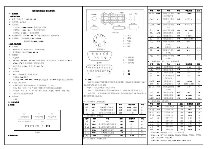
三. 测试仪面板说明测试仪前面板如下图所示:测试仪后面板如下图所示:测试仪面板说明如下:1.显示窗口:分为扭矩、转速、功率三个显示窗口,显示测量值或设置的参数。
状态显示屏:为平面发光二极管透光汉字显示,依次为.“标定”、“设置”、“上限”、“下限”、“正峰”、“负峰”。
扭矩转速功率测试仪说明书扭矩转速功率仪专门配套HCNJ系列动态扭矩传感器使用。
输入信号5-15KHZ和60脉冲/转,可以现场显示扭矩、转速和功率3个参数,并标配清零、扭矩转速两路4-20mA变送、RS485通讯接口等功能。
1基本技术规格●尺寸:A外型盘装160x80x170mm,包括液晶显示和数码管显示2种;T外形台式放置:270x106x220mm。
●液晶显示的仪表,全中文操作界面,设置方便,背光长亮,白天或夜晚都能直观读数,在室外,液晶显示比数码管显示的仪表看的更清楚。
●仪表电源:220VAC功耗:低于15VA●使用环境:-10℃~70℃,湿度0~90%RH,不结露。
●测量分辨率:仪表内部测量分辨率可达1/1000000,显示分辨率受5位显示数码管限制,显示分辩率为1/120000.●测量速度:每秒25次●显示范围:扭矩测量:-99999~99999N.m,显示取绝对值:0~99999N.m,小数点位置可设定转速显示:0~99999,小数点位置可设定功率显示:0~99999,小数点自动调节●脉冲输入信号:各种NPN、PNP、OC门输出的传感器信号、接近开关,旋转编码器131****6023●测量频率:转速脉冲输入0.3Hz ~20KHz扭矩脉冲输入5KHz~15KHz ,可扩展至1HZ~60KHZ●测量刷新频率:每秒30次,适用于快速反应场合。
●标配变送输出✓光电隔离✓2路4mA~20mA 直流电流输出。
输出分辨率:1/4000;误差小于±0.2%F.S,负载能力:小于等于600Ω✓外供电源⏹±15VDC 或24VDC二者选其一,负载能力大于300mA●标配串口通讯√光电隔离√RS232和RS485二者选其一,不指定默认标配RS485串口●可选配串口打印功能,配接标准的的串口打印机,直接支持中文型,中文型打印形式安排可根据客户要求做改动。
2面板及按键说明160x80x170mm 外形面板图台式放置型面板外形270x106x220mm131****6023液晶显示的仪表160x80x170mm名称(针对数码管的仪表)说明显示窗①测量值第一显示窗显示扭矩测量值在参数设置状态下,显示参数符号、参数数值末位小数点闪烁表示峰值显示状态131****6023显示窗②测量值第二显示窗显示转速测量值在参数设置状态下,不显示显示窗③测量值第三显示窗显示功率测量值在参数设置状态下,不显示④指示灯•扭矩报警点的报警状态以及显示峰值标志操作键“设置”键•测量状态下,按住2秒钟以上不松开则进入设置状态•在设置状态下,按一次会显示下一个参数,同时存入上一个参数。