M5U2 Revision
- 格式:ppt
- 大小:256.00 KB
- 文档页数:8
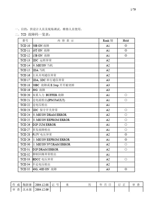
1/79一、目的:供设计人员及现场调试、维修人员使用。
二、TCD 故障码一览表:保存年限:永久版次1.2 作成日期:99.02.05 STE-709-015说明部分:◎:故障排除,主电源开关切OFF-ON后,操作MODE 2清除TCD,方能恢复运转。
○:故障排除,操作MODE 2清除TCD或主电源开关切OFF-ON后,方能恢复运转。
由于MICON系统程式所检查出来的故障,依其重要性可以区分为A~E五种等级(RANK),5/79保存年限:永久版次1.2 作成日期:99.02.05 STE-709-0157/79保存年限:永久版次1.2 作成日期:99.02.05 STE-709-015保存年限:永久版次1.2 作成日期:99.02.05 STE-709-015保存年限:永久版次1.2 作成日期:99.02.05 STE-709-01512/79保存年限:永久版次1.2 作成日期:99.02.05 STE-709-01514/79保存年限:永久版次1.2 作成日期:99.02.05 STE-709-015保存年限:永久版次1.2 作成日期:99.02.05 STE-709-01517/79保存年限:永久版次1.2 作成日期:99.02.05 STE-709-01519/79保存年限:永久版次1.2 作成日期:99.02.05 STE-709-01521/79保存年限:永久版次1.2 作成日期:99.02.05 STE-709-01523/79保存年限:永久版次1.2 作成日期:99.02.05 STE-709-015保存年限:永久版次1.2 作成日期:99.02.05 STE-709-015保存年限:永久版次1.2 作成日期:99.02.05 STE-709-015保存年限:永久版次1.2 作成日期:99.02.05 STE-709-015保存年限:永久版次1.2 作成日期:99.02.05 STE-709-015MPU端子台MPU端子台保存年限:永久版次1.2 作成日期:99.02.05 STE-709-015保存年限:永久版次1.2 作成日期:99.02.05 STE-709-015MPU端子台MPU端子台保存年限:永久版次1.2 作成日期:99.02.05 STE-709-015保存年限:永久版次1.2 作成日期:99.02.05 STE-709-01538/79 39/79保存年限:永久版次1.2 作成日期:99.02.05 STE-709-015保存年限:永久版次1.2 作成日期:99.02.05 STE-709-015保存年限:永久版次1.2 作成日期:99.02.05 STE-709-015保存年限:永久版次1.2 作成日期:99.02.05 STE-709-015。

七年级下册Module 5 Unit 2 London is bigger thanCambridge教学设计一、课标(或大纲)分析本模块以家乡为题材,要求学生理解、掌握本模块材料中关于方位、位置等语言现象。
二、教材分析本次授课内容为外研社New Standard English 七年级下册第五模块第二单元Unit 2 London is bigger than Cambridge. 本单元围绕“My hometown and country.” 这个话题活动展开,通过理解英国一些城市的概况,介绍了方位、形容词的比较级等语言现象,展开口语交际和阅读活动,是一堂阅读课。
本课所学习的内容是基于第一单元的听说练习,学生从简单到复杂,逐步感知新的语言。
三、教学建议分析通过对阅读材料的学习,理解英国的主要城市、河流。
四、教学目标五、教学重点和难点难点;To get information about Cambridge, London and Britain.重点:Key structures:be famous for, in the south of, bigger and busier than,on the River Thames六、主要学习方法及教学策略分析通过学生的自学,简要理解并介绍自己的家乡,学生将新知识融入到自己熟悉的环境中,由简至难,再过渡至不熟悉的英国;通过合作学习策略,注意学习策略共享,教师补充的英国各大城市及河流的内容,对于学生的文化意识有很大的协助。
看听说和动手相结合。
在处理词汇和课文阅读时都采取了看听说,力求使得有不同学习习惯的学生都能够在课堂上找到兴奋点,积极投入到学习活动中。
分组活动。
在实行活动安排或者问题解决时也是按照小组实行任务分担的方式,便于提升学生合作欲望和防止任务过重或者繁复给学生带来倦怠感,也能够利用组内差和组间差调动学生学习积极性和优化学习资源。
设置问题情景,采用问题引导的方式让学生完成阅读。


AN1006: Differences Between Si534x/8x Revision B and Revision D SiliconThis document highlights differences between Revision B and Revision D silicon forthe following part numbers:•Si5340•Si5341•Si5342•Si5344•Si5345•Si5346•Si5347•Si5348•Si5380SUMMARYCompared to Revision B, Revision D silicon for Si534x/8x fixes several errata, supports higher maximum output frequency ranges, and offers several new features. This document outlines those differences.1. Migration from Si534x/8x Revision B to Revision DApplies to Si5380/48/47/46/45/44/42/41/40With the release of Revision D for Si534x/8x, the Revision B devices are now classified as "Not Recommended for New Designs" (NRND). As of the Revision D release date, Silicon Labs has no plans to EOL the Si5348/47/46/45/44/42/41/40 Revision B devices and will continue production of both the Revision B devices and the newer Revision D devices. As of the Revision D release date, Silicon Labs does not plan to continue production of Si5380 Revision B devices. Customers using Si5380 must follow the instructions below to migrate their existing Revision B designs to Revision D.Revision D devices are pin-compatible and footprint-compatible with Revision B devices. However, Revision D devices are not intended to be drop-in replacements for Revision B devices. As a result of changes to the circuitry in Revision D devices, their performance and behavior will not completely match that of Revision B.•Customers currently using Si5348/47/46/45/44/42/41/40 Revision B in production may continue to do so. Silicon Labs will maintain production of both Revision B and Revision D concurrently.•Customers who wish to migrate a design from Revision B to Revision D should download the latest version of ClockBuilder Pro and create a new custom OPN for Revision D with their desired configuration. Once a new Revision D OPN has been created, customers should verify functionality of the device in their system prior to starting production with Revision D.•Silicon Labs does not recommend writing a register file, settings file, or regmap that was created for Revision B to a RevisionD device. When migrating an existing design from Revision B to Revision D, customers should download the latest version ofClockBuilder Pro and create new register files, settings files, or regmap exports to be used with Revision D.1.1 Device Ordering and IdentificationApplies to Si5380/48/47/46/45/44/42/41/40The revision letter which is the 9th digit of the ordering part number indicates "D" for product Revision D. For example: Si5345A-D-GM or Si5345-Dxxxxx-GM, where xxxxx is the custom OPN ID, and D refers to the product revision.1.2 Evaluation Boards Ordering and IdentificationApplies to Si5380/48/47/46/45/44/42/41/40New evaluation boards are available for all Revision D devices. The Revision D evaluation boards are identified with "-D" in the 7th and 8th characters of the OPN. For example, the Si5345 Revision D OPN is Si5345-D-EVB.1.3 Handling Revisions in ClockBuilder ProClockBuilder Pro (CBPro) version 2.9 or later supports both Revision B and Revision D of Si534x/8x. Selection of the target device revision is done in Step 2 of the configuration Wizard:Figure 1.1. Device Revision DThe default revision is "D" for all newly created designs.CBPro stores the target device revision for each project in the .slabtimeproj project file. When an existing project file is opened, CBPro will set the target device revision according to the data stored in the project file.With the NRND classification of Si534x/8x Revision D, CBPro will no longer support creation of new custom ordering part numbers (OPNs) for Revision B. Customers with an ongoing Revision B design who still wish to create custom OPNs for Revision B should contact Silicon Labs.1.4 Changing the Target Device Revision for an Existing CBPro ProjectAt any time the target device revision for a project can be changed in CBPro by choosing Step 2 "Revision" and then selecting the new target revision from the drop-down box at the top of the screen. Customers who have created projects for Revision B in an earlier version of CBPro can migrate their projects to Revision D using the following steps:•Open the original project file in CBPro (CBPro will default to Revision B after opening the file.).•Choose Step 2: "Revision" and select device revision D.•Click the "Finish" button on the lower right side of the screen.When changing a project from Revision B to Revision D in CBPro, note the following:•CBPro will select the default values for any new registers and features that are present in Revision D but were not present in Revision B. This will enable the new Revision D features described below.•CBPro will recalculate the frequency plan using the latest algorithm for Revision D. As a result, the internal frequency plan for Revision D may differ from the plan used on a Revision B project file.Although CBPro will allow the device revision to be changed backwards to Revision D from Revision B, this is not recommended, as Revision D contains several enhancements that are not present on Revision B.AN1006: Differences Between Si534x/8x Revision B and Revision D Silicon • Errata Fixes2. Errata Fixes2.1 Revision B Errata Fixed on Revision D2.2 Revision B Errata Not Fixed on Revision D2.3 Crystal Drive LevelApplies to: Si5380In data sheet rev 0.96 for Si5380 Revision B, the maximum crystal drive level was incorrectly specified as 200 μW. This has been updated to 300 μW for the Si5380 Revision D data sheet and will be corrected in a future release of the Si5380 Revision B data sheet. In addition, the list of approved crystals in the Si5380 reference manual has been updated to reflect this change.AN1006: Differences Between Si534x/8x Revision B and Revision D Silicon • Extended Output Frequency Ranges3. Extended Output Frequency RangesRevision D of Si5345/44/42/41/40 offers higher maximum output frequencies than Revision B. The maximum output frequency for eachNote: Certain limitations apply when output frequencies above 720 MHz are selected. Refer to to the Reference Manual for more information.AN1006: Differences Between Si534x/8x Revision B and Revision D Silicon • New Features and Capabilities4. New Features and CapabilitiesA variety of new features and capabilities are available on Si534x/8x Revision D. These are described in the following sections.4.1 Frequency Ramping on Holdover ExitApplies to Si5380/48/47/46/45/44/42When coming out of holdover, Revision D allows for the adjustment of frequency ramp rate. This greatly minimizes phase transients due to frequency drift while in holdover. The frequency ramp rate adjustment occurs regardless of whether the output frequencies are using fractional or integer synthesis. This feature may be enabledd or disabled in CBPro, and a variety of ramp rates are selectable from 0.2 ppm/s to 40,000 ppm/s.•On Si5380/45/44/42, all outputs will ramp in frequency when the DSPLL is coming out of holdover.•On a Si5348/47/46, only the outputs that connect to the DSPLL that is coming out of holdover will have a ramp in frequency.4.2 Frequency Ramping on an Input Clock SwitchApplies to: Si5380/48/47/46/45/44/42When switching between clock inputs that are not synchronous, Revision D allows for the adjustment of the frequency ramp rate. This greatly minimizes phase transients on the output clocks during the input switching. The frequency ramp rate adjustment occurs regardless of whether the output frequencies are using fractional or integer synthesis. This feature may be enabled or disabled in CBPro, and a variety of ramp rates are selectable from 0.2 ppm/s to 40,000 ppm/s.•On Si5380/45/44/42, all outputs will ramp in frequency when the input clock is switched.•On a Si5348/47/46, when a DSPLL input switch occurs, only the outputs that connect to that DSPLL will have a ramp in frequency. 4.3 Holdover Exit Bandwidth SelectionApplies to: Si5380/48/47/46/45/44/42In Revision D, it is possible to select a PLL bandwidth to be used upon Holdover and Free Run exit. This bandwidth cannot be set to less than the normal bandwidth. The device returns to the normal bandwidth after the PLL has locked.4.4 Loss of Lock Detector ImprovementsApplies to: Si5380/48/47/46/45/44/42/41/40In Revision D, the Si534x/8x LOL detector has been improved to quickly assert LOL on large changes in ppm. Previously on Revision B, a large input frequency change took much longer to assert LOL. The threshold at which LOL is asserted for large ppm changes is set automatically by CBPro based on the frequency plan, and will range from 100 ppm to 1,000,000 ppm.The Si534x/8x Revision D LOL detector has also been improved to detect loss of an input clock signal. On Revision D, if an input clock edge is not detected within 417 μs, LOL will be asserted. Previously on Revision B, loss of an input clock would only trigger LOS and not LOL.4.5 Out of Frequency Detector ImprovementsApplies to: Si5380/48/47/46/45/44/42In Si534x/8x Revision D, the OOF detector has been improved so that OOF is asserted when a loss of signal occurs. Previously on Revision B, the OOF detector would not assert when a loss of signal occurs.Previously on Revision B, either the fast OOF threshold or the precision OOF threshold could be used to both assert and deassert the OOF signal. With Revision D, if the input frequency exceeds either the fast OOF threshold or the precision OOF threshold, OOF will be asserted. However, the input frequency must fall below both OOF thresholds in order for the OOF detector to be deasserted.4.6 Reductions in Output Clock Phase TransientsApplies to: Si5380/48/47/46/45/44/42When performing hitless switching, the output clock phase transient has been reduced in Si534x/8x revision D. New values for this can be found in the data sheet.Additional circuitry optimizes the switching time between Fastlock and normal bandwidth. This reduces output clock phase transients when changing bandwidths.AN1006: Differences Between Si534x/8x Revision B and Revision D Silicon • Changes to Registers from Revision B to Revision D5. Changes to Registers from Revision B to Revision DThe majority of registers present in Si534x/8x Revision B have been left unchanged in Revision D. The exceptions to this are documented below.5.1 Device RevisionApplies to: Si5380/48/47/46/45/44/42/41/40In Si534x/8x the DEVICE_REV register will now read back 0x03 to indicate Revision D. Previously this read back as 0x01 to indicate Revision B.5.2 Preamble and PostambleApplies to: Si5380/48/47/46/45/44/42/41/40In order to change certain registers that affect PLL lock status it is necessary to write a preamble and postamble sequence to the device. The values for the preamble and postamble sequences have changed for Revision D as shown below.Table 5.1. Preamble Sequence for Si5380/47/46/45/44/42/41/40Table 5.2. Postamble Sequence for Si5380/47/46/45/44/42/41/40Table 5.3. Preamble Sequence for Si5348Table 5.4. Postamble Sequence for Si5348Note that on a Revision D device, either the Revision B values or the Revision D values can be written for the preamble/postamble sequence and the device will function the same in either case. However only the Revision D values can be read back from the device.5.3 New Registers Present on Revision DApplies to Si5380/48/47/46/45/44/42/41/40Several new registers have been added to the Si534x/8x Revision D devices to support the new features described above. Details about these new features can be found in the reference manual for each device.Copyright © 2021 Skyworks Solutions, Inc. All Rights Reserved.Information in this document is provided in connection with Skyworks Solutions, Inc. (“Skyworks”) products or services. These materials, including the information contained herein, are provided by Skyworks as a service to its customers and may be used for informational purposes only by the customer. Skyworks assumes no responsibility for errors or omissions in these materials or the information contained herein. Skyworks may change its documentation, products, services, specifications or product descriptions at any time, without notice. Skyworks makes no commitment to update the materials or information and shall have no responsibility whatsoever for conflicts, incompatibilities, or other difficulties arising from any future changes.No license, whether express, implied, by estoppel or otherwise, is granted to any intellectual property rights by this document. Skyworks assumes no liability for any materials, products or information provided hereunder, including the sale, distribution, reproduction or use of Skyworks products, information or materials, except as may be provided in Skyworks’ Terms and Conditions of Sale.THE MATERIALS, PRODUCTS AND INFORMATION ARE PROVIDED “AS IS” WITHOUT WARRANTY OF ANY KIND, WHETHER EXPRESS, IMPLIED, STATUTORY, OR OTHERWISE, INCLUDING FITNESS FOR A PARTICULAR PURPOSE OR USE, MERCHANTABILITY, PERFORMANCE, QUALITY OR NON-INFRINGEMENT OF ANY INTELLECTUAL PROPERTY RIGHT; ALL SUCH WARRANTIES ARE HEREBY EXPRESSLY DISCLAIMED. SKYWORKS DOES NOT WARRANT THE ACCURACY OR COMPLETENESS OF THE INFORMATION, TEXT, GRAPHICS OR OTHER ITEMS CONTAINED WITHIN THESE MATERIALS. SKYWORKS SHALL NOT BE LIABLE FOR ANY DAMAGES, INCLUDING BUT NOT LIMITED TO ANY SPECIAL, INDIRECT, INCIDENTAL, STATUTORY, OR CONSEQUENTIAL DAMAGES, INCLUDING WITHOUT LIMITATION, LOST REVENUES OR LOST PROFITS THAT MAY RESULT FROM THE USE OF THE MATERIALS OR INFORMATION, WHETHER OR NOT THE RECIPIENT OF MATERIALS HAS BEEN ADVISED OF THE POSSIBILITY OF SUCH DAMAGE.Skyworks products are not intended for use in medical, lifesaving or life-sustaining applications, or other equipment in which the failure of the Skyworks products could lead to personal injury, death, physical or environmental damage. Skyworks customers using or selling Skyworks products for use in such applications do so at their own risk and agree to fully indemnify Skyworks for any damages resulting from such improper use or sale.Customers are responsible for their products and applications using Skyworks products, which may deviate from published specifications as a result of design defects, errors, or operation of products outside of published parameters or design specifications. Customers should include design and operating safeguards to minimize these and other risks. Skyworks assumes no liability for applications assistance, customer product design, or damage to any equipment resulting from the use of Skyworks products outside of Skyworks’ published specifications or parameters.Skyworks, the Skyworks symbol, Sky5®, SkyOne ®, SkyBlue™, Skyworks Green™, Clockbuilder ®, DSPLL ®, ISOmodem ®, ProSLIC ®, and SiPHY ® are trademarks or registered trademarks of Skyworks Solutions, Inc. or its subsidiaries in the United States and other countries. Third-party brands and names are for identification purposes only and are the property of their respective owners. Additional information, including relevant terms and conditions, posted at , are incorporated by reference.Portfolio/ia/timingSW/HW/CBProQuality/qualitySupport & Resources/supportClockBuilder ProCustomize Skyworks clock generators, jitter attenuators and networksynchronizers with a single tool. With CBPro you can control evaluationboards, access documentation, request a custom part number, export for in-system programming and more!/CBPro。
Release NotesOriginal InstructionsGuardmaster 440C-CR30 Safety Relay, Revision 11Catalog Number 440C-CR30-22BBBSummary of ChangesThis publication contains the following new or updated information. This list includes substantive updates only and is not intended to reflect all changes.About This PublicationThese release notes supplement the existing documentation supplied with your product. Read this document before using Guardmaster® 440C-CR30 safety relays.Firmware Revision HistoryAvailability of Enhancements and Anomaly FixesEnhancements are available in the safety relay only if it is at the required firmware revision or higher and the Connected Components Workbench™ or Studio 5000 Logix Designer® project contains a safety relay that is configured with the required firmware revision or higher. If the project contains a safety relay revision that is lower than the required revision for an enhancement, then the project is still valid but the enhancement will not be available until the project is upgraded to the minimum supported revision.Fixes for firmware anomalies are available as long as the safety relay firmware revision is at the minimum revision or higher. The configured safety relay revision must be of the same major revision.The following tables provide a list of enhancements, known anomalies, and corrected anomalies for the CR30 safety relay firmware revisions.EnhancementsTopicPage Updated Firmware Revision History 1Updated Table 22Updated image in step 23Revision Description6.004First revision release [safety firmware 0A.01]6.006Minor revision release [safety firmware 0A.02]7.006Major revision release [safety firmware 0A.02]8.013Major revision release [safety firmware 0A.02]9.004Major revision release [safety firmware 0A.02]10.004Major revision release [safety firmware 0A.03]10.009Minor revision release [safety firmware 0A.03]10.010Minor revision release [safety firmware 0A.03]10.011Minor revision release [safety firmware 0A.03]Table 1 - EnhancementsEnhancement (1)DescriptionAvailable From Firmware RevisionLock control function support New Lock Control function is now supported forissuing an unlock request to a safety gate withguard locking.10.004Mode selection function support New Mode Selection Safety Monitoring Function is now supported.10.004Mute function enhancements New Muting function block has been enhanced to support a mute enable input, a mute fault manual monitored reset and now offers a secondary output based on the override status.10.004Status function supportNew Status functions for monitoring andannunciating function block faults or ‘waiting for reset’ conditions.10.004Reusable feedback supportNew ability to apply feedback inputs to multiple Safety Output Functions.10.004Single input And withRestartenhancement New ability for the And with Restart logic function to support one input.10.004PanelView Plus Tag browsing support With release 8.00 of FactoryTalk® View Studio, PanelView™ Plus can communicate to CR30 safety relays using EDS parameter browsing over EtherNet/IP™.9.004Nesting of Logic Level Function blocksNew ability to use the output state of a logic block immediately above another logic block as an input condition.9.004Inverting of Logic Level Inputs/Outputs New ability to invert (logical NOT) of inputs and outputs of Logic Level function blocks.9.004Output Loop Safety Monitoring Function support New Output Loop Safety Monitoring Function that allows the logical state of a Safety Output Function to be used as an input condition.9.004RS Flip-Flop Logic Function support New RS Flip-Flop Logic function is now supported in the Logic level columns of the Logic Editor.9.004440C-ENET plug-in supportThe EtherNet/IP plug-in provides both I/O messaging and explicit messaging. The safety relay can now be configured over EtherNet/IP using either Connected Component Workbench or an Add-on Profile (AOP) in Studio 5000 Logix Designer application.8.013Standard Signal Safety Monitoring Function support New Standard Signal Safety Monitoring Function that allows the use of standard control signals from digital plug-ins or communication ports to be used in the logic of the safety relay.8.013Project Upgrade featureProjects developed for earlier versions of firmware can be automatically converted into the latest version of firmware supported.8.0132080-MEMBAK-RTC plug-in support Project backup and restore are supported on CR30 safety relays through the 2080-MEMBAK-RTC module.7.0062080-IQ4 plug-in supportThe 2080-IQ4 digital input plug-in provides 4-pt standard rated 12/24V DC digital input expansion. It can be used in slot 1 and/or slot 2 module bays.7.0062Rockwell Automation Publication 440C-RN001H-EN-P - December 2020Guardmaster 440C-CR30 Safety Relay, Revision 11 Release NotesAnomalies2080-OB4 plug-in support The 2080-OB4 digital output plug-in provides 4-pt standard rated 12/24V DC sourcing output expansion. It can be used in slot 1 and/or slot 2 module bays.7.0062080-OW4I plug-in supportThe 2080-OW4I relay output plug-in provides 4-pt standard rated relay output, individually isolated, 2A expansion. It can be used in slot 1 and/or slot 2 module bays.7.006Unique function block name supportUnique names can be assigned to the Safety Monitoring Function blocks and the Safety Output Function blocks. These names are stored in the project that is loaded to the safety relay and can be recovered by an upload.7.006Password protection Software connections including Upload, Download,and Connect can be restricted through passwordprotection.7.006(1)For more information, see publication 440C-UM001.Table 2 - Known and Corrected AnomaliesAnomalyDescriptionAffected Firmware Revisions Corrected Firmware Revision Discrepancy Fault on Power-upDevices with pulse testing outputs would sometimes cause a discrepancy fault in the CR30 safety relay upon power-up. On power-up, the Channel Test during the first logic scan when transitioning from self-test to run mode has been removed to help prevent the discrepancy fault.See publication 440C-UM001 for details.6.0046.0067.0068.0139.00410.00410.00910.01010.011Memory Module Incompatibility Safety relay fails to recognize 2080-MEMBAK-RTC memory modules that are manufactured on or after 2016/02/11.APBC000280011 6.0046.0067.0068.0139.00410.00410.00910.010Memory Module Update When updating a safety relay from a previous firmware revision to firmware 10 using thememory module the restore operation must be performed twice (the first process updates thefirmware, the second process restores the user configuration). 6.004 6.0067.0068.0139.004Configuration loss on power cycleDuring specific power down conditions, the safety relay could be interrupted while writing a fault condition to its nonvolatile memory. On power up, the memory is evaluated as corrupted and the user configuration is discarded.APBC00026898 6.0046.0067.0068.0139.00410.00410.009Connection failure with Add-on Profile (AOP) major revision 1The safety relay rejects an I/O connection that originates from the safety relay AOP (versions 1.013 and versions 1.014) when Compatible Keying and Major Revision 8 or later is configured.APBC000271569.00410.004Download faultA download could result in a major fault on the safety relay, Type 06, Code 20 – Configuration Fault.APBC000251087.0068.0139.00410.004Download over Ethernet faultA download over Ethernet to the safety relay could result in a Type 05, Code 00 – Internal Safety Synch Fault.APBC000236608.0139.00410.004Unexpected disconnect from safety relay Occasionally Connected ComponentsWorkbench software would unexpectedly disconnect while connected to a password protected safety relay.APBC000248668.0139.004Table 1 - Enhancements (Continued)Enhancement (1)DescriptionAvailable From Firmware RevisionLocked by another connection error Attempts to connect to the safety relay arerejected and erroneously reports “CR30 has been locked by another, new connection is not allowed.”APBC000248678.0139.004No reconfiguration after EEPROM fault After the safety relay experiences a memory fault (Type 5 Code 00), the safety relay does not accept a new download.APBC00024866 6.0046.0067.0068.0139.004Muting L-Type reports incorrect fault description Under specific configuration conditions, the Muting T Type function block incorrectly reports a mute sensor timing fault when actually a sequence fault occurred.APBC000237318.0139.004Network address changes require power cycle Changes to the 440C-ENET Ethernet portsettings, duplicate IP address detection, and DHCP vs. static IP address settings may require a power cycle to take effect.APBC000241338.0139.004Power-up faultVariations in 24V DC supply power to the CR30 safety relay during power-up could lead to power fault: Type 04, Code 01.APBC000244266.0046.0067.0068.013Discrepancy fault after power-upVariations in 24V DC supply power to the CR30 safety relay during power-up could lead to adiscrepancy fault on any dual channel Safety Monitoring Function: “One channel open after reset” 6.0046.0067.0068.013Empty fault logModbus reporting of the fault log always returns 0, indicating no fault, even if faults are present in the log.APBC00025011 6.0046.0067.0068.013Incorrect Mode The safety relay will return to Run Mode after downloading a valid configuration to a unit that has experienced a nonrecoverable fault.APBC000257716.0046.0067.0068.013Modbus fault state cleared in Program Mode The safety relay does not report faultinformation over Modbus once the safety relay is placed in Program Mode.6.0046.0067.0068.013Memory module firmware update failure The memory module is unable to upgrade a firmware revision 7 safety relay to version 8 or later 7.006L-Type muting override conditionOverride for L-Type muting cannot be initiated when only the light curtain is interrupted (no mute sensors).6.0046.0067.006Two Hand Control at power up Two Hand Control does not fault at power up if buttons are pressed. 6.0046.0067.006Override conditionsFor muting applications, mute sensor interrupted or timing faults should be only conditions that allow override to be initiated.6.0046.0067.006Serial port doesnot shutdownWhen the serial port is configured as shutdown,it still responds to Modbus messages.APBC00020590 6.0046.0067.006Input filters greater than 200 ms create nonrecoverable fault When an input filter of greater than 200 ms is configured on any Safety Monitoring function, a nonrecoverable fault is generated when the configuration is downloaded to the safety relay.APBC00020589 6.0046.0067.006Missing plug-in slot 1 without fault log entry A missing plug-in module configured in slot 1 and not actually present results in a fault but no fault log entry is created.APBC00018493 6.0046.0067.006Plug-inmismatch with duplicate fault log entriesA mismatch between the plug-in present on slot 1 and the actual plug-in present results in duplicate entries in the fault log.APBC000205086.0046.0067.006Plug-in outputs fail to configure When Plug-in outputs terminals are selected asoutputs for Safety Output Functions, they fail toturn on when the corresponding Safety OutputFunction turns on.APBC000201036.004 6.006Table 2 - Known and Corrected Anomalies (Continued)AnomalyDescriptionAffected Firmware Revisions Corrected Firmware RevisionRockwell Automation Publication 440C-RN001H-EN-P - December 20203Guardmaster 440C-CR30 Safety Relay, Revision 11 Release NotesUse DMK FilesFirmware for the CR30 safety relay beginning with firmware revision 10.009 uses a new file format called *.DMK. These files are named for easy identification, for example: 440C-CR30-22BBB_10.009.dmk.ControlFLASH™ software, version 13 or later, supports the format. ControlFLASH software is automatically installed as part of Studio 5000 Logix Designer application installation, version 28 or later. You can download ControlFLASH software from the Rockwell Automation Product Compatibility and Download Center (PCDC - rok.auto/pcdc ) separately, if necessary.You are not required to install the new firmware file format. When you download *.DMK files from the Rockwell Automation PCDC, ControlFLASH softwareautomatically saves the folder location where the *.DMK files were downloaded. As a result, ControlFLASH software can easily locate *.DMK files.You can use the Browse option to access and configure the folders that ControlFLASH software monitors as shown:Upgrade Safety Relay FirmwareThis procedure shows you how to update the firmware in a CR30 safety relay using ControlFLASH. To download the latest CR30 safety relay firmware revision, go to the PCDC (PCDC - rok.auto/pcdc ) and select your desired revision.On CR30 safety relays, you can upgrade your safety relays through the Ethernet port on the 440C-ENET plug-in module and the USB.Through USB1.Verify successful RSLinx® Classic communications with you CR30 safety relay by USB using RSWho. The CR30 safety relay uses the AB_VBP-x driver.2.Start ControlFLASH (Start > All Programs > FLASH Programming Tools > ControlFlash) and click Next >.3.Select the catalog number of the CR30 safety relay (440C-CR30-22BBB) that you are updating and click Next >.4.Select the safety relay in the browse window and click OK.Communication fault without fault log entryIf the host microprocessor within the CR30safety relay loses communication with the safety processors a fault is generated but no fault log entry is createdAPBC00020302 6.0046.006Fault log index changes after power cycleAfter a power cycle of the safety relay,previously detected faults index by one within the fault log.APBC000186376.004 6.006Inverted image of downloadprogram notcompared After performing a download, the inverted datais sent back from the safety relay to Connected Components Workbench software but not compared as an additional diagnostic check.APBC00020430 6.004 6.006Download through virtual image failsDownload of a program to the safety relay occasionally fails due to connection timeout when downloading through a virtual image.6.004 6.006ATTENTION: All Ethernet settings are reverted to factory default after a ControlFLASH firmware update.Table 2 - Known and Corrected Anomalies (Continued)AnomalyDescriptionAffected Firmware Revisions Corrected Firmware Revision IMPORTANTTo update your safety relay successfully, it must be in Program Mode or BOOT Loader mode. The safety relay can be placed into Program Mode from the Graphic Overview screen in Connected Component Workbench software, the Logic Configuration tab in the Logix Designer module profile or placed in BOOT Loader mode by holding the MEM/ID button located below the USB port on the safety relay during power-up.Publication 440C-RN001H-EN-P - December 2020 | Supersedes Publication 440C-RN001G-EN-P - April 2016Copyright © 2020 Rockwell Automation, Inc. All rights reserved. Printed in the U.S.A.Rockwell Otomasyon Ticaret A.Ş. Kar Plaza İş Merkezi E Blok Kat:6 34752 İçerenköy, İstanbul, Tel: +90 (216) 5698400 EEE Yönetmeliğine UygundurAllen-Bradley, Connected Components Workbench, ControlFLASH, expanding human possibility, FactoryTalk, Guardmaster, PanelView,Rockwell Automation, RSLinx, and Studio 5000 Logix Designer are trademarks of Rockwell Automation, Inc.EtherNet/IP is a trademark of ODVA, Inc.Trademarks not belonging to Rockwell Automation are property of their respective companies.Your comments help us serve your documentation needs better. If you have any suggestions on how to improve our content, complete the form at rok.auto/docfeedback .For technical support, visit rok.auto/support.Waste Electrical and Electronic Equipment (WEEE)Rockwell Automation maintains current product environmental compliance information on its website at rok.auto/pec .At the end of life, this equipment should be collected separately from any unsorted municipal waste.5.Verify the revision, and click Next > to continue.6.Click Finish.7.Click Yes to initiate the update.The next screen shows the download progress.If you see the following error message, verify that the safety relay is in Run mode. If so, change to Program or BOOT Loader mode by pressing theMEM/ID switch during power-up of the CR30 safety relay, click OK, and try again.When the update is complete, you see a screen similar to the following.Click OK to complete the update.。