衬氟隔膜阀使用说明书
- 格式:pdf
- 大小:239.18 KB
- 文档页数:5
G41F46-10C衬氟隔膜阀
详细介绍
G41F46-10C衬氟隔膜阀的产品类型是隔膜阀.
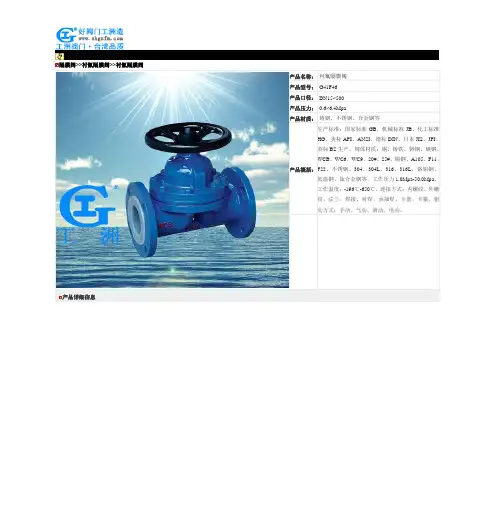
衬氟隔膜阀(G41F46、G641F46、G45F46)
品牌:KT
品名:衬氟隔膜阀G41F46-10C
型号:G41F46-10C
产地:天津
该产品采用特殊工艺在阀体上包衬聚四氟乙烯,隔膜件采用聚四氟乙烯和隔膜内衬丁腈橡胶衬垫,使阀门内腔的各个零部件达到相同的耐腐蚀性能。
该产品具有良好的节流特性,耐腐蚀性和抗颗粒介质性,密封性能可靠,可广泛应用于各种腐蚀性流体以及纤维状、粉末状介质。
衬里材料:PTFE(F4)、FEP(F46)、PFA、PO等。
适用介质:硫酸、氢氟酸、磷酸、氯气、强碱、王水等具有强腐蚀性的介质。
设计标准:HG/T3704
结构长度:GB/T12221-1989、ANSI B16.10
法兰标准:JB/T79-1994、GB/T9113.1-2000、ASME/ANSI 16.5a
公称压力:0.6、1.0、1.6Mpa、Class150、300Lb
检验试验:GB/T9092-1989、API589
驱动方式:手动、电动、气动等操作方式。
本公司还供应上述产品的同类产品:碳钢隔膜阀,卫生级隔膜阀,不锈钢隔膜阀相关链接:/fmgmf/17369.shtml。
上海阀门五厂气动隔膜阀说明书
一、产品概述
上海阀门五厂气动隔膜阀是一种特殊设计的阀门,它结合了气动执行器和隔膜的结构特点,具有高效、安全、可靠等优点。
广泛应用于化工、环保、水处理等领域,是一种理想的控制设备。
二、产品特点
1. 气动执行器采用压缩空气为动力,可实现快速启闭,操作简便。
2. 隔膜材料具有良好的耐腐蚀性能,能够有效防止介质渗漏。
3. 阀体结构紧凑,安装方便,维护简单。
4. 可根据客户需求定制不同规格和材质的阀门。
三、使用注意事项
1. 使用前应检查阀门是否符合使用要求,确认产品合格后再投入使用。
2. 使用过程中应保持清洁,定期进行维护保养,发现异常应及时处理。
3. 气动执行器应使用干燥、清洁的压缩空气,避免杂质和水分对阀门造成损坏。
4. 在使用过程中,应避免阀门受到过大的外力和压力,以免损坏阀门结构。
5. 阀门应安装在干燥、通风良好的地方,避免潮湿和腐蚀环境。
四、常见故障及排除方法
1. 阀门无法关闭:检查气动执行器是否正常工作,阀芯是否有异物卡住,如有需要清理或更换阀芯。
2. 阀门泄漏:检查隔膜是否破损或老化,如有需要更换隔膜;检查阀座是否松动或损坏,如有需要紧固或更换阀座。
3. 执行器动作缓慢或不动作:检查压缩空气是否正常供应,气源压力是否符合要求;检查执行器是否有故障或堵塞,如有需要维修或更换执行器。
隔膜阀基本操作步骤
①带有旁通的丝扣隔膜阀在开启前应先打开旁通阀(以平衡进出的差压、减小开启力矩)。
②操作时,人体不能正对阀杆顶部,以防阀杆受压喷出伤人。
③开关操作要平稳、用力咬均匀,严禁使用冲击力,一般情况用手操作即可,避免使用加工杠杆操作新阀。
④手轮(手柄)强度的设计是以操作所需的扭力值为参考依据的,因此不可将手轮(手柄)当做操作踏板及任意增长或套接加长杠杆,或以扳手来过度增加扭力,不能使用绳索等作用在手轮(手柄)上,再以起重机或滑轮来操作或吊运阀门。
⑤带手轮或手柄的隔膜阀,顺时针转动手轮为关,逆时针转动为开。
当阀门全开后,应将手轮反方向回转1-2圈。
带有其他执行机构的丝扣闸阀的操作方式应严格遵循产品说明书。
⑥高压差下,闸板半开半关状态下易损坏闸板,因此丝扣闸阀不能用于节流或调节,须一次性开启或关闭。
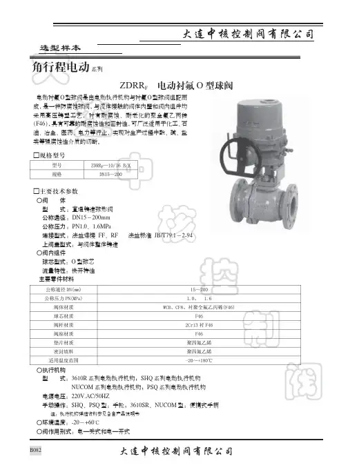
大连中核控制阀ZDRR F 电动衬氟O 型球阀选型样本大连中核控制阀有限公司系列角行程电动电动衬氟O 型球阀是由电动执行机构与衬氟O 型球阀组配而成,是一种防腐蚀球阀,与流体接触的阀体内壁和阀内组件均采用高压铸塑工艺,衬有耐腐蚀、耐老化的聚全氟乙丙稀(F46),具有可靠的耐腐蚀性和密封性,可广泛适用于化工、石油、冶金、医药、电力等行业,实现对生产过程中酸、碱、盐类等强腐蚀性介质的切断。
□规格型号□主要技术参数○阀 体 型 式:直通铸造球形阀 公称通径:DN15~200mm 公称压力:PN1.0、1.6MPa 连接型式:法兰连接 FF 、RF 法兰标准 JB/T79.1~2-94 上阀盖型式:与阀体整体铸造○阀内组件 球芯型式:O 型球芯 流量特性:快开特性 主要零件材料○执行机构型 式:3610R 系列电动执行机构;SHQ 系列电动执行机构 NUCOM 系列电动执行机构;PSQ 系列电动执行机构电源电压:220V.AC/50HZ手动操作:SHQ 、PSQ 型:手轮;3610SR 、NUCOM 型:便携式手柄注:执行机构详细资料参见各自产品说明书○环境温度:-20~+60℃○阀作用刑式:电—关式和电—开式大连中核控制阀□主要技术参数○泄 漏 量:小于10-8×阀额定容量○基本误差:3610R 执行机构为±1%;SHQ 、NUCOM 执行机构为±1.5%;PSQ 执行机构为±1%○回 差:3610R 执行机构为1%;SHQ 、NUCOM 执行机构为1.5%;PSQ 执行机构为1%○死 区:0.5%○可调范围:200∶1○额定行程:90°□额定流量系数Kv 值、执行机构配置、允许压差△P 注:NUCOM 电动执行机构为调节式,两位式为UNIC ○流量特性曲线快开特性□外形尺寸 配3610R 执行机构 配SHQ 执行机构 配NUCOM 执行机构 配PSQ 执行机构连中核控制 阀连中核控 制阀 注:重量为PN1.0MPa 的阀□订货须知1、产品型号2、公称通径3、公称压力4、阀体和阀内组件材料5、执行机构型号6、阀作用形式(电—关式还是电—开式)订 货 说 明7、介质名称、温度和密度 8、介质粘度,是否含有悬浊液 9、正常流量和要求最大流量10、介质压力,最大流量和最小流量时 的进口压力和出口压力11、特殊要求。
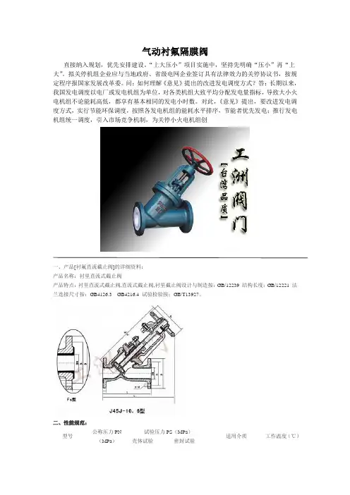
气动衬氟隔膜阀直接纳入规划,优先安排建设。
“上大压小”项目实施中,坚持先明确“压小”再“上大”。
拟关停机组企业应与当地政府、省级电网企业签订具有法律效力的关停协议书,按规定程序报国家发展改革委。
问:如何理解《意见》提出的改进发电调度方式?答:长期以来,我国发电调度以电厂或发电机组为单位,对各类机组大致平均分配发电量指标,导致大小火电机组不论能耗高低,都享有基本相同的发电小时数。
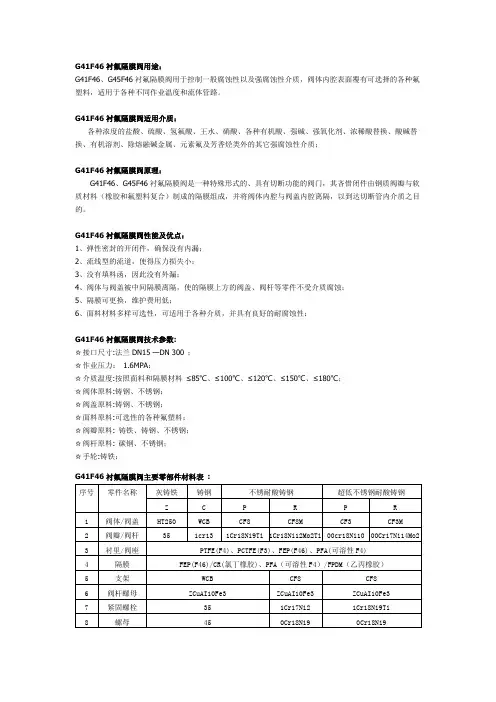
对此,《意见》提出,要改进发电调度方式,实行节能环保调度,按照各发电机组的能耗水平排序,节能者优先发电;推行发电机组统一调度,引入市场竞争机制,为关停小火电机组创一、产品[衬氟直流截止阀]的详细资料:产品名称:衬里直流式截止阀产品特点:衬里直流式截止阀,直流式截止阀,衬里截止阀设计与制造按:GB/12239 结构长度:GB/12221 法兰连接尺寸按:GB4126.3GB4216.4 试验检验按:GB/T13927。
二、性能规范:型号公称压力PN(MPa)试验压力PS(MPa)适用介质工作温度(℃)壳体试验密封试验J45J/FS-6 0.6 0.9 0.66 W.非腐蚀性流体 J.一般腐蚀性流体 FS.强酸碱及各种有机溶剂(溶融碱金属及元素氟除外)≤85 ≤150J45J/FS-10 1.0 1.5 1.1三、主要零部件材料表:零件名称 阀体、阀瓣 阀盖阀杆、阀瓣 手轮廓 材料HT200衬氟塑料、衬橡胶HT200衬氟塑料、衬橡胶35衬氟塑料衬橡胶HT200四、工洲牌衬氟直流截止阀主要连接尺寸及重量:型号公称通径DN (mm ) 尺寸(mm )质量(kg ) L D D1 D H1 b Do n-d 25 160 100 75 60 205 16 120 4-11 4.5 32 180 120 90 70 - 16 160 4-13.5 13 40 200 130 100 80 250 16 160 4-13.5 14 50 230 140 110 90 290 16 160 4-13.5 16.5 65 290 160 130 100 310 16 180 4-13.5 80 310 190 150 125 358 18 200 4-17.5 36 100 350 210 170 145 428 18 200 4-17.5 50 125 400 240 200 175 510 20 280 8-17.5 68 150 480 265 225 200 550 20 280 8-17.5 90 200 600 30 280 255 635 22 400 8-17.5 1462507303753353122412-.17.5一、产品[衬氟直角截止阀]的详细资料: 产品型号:J44J/FS 型产品名称:衬里直角阀产品特点:公称通径:DN15~300(mm)主要零部件材料见表A2 基本型号:手动J44F43 电动J944F3 J44F46 J944F46 法兰连接截止阀(角式)设计与制造符合中国国家标准基本结构形式:角式公称压力:PN1.0~2.5(MPa)法兰连接手动截止阀,角式截止阀,手动截止阀。
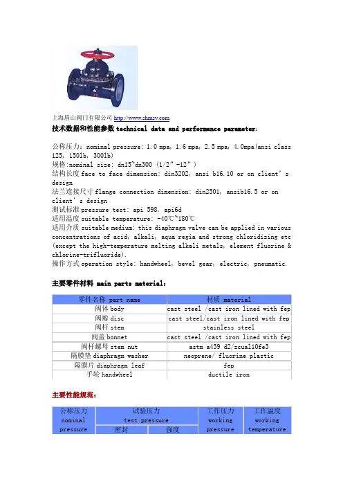
G41F46衬氟隔膜阀用途:G41F46、G45F46衬氟隔膜阀用于控制一般腐蚀性以及强腐蚀性介质,阀体内腔表面覆有可选择的各种氟塑料,适用于各种不同作业温度和流体管路。
G41F46衬氟隔膜阀适用介质:各种浓度的盐酸、硫酸、氢氟酸、王水、硝酸、各种有机酸、强碱、强氧化剂、浓稀酸替换、酸碱替换、有机溶剂、除熔融碱金属、元素氟及芳香烃类外的其它强腐蚀性介质;G41F46衬氟隔膜阀原理:G41F46、G45F46衬氟隔膜阀是一种特殊形式的、具有切断功能的阀门,其吝惜闭件由钢质阀瓣与软质材料(橡胶和氟塑料复合)制成的隔膜组成,并将阀体内腔与阀盖内腔离隔,以到达切断管内介质之目的。
G41F46衬氟隔膜阀性能及优点:1、弹性密封的开闭件,确保没有内漏;2、流线型的流道,使得压力损失小;3、没有填料函,因此没有外漏;4、阀体与阀盖被中间隔膜离隔,使的隔膜上方的阀盖、阀杆等零件不受介质腐蚀;5、隔膜可更换,维护费用低;6、面料材料多样可选性,可适用于各种介质,并具有良好的耐腐蚀性;G41F46衬氟隔膜阀技术参数:☆接口尺寸:法兰DN15 —DN 300 ;☆作业压力:1.6MPA;☆介质温度:按照面料和隔膜材料≤85℃、≤100℃、≤120℃、≤150℃、≤180℃;☆阀体原料:铸钢、不锈钢;☆阀盖原料:铸钢、不锈钢;☆面料原料:可选性的各种氟塑料;☆阀瓣原料: 铸铁、铸钢、不锈钢;☆阀杆原料: 碳钢、不锈钢;☆手轮:铸铁;G41F46衬氟隔膜阀主要零部件材料表:序号零件名称灰铸铁铸钢不锈耐酸铸钢超低不锈钢耐酸铸钢Z C P R P R 1阀体/阀盖HT250WCB CF8CF8M CF3CF3M 2阀瓣/阀杆351cr131Cr18Ni9Ti1Cr18Ni12Mo2Ti00cr18Ni1000Cr17Ni14Mo2 3衬里/阀座PTFE(F4)、PCTFE(F3)、FEP(F46)、PFA(可溶性F4)4隔膜FEP(F46)/CR(氯丁橡胶)、PFA(可溶性F4)/FPDM(乙丙橡胶)5支架WCB CF8CF86阀杆螺母ZCuAI10Fe3ZCuAI10Fe3ZCuAI10Fe37紧固螺栓351Cr17Ni21Cr18Ni9Ti8螺母450Cr18Ni90Cr18Ni99手轮WCB WCB WCBG41F46衬氟隔膜阀技术规范:设计标准GB12239结构长度JB1688/GB12221法兰标准JB/T79-94GB9113.1-26检验试验GB/T13927驱动方式手动、电动、气动、常闭型、常开型G41F46衬氟隔膜阀结构图:G41F46衬氟隔膜阀连接尺寸:公称通径标准值参考值DN(mm)NPS(inch)L D D1D2f b Z-фd d0H H1WT(kg)PN0.6MPa / PN1.0MPa151/21259565452144-ф14100105110 3.5 203/413510575552164-ф141001151254 25114511585652164-ф14120120135 5.5 3211/4160135100782184-ф181201251508 4011/2180145110853184-ф1814013517511 5022101601251003204-ф1814015519514 6521/22501801451203204-ф1820017020023 8033001951601353224-ф1820020025529 10043502151801553228-ф1828027032546 12554002452101853248-ф1832033540570 15064602802402103248-ф2332037045095 20085703352952653268-ф23400480600170 2501068039035032032812-ф23500545620270 3001279043539536242412-ф23500585680320PN1.6MPa151/21309565452144-ф141201101154 203/415010575552164-ф141201201305 25116011585652164-ф141401251406 3211/4180135100782184-ф181401301559 4011/2200145110853184-ф1816014018012 5022301601251003204-ф1816016020015 6521/22901801451203204-ф1820017520524 8033101951601353228-ф1820020526030 10043502151801553248-ф1828027533048 12554002452101853268-ф1832034041075 15064802802402103288-ф23320375460105 200860033529526533012-ф23400485605182 2501073040535532033212-ф25500550625295 3001285046041037543412-ф25500590685345。
隔膜阀的基本操作①隔膜阀阀带有旁通的闸阀在开启前应先打开旁通阀(以平衡进出的差压、减小开启力矩)。
②隔膜阀操作时,人体不能正对阀杆顶部,以防阀杆受压喷出伤人。
③隔膜阀开关操作要平稳、用力咬均匀,严禁使用冲击力,一般情况用手操作即可,避免使用加工杠杆操作新阀。
④隔膜阀手轮(手柄)强度的设计是以操作所需的扭力值为参考依据的,因此不可将手轮(手柄)当做操作踏板及任意增长或套接加长杠杆,或以扳手来过度增加扭力,不能使用绳索等作用在手轮(手柄)上,再以起重机或滑轮来操作或吊运阀门。
⑤带手轮或手柄的隔膜阀,顺时针转动手轮为关,逆时针转动为开。
当阀门全开后,应将手轮反方向回转1-2圈。
带有其他执行机构的闸阀的操作方式应严格遵循产品说明书。
⑥高压差下,闸板半开半关状态下易损坏闸板,因此闸阀不能用于节流或调节,一次性完全开启或完全关闭。
隔膜阀阀可以安装在任意角度的管道上,但不宜倒装,通常可侧立式或卧式安装,以防止管道中杂质在密封面上滞留。
隔膜阀阀蝶板的开度与流量基本呈线性比例变化,如果用作控制节流,当节流幅度较大时,蝶板的背面易发生气蚀,有损坏阀门的可能,故蝶板开度不宜太小,一般要求其开度应大于15°。
当蝶板处于中间开度时,水流动力矩会起作用,故操作机构需加自锁功能。
隔膜阀阀安装时应使阀门处于关闭状态,以防阀体变形。
特别要防止焊接管道或法兰时焊渣掉在密封面上,以确保阀门严密性。
系统作水压试验时,中线沟槽蝶阀应处于开启状态。
隔膜阀阀在存放和保管期间应使蝶板开启4°~5°,以防止密封圈产生疲劳变形。
隔膜阀阀的蝶板进口侧装有弯头时,会形成偏流,蝶板开闭力矩会增大,故要求蝶板与弯头间应有不小于4倍管径的距离。
隔膜阀的密封原理是靠楔形闸板上的两密封面和阀体上的两密封面楔入时的紧密结合来达密封的。
使用楔形闸板的目的是为了提高辅助的密封载荷,以使金属硬密封沟槽闸阀既能对高介质压力,也能对低介质压力进行密封。
ITT RICHTER CHEMIE-TECHNIK The Answer to Corrosion Series MV/MVPOperating Manualfor Diaphragm ValvesContents1General2Safety3Transport and storage4Product description5Installation6Operation7Maintenance8Faults9Tables, diagrams,drawingsTotal No. of pages: 7Local agent:See orderReprinting is generally permittedindicating the source.However, our prior written consentmust be obtained in all cases.Note:This operating manual must be strictly observed TM 4055 en Edition 4/00before transport, installation, commissioning etc.Version 1.01GeneralRICHTER valves correspond to the technical delivery conditions for valves as per DIN 3230.The operating manuals enclosed for the accessories must also be carefully read and observed.1.1ApplicationThe corrosion-resistant fluoroplastic lining of the valves makes them ideally suited for aggressive media.Information concerning the operational conditions of the valve is contained in Section 9.If the valve is to be used for operational data other than those intended, the customer has to carefully consider whether the valve, accessories and materials are suitable for the new application.1.2Product dataType codeDiaphragm valve,hand-operated:MV/....Diaphragm valve,remote actuation:MVP/...with liningPFA/PTFE:....../F DN 15 - 100PFADN 125 - 200PTFE PVDF:....../V DN 15-50PP:....../P DN 15-50Nominal sizes:15, 20, 25, 32, 40, 50, 65, 80, 100, 125,150, 2002SafetyPeople may be at risk if this general hazardsymbol is not observed.If this safety sign is not observed, the valvemay be damaged and its function impaired.2.1Staff qualifications and trainingThe staff for installation, operation and maintenance must have the appropriate qualifications for this work.The area of responsibility, authority and supervision of the staff must be regulated precisely by the customer.If the staff do not have the necessary know-how, they are to be trained and instructed.This can, if necessary, be performed by the manufacturer / sup-plier on behalf of the valve customer.Furthermore, the customer must ensure that the contents of the operating manual are fully understood by the staff.2.2 Risks if safety notes are not observedThe non-observance of the notes on safety can result in the loss of any rights to claims for damages.Non-observance may, for example, result in the following hazards:•Failure of important functions of the valve / plant.•Endangering personnel by electrical, mechanical and chemicalinfluences.•Endangering the environment through leakage of hazardous media.2.3Safety-conscious workingThe following are to be observed:•The notes on safety in this operating manual.•The national accident prevention regulations.•The work, operating and safety regulations of the customer. 2.4Notes on safety for the customer/operator•If hot or cold components of the valve are a source of danger, the customer must protect these components from being touched.•No protective facilities may be removed when the valve is in operation.2.5Notes on safety for maintenanceWork on remotely actuated valves is only to be carried out when they are at a standstill.Valves which deliver harmful media must be decontaminated.On completion of work, all safety and protective equipment must be immediately refitted or re-activated.Before re-starting, attention has to be paid to the instructions in the section "Initial commissioning".2.6Conversion work and production of spareparts by the customerConversion of or changes to the valve are only admissible after consultation with the manufacturer.Original spare parts and accessories authorised by the manufac-turer serve to enhance safety.The use of other parts may annul the liability for any resultant consequences.2.8Inadmissible modes of operationThe operational reliability of the valve supplied is only guaranteed when used in accordance with Section 1 of this operating manual.CAUTION !3Transport and storageIt is imperative for all transport work to observegenerally accepted engineering practice and theaccident prevention regulations.3.1UnpackingImmediately after unpacking, the consignment is to be checked for completeness and any in-transit damage.3.2TransportThe goods have to be handled with care to prevent damage. Flange covers serve as transport protection and must not be removed.3.3StorageIf the valve is not to be installed immediately on delivery, it must be properly stored.It should be stored in a dry room at as constant a temperature as possible.Storage over a prolonged period may necessitate moisture-proof packaging. A decision on this must be taken on the basis of the local conditions.3.4 Return consignmentsThe customer must ensure that the valves havebeen well flushed and cleaned before beingpassed on to the maintenance staff. This is ofparticular importance when the goods are returnedto the manufacturer.3.4.1GRAS certificateA GRAS certificate according to EUROPUMP on the field of application is to be enclosed with the returned goods.If necessary, safety precautions and decontamination measures are to be mentioned.Pre-printed forms can be requested from ITT Richter.4Product descriptionThe entire diaphragm valve is of a simple design. In comparison to conventional full-bore valves, it has the advantage that, apart from the diaphragm, the one-piece body is the only "wetted" part.The valves are protected against aggressive atmospheres on the outside with an epoxy paint.Richter diaphragm valves consist of the assemblies:- Body- Upperpart4.1BodyThe metallic body bears the following cast data as per DIN EN 19:− nominal diameter− nominal pressure− body material− manufacturer's code−melt number / foundry number− lining material4.2Upper partThe upper part of the diaphragm valve consists of the bonnet, compressor, diaphragm, stem/valve stem, threaded bushing, (stroke index), travel stop (DN 15 - 80), position indicator (DN 100– 200) and handwheel.4.3NameplateA nameplate on the body contains the following details :- RichterproductionNo.- Any customer-specific dataExample of production No.: 99 4875/2/1Please indicate the production number on all correspondence.5 InstallationTo protect the sealing surfaces againstcontamination and damage, the yellowprotective caps must remain on the flanges until just before installation.The plant must be flushed and free of loose solid matter.The installation space must correspond to the face to face dimen-sion.We recommend gaskets to protect the sensitive plastic sealing surfaces against damage by the mating flange.Gaskets with a PTFE jacket and a stainless steel inlay must be used if a flange is endangered by hard pipe flanges, e.g. made of metal or ceramic.The size of the gaskets must correspond to the nominal diameter of the valve.5.1Direction of flowThe direction of flow is not prescribed for diaphragm valves. The direction can be determined as required.5.2EarthingIf the valve has to be earthed, this can also be performed using the pipe screws.A tooth lock washer is placed under one nut of each valve flange. This penetrates the paint film and thus creates the electric contact with the screw.5.3 Tightening torques of the screw fittingsTighten the connection screws between thebonnet and body with a torque wrench.For recommended torques for the screws, see Section 9.6.CAUTION !CAUTION !6Operation6.1Initial commissioningNormally the valves are tested for leaks with water and air. Unless other agreements have been made, there may still be residual amounts of water in the bore of the valve. Beware of a possible reaction with the operating medium.After initial loading of the valve with operating pressure and tem-perature, the torques of all connection screws must be checked.6.2ShutdownIf the valve is to be dismantled, the local regula-tions are to be observed.Always make sure that the pipe and the vessel have been depressurised and emptied.Suitable protective action is to be taken to avert any risk to people and the environment throughany aggressive or toxic media leaking.If the dismantled valve is to be returned to the company's own workshop or to the manufacturer, it must be thoroughly cleaned.See also Section 3.4.After dismantling, immediately protect the plastic flanges of the valve against mechanical damage using flange caps.6.3Re-startingWhen re-starting the valve, make sure that, depending on the progress of shutdown, all the appropriate steps as described in Section 5 and Section 6.1 are repeated.6.4Inadmissible modes of operation and their consequencesWhen operating in the range of below-zero temperatures, the national regulations are to be observed.7 Maintenance• Check all connection screws of the valve in accordance withSection 5.3.• Check the working order of all other equipment in accordancewith the plant standards in the operating area:− body screws− safety stuffing box − air connections − control equipment − protective devices − etc.The exact arrangement and designation of all single parts belong-ing to the valve including the item numbers mentioned in the following instructions are contained in the arrangement drawing in Section 9.9.All maintenance work is to be performed with appropriate tools by qualified staff. The working practice applicable in the general mechanical engineering sector is to be observed.7.1Screw connectionsPeriodical checks of the tightening torques in line with the opera-tional requirements at the following points:•Connection screws between body and bonnet.•Pipe screws .For tightening toques, see Section 9.6.7.2CleaningThe valve is to be cleaned thoroughly before the start of repair work. Even if the valve has been properly drained and flushed, there could still be residual amounts of medium in the valve, e.g.between the sealing surfaces.Moreover, the plastic components may have absorbed medium which emerges gradually from the material after cleaning.Protective clothing should therefore be worn.See also Section 3.4.7.3Dismantling7.3.1MV (with handwheel)− Undo cover screws and remove upper part.− Turn stem into the threaded bushing until the compressor withthe diaphragm is exposed.− Turn diaphragm through 90° and lift off (bayonet catch).Observe safety regulations when working with the medium.When cleaning, do not treat mechanically but only use soft and/or liquid cleaning materials.7.3.2MVP (with actuator)-Open coupling and remove actuator.- Press stem into the bushing until the compressor with thediaphragm is exposed.-Turn diaphragm through 90° and lift off (bayonet catch).7.4Assembly-Insert new diaphragm, turn through 90° (bayonet catch). Then perform tensile test to see whether the bayonet catch has en-gaged.-Turn stem (manual activation) upwards into the threaded bushing. / Press valve stem (remote activation) upwards in the bushing.-Mount upper part on the body and tighten screws to a torque in accordance with Section 9.6. in diametrically opposite se-quence.7.4.1MV (with handwheel)The travel stop is set as follows with DN 15-80 :-Close valve until completely tight.- Screw travel stop onto stem until in contact with threadedbushing.- Mount handwheel onto stem and find the best position be-tween the stem square feature and the finger on the travel stop; if necessary, turn the stem slightly to the left or right.CAUTION !CAUTION !- The position indicator is set as follows withDN 100-200 :- Close valve until completely tight.- Screw position indicator onto stem up to the end of the yellow paint on the threaded bushings.- Mount handwheel onto the stem and find the best position between the stem square feature and the finger on the travel stop. If necessary, turn the stem slightly to the left or right.- Mount handwheel with intermediate ring onto the stem.7.4.2MVP (with actuator)Mount bracket, groove nut, travel stop, protective bellows and coupling.Mount actuator and close coupling.Close valve until completely tight.Turn travel stop fully tight and counterlockMount protective bellows and hose clip.7.5TestsAll points cited in Section 6.3 are to be observed. After assembly of the valve, a leak test must be performed.8Faults•In case of leaks between the bonnet and body, tighten the screws in accordance with the torques in Section 9.6.•In case of leaks between the stem and threaded bushing or between the bonnet and threaded bushing, the diaphragm is defective. Replace the diaphragm in accordance with Section7.3.•If valves have been opened for operational or other reasons, the diaphragm must always be replaced with a new one. It is possible that the sealing surface of the body has to be care-fully reworked in order to prevent leaks after assembly and re-starting.9Tables, diagrams, sectional drawings9.1 Connectiondimensions- Face to face:see order- Flange pattern:see order- Actuator:seeorder9.2Parts subject to wear- Diaphragm9.3Nominal pressureDN 15- 50PN 16DN 65-200PN 10See Section 9.79.4Weights (with handwheel)DN kg15 2.820 3.425 4.332 6.1408.45011.06515.08020.010031.012543.015067.0200136.09.5Flow ratesDN Kv100-valuem3/h157.82010.02515.03222.54037.05065.06595.080134.0100200.0125320.0150452.0200650.09.6Tightening torquesLubricate screws, tighten in diametrically opposite sequence Pipe screwsDN No. x size[Nm]15/20 4 x M12525 4 x M12632 4 x M161240 4 x M161750 4 x M162565 4 x M1640808 x M16601008 x M16401258 x M16451508 x M20502008 x M2060Connection screws between body and bonnet DN No. x size[Nm]15/20 4 x M6 6.5± 1.525 4 x M87± 2.032 4 x M815± 2.040 4 x M1021± 5.050 4 x M1030±10.065 4 x M1250±10.080 4 x M1675±10.01008 x M1250±10.01258 x M1660±10.015010 x M1660±10.020014 x M1670±10.09.7Pressure/temperature diagram9.8Closing forces in NForces apply to PFA/PTFE-lined bodies and PTFE diaphragm. Other materials for lining and diaphragms result in different forces.p1 for p2 = 0 barDN12345678910111213141516 N N N N N N N N N N N N N N N N 151148122413011390146715431620169617731862193820152091216822452321 201390149215941696179819132015211722192321243625382640274228442959 251620176018872028216823082436257627162857298431243264340535453673 321938210422832449261427932959312433033469363538133979414543234489 4023342550275529713175339235963813401742344438*4655*4859*5076*5292*5497* 5027553086340537244043436246804999531856505969*6288*6607*6926* 7245*7564* 653188389046555356612168237588828990559756 8036354719586670148098924610394115411262513773* 100408158037524924610968126891441116132*17790*19512* 12554208098107761345416196187742155224231*15079071364619385249963073536474422122001913028057369844591154838* larger handwheel required9.9Sectional drawingsDiaphragm valve (hand-operated)Diaphragm valve (remote actuation)100Body 112Bonnet 210Handwheel 211Connector 212Diaphragm 303Threaded bushing 505Disc 508Travel stop 517Scrager ring 528Intermediate ring 531Position indicator 855Stem 900/1Hex. srew 901/1Stud screw 904/1Hex. nut910Protective bellows 921/1Grooved pin 934/1Lock washer100Body 112Bonnet 211Connector 212Diaphragm 508Travel stop 510Bracket 800Valve stem 804Coupling 850Actuator 901/1Stud screw 904/X Hex. nut910Protective bellows 915/1Spring-type slotted pin 934/1Lock washer。
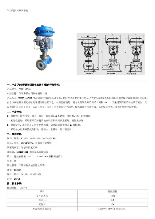
气动薄膜衬氟调节阀一、产品[气动薄膜衬四氟单座调节阀]的详细资料: 产品型号:ZJHP-16F46 产品名称:气动薄膜衬四氟单座调节阀 产品特点: ZMJBP-16F46P 气动薄膜衬四氟单座调节阀, 是自控仪表中的执行单元。
它由气动薄膜执行机构和直通单座衬氟塑阀两部份组成。
由于该阀接触介质的部位均采用高压注塑工艺,衬有能耐腐蚀、耐老化的聚全氟乙丙烯(简称 F46),又采用聚四氟乙烯波纹管密封,因 而该阀广泛适用于化工、石油、冶金、医药、电力等行业中对酸、碱强腐蚀介质和有毒、易挥发等气体、液体介质的过程控制。
二、产品特点: 1.耐腐蚀:阀体内腔、阀芯、阀座、阀杆均 316 不锈钢,能耐酸、碱,耐强腐蚀。
2.密封性能好:采用聚四乙烯材质的波纹管和填料双重密封,确保无渗漏。
3.泄漏量小:由于阀芯、阀座是软密封,故泄漏量低于国家 IV 级标准。
4.采用轻小型多弹簧执行机构,体积小,重量轻,调节精度高。
三、零件材料: 阀体、阀盖:HT200,ZG230-450,ZG1Cr18Ni9Ti 阀芯、阀座:1Cr18Ni9Ti,司太莱合金堆焊 软密封阀芯:增强聚四氟乙烯 波纹管:1Cr18Ni9Ti 聚四氟乙烯波纹管 填片:橡胶石棉板、10''、 1Cr18Ni9Ti 石棉缠绕垫片 膜盖:A3 波纹膜片:丁晴橡胶夹增强涤纶织物 弹簧:30SIMN 阀杆、推杆:2Cr13、1Cr18Ni9Ti 衬套:2Cr13 四、技术参数: 性能指标:(表一) 项目 基本误差% 回差% 死区% 额定流量系数误差 性能指标 ≤±8 ≤8 ≤6 ≤±10%(Kv≤5 时±15%)泄漏量 五、技术参数:(表二) 公称通径 DN(mm) 阀座直径 DN(mm) 3 4 G3/4'' 5 6 7 8 10 1.2 12 2 20 15 3.2 20 5 25 26 8 32 32 12≤0.01%阀额定容量40 40 2050 50 3265 80 100 65 80 100 50 70 100150 150 240额定流量系数 KV 0.08 1.12 0.20 .032 0.50 0.80 流量特性 公称压力 PN(Mpa) 配 用 执 行 机 弹簧范围 KPa 构 作用方式 工作温度 固有可调比 R 六、调节阀的允许压差:(见表三) 型号 有效面积 cm 工作行程 mm 200 10 直线直线\等百分比 1.01.6 ZHA-22 280 10 16 20-10040-200 气关式或气开式 -30~200℃ 30:1 ZHA-23 400 25 ZHA-34 630 40 ZHA-45 1000 60标准组配的气动单座阀,其气动薄膜执行机构的输出力是一定的。
隔膜阀>>衬氟隔膜阀>>衬氟隔膜阀产品详细信息隔膜阀系列价格供用户或设计院工程项目做预算一、阀门的选型步骤1.明确阀门在设备或装置中的用途,确定阀门的工作条件:适用介质、工作压力、工作温度等等。
2.确定与阀门连接管道的公称通径和连接方式:法兰、螺纹、焊接等。
3.确定操作阀门的方式:手动、电动、电磁、气动或液动、电气联动或电液联动等。
4.根据管线输送的介质、工作压力、工作温度确定所选阀门的壳体和内件的材料:灰铸铁、可锻铸铁、球墨铸铁、碳素钢、合金钢、不锈耐酸钢、铜合金等。
5.确定阀门的型式:闸阀、截止阀、球阀、蝶阀、节流阀、安全阀、减压阀、蒸汽疏水阀、等。
6.确定阀门的参数:对于自动阀门,根据不同需要先确定允许流阻、排放能力、背压等,再确定管道的公称通径和阀座孔的直径。
7.确定所选用阀门的几何参数:结构长度、法兰连接形式及尺寸、开启和关闭后阀门高度方向的尺寸、连接的螺栓孔尺寸和数量、整个阀门外型尺寸等。
8.利用现有的资料:阀门产品目录、阀门产品样本等选型适当的阀门产品。
二、阀门的选型依据1.所选用阀门的用途、使用工况条件和操纵控制方式。
2.工作介质的性质:工作压力、工作温度、腐蚀性能,是否含有固体颗粒,介质是否有毒,是否是易燃、易爆介质,介质的黏度等等。
3.对阀门流体特性的要求:流阻、排放能力、流量特性、密封等级等等。
4.安装尺寸和外形尺寸要求:公称通径、与管道的连接方式和连接尺寸、外形尺寸或重量限制等。
⑤对阀门产品的可靠性、使用寿命和电动装置的防爆性能等的附加要求。
(在选定参数时应注意:如果阀门要用于控制目的,必须确定如下额外参数:操作方法、最大和最小流量要求、正常流动的压力降、关闭时的压力降、阀门的最大和最小进口压力。
)根据上述选型阀门的依据和步骤,合理、正确地选型阀门时还必须对各种类型阀门的内部结构进行详细了解,以便能对优先选用的阀门做出正确的抉择。
管道的最终控制是阀门。
隔膜阀a-es71t1230dn125说明书
手动隔膜阀的操作很近似于胶管阀的操作。
旋转手轮是压缩器下降,开始像阀体底壁推动隔膜。
在节流状态,手动操纵器旋转到所需的流量处之后并停留在该处。
在开-关状态,达到大压力时,两个表面则达到严密的密封。
当隔膜阀打开时,手动操纵器的旋转作用则相反,
当闭合元件提升后扩大了流动面积。
终,在全开位置,压缩器完全收缩到阀盖帽内部,隔膜远离物流。
在此点阀门达到它的全面积容量。
总之隔膜阀提供固有等百分比流动特性,该特性在操作时往往会直线运动。
1、隔膜阀开关不能用F扳手,而且开到底时,再关一圈,不能开到底。
2、丝杠要定期加黄油。
3、阀门关闭时不能用太大的力,以防膜片损坏。
4、螺栓要定期加黄油,以防生锈。
5、阀门损坏后,要拆开检查,如果只是膜片损坏,只更换膜片就可以了。
更换膜片时,阀门要处于全开状态。
安装与维护
隔膜阀安装前应仔细核对管路的运行条件是否与本阀规定的使
用范围相符,并应清洗内腔,以防止污物卡阻或损伤密封部件。
橡胶衬里层和橡胶隔膜表面切勿涂刷油脂类物品,以防橡胶溶胀,影响隔膜阀使用寿命。
手轮或传动机构,不允许作起吊用,并严禁碰撞。
手动操作隔膜阀时,不得借助于辅助杠杆,以防扭力过大而损伤驱动部件或密封部位。
隔膜阀应存放在干燥通风的室内,严禁堆放,库存隔膜阀的两端通道必须封口,且启闭件应处于微开启状态。
隔膜阀使用方法及技巧隔膜阀使用方法及技巧:轻松驾驭的小窍门嘿,朋友们!今天咱来唠唠隔膜阀这个小家伙。
这玩意儿可不简单,要是你能用得好,那可是能让你的工作事半功倍!首先呢,咱得搞清楚隔膜阀是干啥用的。
它就像是个“流量小管家”,能控制流体的通断。
别小看它,作用大着呢!那怎么使用它呢?嘿,这里面可有讲究。
就跟咱骑自行车似的,得先掌握好平衡。
安装隔膜阀的时候可得仔细咯,螺丝要拧紧,不能有松动,不然可就容易“泄气”啦!接下来就是操作啦。
打开关闭隔膜阀的时候,动作别太猛,温柔点儿,不然它可要“发脾气”的,说不定就给你整点小故障。
就像追女朋友一样,得小心翼翼,慢慢来。
嘿,说到这我想起个事儿。
有一次我那同事啊,对隔膜阀那是“粗暴对待”,结果可好,阀门马上就“闹别扭”,漏了一地的液体,把大家都给忙坏了。
所以啊,对隔膜阀可得有耐心,别把它惹毛了。
还有就是要注意隔膜阀的保养。
这玩意儿跟咱人似的,也得时不时地保养保养。
定期检查一下,看看隔膜有没有损坏,要是有问题及时更换。
别舍不得那点小钱,不保养的话以后出大问题可就得不偿失啦。
再有就是,不同的隔膜阀适用的场合也不一样。
就像你不能穿着拖鞋去参加正式场合一样,得根据实际情况选择合适的隔膜阀。
其实啊,掌握隔膜阀的使用方法和技巧并不难,只要你用心去感受它,和它“友好相处”,它肯定也会乖乖听你话的。
总之呢,隔膜阀这个小家伙虽然不太起眼,但是用处可大着呢。
咱得善待它,掌握好使用方法和技巧,让它为咱的工作服务。
咋样,听我这么一说,是不是觉得隔膜阀也没那么难搞定了呀?哈哈,那就赶紧去试试吧!。
隔膜阀膜片安全操作及保养规程隔膜阀是一种常用的工业管道阀门,在各种工业生产和管道输送的系统中都发挥着重要作用。
隔膜阀的核心部分是膜片,膜片负责隔离介质,防止流体泄漏。
为了保障设备运转安全和延长使用寿命,必须掌握隔膜阀膜片的安全操作及保养规程。
1. 隔膜阀膜片安全操作规程1.1 安装前的准备工作在安装隔膜阀之前,必须进行以下准备工作:•核对隔膜阀的型号、规格和标准,确保符合要求;•清洁隔膜阀的封堵面和连接口,保证无异物,无损伤;•根据实际需要选择合适的安装方向,避免箭头反向,导致介质流动方向相反;•安装隔膜阀前,应仔细检查各连接点,确保安装牢固、紧密。
1.2 操作规程在隔膜阀的操作过程中,需要注意以下规程:•对于新安装的设备,建议在首次使用前进行漏检试验;再进行使用。
漏检试验应当在介质压力基础上增加50%~150%进行试验;•充分了解隔膜阀的工作原理,按照要求进行操作,不得随意改变介质流动方向;•开启或关闭隔膜阀时,应逐级操作,避免突然回关,对阀门和膜片造成不必要的损伤;•在操作隔膜阀时,工作人员应注意保护膜片,切勿使用尖锐物体或手动撕扯膜片。
1.3 技巧操作隔膜阀在正常运作时,如对膜片进行以下技巧操作,会增加其使用寿命:•避免过度压力,不得超出额定压力范围,以免膜片损伤;•不要过度曲折、拉伸、张力过大等,以免膜片老化;•保证阀门工作温度不超出膜片耐高温极限,以免膜片老化、粘结或变形。
2. 隔膜阀膜片保养规程2.1 日常保养日常保养应当每周1-2次。
具体保养规程包括:•检查隔膜阀阀体有无变形、泄漏和启闭是否灵活;•检查膜片表面是否有撕裂、老化、硬化及粘结等现象;•检查阀门附件的操作机构、气缸、电动机、限位开关的工作是否正常;•移动操作机构,将隔膜阀阀叶开启、关闭几次;•清除隔膜阀内外表面的污垢、灰尘。
2.2 季节性保养每隔一定时间(如6个月到12个月),对隔膜阀做彻底的季节性保养:•拆卸隔膜阀,拆除膜片并进行清洗和检查;•检查隔膜阀的阀体、导向板、气缸、电机、机构等元件;•如果膜片老化或损坏,更换膜片;•给阀体、导向板、膜片以涂防腐漆。
衬氟微阻缓闭止回阀安全操作及保养规程1. 前言衬氟微阻缓闭止回阀是一种流量控制阀门,广泛应用于工业生产中。
为了确保运行安全和阀门寿命,必须按照规定的操作方法和维护程序进行操作和保养。
2. 安全操作规程2.1 操作前的准备2.1.1 了解工艺流程和控制方案,确保了解阀门的开关方式和特性。
2.1.2 检查管道和阀门的连接情况,确保密封良好,管道没有堵塞或磨损现象,并检查管道和阀门是否清洁。
2.1.3 检查阀门是否处于关闭状态,并将阀门插销或锁定保持在关闭位置。
2.2 操作过程2.2.1 在操作前,请先阅读相关说明和安全规程。
2.2.2 操作时应逐步开启或关闭阀门,避免过快的转动,以免产生过大冲击力或损坏阀门。
2.2.3 在开始操作之前,应等待系统进入静止状态,确保无压力状态下进行。
2.2.4 在操作过程中,必须检查管道内压力,确保操作压力不超过设定值。
2.2.5 在操作过程中,如果发现不正常的声音或漏气现象,请立即停止操作。
2.2.6 操作完成后,请关掉阀门并将阀门插销或锁定插头安装好。
3. 维护和保养3.1 维护前的准备3.1.1 在进行维护前,请确保阀门已经关闭,并且拆下金属密封圈并清洁。
3.1.2 在进行维护时,请使用相应的工具和设备,避免使用钳子等粗糙工具损坏阀门。
3.1.3 在进行维护时,请注意安全,戴上手套和防护眼镜。
3.2 维护过程3.2.1 清洁阀门周围的管道和阀门身,检查并保持阀门平稳。
3.2.2 检查阀门阀芯,保证其光滑并清洁。
3.2.3 检查密封面是否平整,金属密封圈是否适合。
3.2.4 检查阀门内部零部件的状况,确保没有损坏或腐蚀,同时请注意定期更换阀芯或密封圈。
3.2.5 在擦拭密封面之前,请用温水或无机溶液清除表面附着物。
3.2.6 维护完成后,请再次检查密封面是否均匀平整,并将阀门重新安装到管道上。
3.3 保养3.3.1 定期检查管道和阀门的运行情况并进行清洁维护。
3.3.2 定期更换阀芯和密封圈,避免出现问题和故障。