BEKOMAT16CO中文说明书
- 格式:pdf
- 大小:739.66 KB
- 文档页数:13

PoExtBusOC16-CNC User’s manualPlease read the following notes1.All information included in this document is current as of the date this document is issued. Such information,however, is subject to change without any prior notice.2.PoLabs does not assume any liability for infringement of patents, copyrights, or other intellectual property rightsof third parties by or arising from the use of PoLabs products or technical information described in this document.No license, express, implied or otherwise, is granted hereby under any patents, copyrights or other intellectual property rights of PoLabs or others. PoLabs claims the copyright of, and retains the rights to, all material (software, documents, etc.) contained in this release. You may copy and distribute the entire release in its original state, but must not copy individual items within the release other than for backup purposes.3.Descriptions of circuits, software and other related information in this document are provided only to illustratethe operation of the products and application examples. You are fully responsible for the incorporation of these circuits, software, and information in the design of your equipment. PoLabs assumes no responsibility for any losses incurred by you or third parties arising from the use of these circuits, software, or information.4.PoLabs has used reasonable care in preparing the information included in this document, but PoLabs does notwarrant that such information is error free. PoLabs assumes no liability whatsoever for any damages incurred by you resulting from errors in or omissions from the information included herein.5.PoLabs devices may be used in equipment that does not impose a threat to human life in case of themalfunctioning, such as: computer interfaces, office equipment, communications equipment, test and measurement equipment, audio and visual equipment, home electronic appliances, machine tools, personal electronic equipment, and industrial robots.6.Measures such as fail-safe function and redundant design should be taken to ensure reliability and safety whenPoLabs devices are used for or in connection with equipment that requires higher reliability, for example: traffic control systems, anti-disaster systems, anticrime systems, safety equipment, medical equipment not specifically designed for life support, and other similar applications.7.PoLabs devices shall not be used for or in connection with equipment that requires an extremely high level ofreliability and safety, as for example: aircraft systems, aerospace equipment, nuclear reactor control systems, medical equipment or systems for life support (e.g. artificial life support devices or systems), and any other applications or purposes that pose a direct threat to human life.8.You should use the PoLabs products described in this document within the range specified by PoLabs, especiallywith respect to the maximum rating, operating supply voltage range and other product characteristics. PoLabs shall have no liability for malfunctions or damages arising out of the use of PoLabs products beyond such specified ranges.9.Although PoLabs endeavors to improve the quality and reliability of its products, semiconductor products havespecific characteristics such as the occurrence of failure at a certain rate and malfunctions under certain use conditions. Further, PoLabs products are not subject to radiation resistance design. Please be sure to implement safety measures to guard them against the possibility of physical injury, and injury or damage caused by fire in the event of the failure of a PoLabs product, such as safety design for hardware and software including but not limited to redundancy, fire control and malfunction prevention, appropriate treatment for aging degradation or any other appropriate measures.age: the software in this release is for use only with PoLabs products or with data collected using PoLabsproducts.11.Fitness for purpose: no two applications are the same, so PoLabs cannot guarantee that its equipment orsoftware is suitable for a given application. It is therefore the user's responsibility to ensure that the product is suitable for the user's application.12.Viruses: this software was continuously monitored for viruses during production; however the user is responsiblefor virus checking the software once it is installed.13.Upgrades: we provide upgrades, free of charge, from our web site at . We reserve the right tocharge for updates or replacements sent out on physical media.14.Please contact a PoLabs support for details as to environmental matters such as the environmental compatibilityof each PoLabs product. Please use PoLabs products in compliance with all applicable laws and regulations that regulate the inclusion or use of controlled substances, including without limitation, the EU RoHS Directive. PoLabs assumes no liability for damages or losses occurring as a result of your noncompliance with applicable laws and regulations.15.********************************************************************************************contained in this document or PoLabs products, or if you have any other inquiries.16.The licensee agrees to allow access to this software only to persons who have been informed of and agree toabide by these conditions.17.Trademarks: Windows is a registered trademark of Microsoft Corporation. PoKeys, PoKeys55, PoKeys56U,PoKeys56E, PoKeys57E, PoExtension, PoScope, PoLabs and others are internationally registered trademarks.PoExtBusOC16-CNC user’s manual1. Description (4)2. Features (4)Installation (5)PCB dimensions and mounting holes (9)3. Grant of license (10)PoExtBusOC16-CNC is an extension board for driving up to 8 stepper motor signals. It contains 8 standard 10-pin connectors for directly connecting the stepper or servo motor drivers. Each connector provides step, direction and shared enable signals.Similar device PoExtBusOC16 (without CNC) is designed for providing up to 16 digital outputs and is not compatible as it uses a different wiring scheme. Unlike with PoExtBus devices, only one PoExtBusOC16-CNC can be used and daisy-chaining is not supported.2.Features-Up to 8 stepper motor drivers can be connected-Enable signal for each driver-PoExtension connector for connecting to master device-Only one PoExtBusOC16-CNC can be usedFigure 4: PoExtBusOC16-CNCPoExtBusOC16-CNC uses 6 pins from the PoExtension connector. Use the wiring scheme as shown in Table 1 in case the PoExtension connector is not available on the master device. PoExtBusOC16-CNC is shipped with the cable attached to the PoExtensionIn.To use PoExtBusOC16-CNC with PoKeys57E/PoKeys57U connect the flat cable to the appropriate pins of PoKeys57E/57U device.Other pins are not used.Postep25-32 has the same pin out as the PoExtBusOC16-CNC motor outputs so you can simply connect them with the 10-pin flat cable.Please note that PoExtBusOC16-CNC does not support error inputs for status feedback. Pin 7 is connected to GND.Figure 5: Postep25-32 connected to PoExtBusOC16-CNC4.Configuration with PoKeys deviceThe PoExtBusOC16-CNC functions as an external pulse generator without I/O capability. The following sections provide instructions on how to configure it for operation with Mach3, Mach4 plugins and in standalone operation with the PoKeys device.Motor enable signal is assumed to be connected to pin 1 of the PoKeys device. This can be changed to a different pin if required.PoKeys Mach4 pluginFirst, the PoKeys device needs to be configured for operation with the Mach4 plugin. If this hasn’t been done already, follow the Mach4 plugin instructions when adding the PoKeys57U or PoKeys57E device to plugin configuration. In the new device wizard, set the Pulse engine options to ‘External 8ch without IO’.Set the following Pulse engine settings in the device configuration dialog in the plugin:-Pulse engine configuration: External 8ch without IO-Enable out for motor 1: select ‘Pin 1’PoKeys Mach3 pluginFirst, the PoKeys device needs to be configured for operation with Mach3 plugin. If this hasn’t been done already, follow the Mach3 plugin instructions when adding the PoKeys57U or PoKeys57E device to plugin configuration.Once the PoKeys device is configured, set the following settings:-Pulse engine settings:o Pulse engine configuration: External 6ch without IO-PoKeys mapping settings:o Set function of pin 1 (motor enable signal) to ‘Output’o Select ‘Output Enable1’ from the options in the IO columno Clear‘Invert’ check boxStandalone operationUse PoKeys software to configure the device for a standalone operation.First, configure pin 1 (motor enable output) as ‘Digital output’. Click ‘Send to device’.Then, open Pulse engine settings follow these steps:-Release the settings lock by clicking ‘Lock settings’. The dialog will be asking you whether you want to load default settings. Confirm with ‘Yes’-Select ‘External’ in Pulse engine generator options and uncheck the ‘Extended IO’ check box -Select 8 channels in Pulse engine generator options-Select pin 1 in ‘Axis enable output on pin’-Click ‘Save configuration’To test the operation of the device, switch Pulse engine into ‘Running’ mode (by clicking ‘Running’square’) and use the +/- jogging buttons for the target axis. The default jog speed is 1 % of the maximum speed - use the slider at the bottom to adjust the jogging speed.PCB dimensions and mounting holes5.Grant of licenseThe material contained in this release is licensed, not sold. PoLabs grants a license to the person who is using any compatible PoLabs product, subject to the conditions listed below.1.AccessThe licensee agrees to allow access to this manual only to persons who have been informed of and agree to abide by these conditions.ageThe information in this release is for use only with PoLabs products.3.CopyrightPoLabs claims the copyright of, and retains the rights to, all material (software, documents etc) contained in this release. You may copy and distribute the entire release in its original state, but must not copy individual items within the release other than for backup purposes.4.LiabilityPoLabs and its agents shall not be liable for any loss or damage, howsoever caused, related to the use of PoLabs equipment or software, unless excluded by statute.5.Fitness for purposeNo two applications are the same, so PoLabs cannot guarantee that its equipment or software is suitable for a given application. It is therefore the user's responsibility to ensure that the product is suitable for the user's application.6.Mission Critical applicationsBecause the software runs on a computer that may be running other software products, and may be subject to interference from these other products, this license specifically excludes usage in 'mission critical' applications, for example life support systems.7.ErrorsThis manual was continuously monitored for errors during production; however the user is responsible for error checking the manual once it is used.8.SupportThere could be errors in these manual, but if you found some, please contact our technical support staff, who will try to fix the problem within a reasonable time.9.UpgradesWe provide upgrades, free of charge, from our web site at . We reserve the right to charge for updates or replacements sent out on physical media.10.TrademarksWindows is a registered trademark of Microsoft Corporation. PoKeys, PoKeys55, PoKeys56U, PoKeys56E, PoKeys57E, PoExtension, PoScope, PoLabs and others are internationally registered trademarks.Support: 。

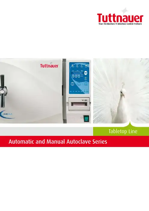
Tabletop LineWe have consistently provided solutions to various markets and offer a wide range of innovative cleaning, disinfection and sterilization products, varying in size and application including: • An extensive variety of tabletop autoclaves for dental clinics and small to medium clinics, or as a second unit in medical centers and hospitals • Cleaning, disinfection and sterilization products for CSSD use • Industrial size sterilizers for hospitals and research institutes • Laboratory autoclaves ranging in size and application • Washers and disinfectors for dental clinics, hospitals and laboratories Our autoclaves incorporate proven design and engineering features, resulting in a durable, warranted solution that meets international standards including FDA, ASME, ISO and CE Medical Devices.Global partnershipsAt Tuttnauer we feel that business means people dealing with people. We pride ourselves on our reputation for having long-lasting relationships with our customers, spanning over decadesand distances and for building solid, long-term relationships based on commitment and trust. Our Flexibility is Your Advantage Beyond our unmatched range of products, we also manage complete turnkey solutions, including planning, design and installation of equipment, as well as consultation and feasibility studies, for projects of all sizes. Backed by deep industry experience and a track record of success, Tuttnauer continues to help medical and research institutes all over the world to plan and execute their sterilization and infection control policies.One Area of Expertise, Many Areas of ApplicationTuttnauerYour Sterilization & Infection Control PartnerCompany ProfileFor over 80 years, Tuttnauer’s sterilization and infection control products have been trusted by hospitals, universities,research institutes, clinics and laboratories throughout the world. Supplying a range of top-quality products to over 100countries, Tuttnauer has earned global recognition as a leader in sterilization and infection control.Tuttnauer invests its full energies and resources in one area of expertise – sterilization and infection control. From our start, in 1925, we have worked on large-scale joint projects with leading research institutes and universities. This cooperation allows us to remain at the forefront of our field, developing and integrating the most advanced methods and technologies.We share your commitment to help protect your staff and patients against the spreadof infectious diseases and to maintain a risk-free environment. The demand forstricter sterilization guidelines is on the rise, especially since the advent of AIDS andthe development of virus mutations, which makes the battle for a cleaner and saferenvironment ever more challenging.What is sterilization?Sterilization is a vital component of Infection Control procedures, the term used to describethe entire range of activities intended to achieve a clean, disease-free environment.Sterilization is defined as the destruction of all transmissible agents, bacteria and virusesfrom surfaces, medical instruments, food or any product that needs to be safely usedwithout endangering the user.Increased regulations and the requirement for proper sterilization in private clinics, tattooparlors and beauty salons have given rise to the demand for sterilizers that are easy touse and maintain.We believe that proper education, advanced technologyand ease of use contribute to improved sterilization results.Tuttnauer Automatic Autoclave SeriesToday, dental and medical clinics are voicing the demand for better sterilization. Tuttnauer is your partner in protecting your patients and gaining their trust. Our state of the art sterilization technologies are designed to deliver quality without compromise.Tuttnauer Automatic Autoclaves produce the highest return on your investment by offering:• Rapid cycles• Low maintenance•Durability• SafetyBenefits:• Rapid cycles optimize the availability of ready-to-use sterile instruments• Easy-to-use, single touch control system increases productivity • Enhanced monitoring for consistent documentation of sterilization results• Long lasting, easy to maintain autoclaves Automatic Series Features:• pre-set sterilization programs• Program and customize cycle parameters to meet your needs • High precision control system for accurate sterilization results • Integrated printer for cycle documentation (optional)• PC Communication port enables storage of sterilization results • Temperature and pressure monitoring• User friendly, intuitive display• Cycle information recovery in the case of power failure or cycle interruption• Insufficient water detector with automatic shutoff •Consistent monitoring of temperature and pressure for real-time accurate results• Water-level sensors prevent cycle activation when insufficient water is detected in the chamber or reservoirCapacity:Our high-capacity models are available in 65 and 85 Liter chamber sizes. These models are designed for clinics that have a higher volume of instrument turnaround, therefore decreasing the clinic’soperational costs. Providing a safe environment is our priority5Control PanelInteractive Control System: Monitoring is essential for correct infection control in your private practice.Tuttnauer Automatic Autoclaves feature a user friendly, micro -processor control system which offers enhanced monitoring, providing the control and flexibility you need. In addition password protection provides for secure access. The LCD displayis easy to read with sharper and brighter indicator lightsSterilization Programs:The autoclave offers preset sterilization programs, at temperatures of up to 1 °C ( 7 °F) and 1 dry only program. Cycle parameters can be customized to suit your needs.Double locking safety deviceSafety and Convenience features:• Seamlessly integrated into your work environment with compact design and heat insulation• Durable 16L type stainless steel chamber and door with electro-polish finish• Double locking safety device prevents door from opening while chamber is pressurized• Control lock-out switch prevents starting a cycle if door is not properly locked• Door failure protection prevents door from opening at high pressure16L type stainless steelwith electro-polish finishProgram Selector Detailed Digital Display Programmable KeysCycle Status Indicators00626How to Select the Right Model for your Needs?Tuttnauer Automatic Autoclave Series is available in a wide range of models: E, EK, EA and EKA. E / EKThese models are available in two modes: The quick cycle model, EK, decreases heating time by over 50%, resultingin fast and efficient sterilization cycles and quick instrument turnaround. The EK is the perfect choice for the active clinic. The standard E model provides all the dependable features of the automatic autoclave line.7Closed Door Active Drying Air Pump:With extra fast and efficient drying cycles, the EKA and EA autoclaves significantly increase your productivity. These two models have the added benefit of a high efficiency air pump which allows closed door active drying. The EKA and EA are built for improved sterilization with the ability to dry packs and pouches.Benefits:• More thorough drying and sterilization • Faster drying for a shorter overall cycle• 0. µm HEPA air filter provides sterile, bacteria-free air for drying34 Liter Chamber Models64/85 Liter Chamber Models7.5 Liter Chamber Models19/23 Liter Chamber Models-Tested for unwrapped instruments. Cycle times includes heatup, sterlization exposure and exhuast. All cycle times may vary with instrument load and voltage.- All printers are optionalEA / EKA - Fully Automatic Autocalves8Tuttnauer Manual Autoclave SeriesSimplicity at Work M/MKThe Manual Autoclave is an affordable sterilizer for private clinics that do not want to compromise on quality, safety and reliability. Tuttnauer manual autoclaves are an effortless Plug n' Play solution. After installation, the sterilizer is virtually maintenance free with reduced running costs.Benefits:• Tuttnauer Manual Autoclaves last longer• Durable components significantly reduce maintenance expenses • Ease of use eliminates the need for specialized staff to operate sterilizerSafety and Convenience features:• Heat insulation and quiet operation for pleasant office environment• Durable 16L type stainless steel chamber and door with electro-polish finish• Double locking safety device prevents door from opening while chamber is pressurized• Pressure activated lock prevents door from opening if chamber is pressurized• Door failure protection prevents door from opening at high pressure• Automatic safety shutoff prevents overheating • Insufficient water detector with automatic shutoff11Pressure Gauge 2Timer 3Thermostat 4Function Selector64/85 Liter Chamber Models34 Liter Chamber Models7.5 Liter Chamber Models19/23 Liter Chamber Models0062-Tested for unwrapped instruments. Cycle times includes heatup, sterlization exposure and exhuast. All cycle times may vary with instrument load and voltage.910Tuttnauer reserves the right to change parts and accessories as necessary without prior notice.Model2540MKA Chamber Dimensions øxL (mm) 5 x 76Chamber Volume Liter Cold Cycle Time 16 min.Hot Cycle Time1 min.2540MKA - The First Manual Autoclave with Closed Door DryingThe 5 0MKA, features heating auto-shutoff at completion of sterilization cycle, saving energy and increasing your safety and productivity. Before leaving the clinic, set the 5 0MKA to night mode, start a cycle and the instruments will be sterile and ready to use on return.• Closed door active drying air pump • Single Action Sterilization Cycle • Overheat Safety protection• Automatic night mode shutoff, a time and energy saver1Cycle Status Indicator 2Pressure Gauge 3Power Switch 4Sterilization Timer 5Water Pump Switch 6Drying and Sterilization Timer 7Temperature Selector 8Night Mode Switch16587 AccessoriesImpulse Sealing MachinesSterilization is effective only if the sterility of the instruments is preserved from the point of sterilization until they are used. The sealing process ensures that the instruments remain sealed after sterilization and maintain perfect sterility during their shelf-life. Our range of fast and reliable impulse sealers complies with the strictest quality and safety standards (DIN 5895 -7). For rapid instrument turnaround we offer an automated range of rotary sealing machines.Water DistillerUse mineral-free water to protect your autoclave and instruments. Chamber Brite™Chamber Brite™ effectively cleans and descales the chamber, the reservoir and copper tubing of any steam autoclave.- Cycle time may vary with instrument load and voltage• Increases the life of the autoclave piping system• Distilled water at the fraction of the cost of bottled distilled waterFeaturing Tuttnauer’s range of cleaning, disinfection and sterilization solutionsLarge sterilizers for various industries and market needs Laboratory autoclaves rangingin size and applicationWashers/disinfectors for hospitals and laboratoriesMore from Tuttnauer:Pre & post vacuum tabletop sterilizers designed to performclass B cycles。

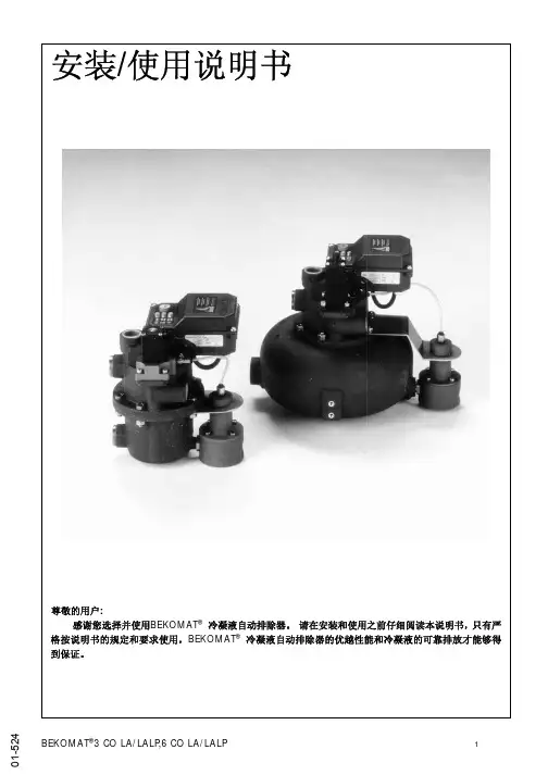
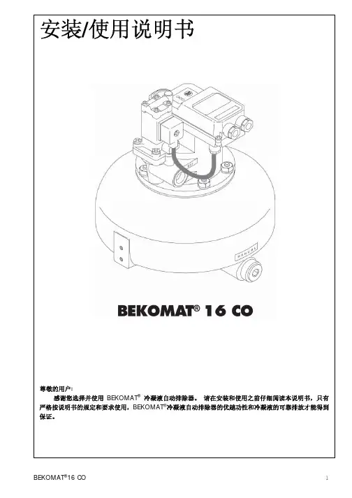
Condensate technology | BEKOMAT ® 31U | 32U | 33U | 33U CODuring compressed air generation and processing, the optimum quality for the application should be achieved. It is important to remove contaminants and humidity from the compressed air as these can lead to quality problems, failures or loss of production. Condensate discharge without compressed air lossThe BEKOMAT® drains off condensate withoutloss of compressed air, thus reducing energy costs and CO2emissions. This is made possible by the integrated capacitive sensor,smart electronics for volume-controlled condensate dischargeand the proven pilot-controlled solenoid valve.The BEKOMAT® designed for quick and cost-effective servicing The innovative design of the BEKOMAT® 31U, 32U, 33U and 33U CO models is optimised for easy handling, installation and maintenance. The devices consist of no more than three assemblies joined together with quick-release connectors. Once installed, the control and sensorunit stays in place as only theservice unit (including all wearand pressure parts) needs to beexchanged.This sturdy condensate drain issuitable for both oil-contaminatedand oil-free, aggressivecondensate. ›No loss of compressed air during draining ›Low operating costs›Outstanding reliability›Durable and resistant to dirt›Large valve diameters prevent the formationof emulsions›No delicate mechanical components›Suitable for temperatures up to +70 °C› Easy to install and virtuallymaintenance-free›Versatile connection options›Easy exchange of service unit, even wherespace is confirmed with even in small areas›Servicing requires no installation work›Automated operationand monitoring›Ready for integration into modern systemmonitoring installations›Automatic start of self-cleaning processbased on dirt particle load›Service indicator warns operators in advancewhen the service unit needs to be replacedThe quickest route to efficiency: the BEKOMAT ® with service unitDimensions in mmDepth: 65Dimensions in mm* For more information on climate zones ( | | ) see reverse** Short-term peak volume can only be achieved if the device is correctly installed according to the operating manual. If in doubt, a install venting line.Depth: 73BEKO TECHNOLOGIES Ltd Unit 11-12 Moons Park Burnt Meadow Road North Moons Moat Redditch, B98 9PAPhone + 44 (0) 1527 575778 *************************.uk carbon neutral | DE-077-457728print production78-00073e.g. Northern Europe, Canada, Northern USA, Central Asia e.g. Central and Southern Europe, Central Americae.g. South-East Asian coastal regions, Oceania, Amazon and Congo regionsTemperature range: 1 to + 60 °CClimate – a key factorThe general climate and the ambient temperature are important factors for the formation of condensate in compressed air systems. That is why we quote separate performance data of our BEKOMAT ® models for three climate zones:Like all high-performance devices, the BEKOMAT ® needs to be serviced from time to time. This is done with our service unit containing all the necessary wearing parts. If you require assistance, contact our service technicians, who are also qualified to examine and assess your entire compressed air system for further optimisation.Service unitSubject to technical changes without prior notice. Errors and omissions excepted.Visit us atDo you have questions about the best way of processing your compressed air?We have the answers! We offer efficient solutions for any type of processing chain. Please contact us with all your queries. We would be delighted to tell you more about our condensate treatment, filtration, drying, measuring and process technology, and our comprehensive services.。

T anker & Overfill• C U S T O M E R S E R V I C E • I N N O V A T I O N • M A N U F A C T U R I N G • Q U A L I T Y • T E C H N I C A L E X P E R T I S E • E X C E L L E N C E • D E S I G N •Customer Service: Email: ********************.uk2T elephone: +44 (0)1772 323529 Email: ********************.ukTanker ProductsAPI ValvesDry Disconnect Adapters API Loading Arm CouplerDry Disconnect CouplersA Bayco dry disconnect adapter helps prevent spillage from normal or accidental disconnects.Features:• 2 piece adapter for easy rebuilding• Interchangeable with Kamvalok ™ style fittings • A luminium fittings have aluminium nose piece and brass piston Size: 2” - 4”Thread: Various connections available Material: Aluminium or stainless steel Seal:Various materialsMust be used with Bayco style coupler for adapter to ed for bottom loading/unloading of petroleum tankers.Available Options:• Ergonomic handle to allow manual operation • Load only and load/unload valves • Sight glass & flow indicator • Fixed/Removable handle • Various seal options availableSeals can be replaced without the need to remove from the tanker.Plastic and metal dust caps are available for the API valves.The 5300 coupler is completely modular so it can be built with various face seal combinations to be compatible with alternative fuel / performance levels and applications. Two models are available: bonded nose seal and replaceable nose seal.Features:• 4” TTMA inlet mounting flange• 5 cam design for easy alignment/tight connection • Ball-end handle for easy, comfortable operation • S haft seals can be changed without removing coupler from the loading arm• Compliant with API RP1004:2003 specificationsSize: 1½” - 4”Thread: Various connections available Material: Aluminium or stainless steel Seal:Various materialsMust be used with Bayco style adapter for coupler to operate.• H eavy duty stainless steel crank and link • S tainless steel handle allows exposure to corrosive chemicals or washdown service • F ully interchangeable with Kamvalok ™ style fittings • Stainless steel internal • D ixon EZ Boss-Lock cam arms provide high security from accidental opening on 1½” and 2” fittings • L arge EZ Boss-Lock paddle type cam arms allow for easy grip on 3” fitt i ngs3T elephone: +44 (0)1772 323529 Email:********************.ukTanker ProductsGravity Drop AdapterSequential Vapour VentsVapour Return ValveBall Nozzles for Bulk DeliveryDixon manufacture two styles of gravity drop adapter.Standard one piece design • Quality cast aluminium • Various seal options available• Bronze cam arm with stainless steel pins and finger rings • Optional sight glassTwo piece bolt together design with sight glass • C onsists of a ring assembly and an outlet which contains mounting balls, sight glass and seals Both styles available 3” - 4”.• U sed for venting tank vapours during the bottom loading and unloading of petroleum tankers• O ptions for 16” or 20” tank manholes available• Heavy duty cast aluminium body• 4” adapter with or without poppet valve, round TTMA connection • Air interlock mountVapour caps available in Nylon and Aluminium complete with built in locking feature, centred T handle, colour coded orange for safety, hole for a chain/lanyard.• Uses a full port ball valve for high flow rate• T he internal flow path is designed to provide low pressuredrop across the nozzle. Lower pressure drop permits higher flow rates at lower pressure • Reduces foaming and backupsOur unique swivel design permits low temperature operation without leakage around the O-ring seals. The swivel freely rotates at temperatures as low as -40°C and pressures as high as 7 Bar / 100 PSI.Hardened chrome steel roller balls and hardened carbon steel ball race provide long service life.Composite Hose AssembliesDixon offers a range of anti static suction and discharge composite hose assemblies designed for use on plant or road/rail tankers.Hose construction is exceptionally flexible for ease ofhanding yet remains robust, hard wearing and cost effective.A comprehensive range of fittings and hose assembly service is available.4T elephone: +44 (0)1772 323529 Email: ********************.ukFloTech Overfill Prevention ProductsOverfill Prevention ProbesFT555 Truck TesterOverfill Prevention SocketsThe FloTech 2 & 5 wire optic overfill prevention probes are manufactured in accordance with EN13922.• T hey feature a unique prism sealing design that prevents product and vapour entering the electronics and causing probe failure• Probes are available in 7”, 12” & 18” lengths • F ully compatible with installed industry standard rack monitorsThe FloTech Plug & Play system provides a pre-made wiring harness that simply connects to each of the probes and sockets by way of suitable environmentally protected connectors. With this system, there is no need to strip wires and make crimp connections.Fully automatic truck tester capable of testing API optic systems and API Thermistor systems.• O ne man “wet test” feature of the FT555 will sound an audible alarm when probe is wetted• L CD screen displays the final test results and a pass/fail indication for easy rapid testing of the overfill system • A PI plug can be reconfigured for both Optic and Thermistor J Slot standardsSockets allow for the transfer of the electronic signal from the terminal control monitor to the tanker. Sockets will vary depending upon terminal equipment.• S ocket options include 6 pin, 3 J slot for 5 wire systems and 10 pin, 4 J slot for 2 wire systems• S ockets can include a brake interlock to prevent drive away, vapour recovery interlock or bothFloTech sockets use a patented detachable nose ring that permits replacement without the need to disconnect the wiring.Dixon offer a complete range of replacement parts for your overfill systems.Replacement Parts。

铁皮石斛仿野生环境智能监测虚拟仿真实验软件说明书北京欧倍尔软件技术开发有限公司2021 年7 月地址:北京海淀区清河永泰园甲1号建金商厦515-516室邮编:100085地址:北京海淀区清河永泰园甲1号建金商厦515-516室 邮编:100085 目录目录 (2)一、软件介绍 (3)二、功能介绍 (3)(一)软件场景 ............................................................................. 错误!未定义书签。
(二)变压器认知功能 ................................................................. 错误!未定义书签。
2.1基本知识认知 ........................................................................... 错误!未定义书签。
2.2工作原理认知 ........................................................................... 错误!未定义书签。
2.3变压器结构认知 ....................................................................... 错误!未定义书签。
2.4变压器拆装练习 ....................................................................... 错误!未定义书签。
(三)变压器实验功能 ......................................................................... 错误!未定义书签。
3.1实验场景界面 ........................................................................... 错误!未定义书签。

Digital mixing has revolutionizedso much of the live-entertainment production workflow. But one thing that hasn't changed is having to roll out that heavy, cumbersome old analog snake. That is until now! The new S16 Digital Snake from BEHRINGER takes the burden out of connecting your FOH (Front of House) console with the talent. The S16 provides 16 fully programmable, remotely controllable high-end mic preamps plus 8 analog, balanced XLR returns at the stage end, and connects to the FOH via a single CAT5 cable without the needfor a dedicated router. KLARK TEKNIK,a longtime industry-leader in the development of high-end digital audio processing, provided the SuperMAC technology that made all of this possible—BEHRINGER made it affordable.Massive ConnectivityWhen used as part of a completeX32 system, two S16 Stage Boxes canbe cascaded via the built-in AES50 ports, providing connectivity for up to32 mic/line inputs, 16 balanced outputs and the incredibly-affordable POWERPLAY P-16 Personal Monitoring System,which can feed up to 48 individual monitor mixers. We also included two optical ADAT sockets for connecting channels 1-8 and 9-16 to outboard devices, a convenient USB port for system updates via your PC, plus MIDII/O for lighting systems and sound module control.I/O Box with 16 Remote-Controllable Mic/Line Inputs, 8 Outputs and AES50 Networking featuring KLARK TEKNIK SuperMac Technology16 fully programmable and remote-controllable audiophile mic preamps8 analog, servo-balancedXLR outputsAES50 network ports featuringKLARK TEKNIK SuperMactechnology for ultra-low latency(in-ear compatible)Up to 100 m networking capabilityvia CAT-5e cable (not included)Dual AES50 ports for cascading S16units—no merger or router requiredPrecise LED metering plus 7-segment displays for signal control on stagePhones output assignable toany of the inputs/outputs foron-stage monitoringConnectivity for BEHRINGER's P-16Personal Monitoring System forIn-Ear applications (not included)Dual ADAT outputs for use in splitter mode and stand-alone digital multicore applicationsMIDI In/Out for bi-directional communication between FOH console and on-stage MIDI devices USB connector for system updates via PC“Planet Earth” switching power supply for maximum flexibility (100 - 240 V~), noise-free audio, superior transient response plus low power consumption for energy savingContinued on next pageS16Digital Snake I/O Mixer AccessoriesPage 2 of 5“Built like a tank” yet compact,all-steel 2U rack-mount chassisHigh-quality components andexceptionally rugged constructionensure long life*P16 ULTRANET CAT5-based 16-channel personal monitoring products optionally available Standalone Snake ModeAlthough the S16 was initiallydesigned for use with our flagshipX32 and X16 digital consoles, any mixingboard with AES50 networking capabilitycan tap into the S16's powerful featureset. So if you happen to work on ananalog mixing board occasionally,you could use two pairs of S16 andADA8000 to form a high-performance,lightweight 16 x 16 digital snake—all on one CAT5 connection, keeping thepreamp remote control functionality.Remotely Controllable Preamps MakeSetup a BreezeHaving to run back and forth to FOH,or trying to communicate with a techon stage tracking down a bad cable orconnection, can really put a crimp in thegig. S16's ingenious monitoring / headamp control section allows you to selectany one of the 16 inputs, 8 bus outputsor P16 output streams—for immediateline checks. In addition to signal meteringat the stage box, you can set individualinput channel Gain, apply +48 V phantompower, plus you have the option oflistening directly to the input signal viaheadphones and much more. Once set,all configuration settings can be locked atthe console for total system security.Seamless Integration with P-16Personal Monitoring SystemThe ULTRANET port on the S16 letsyou connect directly to the BEHRINGERPOWERPLAY P16 system, which providesan easy, affordable way to give yourmusicians and vocalists what they reallywant—“more me!” P16-M Personal Mixerslet each performer take control of whatthey hear, allowing you to concentrateon providing the audience with the bestpossible listening experience. Fast andeasy to set up, a basic system can beinstalled and configured in a matterof minutes—and the system can beexpanded to adapt to changing needs.KLARK TEKNIK AES50KLARK TEKNIK SuperMAC(AES50-Compliant) technology givesthe S16 its high-capacity digitalinterconnectivity with ultra-low latencyoperation, as well as superbly simpledeployment and ease of use. KLARK TEKNIKengineers worked hand-in-hand withBEHRINGER product developers to ensurethe S16 meets, or exceeds, the requirementsof live performance entertainers and theirprofessional audio engineers. Some of theoutstanding features are:• 48 bidirectional audio channels overCAT5 cable (48 kHz)• 24 bidirectional audio channels overCAT5 cable (96 kHz)• Single cable duplex interconnectionfor audio and sample clocks• Ethernet physical layer audiodata transmission• High channel count and ultra-lowdeterministic latency• Accurate phase-alignedclock distribution.• Comprehensive error detectionand management• Provision for redundant networking• Minimal configuration – total ease ofdeployment and use• Ethernet TCP/IP protocol-compatibleauxiliary data channel• Royalty-free implementations availableas Xilinx FPGA cores• OEM modules available fromdeveloper partnersExtreme ValueAs you can see, the S16 is an extremelyversatile 16 x 8 digital stage box solutionwith lots of unique features, at a pricethat everyone can afford. Built tough towithstand the rigors of the road, S16 onlytakes up two rack spaces and connectsto FOH with a single, inexpensive CAT5cable. Now you can have the missinglink between the stage and FOH at afraction of the cost of competing systems,and we back it with a comprehensivewarranty program.Balanced analog XLR mic inputs with phantom power LEDs Front ViewGain selector allows metering and adjustment of selected input Display panel with 4-digit readout for selected input, AES50 network activity and configuration mode indicatorsHA Control adjusts selected input signal level 6-tier meteringplus Clip and Signal present LED48 V switch applies phantom power to the selected input Balanced analog XLR outputsConfiguration selection switch Phones jack and Monitoring Level adjustment controlRear ViewStandard IEC Power socket and Power switch Dedicated ULTRANET socket connects to P-16 Personal Monitoring System (sold separately)MIDI I/O sends data to and from on-stage devicesUSB socket enables system updates via PC AES50 SuperMac Audio Network sockets ADAT optical outputs sends signal directly tooutboard devicesS16 Stage Box Deployment with X32 Digital Console andP16 Personal Monitor SystemPhonesPhones POWERPLAY P16-I Audio interface DrummerF1320D Active oor monitorsVocal 1POWERPLAY P16-M Digital Personal MixersKeyboardsPercussionIEMBass PlayerGuitaristVoc 1 Floor wedgesVocal 1KeyboardistPercussionist2nd GuitaristBackground Vocal 1SpareBackground Vocal 2Background Vocal 3PhonesIEM POWERPLAY P16-I Audio interfaceIEMIEMS16 Stage box (Left)Out 1-8 to FOH L amps/loudspeakers delay line amps/loudspeakers,plus broadcast feeds (analog)Out 9-16 to FOH R amps/loudspeakers delay line amps/loudspeakers,plus broadcast feeds (analog)S16 Stage box (Right)S16 Stage box (Left)AES50Single AES50 CAT5 cable provides:CH 1-32 In CH 1-16 OutP16 Bus signals OutUSB stickto record showCH 17-32 InIEMIEMIEMIEMDigital cable (CAT5)Analog CableCH 1-16 InFor service, support or more information contact the BEHRINGER location nearest you:EuropeMUSIC Group Services EU GmbHTel.: +49 2154 9206 4149USA/Canada MUSIC Group Services US Inc.Tel.: +1 425 672 0816SingaporeMUSIC Group Services SG (Pte.) LtdTel.: +65 6845 1800Australia MUSIC Group Services AU Pty LtdTel.: +61 03 9877 7170JapanMUSIC Group Services JP K.K.Tel.: +81 3 5281 1180This device has not been authorized by the rules of the Federal Communications Commission. This device is not, and may not be, off ered for sale or lease, or sold or leased in the 50 U.S. states, the District of Columbia and U.S. possessions, until authorization is obtained. Technical specifications and appearances are subject to change without notice and accuracy is not guaranteed. BEHRINGER is part of the MUSIC Group (). All trademarks are the property of their respective owners. MUSIC Group accepts no liability for any loss which may be suffered by any person who relies either wholly or in part upon any description, photograph or statement contained herein. Colors and specifications may vary from actual product. MUSIC Group products are sold through authorized fullfillers and resellers only. Fullfillers and resellers are not agents of MUSIC Group and have absolutely no authority to bind MUSIC Group by any express or implied undertaking or representation. This manual is copyrighted. No part of this manual may be reproduced or transmitted in any form or by any means, electronic or mechanical, including photocopying and recording of any kind, for any purpose, without the express written permission of MUSIC Group IP Ltd. ALL RIGHTS RESERVED. © 2012 MUSIC Group IP Ltd. Trident Chambers, Wickhams Cay, P .O. Box 146, Road Town, Tortola, British Virgin IslandsDigital cable (CAT5)Analog CableAES50ULTRANETULTRANETULTRANETFOH ConsoleMonitor ConsoleDrum RiserStageAES50S16 S16X32X32P16S16 Stage Box with FOH & Monitor X32 Consoles andP16 Personal Monitor System。

MAINTENANCE AFTER EACH USE:1. Thoroughly CLEAN AND DRY the Hot-Shot ® Livestock Prod after each use a. Remove shaft from handle and dry connection area of shaft and handleb. Wipe handle with dry cloth, particularly around the trigger button and battery compartment areas 2. Inspect shaft tip for damage or excessive wear and replace as necessary3. Store with shaft separated from unit to allow for complete drying in areas that can’t be wiped dry4. The Hot-Shot ® Stock Prod handle may be stored lying down or standing on the battery compartment, the shaft may be hung from shaft hang hole in the tipPERIODIC MAINTENANCE – Weekly or when the Hot-Shot ® Livestock Prod is exposed to excessive moisture:1. Disassemble the prod, clean and dry all parts. Clean and inspect all metal contacts for corrosion2. Inspect and check power level on alkaline batteries (we recommend using the Hot-Shot ® Battery Tester, part number R104)3. Inspect all parts for damage and replace as needed4. Allow to air dry before re-assembling5. Store with shaft separated from unit to allow for complete drying in areas that can’t be wiped dry6. The Hot-Shot ® Stock Prod handle may be stored lying down, the shaft may be hung from shaft hang hole in the tipTESTING OPERATION of the Hot-Shot ® Livestock Prod:1. Check that Prod is assembled correctly and that all connections are secure2. Move trigger button to unlock position3. Depress trigger and listen for the motor tone4. Touch both points to a metal surface, visible sparking on contact should occurRepairsHot-Shot ® maintains a complete repair service at the factory. If a Hot-Shot ® product fails due to defect within the specified warranty period, the unit must be returned to the factory for examination. If the product is found to be defective and is within the warranty period, replacement or repairs will be made. The product will be returned postage paid. For detailed warranty information visit Hot-Shot ® also maintains a repair for fee service at the factory. If a product is returned to the factory for repair and is not within the warranty period, customers will be contacted regarding estimated repair costs prior to chargeable repair service being performed. ReturnsIn the event a product needs to be returned to Hot-Shot® for a warranty claim:1. Enclose a note with the product that includes your name, full address and phone number2. Enclose proof of purchase receipt3. Send the product and above information to:Miller Mfg. Co.Attn: Repairs1450 West 13th Street Glencoe, MN 55336Or call 800-260-0888Prod Maintenance/TroubleshootingAnimal end of shaftShaftSafety SwitchTrigger ButtonHandle to Shaft attachment NutBattery Pack, Alkaline or RechargeableMotor/HandleAssembly5641-MIL 3/08Symptom Possible Cause Possible FixWeak Spark/No SparkorProd makes no sound when trigger is depressed Batteries weakBad connectionBatteries not installed correctlyAlkaline: Check batteries with Hot-Shot® tester R104,replace if necessaryRechargeable: recharge battery packClean and inspect all connectionsCheck to see that the batteries are installed correctly per theinsertion diagram inside the caseMotor makes tone, but no spark at end of shaft Bad connectionBad shaftBad motorClean and inspect all connectionsCheck for spark at shaft connection point with shaftremoved, if present replace shaftCheck for spark at shaft connection point with shaftremoved, if none replace motorMotor making snapping sounds when shaft is not on animal or against steel Bad shaftShort Circuit due to moistureRemove shaft, if snapping stops clean/dry shaft. If snappingcontinues when shaft is reattached replace the shaftDisassemble Prod, clean and dry all connections,reassemble and testArcing between contacts onmotor or shaftBad shaftShort Circuit due to moisture Clean and dry shaft tip, if arcing still occurs at tip replace shaftDisassemble Prod, clean and dry all connections, reassemble and test. Use compressed air as needed to dry unit.Batteries getting HOT (please note that batteries getting warm during operation is normal)Batteries not installed correctlyShort CircuitCheck to see that the batteries are installed correctly per theinsertion diagram inside the caseClean and inspect all connections and check assembly ofprod to include all parts in caseUser receiving shock at handle during operation Short Circuit Clean and inspect all connections and check assembly of Prodto include all parts in case and ensure that all components arethoroughly dry. Use compressed air as needed to dry unit.Prod still not functioning Damaged or Bad Motor and/or case Call Hot-Shot® customer support at 1-800-260-0888 orreturn prod to retailer for repair Troubleshooting Guide:Carefully clean all contactsBlow compressed air into handle at this point to help remove moistureClean and inspect battery contact pointsFor most recent version of the Hot-Shot® Maintenance and Troubleshooting Guide visit 。
脂肪酸β氧化速率比色法检测试剂盒产品说明书(中文版)主要用途脂肪酸β氧化速率(β oxidation rate)比色法检测试剂是一种旨在通过棕榈酰肉碱氧化依赖性铁氰化物还原,即单位时间还原产物的峰值降低,即采用比色法来测定线粒体裂解样品中脂肪酸β氧化速率的权威而经典的技术方法。
该技术经过精心研制、成功实验证明的。
其适用于各种细胞、组织中线粒体裂解悬液样品(动物、人体等)脂肪酸β氧化速率的检测。
产品严格无菌,即到即用,操作简捷,性能稳定。
技术背景脂肪酸β氧化过程(β-oxidation)在动物组织的线粒体发生的脂肪酸代谢通路,可概括为活化、转移、β氧化及最后经三羧酸循环被彻底氧化生成CO2和H2O,并释放能量等四个阶段,是体内,尤其是组织器官,例如肝脏、心脏和骨骼肌等能量内平衡的关键代谢通路。
食物中甘油三酯提供体内三分之一的能量供给,骨骼肌和心脏消耗80%的总能量。
脂肪酸代谢异常,将导致脂质聚集在非脂肪组织内,产生慢性病的病理基础,例如糖尿病、心衰、肥胖症等。
其中β氧化,包括脱氢、水合、二次脱氢和硫解,是将活化的各种长度脂酰辅酶酯(acyl CoA esters)不断缩短为乙酰辅酶A(acetyl CoA)单位,最后经过三羧酸循环和呼吸链氧化成CO2和水。
脂酰基辅酶A脱氢酶(acyl CoA dehydrogenase;AD;EC.1.3.99.3)是脂肪酸代谢进入β-氧化后工作的重要酶之一。
通过底物棕榈酰肉碱(palmitoyl carnitine)的氧化产生的电子,由铁氰化物(ferricyanide)捕获而还原,其还原速率的检测,来评价β氧化的速率,即吸光值(420nm波长)的下降与时间的对应关系。
产品内容缓冲液(Reagent A)毫升反应液(Reagent B)毫升底物液A(Reagent C)毫升底物液B(Reagent D)毫升阴性液(Reagent E)毫升产品说明书1份保存方式保存反应液(Reagent B)、底物液A(Reagent C)和底物液B(Reagent D)在-20℃冰箱里;其余的保存在4℃冰箱里;底物液A(Reagent C)和底物液B(Reagent D)避免光照;有效保证6月用户自备1.5毫升离心管:用于反应操作的容器比色皿:用于比色的容器分光光度仪:用于比色分析实验步骤一、测定准备1.准备好待测样品(例如纯化线粒体),至于冰槽里备用2.开启并设定好分光光度仪(温度为25℃):波长420nm和470nm,间隔1分钟,读数6次(共5分钟),并置零3.从-20℃冰箱里取出试剂,置于冰槽里融化;底物液A(Reagent C)和底物液B(Reagent D)避免光照4.缓冲液(Reagent A)室温下均衡温度二、背景对照测定1.移取xx微升缓冲液(Reagent A)到新的比色皿2.加入xx微升反应液(Reagent B)3.加入xx微升底物液A(Reagent C)4.加入xx微升底物液B(Reagent D)5.上下倾倒数次,混匀6.在25℃温度下孵育3分钟7.加入xx微升阴性液(Reagent E)8.上下倾倒数次,混匀(限定在3秒之内)9.即刻放进分光光度仪检测,此为背景空对照【(OD420—OD470)0分钟-(OD420—OD470)5分钟】三、样品测定1.移取xx微升缓冲液(Reagent A)到新的比色皿2.加入xx微升反应液(Reagent B)3.加入xx微升底物液A(Reagent C)4.加入xx微升底物液B(Reagent D)5.上下倾倒数次,混匀6.在25℃温度下孵育3分钟7.加入50微升待测样品(500微克线粒体蛋白)(注意:样品须清澈)8.上下倾倒数次,混匀(限定在3秒之内)9.即刻放进分光光度仪检测,此为样品读数【(OD420—OD470)0分钟-(OD420—OD470)5分钟】四、计算氧化速率注意事项1.本产品为20次操作,包括背景对照2.操作时,须戴手套3.系统操作过程中,背景测定只需1次4.样品须澄清,至关重要5.加样后3秒内比色测定6.测定值由高到低变化;测定可持续5分钟7.比色测定后,比色皿须清洗彻底8.样本测定0分钟读数高于5分钟读数表明具有氧化功能9.建议待测样本线粒体蛋白浓度为500微克/50微升(本公司提供Bradford蛋白质浓度定量试剂盒-GMS30030.1)10.如果待测样品浓度过高或过低,可以调整样品浓度11.本公司提供系列脂肪酸代谢检测试剂产品质量标准1.本产品经鉴定性能稳定2.本产品经鉴定检测敏感。
R01气套式二氧化碳培养箱I L-161C TI L-161C II L-196C TI L-196C I使用说明书友情提醒为了维护产品的性能,确保安全地使用产品,使用前请务必认真阅读施都凯仪器设备(上海)有限公司用户因没有依照使用说明书中所标明的“仪器使用环境”而造成仪器的损坏,STIK 没有义务和责任对此负责。
在没有适当通知的情况下,STIK 有权在任何时间对使用说明书的内容进行修改。
本说明书包括有重要的安全规定,请用户务必遵照执行。
这里所介绍的事项和规程能使你正确安全的使用本设备。
如果遵照执行所述注意标识及提示用语,操作将使用户和任何其他人避免可能发生的伤害。
各注意标示如下:注意:在使用仪器前,请仔细阅读使用技术说明书!注意:高温界面,小心烫伤!注意:小心玻璃!保护用接地标志!本公司对产品在使用和操作上有可能发生的危险,均作了充分的研究和分析,即便如此,要想预测所有的危险也是极为困难的。
因此,本书中所涉及的注意事项,未必包含了所有的危险和注意事项。
但是,如果您能按照本书中所记述的方法和要求去操作,能够最大限度地保证使用安全。
在使用本产品时,请您务必充分留意,避免发生事故或造成产品故障。
使用注意事项___________________________________________________ 5 紫外灯_________________________________________________________ 6 简易操作说明___________________________________________________ 7 结构 _______________________________________________________ 8 控制面板______________________________________________________ 9 介绍 ____________________________________________________ 12 安装地点 ___________________________________________________ 13 预防污染 ____________________________________________________ 14 设臵箱温和CO2浓度______________________________________________ 15 STERILIZER(高温消毒)___________________________________________ 16 AUTO START(自动校准)___________________________________________ 17 微机控制_______________________________________________________ 18 故障处理对策___________________________________________________ 20 消毒、清洁、检查_______________________________________________ 21 附录________________________________________________________ 24 保修________________________________________________________ 27 售后服务热线__________________________________________________ 28安全提示●请勿将本设备放在室外使用。
CATALOG OFREPLACEMENT PARTSHRO SERIESRotary Ovens & WarmersHRO330ML-43869HRO550ML-43871HRW330ML-43870HRO330P ML-43888HRO550P ML-43889HRW330P ML-43890A p r o d u c t o f H OB A R TC O R P O R A T I O N701R ID GE A V E N U E T R O Y,O H I O45374-0001REPLACEMENT PARTS HRO SERIESHRO SERIES REPLACEMENT PARTSREPLACEMENT PARTS HRO SERIESDOORILLUS.PART OF PART AMT.1356855Cover - Door Glass Profile (1)2359460-16Hinge - Support (2)3357114Bushing - Door (1)4356911Holder - Glass Door (Operator’s Side) (1)5359460-77Holder - Glass Door (Customer’s Side) (1)6356913Handle - Door (1)7356851Cap - Handle End (2)8357566Self- Tapping Screw 4, 8 x 50 (2)9356850Magnet - Door (4)10356856Holder - Magnet (Warmer) (1)11357553-75Bushing - Spanner (Trantorque) (4)12357565Bushing 5⁄8 (2)13357568Toothed Spring Washer M6 (2)14357553-73Carriage Ring M5 x 15 (4)15358580Cap Nut M5 (4)359460-74Glass Door (Standard)(Operator’s Side)(Complete) (1)359460-76Glass Door (Double Thermal Glass)(Customer’s Side)(Complete) (1)* Note: Quantities Listed Are For One Door OnlyHRO SERIES REPLACEMENT PARTSREPLACEMENT PARTS HRO SERIESCONTROL PANELILLUS.PART OF PART AMT.1360145Thermostat (Oven) (1)2360281Clip - Thermostat........................................................................................................................AR 3356946Sensor - Temperature (Oven) (1)4360143Bushing (1)5357553-35Terminal Block (4 Pole) (1)6359758-12Meat Probe (HRO330P & HRO550P) (1)7360145Thermostat High - Limit (Oven) (1)8356830Switch - Rotary (Oven) (1)9359460-57Capacitor 1.5 mf (2)10356839Switch - Main (On/Off)(Oven) (1)11356878Switch - Rotary (Warmer) (1)12359460-33Bracket - Thermostat (Oven) (1)13357196Thermostat (Warmer) (1)14356941Switch - Magnet (1)15356938RC Unit (1)16356842Bracket - Terminal Block Mounting (1)17360201Capacitor (1)18356841Block - Terminal (1)19360280Plate - Ground (1)20358712-2Block - Terminal “4,5,6” (2)21358713Screw M4 x 20 (Use with item 20) (2)22360036Thermometer (Warmer) (1)23359460-39Control Panel Assy. (HRW 330) (1)24359460-10Trim - Control Panel...................................................................................................................AR 25356833Knob - Switch (Warmer) (1)26359460-48Ring - Sealing (Use with item 31)...............................................................................................AR 27359460-23Control Panel Assy. (HRO 330) (1)28359460-10Trim - Control Panel (1)29356840Holder - Fuse (2)30356845Fuse (2)31356833Knob...........................................................................................................................................AR 32359460-48Ring - Sealing (Use with item 31)...............................................................................................AR 33359460-60Timer - Digital Display (1)34359460-42Clip - Timer Display (1)35359758-3Control Panel Assy. (HRO330P & HRO550P) (1)36359460-10Trim - Control Panel (HRO330P & HRO550P) (1)37359758-13Circuit Board (Display)(HRO330P & HRO550P) (1)38359758-11Receptacle - Meat Probe (HRO330P & HRO550P) (1)HRO SERIES REPLACEMENT PARTSREPLACEMENT PARTS HRO SERIESROTISSERIEILLUS.PART OF PART AMT.1360192Bearing - Bronze (1)2360202Pin - Support..............................................................................................................................AR 3360235Fork - Meat.................................................................................................................................AR 4360195Shaft - Rotor (1)5360137Seal - Ring (Cavity Side) (1)6359460-50Ring - Motor Shaft Cover (1)7359460-49Seal - Outside Motor Shaft (1)8359460-27Motor - Drive (Incls. Carrier & Rotor Hub) (1)9360248Blade - Fan (1)10359460-41Guard - Fan (1)11SC-120-48Cap Screw M6 x 1.0 x 18mm Hex Hd (4)12WS-30-32Washer (4)13WL-19-71Lockwasher M6 Medium (4)14NS-47-50Nut Hex M6 x 1.0 (4)15359460-21Plate - Motor Mounting (1)16357516-1Disc - Rotor (L.H.) (1)17357516-2Disc - Rotor (R.H.) (1)* Note: Quantities Listed Are For One Oven Only.HRO SERIES REPLACEMENT PARTSBLOWERILLUS.PART OF PART AMT.1359460-15Plate - Fan Mounting (2)2360238Clip - Speed................................................................................................................................AR 3359460-25Blower (W/Fan Blade) (2)4SC-120-61Mach. Screw M4 x 07 x 10mm Cheese Hd................................................................................AR 5359460-22Plate - Ventilating. (1)6356894Element - Heating (208V)(2100 Watts)......................................................................................AR 7357813Element - Heating (240V)(2100 Watts)......................................................................................AR 8359460-46Element - Heating (208V.)(3100 Watts).....................................................................................AR 9359460-47Element - Heating (240V.)(3100 Watts).....................................................................................AR 10359460-66Strip - Lamp Holder Mounting (2)11359460-17Plate - Air Deflector (1)12360156Holder - Quartz Lamp Cap (4)13360155Lamp - Quartz (2)14SC-120-50Cap Screw M5 x 0.8 x 8mm Hex Hd..........................................................................................AR 15WS-22-06Washer.......................................................................................................................................AR 16360129Holder - Quartz Lamp Base. (4)17SC-120-56Mach. Screw M4 x 0.7 x 20mm Cheese Hd...............................................................................AR 18WL-19-72Lockwasher M4 Medium............................................................................................................AR 19NS-47-48Full Nut M4 Hex..........................................................................................................................AROVEN (L.H. SIDE)ILLUS.PART OF PART AMT.1359460-70Panel - Outer (L.H.)(HRO 330) (1)2359460-18Panel - Outer (L.H.)(HRO 550/HRW 330) (1)3359460-3Panel - Inner Oven Side (L.H.) (1)4359460-4Reinforcement - Operator’s Side (1)5NS-47-50Nut Hex M6 x 1.0 (4)6WL-19-71Lockwasher M6 Medium (4)7SC-119-10Cap Screw M6 x 1.0 x 30mm Hex Hd (4)8356904Plate - Foot Mounting (4)9360037Foot (4)10359460-8Drawer - Grease (HRO 330)(Lower HRO 550)..........................................................................AR 11360206Gasket - Drain (1)12359460-54Set Screw - Grease Sealing (1)13359460-55Washer - Grease Sealing (1)14359460-56Bolt - Grease Sealing (1)15360207Screw - Wing (1)16360205Gasket - Seat (1)17359460-12Panel - Lower Front (Operator’s Side)(HRO 330) (2)18SC-120-49Cap Screw M5 x 0.8 x 20mm Hex Hd (4)19WL-19-69Lockwasher - M5 External Shakeproof (4)20NS-47-49Full Nut M5 Hex (4)* Note: Quantities Listed Are For One Oven OnlyOVEN (R.H. SIDE)ILLUS.PART OF PART AMT.1359460-7Top Assy (1)2359460-20Reinforcement - Side Panel (1)3NS-47-88Nut - Crown M6 x 1.0.................................................................................................................AR 4359460-12Panel - Lower Front (Operator’s Side)(HRO 330) (1)5359460-5Panel - Inside Front (Customer’s Side) (1)6359460-40Panel - Customer’s Side (HRW 330) (1)7359460-24Panel - Customer’s Side (HR0 330/550) (1)8359460-43Panel - Outer (R.H.)(HRO 330) (1)9359460-69Panel - Outer (R.H.)(HRO 550/HRW 330) (1)10360143Bushing (1)11359460-53Plate - Grease (Small) (1)12359460-2Panel - Inner Oven Side (R.H.) (1)13356958Strip - Front Mounting (HRW330) (4)14SC-120-57Cap Screw M6 x 1.0 x 10mm Hex Hd........................................................................................AR 15WL-19-71Lockwasher M6 Medium............................................................................................................AR 16NS-47-50Nut Hex M6 x 1.0........................................................................................................................AR 17356907Strip - Magnet Activator. (1)18359460-52Plate - Grease (Large) (1)19359460-6Ceiling - Oven Top (1)360209Clip - Insulation...........................................................................................................................AR* Note: Quantities Listed Are For One Oven OnlyFRAMEILLUS.PART OF PART AMT.1360143Bushing (1)2359460-36Duct - Air (1)3359460-25Blower (W/Fan Blade)................................................................................................................AR 4359460-31Plate - Fan (1)5359460-11Panel - Lower Front (Operator’s Side) (1)6356841Block - Terminal (1)7359460-57Capacitor 1.5 mf (Use w/item 4) (1)8358712-1Block - Terminal “1,2,3” (1)9358712-2Block - Terminal “4,5,6” (1)10360280Plate - Ground (2)11359460-58Strain Relief (1)12360143Bushing (1)13360245Caster W/O Lock (HRO 550/HRW 330) (2)14360244Caster W/Lock (HRO 550/HRW 330) (2)15356876Spacer (HRO 550/HRW 330) (4)16NS-47-87Nut M14 x 1.5 Hex......................................................................................................................AR 17360241Element - Heater.. (1)18360066Gasket (4)19356932Shield - Heating Element (1)20359460-30Front - Inside (Operator’s Side) (1)21359460-51Front - Inside (Lower Customer’s Side) (1)22359460-29Panel - Inner Warmer Side Assy. (L.H.) (1)23359460-28Panel - Inner Warmer Side Assy. (R.H.) (1)24360240Holder - Lamp (1)25360446Lamp - Halotherm 200W (2)26356861Lamp - Reflector (Halogen) (1)27359460-34Ceiling - Warmer (1)28359758-8Cover - Controls Circuit Board (HRO 330P & HRO550P) (1)29359460-61Timer - Control (12 Hr.) (1)30359758-4Circuit Board - Controls (HRO330P & HRO550P)(Incls. items 31 & 32) (1)31359758-11Receptacle - Meat Probe (HRO330P & HRO550P) (1)32359758-14Ribbon Cable (HRO330P & HRO550P) (1)TRAYS & SHELVES (WARMER)ILLUS.PART OF PART AMT.1356929Rack - Stainless Steel Wire (3)2360136Spacer - Fan Guard (4)3359460-31Plate - Fan (1)4360242Tray - Gastronome (1)5360296Rod - Support (3)6359460-35Plate - Air guide (2)7359460-32Rack - Slide W/Runner (1)。
安全技术说明书页: 1/14 巴斯夫安全技术说明书按照GB/T 16483编制日期 / 本次修订: 10.01.2023版本: 11.2日期/上次修订: 17.12.2021上次版本: 11.1日期 / 首次编制: 29.11.2005产品: 百泰 Bai TaiProduct: Bai Tai(30359263/SDS_CPA_CN/ZH)印刷日期 29.10.20231. 化学品及企业标识百泰 Bai TaiBai Tai推荐用途和限制用途: 植物保护产品, 杀真菌剂公司:巴斯夫(中国)有限公司中国上海浦东江心沙路300号邮政编码 200137电话: +86 21 20391000传真号: +86 21 20394800E-mail地址: **********************紧急联络信息:巴斯夫紧急热线中心(中国)+86 21 5861-1199巴斯夫紧急热线中心(国际):电话: +49 180 2273-112Company:BASF (China) Co., Ltd.300 Jiang Xin Sha RoadPu Dong Shanghai 200137, CHINA Telephone: +86 21 20391000Telefax number: +86 21 20394800E-mail address: ********************** Emergency information:Emergency Call Center (China):+86 21 5861-1199International emergency number: Telephone: +49 180 2273-1122. 危险性概述纯物质和混合物的分类:急性毒性: 分类5 (吸入-粉尘)急性毒性: 分类4 (口服)巴斯夫安全技术说明书日期 / 本次修订: 10.01.2023版本: 11.2产品: 百泰 Bai TaiProduct: Bai Tai(30359263/SDS_CPA_CN/ZH)印刷日期 29.10.2023皮肤腐蚀/刺激: 分类2特异性靶器官毒性-反复接触 (骨骼肌): 分类2对水环境的急性危害: 分类1对水环境的慢性危害: 分类1标签要素和警示性说明:图形符号警示词:警告危险性说明:H315造成皮肤刺激。