第三章离心泵centrifugalpump
- 格式:ppt
- 大小:1.36 MB
- 文档页数:26
石油石化行业常用泵类型用途及参数石油石化行业常用泵类型众多,用途广泛,通常根据工艺要求、介质特性和工作条件的不同选择不同类型的泵。
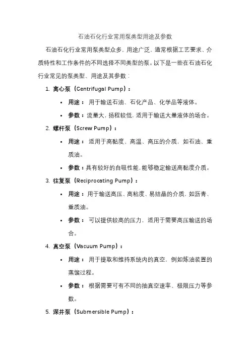
以下是一些在石油石化行业常见的泵类型、用途及其参数:1.离心泵(Centrifugal Pump):•用途:用于输送石油、石化产品、化学品等液体。
•参数:流量大,扬程较低,适用于输送大量液体的场合。
2.螺杆泵(Screw Pump):•用途:适用于高黏度、高温、高压的介质,如石油、重质油。
•参数:具有较好的自吸性能,能够稳定输送高黏度介质。
3.往复泵(Reciprocating Pump):•用途:用于输送高压、高粘度、易结晶的介质,如沥青、重质油。
•参数:可以提供较高的压力,适用于需要高压输送的场合。
4.真空泵(Vacuum Pump):•用途:用于提取和维持系统内的真空,例如炼油装置的蒸馏过程。
•参数:根据需要可有不同的抽真空速率、极限压力等参数。
5.深井泵(Submersible Pump):•用途:主要用于井下提取原油、水、天然气。
•参数:能够在井下工作,适用于深井提油。
6.离心压缩机(Centrifugal Compressor):•用途:用于石油石化行业的气体压缩,例如在裂解装置中。
•参数:适用于大流量、低压比的气体压缩。
7.齿轮泵(Gear Pump):•用途:主要用于输送高粘度的介质,如石蜡、胶体。
•参数:具有良好的自吸性能,适用于要求输送稠密介质的场合。
8.隔膜泵(Diaphragm Pump):•用途:用于输送腐蚀性液体、高粘度介质。
•参数:通过隔膜的运动来完成吸排液体,适用于对泵材料要求较高的场合。
在选择泵类型时,需要考虑工艺条件、介质性质、流量要求、压力要求等因素,并确保所选泵符合相应的技术标准和法规。
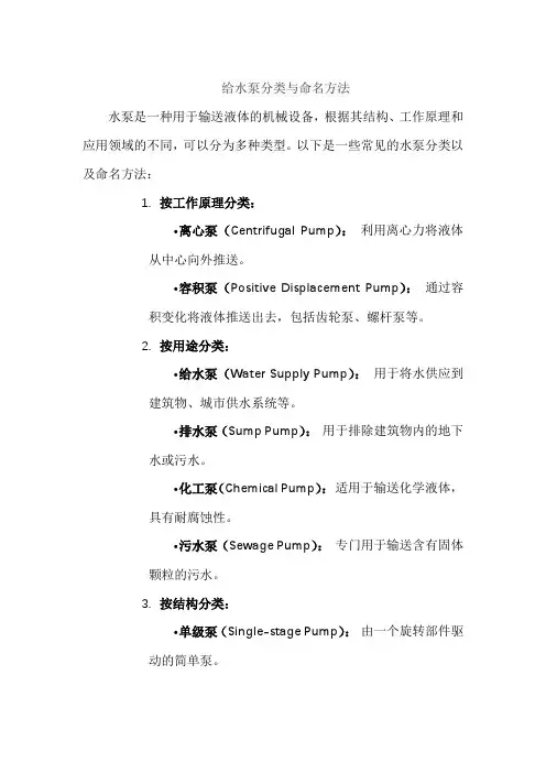
给水泵分类与命名方法水泵是一种用于输送液体的机械设备,根据其结构、工作原理和应用领域的不同,可以分为多种类型。
以下是一些常见的水泵分类以及命名方法:1.按工作原理分类:•离心泵(Centrifugal Pump):利用离心力将液体从中心向外推送。
•容积泵(Positive Displacement Pump):通过容积变化将液体推送出去,包括齿轮泵、螺杆泵等。
2.按用途分类:•给水泵(Water Supply Pump):用于将水供应到建筑物、城市供水系统等。
•排水泵(Sump Pump):用于排除建筑物内的地下水或污水。
•化工泵(Chemical Pump):适用于输送化学液体,具有耐腐蚀性。
•污水泵(Sewage Pump):专门用于输送含有固体颗粒的污水。
3.按结构分类:•单级泵(Single-stage Pump):由一个旋转部件驱动的简单泵。
•多级泵(Multi-stage Pump):包含多个级别的泵,可提供更高的压力。
•潜水泵(Submersible Pump):安装在液体中,用于潜水操作。
4.按驱动方式分类:•电动泵(Electric Pump):通过电动机驱动。
•柴油泵(Diesel Pump):通过柴油发动机驱动。
•手动泵(Manual Pump):通过人力或手动操作。
5.按工作点分类:•定转速泵(Constant Speed Pump):输出流量和扬程保持恒定。
•变速泵(Variable Speed Pump):可通过调整转速来调节流量和扬程。
命名方法通常以泵的类型、用途、结构或驱动方式等为依据,以清晰地描述泵的特性。
例如,“离心给水泵”表示一种用于给水系统的离心泵。
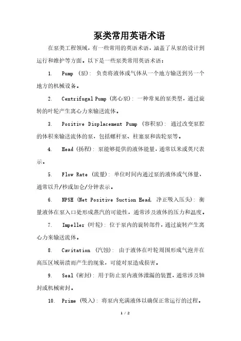
泵类常用英语术语在泵类工程领域,有一些常用的英语术语,涵盖了从泵的设计到运行和维护等方面。
以下是一些泵类常用英语术语:1. Pump (泵): 负责将液体或气体从一个地方输送到另一个地方的机械设备。
2. Centrifugal Pump (离心泵): 一种常见的泵类型,通过旋转的叶轮产生离心力来输送流体。
3. Positive Displacement Pump (容积泵): 通过改变泵腔的体积来输送流体的泵,包括螺杆泵、柱塞泵和齿轮泵等。
4. Head (扬程): 泵能够提供的液体能量,通常以米或英尺表示。
5. Flow Rate (流量): 单位时间内通过泵的液体或气体量,通常以升/秒或加仑/分钟表示。
6. NPSH (Net Positive Suction Head, 净正吸入压头): 衡量液体在泵入口处形成蒸汽的可能性,通常涉及液体的压力和温度。
7. Impeller (叶轮): 位于泵内的旋转部件,通过旋转产生离心力来输送流体。
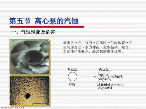
8. Cavitation (汽蚀): 由于液体在叶轮周围形成气泡并在高压区域崩溃而产生的现象,可能对泵造成损害。
9. Seal (密封): 用于防止泵内液体泄漏的装置,通常涉及轴封或机械密封。
10. Prime (吸入): 将泵内充满液体以确保正常运行的过程。
11. Volute (旋流室): 离心泵中用于减缓流体速度并增加压力的蜗壳形状的部分。
12. Throttling (节流): 通过调整阀门或其他装置来控制流体流量的过程。
13. Casing (壳体): 包围泵内部部件的外部壳。
14. Suction Side (吸入侧): 泵的进口侧,涉及液体从源头进入泵的部分。
15. Discharge Side (排出侧): 泵的出口侧,涉及液体从泵流出的部分。
这些术语涵盖了泵类工程中一些常见的概念,对于理解和交流与泵相关的技术信息是很有帮助的。
各种真空泵的工作原理真空泵是一种用于将容器内的气体或蒸汽抽出,从而产生真空的设备。
它在许多工业领域中广泛应用,如化学工业、电子工业、医疗设备等。
不同类型的真空泵有不同的工作原理,下面将介绍几种常见的真空泵及其工作原理。
1. 旋片泵(Rotary Vane Pump)旋片泵是一种常见的机械真空泵,它通过旋转的叶片在泵腔内产生真空。
工作原理如下:泵腔内的叶片与泵腔壁之间形成密封腔,当泵腔旋转时,气体被吸入密封腔,然后被压缩和排出泵腔。
这样循环往复,不断抽出气体,从而产生真空。
2. 涡旋泵(Turbomolecular Pump)涡旋泵是一种高速旋转的分子泵,它通过分子的撞击和反弹来抽取气体。
工作原理如下:涡旋泵内部有多个高速旋转的叶轮,当气体进入泵腔时,叶轮的旋转会使气体分子发生高速运动,从而撞击泵腔壁上的另一侧叶轮。
这种撞击和反弹的过程将气体分子推向泵腔的出口,从而将气体抽出。
3. 根式泵(Roots Pump)根式泵是一种容积式泵,它通过两个旋转的叶轮之间的体积变化来抽取气体。
工作原理如下:根式泵由两个相互啮合的叶轮组成,当叶轮旋转时,它们之间的容积会不断变化。
在吸气阶段,容积增大,气体被吸入;在压缩阶段,容积减小,气体被压缩并排出泵腔。
通过这种循环,气体被连续抽出,从而形成真空。
4. 离心泵(Centrifugal Pump)离心泵是一种利用离心力将气体抽出的泵。
工作原理如下:离心泵内部有一个高速旋转的叶轮,当气体进入泵腔时,叶轮的旋转会产生离心力,将气体推向泵腔的出口。
这样,气体被连续抽出,从而形成真空。
以上是几种常见的真空泵及其工作原理。
不同类型的真空泵适用于不同的应用场景,选择合适的真空泵可以提高工作效率和产品质量。
在实际应用中,还需要考虑泵的抽气速度、抽气量、最终真空度等参数,以及泵的维护和保养等因素。
通过合理选择和使用真空泵,可以满足各种工业领域的真空需求。
什么是离心泵什么是离心泵?离心泵(centrifugal pump)是指靠叶轮旋转时产生的离心力来输送液体的泵。
离心泵利用高速旋转的叶轮叶片带动水转动,将水甩出,从而达到输送的目的。
水泵在启动前,必须使泵壳和吸水管内充满水,然后启动电机,使泵轴带动叶轮和水做高速旋转运动,水发生离心运动,被甩向叶轮外缘,经蜗形泵壳的流道流入水泵的压水管路。
离心泵有立式、卧式、单级、多级、单吸、双吸、自吸式等多种形式。
叶轮内的液体受到叶片的推动而与叶片共同旋转,由旋转而产生的离心力,使液体由中心向外运动,并获得动量增量。
离心泵的基本构造是由八部分组成的,分别是:叶轮,泵体,泵盖,挡水圈,泵轴,轴承,密封环,填料函,轴向力平衡装置。
叶轮是离心泵的核心部分,它转速高输出力大。
泵体也称泵壳,它是水泵的主体。
起到支撑固定作用,并与安装轴承的托架相连接。
2离心泵的起动离心泵起动及操作1.起动油离心泵,注意泵轴的转向是否正确。
2.注意转动时有无不正常的声响和振动。
3.注意压力表及真空表读数,起动后当压力表及真空表的读数经过一段时间的波动而指示稳定后,说明泵内已经上液,齿轮油泵进入正常输油作业。
4.在离心泵进入正常输油作业前即自吸(或扫舱)过程中,应特别注意泵内油温升高状况,如果这个过程过长,泵内油温过高,则停泵检查其原因。
5.如果泵内液体温度过高而引起自吸困难,那么可以暂时停机,利用吐出管路中的液体倒流回泵内或向泵体上的加储液口处直接向泵内补充液体,使泵内液体降温,然后起动即可。
6.调节出口控制阀,使压力表读数指到规定区域,避免齿轮油泵在规定区域的下限范围内工作,以防因轴功率过大而引起电动机过载,或因流量过大而使泵产生汽蚀,影响泵的正常运转,使泵激烈振动,发出噪声。
输送各种油料时的压力的使用范围。
7.离心泵在工作过程中如发生激烈振动和噪声,有可能是泵发生汽蚀所致,汽蚀产生的原因有两种:一是进口管流速过大,二是吸程过高。
流速过大时可调节出口控制阀,升高压力表读数,在进口管路有堵塞时则应及时排除;吸程太高时可适当降低泵的安装高度。
离心泵组成离心泵组成离心泵(centrifugal pump)是指靠叶轮旋转时产生的离心力来输送液体的泵。
结构组成离心泵的基本构造是由六部分组成的分别是叶轮,泵体,泵轴,轴承,密封环,填料函。
1、叶轮是离心泵的核心部分,它转速高出力大,叶轮上的叶片又起到主要作用,叶轮在装配前要通过静平衡实验。
叶轮上的内外表面要求光滑,以减少水流的摩擦损失。
2、泵体也称泵壳,它是水泵的主体。
起到支撑固定作用,并与安装轴承的托架相连接。
3、泵轴的作用是借联轴器和电动机相连接,将电动机的转矩传给叶轮,所以它是传递机械能的主要部件。
4、滑动轴承使用的是透明油作润滑剂的,加油到油位线。
太多油要沿泵轴渗出,太少轴承又要过热烧坏造成事故!在水泵运行过程中轴承的温度最高在85度,一般运行在60度左右。
5、密封环又称减漏环。
6、填料函主要由填料、水封环、填料筒、填料压盖、水封管组成。
填料函的作用主要是为了封闭泵壳与泵轴之间的空隙,不让泵内的水流流到外面来也不让外面的空气进入到泵内,始终保持水泵内的真空。
当泵轴与填料摩擦产生热量就要靠水封管注水到水封圈内使填料冷却,保持水泵的正常运行。
所以在水泵的运行巡回检查过程中对填料函的检查是特别要注意,在运行600个小时左右就要对填料进行更换。
基本构造离心泵的基本构造是由八部分组成的,分别是:叶轮,泵体,泵盖,挡水圈,泵轴,轴承,密封环,填料函,轴向力平衡装置。
1、叶轮是离心泵的核心部分,它转速高输出力大。
2、泵体也称泵壳,它是水泵的主体。
起到支撑固定作用,并与安装轴承的托架相连接。
3、泵轴的作用是借联轴器和电动机相连接,将电动机的转矩传给叶轮,所以它是传递机械能的主要部件4、密封环又称减漏环。
5、填料函主要由填料,不让泵内的水流流到外面来也不让外面的空气进入到泵内。
始终保持水泵内的真空!当泵轴与填料摩擦产生热量就要靠水封管注水到水封圈内使填料冷却!6、轴向力平衡装置,在离心泵运行过程中,由于液体是在低压下进入叶轮,而在高压下流出,使叶轮两侧所受压力不等,产生了指向入口方向的轴向推力,会引起转子发生轴向窜动,产生磨损和振动,因此应设置轴向推力轴承,以便平衡轴向力。
中开离心泵结构范文
离心泵(Centrifugal pump)是较为常见的水泵之一,广泛应用于工业和民用领域。
离心泵结构主要由以下几个部分组成:进口和出口法兰、泵体、叶轮、轴、轴承和密封件。
进口和出口法兰:离心泵的进水和出水口通常采用法兰连接方式,进口法兰通常位于泵的中心位置,以便使液体顺利进入泵体;出口法兰则位于泵体的侧面,用于将压缩的液体从泵体中排出。
泵体:泵体是离心泵的主要支撑部分,通常由铸铁或不锈钢等材料制成。
泵体内部的流道和腔室通过进口法兰连接到进水的管道,使液体能够进入泵体并顺利流动。
叶轮:离心泵的叶轮是泵体内部的转动部分,通常由金属材料制成。
叶轮的设计和形状决定了泵的流量和扬程,可以通过更换不同类型的叶轮来适应不同的工况需求。
轴:离心泵的叶轮通过轴与电动机连接,轴通常由高强度的不锈钢材料制成,以支撑叶轮的旋转运动,并传导电动机的动力。
轴承:轴承是离心泵的重要组成部分,用于支撑轴的旋转,并降低摩擦和磨损。
常见的轴承类型包括滑动轴承和滚动轴承,滚动轴承通常具有较高的转速和承载能力。
密封件:离心泵的密封件用于避免液体从泵体内部泄漏到泵外,以确保泵的正常工作。
常见的密封方式包括填料密封和机械密封。
填料密封通过填充密封材料(如软树脂)在泵轴和泵体之间形成密封,而机械密封则通过机械装置(如密封圈)实现密封。
总的来说,离心泵的结构相对简单,但各个部件之间的配合和工艺要求十分严苛,需要保证泵的正常运行和长寿命。
此外,离心泵还有许多补充设备和部件,如进水过滤器、排气阀门和压力表等,以提高泵的性能和安全性。
离心泵的工作原理及主要部件性能参数离心泵——生产中应用最为广泛,着重介绍。
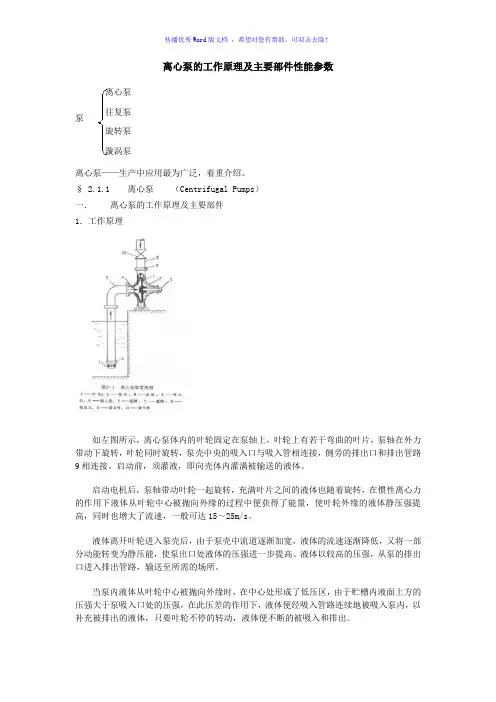
§ 2.1.1离心泵(Centrifugal Pumps)一.离心泵的工作原理及主要部件1.工作原理如左图所示,离心泵体内的叶轮固定在泵轴上,叶轮上有若干弯曲的叶片,泵轴在外力带动下旋转,叶轮同时旋转,泵壳中央的吸入口与吸入管相连接,侧旁的排出口和排出管路9相连接。
启动前,须灌液,即向壳体内灌满被输送的液体。
启动电机后,泵轴带动叶轮一起旋转,充满叶片之间的液体也随着旋转,在惯性离心力的作用下液体从叶轮中心被抛向外缘的过程中便获得了能量,使叶轮外缘的液体静压强提高,同时也增大了流速,一般可达15~25m/s。
液体离开叶轮进入泵壳后,由于泵壳中流道逐渐加宽,液体的流速逐渐降低,又将一部分动能转变为静压能,使泵出口处液体的压强进一步提高。
液体以较高的压强,从泵的排出口进入排出管路,输送至所需的场所。
当泵内液体从叶轮中心被抛向外缘时,在中心处形成了低压区,由于贮槽内液面上方的压强大于泵吸入口处的压强,在此压差的作用下,液体便经吸入管路连续地被吸入泵内,以补充被排出的液体,只要叶轮不停的转动,液体便不断的被吸入和排出。
泵离心泵旋转泵漩涡泵往复泵由此可见,离心泵之所以能输送液体,主要是依靠高速旋转的叶轮,液体在离心力的作用下获得了能量以提高压强。
气缚现象:不灌液,则泵体内存有空气,由于ρ空气<<ρ液,所以产生的离心力很小,因而叶轮中心处所形成的低压不足以将贮槽内的液体吸入泵内,达不到输液目的。
通常在吸入管路的进口处装有一单向底阀,以截留灌入泵体内的液体。
另外,在单向阀下面装有滤网,其作用是拦阻液体中的固体物质被吸入而堵塞管道和泵壳。
启动与停泵:灌液完毕后,此时应关闭出口阀后启动泵,这时所需的泵的轴功率最小,启动电流较小,以保护电机。
启动后渐渐开启出口阀。
停泵前,要先关闭出口阀后再停机,这样可避免排出管内的水柱倒冲泵壳内叶轮,叶片,以延长泵的使用寿命。
离心泵特性曲线
离心泵特性曲线(Centrifugal pump performance curve)是描述离心泵在不同工作条件下流量、扬程、效率和功率
等性能参数的变化关系的曲线。
离心泵特性曲线通常由以下几个要素构成:
1. 流量(Flow):流经离心泵的液体体积或质量的量度,
通常以升/秒或立方米/小时表示。
2. 扬程(Head):液体在离心泵内获得的压力能量,通常以米或千帕表示。
3. 效率(Efficiency):离心泵将输入的功率转化为输出的液体动能的比例。
效率通常以百分比表示。
4. 功率(Power):离心泵所需的电功率或机械功率,通常以千瓦或马力表示。
离心泵特性曲线一般由实验测量得到,根据不同工作条件下的流量、扬程和功率等数据绘制而成。
典型的离心泵特性曲线通常呈现出以下特点:
1. 最大扬程点(Maximum Head Point):离心泵在某一流量下能够提供的最大扬程。
该点通常是离心泵特性曲线上的最高点,也是离心泵的额定扬程。
2. 最大效率点(Maximum Efficiency Point):离心泵在某一流量下能够达到的最高效率。
该点通常是离心泵特性曲线上的效率最大值点。
3. 关闭阻塞点(Shut-off Head Point):离心泵在流量为零时的扬程。
该点通常是离心泵特性曲线上的最低点。
离心泵特性曲线的形状和特点对于选型和运行离心泵都具有重要的参考价值,可以帮助用户了解离心泵在不同工况下的性能和适用范围,并进行合理的运行和维护。
附录(一):Optimizing centrifugal pump operationCentrifugal pump operation is more than switching the pump on and directing the discharge flow to the required delivery point. This holds true even when a control value is installed in the discharge line for the purpose of flow or level control .A few very essential operating guidelines must be adhered to if early bearing or seal failure, premature erosion of internal wetted surfaces, or metal-to-metal contact of internal rotating and stationary surfaces, is to be avoided. In this article, Stan Shiels addresses the fundamentals of proper centrifugal pump operation and the most common areas of improper centrifugal pump operation. It is assumed that the pump has been successfully commissioned.The most common cause of centrifugal pump failure, separate from those causes associated with maintenance and/or design, but associated with how the pumps are operated may be summarized as follows:1. Insufficient suction pressure to avoid cavitation.2. Excessively high flow rate for the net positive suction head available (NPSHA).3. Prolonged operation at lower than acceptable flow rates.4. Operation of the pump at zero or near zero flow rate.S. Improper operation of the pump in parallel.6. Failure to maintain adequate lubrication for the bearings.7. Failure to maintain satisfactory flushing to mechanical seals.Insufficient suction pressure to avoid cavitation.While the provision of sufficient suction pressure to avoid cavitation may seem straightforward, requiring only that the net positive suction head available(NPSHA) be always greater than or equal to the net positive suction head required (NPSHR) by the pump, some misconceptions need to be revealed. When the pump manufacturer develops the pump's NPSHR curve, the calculated values of NPSHR are for conditions where theexpected head (as determined by the previously performed pumphydraulic performance test) has fallen of by 3% for that specific flow rate. This means that mild cavitation will exist when the NPSHA equals the NPSHR. Because of this a comfort margin of 3 feet, or 1meter, isrecommended, when determining the minimum acceptable NPSH margin:(NPSHA-NPSHR).The following piping faults will require an NPSH margin greater than 3 feet(1 meter) to ensure the absence of cavitation.~Where the inlet piping configuration is such that a number of 90 degree turns occur, in different planes, fairly close to the pump suction, the resultant fluid swirl will cause cavitation to occur, on occasion, even when the NPSH margin is 2 to 3 feet.~Where an eccentric inlet reducer is positioned in the pipe such that itforces asymmetric flow into the suction of a double suction pump. The side of the double suction impeller that receives the disproportionately higher percentage of the total flow will incur cavitation at an NPSHA much higher than the NPSHR indicated on the manufacturer's test curve.Excessively high flow rate for the NPSH availableBased upon the simple fact that NPSHA decreases as flow rate increases, and NPSHR increases as flow rate increases, there should be considerable effort place on ensuring that the point of intersection of these two parameters is not reached. This concept is illustrated in Figurel.Many centrifugal pumps are installed in a system, which cannot pro vide adequate suction pressure to avoid cavitation, if operated at flow rates much above their best efficiency point (BEP). It is probably never intended to operate these pumps in such a region, but transient conditions can often lead to intended operation at much higher than expected flow rates. One example is the case where a recycle control value has been installed to ensure that the pump is not operated below a minimum acceptable flow rate. At very low or zero process flow the recycle control value may attain a position of greater than 50% open. This of itself is not a problem, but the extremely high flow rate may occur when the process control value is again asked to open, and does so rather quickly. When the process control valve is faster acting than the recycle control valve, the combined process and recycle flows may necessitate a higher NPSHR than the suction system can provide.Manual operation must also be handled carefully when simple transfer operations between vessels is called for. At the start of such operation the receiving vessel may have a very high level. This leads to a negative static head, which can lead to an initial high flow rate until the level rises in the discharge vessel. This is a particularly risky operation where piping system resistance is low on the discharge side, but a relatively long section of suction piping exists.Prolonged operation at lower than acceptable flow ratesA centrifugal pump is most comfortable operating between 85% and 110% of its best efficiency point (BEP). However, by far the great majority of centrifugal pumps are forced to operate outside of this range. The degree to which it is acceptable to operate outside of this range is a function of two primary parameters:Suction Specific Speed (Ss) and Specific Speed (S). These parameters may be calculated for a pump provided the following data is known: For maximum diameter impeller:BEP FlowNPSHR at BEP FlowHead at BEP FlowPump Operating Speed (RPM)The following formulae allow Ss and S to be calculated:()0.50.750.50.75()()()bep bepbep bep SpecificSpeed S REP Q H SuctionSpecificSpeed Ss RPE Q NPSHR=⨯÷=⨯÷Where: QPM is pump rotational speed in revolutions per minute.bep Q flow at BEP for maximum diameter impeller.bep H is pump head at BEP for maximum diameter impeller.bep NPSHR is the pump net positive head required at BEP for maximum diameter impeller.The acceptable minimum continuous flow rate, which a centrifugal pump can be expected to endure without incurring damage or premature failure is also affected by a number of other parameters: such as, impeller head, fluid specific gravity , and percentage of total running time spent at the lower flow rate. When the pump's specific speed and suction specific speed are known the approximate percentage of the pump's maximum impeller diameter BEP flow at which suction recirculation can be expected to occur may be estimated.From this estimate the approximate minimum acceptable continuous flow rate for that specific pump may be estimated. Impeller geometry can be optimized to improve on initial estimates and, when conditions are marginal, it is always advisable to consult with the manufacturer's application engineer before deciding on the acceptable minimum continuous flow rate.A subsequent article can expend further on this much debated area of centrifugalpump operation. In the interim it is suggested that pump users request the minimum "stable" continuous flow rate recommended from the pump manufacturer, based upon the onset of flow instability .Impeller geometry can impact the "Cavitation Coefficient" which is defined by the following formula:211(2)u g NPSH u δ=⨯÷Where1u δ is the cavitation coefficientg is the gravitation constantNPSH is net positive suction head1u is fluid circumferential velocity at impeller entryThis is a dimensionless coefficient and would be valid for all geometrically similar pumps, independent of their size and speed of rotation.Operation of the pump at zero or near zero flow rateCentrifugal pumps are often used to pump out vessels, often to zero level. The pumps can, at times, be left unattended. If the level is allowed to fall to the point where the pump is allowed to run dry , failure of the mechanical seal will often follow rapidly. In such applications even a small recycle flow back to the suction vessel will not alleviate the problem, as the pump will still be able to empty the vessel. Many such applications are best protected by the installation of dual pressurized mechanical seals which will remain lubricated even during periods of completely dry running. In non hazardous applications a pump sealed with packing will survive better if the packing is lubricated from an external source; the source must, of course, be compatible with the fluid being pumped.Where batch delivery is normal operation, such that the pump will operate for long periods, but delivery is intermittent, a small continuous recycle flow back to the suction source will help to protect the pump during periods when delivery stops (typically by closing the delivery valve). Lack of some of the recycle protection for a centrifugal pump, which will see periods of zero flow, will certainly cause frequent pump failure. Any centrifugal pump operated at zero flow for even a few minutes will vapour temperature. It is worth remembering that once a pump has vapour-locked it will not generate any noticeable discharge pressure differential. Usually it is necessary to stop the pump and allow the gas to condense back into liquid, before pumping can resume.Improper operation of the pump in parallel.This topic has been covered in detail in a previous "Pump Academy" article, but the basics are worthy of mention in terms general centrifugal pump operating philosophy. The following principles should be applied to any operation of centrifugal pumps, which requires either continuous or intermittent parallel operation.~Shut-off heads of all pumps operating in parallel should be comparable typically as close as possible, with difference of no more than 2%or 3% recommended~V ery flat performance curves in one or more of the pumps operating in parallel is to be avoided;a drop of 10% to 20% between the shut-off and rated points is recommended. The point of hydraulic shut-off of the more worn pump of two initially identical pumps operating in parallel is shown in Figure 2, for high head rise to shut-off and low head rise to shut-off.~Multistage pumps, or expensive single-stage or two-stage pumps designed to operate in parallel, should be protected by low flow shut-down devices to avoid severe damage from occurring at transient low combined flow conditions. While the pumps may be identical, performance differences occur over time, and the better performing pump will effectively "shut-off" the weaker pump below a specific combined flow rate. The low flow shut-down will prevent the major damage that often results from such occurrences.~inlet and discharge piping configurations and lengths should be comparable between the pump and the suction and discharge headers. Proper piping configuration for pumps operating in parallel should include suction and discharge headers of larger diameter than the lines leading to and from the individual pumps. Differences in suction and/or discharge piping configuration will always lead to a disparity in pump flow rates.Failure to maintain adequate lubrication for the bearingsThis is a simple statement and sounds too fundamental to be ignored, but, even among those diligent pump operators who strive to maintain adequate lubrication, some inadvertent mistakes are made. Lubrication of rolling element bearings is the subject here. They may be oil lubricated or grease lubricated. The complete topic requires more attention than can be afforded in this text, but the basic essentials always hold true and can only be ignored at the risk of early pump failure.Oil lubrication is of three basic types: forced feed with a pressurized filtered and cooled oil supply to the bearings in a closed loop system; oil bath; and oil mistThe forced feed system is the most complicated and usually incorporates a low oil pressure shutdown protection; it is normally only present in large multistage pump installations. The key areas of concern are:~Maintenance of the correct viscosity of the oil and periodic monitoring for changes in viscosity and/or Total Acid Number (TAN) and the presence of water in the oil.~On occasion ferrographic analysis for the presence of wear particles helps to diagnose impendent bearing damage.~Lube oil cooler performance decline may lead to elevated temperatures and periodic oil temperature monitoring is also essential.~Oil filter differential pressure and main oil supply pressure to the bearings also requires frequent attention.A housing for oil bath lubrication normally incorporates a constant level oiler, although some pump users have chosen to seal their bearing housing and use synthetic oil, changing the oil only once every two or three years. For those bearing housings incorporating a constant level oiler the following basic principles apply:~Use of the correct viscosity oil for the operating temperature of the bearing (refer to the bearing manufacturer's literature).~Maintenance of a reserve of oil in the constant level oiler.~Clean storage of the make-up oil to prevent foreign material and/or moisture from entering the bearings.~Observance of the deterioration in the oiler level一remember, oilers whose level never falls over time may have a blocked connection between the oiler and the bearing housing.Oil mist lubrication requires that the same viscosity oil be used as for oil bath lubrication. On occasion a grade lighter oil may be used as the oil is being constantly replenished, although this approach should be taken with caution. While most oil mist systems incorporate an alarm for loss of oil mist pressure, each bearing housing should be periodically checked to confirm adequate venting of oil mist from the housing, and for proper condensation and drainage of bearing housing oil mist condensate collection pots.Grease lubrication of rolling element bearings requires proper attention to the following:~The type of grease used. A stiffer grease for higher speeds (3000 RPM and above) and a softer grease for lower speeds.~The grease should essentially contain the same viscosity of oil in it as that required for oil bath luibrication.~The amount of grease. This is of particular importance where pump operators are responsible for regreasing of bearings, as a major cause of failure of grease lubricated pump bearings is overgreasing. The idea that more is better is very wrong here.~Compatibility of greases. When regreasing it is essential that the grease to be added is compatible with the originally installed grease.As is the case for oil type selection, it is recommended that the bearing applications engineering department be consulted, when in doubt about which grease is best for each specific application.Failure to maintain satisfactory flushing to mechanical sealsThe flushing plan for a mechanical seal is the means of controlling the environment in which the seal operates. It follows then that any event that alters the intended flushing flow parameters will alter the seal's environment and may lead to seal failure. The following parameters, for some of the most commonly utilized seal flushing arrangements, should be regularly monitored for mechanical seals:Pump discharge flush to the seal to confirm that the temperature is correct. The dischargeflush should be at the same temperature as the pump discharge flow. In hot service a cooler flush will indicate lack of sufficient flow; this is often the only means available of checking flow, as most discharge flush plans do not have a flow indication.Suction flush from the seal cavity to the pump suction should also be checked for temperature. This may require that the temperature be checked initially to set a "benchmark." Any noticeable increase in this flush return to the pump suction may indicate a flow restriction.Cooled discharge flushes require adequate cooling to attain the required flush temperature. Discharge flush coolers foul over time and often the flush temperature is allowed to rise to the point of seal failure before cooler fouling is discovered. Both the cooling water differential temperature and the flush supply temperature to the seal should be monitored and the cooler replaced of cleaned before fouling progresses too far.Dual unpressurized seals rely on a head of liquid in a seal pot to provide a small pressure differential between the seal interspace and atmosphere. Both the seal pot level and the seal pot pressure should be observed for signs of change. Dualunpressurized seals are often utilized in volatile fluid service, where the vapour pressure is above atmospheric and any normal primary seal vapour leakage can be vented through the seal pot orifice to a safe collection point; a noticeable increase in seal pot pressure would indicate a primary (inner) seal failure. A reduction in seal pot level would indicate an outer seal failure.Dual pressurized seals incorporating a seal pot similarly should be monitored. The seal pot pressure must be maintained at a pressure above the seal cavity pressure for satisfactory seal operation. A reduction in seal pot level will indicate either a primary or or outer seal failure; further observation for obvious leakage of the outer seal is required to determine which one has failed. Loss of seal pot pressure may indicate a failure of the pressure blanketing system. Alarms are usually incorporated in dual seal systems incorporating seal pots. It is still advisable to monitor these parameters to allow early warning of loss of adequate seal flushing.Dual pressurized seals utilizing a flow-through barrier fluid system should have regular checks carried out for barrier fluid inlet and outlet temperatures and pressures. If the barrier fluid return pressure is allowed to drop to a value below the seal cavity (pump side) pressure, seal failure will follow in a pump media containing abrasives. Not all such systems have flow indication and a rise in differential temperature will usually indicate an increase in leakage rate of the inner seal, but could signify a reduction in barrier fluid flow rate; where flow rate is not subject to change it normally indicates an increase in inner seal leakage rate. A check of barrier fluid inlet pressure to the seal will assist in the diagnosis. A drop in barrier fluid return pressure, usually accompanied by arise in return temperature, is almost always associated with an inner seal failure.A last wordWhile there are many more causes of operational failure of centrifugal pumps, this discussion has dealt with the most frequently contributing areas. The operators of centrifugal pumps must extend their scope into the area of "ownership: Operators need to become familiar with tow these pumps operate, their key areas to monitor, and what to look for. It could also be said that many large process plants, which operate a large number of centrifugal pumps, do not provide sufficient pump training to permit the operating staff to understand key operating principles and satisfactory monitoring guidelines. We enjoy driving our automobiles. When have maintenance carried out: oil change, engine tune-up, transmission checked, brakes overhauled,tires renewed, fluid levels checked, hoses replaced, etc. most of us do not drive our cars until the oil breaks down completely and seizes the engine, the coolant hose blows, the brakes fail, the tires lose their tread, or the transmission fails. Periodic checks allow us to avoid such failures. We own our cars and do not want to incur the cost and inconvenience of such failures. A similar frame of mind toward centrifugal pump operation, supported by a proper program of operator training will pay dividends in terms of pump reliability and the cost of pump operation, and avoid some costly process debits.附录(二):优化离心泵的操作操作离心泵不仅指打开水泵阀门、接通排水管、导出排放液体到规定传输点还包括在排水管中安装控制阀以控制调节流量和液位等为了避免早期轴承或密封失效、内部潮湿表面过早浸蚀、以及内部旋转和固定部分金属表面发生摩擦等状况发生,在操作离心泵时须遵循一定的操作原则, 本文中,Stan Shiels给出了离心泵合理操作的基本法则和不正确使用离心泵的常见误区本文假设离心泵正常投入运行。
离心泵结构工作原理Centrifugal pumps are a common type of water pump used in various industries and applications. They work by converting mechanical energy from a motor into kinetic energy to move water through the pump. 离心泵是各种领域和应用中常见的一种水泵类型。
它们通过将电机的机械能转换为动能来推动水通过泵。
The structure of a centrifugal pump consists of several key components, including an impeller, a casing, and a shaft. The impeller is the rotating component of the pump that imparts kinetic energy to the fluid. The casing is the stationary part that surrounds the impeller and directs the flow of water. The shaft connects the impeller to the motor, transferring the rotational energy. 离心泵的结构包括几个关键部件,包括叶轮、壳体和轴。
叶轮是泵的旋转部件,为流体提供动能。
壳体是围绕叶轮的静止部件,引导水流。
轴连接叶轮和电机,传递旋转能量。
One of the main advantages of centrifugal pumps is their simple design and ease of maintenance. They are also known for their high efficiency in moving water over long distances. However, they arenot as effective in handling high-viscosity fluids or solids. 离心泵的主要优点之一是其简单的设计和易于维护。