基于STM32单片机的增量式编码器模拟装置设计
- 格式:pdf
- 大小:752.67 KB
- 文档页数:3

基于STM32的磁编码器的设计
陈文浩;朱礼尧;迟涵文;刘雯;赵志永;邓仕杰;黄彤津
【期刊名称】《电子测量技术》
【年(卷),期】2015(0)6
【摘要】选用巨磁阻传感器作为敏感元件,设计一款基于STM32微控制器的磁编码器。
由正交放置在圆柱状磁体下方的4个巨磁阻传感器输出两路正交电压信号,该电压信号经过调理电路滤波、放大,采用STM32微处理器对放大后的两路电压信号进行模数转换,然后对转换后的数字量进行校正、辩向和查表等来完成信号处理,输出准确的旋转角度值,并根据需要灵活选择合适的编码器输出方式。
试验结果表明,磁编码器具有较高的检测精度以及实时性。
【总页数】6页(P22-26)
【关键词】STM32微处理器;磁编码器;巨磁阻传感器;算法运算
【作者】陈文浩;朱礼尧;迟涵文;刘雯;赵志永;邓仕杰;黄彤津
【作者单位】杭州电子科技大学电子信息学院
【正文语种】中文
【中图分类】TP212
【相关文献】
1.基于STM32的变频器+编码器精确定位控制系统设计 [J], 吴涛;李勇波;杨靖
2.基于STM32单片机的增量式编码器模拟装置设计 [J], 徐洋;余辉;黄敬贵
3.基于STM32的绝对编码器信号转换为增量编码器信号装置设计 [J], 沈宝诚; 吴
剑飞; 朱嘉
4.基于STM32的增量式编码器测速设计及实验验证 [J], 鲁伟;刘士兴;孙操;李隆
5.基于Arduino的磁编码器轴角解算系统设计 [J], 赵磊;曹广忠;梁芳萍;孙俊缔;胡勇;王芸
因版权原因,仅展示原文概要,查看原文内容请购买。
【分享】增量式PID的stm32实现,整定过程1感谢大家最近的帮忙,让我顺利做完增量PID功能,虽然PID不是什么牛逼的东西,但是真心希望以后刚刚接触这块的人能尽快进入状态。
也下面我分享一下近期的这些工作吧。
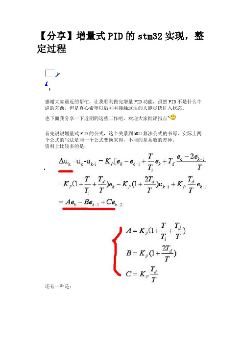
欢迎大家批评指点~首先说说增量式PID的公式,这个关系到MCU算法公式的书写,实际上两个公式的写法是同一个公式变换来得,不同的是系数的差异。
资料上比较多的是:•还有一种是:感觉第二种的Kp Ki Kd比较清楚,更好理解,下面介绍的就以第二种来吧。
(比例、积分、微分三个环节的作用这里就详细展开,百度会有很多)硬件部分:控制系统的控制对象是4个空心杯直流电机,电机带光电编码器,可以反馈转速大小的波形。
电机驱动模块是普通的L298N模块。
芯片型号,STM32F103ZET6软件部分:PWM输出:TIM3,可以直接输出4路不通占空比的PWM波PWM捕获:STM32除了TIM6 TIM7其余的都有捕获功能,使用TIM1 TIM2 TIM4 TIM5四个定时器捕获四个反馈信号PID的采样和处理:使用了基本定时器TIM6,溢出时间就是我的采样周期,理论上T越小效果会越好,这里我取20ms,依据控制对象吧,如果控制水温什么的采样周期会是几秒几分钟什么的。
上面的PWM输出和捕获关于定时器的设置都有例程,我这里是这样的:TIM3输出四路PWM,在引脚 C 的 GPIO_Pin_6 | GPIO_Pin_7 | GPIO_Pin_8 | GPIO_Pin_9输出四路捕获分别是TIM4 TIM1 TIM2 TIM5 ,对应引脚是:PB7 PE11 PB3 PA1高级定时器tim1的初始化略不同,它的中断”名称“和通用定时器不同,见代码:1./*功能名称IM3_PWM_Init(u16 arr,u16 psc)2.描述TIM3产生四路PWM3.*/4.void TIM3_PWM_Init(u16 arr,u16 psc)5.{6. GPIO_InitTypeDef GPIO_InitStructure;7. TIM_TimeBaseInitTypeDef TIM_TimeBaseStructure;8. TIM_OCInitTypeDef TIM_OCInitStructure;9.10.11. RCC_APB1PeriphClockCmd(RCC_APB1Periph_TIM3,ENABLE);12. RCC_APB2PeriphClockCmd(RCC_APB2Periph_GPIOC| RCC_APB2Periph_AFIO, ENABLE); //使能GPIO外设和AFIO复用功能模块时钟使能13.14. GPIO_PinRemapConfig(GPIO_FullRemap_TIM3, ENABLE);//Timer3全映射 GPIOC->6,7,8,9//用于TIM3的CH2输出的PWM通过该LED显示15.16. //设置该引脚为复用输出功能,输出TIM3 CH1 CH2 CH3 CH4 的PWM脉冲波形17. GPIO_InitStructure.GPIO_Pin =GPIO_Pin_6 |GPIO_Pin_7 | GPIO_Pin_8 | GPIO_Pin_9; //初始化GPIO18. GPIO_InitStructure.GPIO_Mode =GPIO_Mode_AF_PP; //复用推挽输出19. GPIO_InitStructure.GPIO_Speed =GPIO_Speed_50MHz;20. GPIO_Init(GPIOC, &GPIO_InitStructure);21. GPIO_ResetBits(GPIOC,GPIO_Pin_6 | GPIO_Pin_7 |GPIO_Pin_8 | GPIO_Pin_9);//默认电机使能端状态:不使能22.23. TIM_TimeBaseStructure.TIM_Period = arr; //设置在下一个更新事件装入活动的自动重装载寄存器周期的值24. TIM_TimeBaseStructure.TIM_Prescaler =psc; //设置用来作为TIMx时钟频率除数的预分频值这里是72分频,那么时钟频率就是1M25. TIM_TimeBaseStructure.TIM_ClockDivision = 0; //设置时钟分割:TDTS = Tck_tim26. TIM_TimeBaseStructure.TIM_CounterMode =TIM_CounterMode_Up; //TIM向上计数模式27. TIM_TimeBaseInit(TIM3, &TIM_TimeBaseStructure);//根据TIM_TimeBaseInitStruct中指定的参数初始化TIMx的时间基数单位28.29.30. TIM_OCInitStructure.TIM_OCMode =TIM_OCMode_PWM1; //选择定时器模式:TIM脉冲宽度调制模式1 31. TIM_OCInitStructure.TIM_OutputState =TIM_OutputState_Enable; //比较输出使能32. TIM_OCInitStructure.TIM_Pulse = 0; //设置待装入捕获比较寄存器的脉冲值33. TIM_OCInitStructure.TIM_OCPolarity =TIM_OCPolarity_High; //输出极性:TIM输出比较极性高34.35. TIM_OC1Init(TIM3, &TIM_OCInitStructure); //根据TIM_OCInitStruct中指定的参数初始化外设TIMx36. TIM_OC1PreloadConfig(TIM3,TIM_OCPreload_Enable); //使能TIMx在CCR1上的预装载寄存器37.38.39. TIM_OC2Init(TIM3, &TIM_OCInitStructure); //根据TIM_OCInitStruct中指定的参数初始化外设TIMx40. TIM_OC2PreloadConfig(TIM3,TIM_OCPreload_Enable); //使能TIMx在CCR2上的预装载寄存器41.42. TIM_OC3Init(TIM3, &TIM_OCInitStructure); //根据TIM_OCInitStruct中指定的参数初始化外设TIMx43. TIM_OC3PreloadConfig(TIM3,TIM_OCPreload_Enable); //使能TIMx在CCR3上的预装载寄存器44.45. TIM_OC4Init(TIM3, &TIM_OCInitStructure); //根据TIM_OCInitStruct中指定的参数初始化外设TIMx46. TIM_OC4PreloadConfig(TIM3,TIM_OCPreload_Enable); //使能TIMx在CCR4上的预装载寄存器47.48. TIM_ARRPreloadConfig(TIM3, ENABLE); //使能TIMx在ARR上的预装载寄存器49.50.51. TIM_Cmd(TIM3, ENABLE); //使能TIMx外设52.53.54.}55.56.57.58./*功能名称TIM4_PWMINPUT_INIT(u16 arr,u16 psc)59. 描述PWM输入初始化*/60.61.void TIM4_PWMINPUT_INIT(u16 arr,u16 psc)62.{63.64. TIM_TimeBaseInitTypeDef TIM_TimeBaseStructure; //TIM的初始化结构体65. NVIC_InitTypeDefNVIC_InitStructure; //中断配置66. TIM_ICInitTypeDef TIM4_ICInitStructure;//TIM4 PWM配置结构体67. GPIO_InitTypeDefGPIO_InitStructure; / /IO口配置结构体68.69. RCC_APB1PeriphClockCmd(RCC_APB1Periph_TIM4,ENABLE); //Open TIM4 clock70. RCC_APB2PeriphClockCmd(RCC_APB2Periph_GPIOB,ENABLE); //open gpioB clock71.72. GPIO_InitStructure.GPIO_Pin =GPIO_Pin_7; //GPIO 773. GPIO_InitStructure.GPIO_Mode =GPIO_Mode_IPU; //上拉输入74. GPIO_InitStructure.GPIO_Speed = GPIO_Speed_50MHz;75. GPIO_Init(GPIOB, &GPIO_InitStructure);76.77. TIM_TimeBaseStructure.TIM_Period = arr; //设置在下一个更新事件装入活动的自动重装载寄存器周期的值78. TIM_TimeBaseStructure.TIM_Prescaler =psc; //设置用来作为TIMx时钟频率除数的预分频值79. TIM_TimeBaseStructure.TIM_ClockDivision = 0; //设置时钟分割:TDTS = Tck_tim80. TIM_TimeBaseStructure.TIM_CounterMode =TIM_CounterMode_Up; //TIM向上计数模式81. TIM_TimeBaseInit(TIM4, &TIM_TimeBaseStructure);//根据TIM_TimeBaseInitStruct中指定的参数初始化TIMx的时间基数单位82.83.84. /*配置中断优先级*/85. NVIC_InitStructure.NVIC_IRQChannel =TIM4_IRQn;86. NVIC_InitStructure.NVIC_IRQChannelPreemptionPriority =1;87. NVIC_InitStructure.NVIC_IRQChannelSubPriority = 1;88. NVIC_InitStructure.NVIC_IRQChannelCmd = ENABLE;89. NVIC_Init(&NVIC_InitStructure);90.91. TIM4_ICInitStructure.TIM_Channel =TIM_Channel_2;92. TIM4_ICInitStructure.TIM_ICPolarity =TIM_ICPolarity_Rising;93. TIM4_ICInitStructure.TIM_ICSelection =TIM_ICSelection_DirectTI;94. TIM4_ICInitStructure.TIM_ICPrescaler = TIM_ICPSC_DIV1;95. TIM4_ICInitStructure.TIM_ICFilter = 0x3; //Filter:过滤96.97. TIM_PWMIConfig(TIM4,&TIM4_ICInitStructure); //PWM输入配置98. TIM_SelectInputTrigger(TIM4, TIM_TS_TI2FP2); //选择有效输入端99. TIM_SelectSlaveMode(TIM4, TIM_SlaveMode_Reset); //配置为主从复位模式100.TIM_SelectMasterSlaveMode(TIM4,TIM_MasterSlaveMode_Enable);//启动定时器的被动触发101.TIM_ITConfig(TIM4, TIM_IT_CC2|TIM_IT_Update, ENABLE); //中断配置102.TIM_ClearITPendingBit(TIM4,TIM_IT_CC2|TIM_IT_Update); //清除中断标志位103.TIM_Cmd(TIM4, ENABLE);104.}105.106.107.void TIM4_IRQHandler(void)108.{109.110. if (TIM_GetITStatus(TIM4, TIM_IT_CC2) != RESET)//捕获1发生捕获事件111. {112. duty_TI M4 = TIM_GetCapture1(TIM4); //采集占空比113. if (TIM_GetCapture2(TIM4)>600 ) period_TIM4 = TIM_Get Capture2(TIM4);//简单的处理114. Collect Flag_TIM4 = 0;115. }116. TIM_ClearITPendingBit(TIM4, TIM_IT_CC2|TIM_IT_Update); //清除中断标志位117.}118.119.120./*功能名称TIM1_PWMINPUT_INIT(u16 arr,u16 psc)121.描述PWM输入初始化*/122.123.void TIM1_PWMINPUT_INIT(u16 arr,u16 psc)124.{125.126. TIM_TimeBaseInitTypeDef TIM_TimeBaseStru cture; //TIM的初始化结构体127. NVIC_InitTypeDefNVIC_InitStructure; //中断配置128. TIM_ICInitTypeDef TIM1_ICInitStructure;//PWM配置结构体129. GPIO_InitTypeDefGPIO_InitStructure; / /IO口配置结构体130.131. RCC_APB2PeriphClockCmd(RCC_APB2Periph_TIM1, ENABLE); //Open TIM1 clock132.RCC_APB2PeriphClockCmd(RCC_APB2Periph_GPIOE, ENABLE); //open gpioE clock133.GPIO_PinRemapConfig(GPIO_FullRemap_TIM1, ENABLE);//Timer1完全重映射TIM1_CH2->PE11134. GPIO_InitStructure.GPIO_Pin =GPIO_Pin_11; //GPIO 11135.GPIO_InitStructure.GPIO_Mode =GPIO_Mode_IPU; //上拉输入136.GPIO_InitStructure.GPIO_Speed = GPIO_Speed_50MHz; 137.GPIO_Init(GPIOE, &GPIO_InitStructure);138.139. TIM_TimeBaseStructure.TIM_Period = arr; //设置在下一个更新事件装入活动的自动重装载寄存器周期的值140. TIM_TimeBaseStructure.TIM_Prescaler =psc;//设置用来作为TIMx时钟频率除数的预分频值141. TIM_TimeBaseStructure.TIM_ClockDivision = 0; //设置时钟分割:TDTS = Tck_tim142. TIM_TimeBaseStructure.TIM_CounterMode = TIM_CounterMode_Up; //TIM向上计数模式143. TIM_TimeBaseInit(TIM1,&TIM_TimeBaseStructure); //根据TIM_TimeBaseInitStruct中指定的参数初始化TIMx的时间基数单位144.145.146. /*配置中断优先级*/147.NVIC_InitStructure.NVIC_IRQChannel= TIM1_CC_IRQn; //TIM1捕获中断148.NVIC_InitStructure.NVIC_IRQChannelPreemptionPriorit y = 1;149.NVIC_InitStructure.NVIC_IRQChannelSubPriority = 1; 150.NVIC_InitStructure.NVIC_IRQChannelCmd = ENABLE; 151.NVIC_Init(&NVIC_InitStructure);152.153.TIM1_ICInitStructure.TIM_Channel =TIM_Channel_2;154.TIM1_ICInitStructure.TIM_ICPolarity =TIM_ICPolarity_Rising;155.TIM1_ICInitStructure.TIM_ICSelection = TIM_ICSelection_DirectTI;156.TIM1_ICInitStructure.TIM_ICPrescaler = TIM_ICPSC_DIV1;157.TIM1_ICInitStructure.TIM_ICFilter =0x03; //Filter:过滤158.159.TIM_PWMIConfig(TIM1,&TIM1_ICInitStructure); //PWM输入配置160.TIM_SelectInputTrigger(TIM1,TIM_TS_TI2FP2); //选择有效输入端161.TIM_SelectSlaveMode(TIM1,TIM_SlaveMode_Reset); //配置为主从复位模式162.TIM_SelectMasterSlaveMode(TIM1,TIM_MasterSlaveMode_Enable);//启动定时器的被动触发163.// TIM_ITConfig(TIM1, TIM_IT_CC2|TIM_IT_Update, ENABLE); //中断配置164.TIM_ITConfig(TIM1, TIM_IT_CC2, ENABLE); //通道2 捕获中断打开165.//TIM_ClearITPendingBit(TIM1,TIM_IT_CC2|TIM_IT_Update); //清除中断标志位166.TIM_Cmd(TIM1, ENABLE);167.}168.169.170.void TIM1_CC_IRQHandler(void)171.{172.173. {174. if (TIM_GetITStatus(TIM1, TIM_IT_CC2) != RESET)//捕获1发生捕获事件175. {176. duty_TI M1 = TIM_GetCapture1(TIM1); //采集占空比177. if (TIM_Get Capture2(TIM1)>600) period_TIM1 = TIM_GetCapture2(TIM1);178. Collect Flag_TIM1 = 0;179. }180. }181. TIM_ClearITPendingBit(TIM1, TIM_IT_CC2|TIM_IT_Update); //清除中断标志位182.}183.184.185./*功能名称TIM2_PWMINPUT_INIT(u16 arr,u16 psc)186.描述PWM输入初始化*/187.188.void TIM2_PWMINPUT_INIT(u16 arr,u16 psc)189.{190.191. TIM_TimeBaseInitTypeDef TIM_TimeBaseStru cture; //TIM的初始化结构体192. NVIC_InitTypeDefNVIC_InitStructure; //中断配置193. TIM_ICInitTypeDef TIM2_ICInitStructure;//TIM2 PWM配置结构体194. GPIO_InitTypeDefGPIO_InitStructure; / /IO口配置结构体195.196. RCC_APB1PeriphClockCmd(RCC_APB1Periph_TIM2, ENABLE); //Open TIM2 clock197.// RCC_APB2PeriphClockCmd(RCC_APB2Periph_GPIOB, ENABLE); //open gpioB clock198.RCC_APB2PeriphClockCmd(RCC_APB2Periph_GPIOB | RCC_APB2Periph_AFIO, ENABLE); //使能GPIO外设和AFIO复用功能模块时钟199.GPIO_PinRemapConfig(GPIO_Remap_SWJ_JTAGDisable,ENABLE);//关闭JTAG200. GPIO_PinRemapConfig(GPIO_FullRemap_TIM2, ENABLE); //Timer2完全重映射TIM2_CH2->PB3201.202. GPIO_InitStructure.GPIO_Pin =GPIO_Pin_3; //GPIO 3203. GPIO_InitStructure.GPIO_Mode= GPIO_Mode_IPU; //浮空输入上拉输入204. GPIO_InitStructure.GPIO_Speed = GPIO_Speed_50MHz;205. GPIO_Init(GPIOB, &GPIO_InitStructure); 206.207. TIM_TimeBaseStructure.TIM_Period = arr; //设置在下一个更新事件装入活动的自动重装载寄存器周期的值208. TIM_TimeBaseStructure.TIM_Prescaler =psc;//设置用来作为TIMx时钟频率除数的预分频值209. TIM_TimeBaseStructure.TIM_ClockDivision = 0; //设置时钟分割:TDTS = Tck_tim210. TIM_TimeBaseStructure.TIM_CounterMode = TIM_CounterMode_Up; //TIM向上计数模式211. TIM_TimeBaseInit(TIM2,&TIM_TimeBaseStructure); //根据TIM_TimeBaseInitStruct中指定的参数初始化TIMx的时间基数单位212.213.214. /*配置中断优先级*/215. NVIC_InitStructure.NVIC_IRQChannel = TIM2_IRQn;216.NVIC_InitStructure.NVIC_IRQChannelPreemptionPriorit y = 1;217.NVIC_InitStructure.NVIC_IRQChannelSubPriority = 1; 218.NVIC_InitStructure.NVIC_IRQChannelCmd = ENABLE; 219.NVIC_Init(&NVIC_InitStructure);220.221.TIM2_ICInitStructure.TIM_Channel =TIM_Channel_2;222.TIM2_ICInitStructure.TIM_ICPolarity =TIM_ICPolarity_Rising;223.TIM2_ICInitStructure.TIM_ICSelection = TIM_ICSelection_DirectTI;224.TIM2_ICInitStructure.TIM_ICPrescaler = TIM_ICPSC_DIV1;225.TIM2_ICInitStructure.TIM_ICFilter =0x3; //Filter:过滤226.227.TIM_PWMIConfig(TIM2,&TIM2_ICInitStructure); //PWM输入配置228.TIM_SelectInputTrigger(TIM2,TIM_TS_TI2FP2); //选择有效输入端229.TIM_SelectSlaveMode(TIM2,TIM_SlaveMode_Reset); //配置为主从复位模式230.TIM_SelectMasterSlaveMode(TIM2,TIM_MasterSlaveMode_Enable);//启动定时器的被动触发231.TIM_ITConfig(TIM2, TIM_IT_CC2|TIM_IT_Update, ENABLE); //中断配置232.TIM_ClearITPendingBit(TIM2,TIM_IT_CC2|TIM_IT_Update); //清除中断标志位233.TIM_Cmd(TIM2, ENABLE);234.}235.236.237.void TIM2_IRQHandler(void)238.{239. {240. if (TIM_GetITStatus(TIM2, TIM_IT_CC2) != RESET)//捕获1发生捕获事件241. {242. duty_TI M2 = TIM_GetCapture1(TIM2); //采集占空比243. if (TIM_Get Capture2(TIM2)>600) period_TIM2 =TIM_GetCapture2(TIM2);244. Collect Flag_TIM2 = 0;245. }246. }247. TIM_ClearITPendingBit(TIM2, TIM_IT_CC2|TIM_IT_Update); //清除中断标志位248.}249.250./*功能名称TIM5_PWMINPUT_INIT(u16 arr,u16 psc)251.描述PWM输入初始化*/252.253.void TIM5_PWMINPUT_INIT(u16 arr,u16 psc)254.{255.256. TIM_TimeBaseInitTypeDef TIM_TimeBaseStru cture; //TIM的初始化结构体257. NVIC_InitTypeDefNVIC_InitStructure; //中断配置258. TIM_ICInitTypeDef TIM5_ICInitStructure;//TIM4 PWM配置结构体259. GPIO_InitTypeDefGPIO_InitStructure; / /IO口配置结构体260.261. RCC_APB1PeriphClockCmd(RCC_APB1Periph_TIM5, ENABLE); //Open TIM4 clock262.RCC_APB2PeriphClockCmd(RCC_APB2Periph_GPIOA, ENABLE); //open gpioB clock263.264. GPIO_InitStructure.GPIO_Pin =GPIO_Pin_1; //GPIO 1265.GPIO_InitStructure.GPIO_Mode= GPIO_Mode_IPU; //浮空输入上拉输入266.GPIO_InitStructure.GPIO_Speed = GPIO_Speed_50MHz; 267.GPIO_Init(GPIOA, &GPIO_InitStructure);268.269. TIM_TimeBaseStructure.TIM_Period = arr; //设置在下一个更新事件装入活动的自动重装载寄存器周期的值270. TIM_TimeBaseStructure.TIM_Prescaler =psc;//设置用来作为TIMx时钟频率除数的预分频值271. TIM_TimeBaseStructure.TIM_ClockDivision = 0; //设置时钟分割:TDTS = Tck_tim272. TIM_TimeBaseStructure.TIM_CounterMode = TIM_CounterMode_Up; //TIM向上计数模式273. TIM_TimeBaseInit(TIM5,&TIM_TimeBaseStructure); //根据TIM_TimeBaseInitStruct中指定的参数初始化TIMx的时间基数单位274.275.276. /*配置中断优先级*/277. NVIC_InitStructure.NVIC_IRQChannel = TIM5_IRQn;278.NVIC_InitStructure.NVIC_IRQChannelPreemptionPriorit y = 1;279.NVIC_InitStructure.NVIC_IRQChannelSubPriority = 1; 280.NVIC_InitStructure.NVIC_IRQChannelCmd = ENABLE; 281.NVIC_Init(&NVIC_InitStructure);282.283.TIM5_ICInitStructure.TIM_Channel =TIM_Channel_2;284.TIM5_ICInitStructure.TIM_ICPolarity =TIM_ICPolarity_Rising;285.TIM5_ICInitStructure.TIM_ICSelection = TIM_ICSelection_DirectTI;286.TIM5_ICInitStructure.TIM_ICPrescaler = TIM_ICPSC_DIV1;287.TIM5_ICInitStructure.TIM_ICFilter =0x3; //Filter:过滤288.289.TIM_PWMIConfig(TIM5,&TIM5_ICInitStructure); //PWM输入配置290.TIM_SelectInputTrigger(TIM5,TIM_TS_TI2FP2); //选择有效输入端291.TIM_SelectSlaveMode(TIM5,TIM_SlaveMode_Reset); //配置为主从复位模式292.TIM_SelectMasterSlaveMode(TIM5,TIM_MasterSlaveMode_Enable);//启动定时器的被动触发293.TIM_ITConfig(TIM5, TIM_IT_CC2|TIM_IT_Update, ENABLE); //中断配置294.TIM_ClearITPendingBit(TIM5,TIM_IT_CC2|TIM_IT_Update); //清除中断标志位295.TIM_Cmd(TIM5, ENABLE);296.}297.298.299.void TIM5_IRQHandler(void)300.{301. {302. if (TIM_GetITStatus(TIM5, TIM_IT_CC2) != RESET)//捕获1发生捕获事件303. {304. duty_TI M5 = TIM_GetCapture1(TIM5); //采集占空比305. if (TIM_GetCaptu re2(TIM5)>600) period_TIM5 =TIM_GetCapture2(TIM5);306. Collect Flag_TIM5 = 0;307. }308. }309. TIM_ClearITPendingBit(TIM5, TIM_IT_CC2|TIM_IT_Update); //清除中断标志位310.}311.复制代码PID部分:准备部分:先定义PID结构体:1.2.typedef struct3.{4.int setpoint;//设定目标5.int sum_error;//误差累计6.float proportion ;//比例常数7.float integral ;//积分常数8.float derivative;//微分常数9.int last_error;//e[-1]10.int prev_error;//e[-2]11.}PIDtypedef;复制代码这里注意一下成员的数据类型,依据实际需要来定的。

5th International Conference on Advanced Materials and Computer Science (ICAMCS 2016)The constant temperature control system design based on STM32 andPID algorithmZhao Xuyang1,a and Yang Hao2,b1School of Zhao Xuyang,,China Jiliang University,Hangzhou 310000,China2School of Yang Hao,China Jiliang University,Hangzhou 310000,Chinaa ,b****************.cnKeywords: PID Algorithm;STM32;semiconductor temperature regulator;constant temperatureAbstract. Time—varying, nonlinear and multivariable coupling are characteristics of temperature. In the temperature control process, the detected temperature is often lags behind the regulation of temperature, which will cause the phenomenon such as the temperature of the controlling system overshoot and temperature oscillation. Temperature control is proposed based on incremental PID algorithm model in this paper, the system uses low-power STM32 as the main chip, DS18B20 digital temperature sensor and semiconductor temperature regulator. Experimental results show that the system can effectively maintain the temperature of the system constant.IntroductionIn natural environment, the system will generate a heat exchange which is difficult to control with the outside world, and produce unpredictable interference.During this situation it will be difficult to achieve in precise temperature controlling. When performing high-precision temperature control, temperature tends to produce overshoot phenomenon [1].Temperature control system with a lag, nonlinear and time-varying characteristics, can not establish a precise mathematical model, therefore, the use of conventional linear control theory can not achieve satisfactory control effect. semiconductor temperature controller working condition have a relationship with heat conditions and the environment factors. its work process is a non-steady state process, it needs to be addressed precisely controlled .PID control theory has a characteristic of convenient parameter setting, flexible structural change, robust and easy to implement [1,2]. the system design using incremental PID algorithm can not only solve the above problems, but also in the unsupervised, for a long time temperature will be automatically collected, automatic controlling of the semiconductor temperature controller achieves heating or cooling function, the system temperature will always be maintained constantly.Using a master chip STM32 and digital temperature sensor DS18B20 design a constant temperature system, the advantages consist of anti-interference digital signal, high sensitivity, fast response, and reasonable controlling of semiconductor temperature regulator,through the whole system design can effectively realize a special case temperature stable. within the setting temperature model of a small area in the design of a system with the column a special case. the result shows that the temperature controlling system of constant small area with very good results after analysis.System hardware designHardware System features modular designDS18B20 digital temperature sensor is placed on both sides of a special case, the datas are directly send to the master chip STM32 so that microchip could obtain temperature value, According to the requirements of the system setting temperature judgment mainly adopts the cooling method in the operation of the semiconductor temperature regulator in regulating or adjust temperature with heating methods . adjusting the way through the PID control algorithm of thetemperature read by the line processing, while the master semiconductor chip STM32 control thermostat-off, so that a special case temperature maintained at a stetted temperature. this system without manual monitoring, and data can be collected via the RS232 serial port and then the observed system temperature curve plotted, by autonomous control system effectively maintained aThe hardware system module functional designSystem functional hardware modules include temperature acquisition module, data display and export module, fan power switch module, semiconductor temperature controller module five modules.Temperature acquisition moduleTemperature acquisition module uses a digital temperature sensor DS18B20, the sensor has high measurement accuracy, the output signal is digital with anti-jamming performance, no front-end data processing module, direct access to the STM32's I / O port , the master chip can directly read data.Data display and export moduleTaking the versatility of the system into account, used in the design is one of the communication interfaces RS232 computer data communication channel, data communication is actually using a USB data format. In this communication stepper can get higher data transfer speeds, true plug and play, it can also make it easy to connect the communication between different devices.When data is displayed using USB to serial cable to the PC, using serial debugging assistant can easily read the temperature data acquisition, and also can import the data into a computer terminal for data storage. Therefore, the use of a standard interface technology can effectively solve the problem of inconsistent communication protocols [4].Fan power switch moduleWhen the semiconductor thermostat is in the cooling operation state, it is important to timely dissipate the heat, otherwise it will make semiconductor refrigeration unnormal. According to the determination of the fan work condition, by the cathode of high and low level control fan switch, the anode is normal power supply connection.This module is controlled by the master chip I / O port output level to control the fan switch purposes.Semiconductor temperature regulator moduleThe core of the temperature control system is semiconductor temperature regulator. The semiconductor temperature regulator reliability is relatively high, while the power supply terminal through the access of different polarity power supply, it can absorb heat and release heat so as to achieve the effect of refrigeration and heating. using this module is characterized by the use of a device can replace separate heating and cooling systems. precise temperature control thermostat semiconductor characteristics to facilitate the composition of automated control systems [1,2]. Figure 2 is a semiconductor temperature control circuit diagram of a switching regulator.Figure 2 Diagram of semiconductor thermostat switch control circuitSoftware system and algorithm designThe system software design process includes temperature digital signal acquisition, temperature display、PID algorithm temperature control 、temperature feedback components. The main part of the PID control algorithm is changing the value of the ambient temperature and after the feedback the temperature regulation value, it ultimately achieve the effect of Steady-State accuracy.PID algorithm designPID algorithm has a simple structure, the robust performance is good, high reliability, easy parameter setting features .P, I, D control law have their own separate areas, performing linear combination constitutes control amount, then the control amount will control objects [5,6].In the control system, a system based on real-time temperature and the set threshold value increment controls semiconductor temperature regulator operation. Therefore, the output portion of the controller is required to control the amount of incremental, in the design of the system is used incremental PID algorithm [7,8]. equation for the incremental PID algorithm is as follows.△u = A • e (k) + B •e (k-1) + C • e (k-2) (1) Where: △u increment control quantity; ratio of A, B, C as PID control, differentiation, integration coefficients; e (k), e (k-1), e (k-2) before and after the three measurements the temperature difference .Precision of the digital temperature sensor DS18B20 can reach ± 0.5 ℃, when setting the thermostat system temperature threshold, typically the change of temperature thermostat system is set within ± 0.5 ℃, partly because the system itself and the temperature sensor error performance limits; on the other hand with a time-varying temperature, constant temperature control need to constantly switch control semiconductor thermostat and fan control to a large extent, this will reduce the life of the instrument, and even burn the instrument.The main process of PID algorithm controller is parameter tuning, tuning in essence is through changing the regulator parameters to match the characteristics of properties and processes in order to improve the dynamic and static index system, so as to achieve the best control effect parameters. in tuning process, the first controller is as a pure proportional controller, form a closed loop, changing the coefficients, so that the coefficient corresponding to the input reaches a critical state (oscillation amplitude). Last in turn introduced differential and integral parameters according to attenuation 1 / 4 obtained, this attenuation can take into account the stability and rapidity.The result of the experiment and analysisReal entire test system shown in Figure 3, including the serial communication section, column oven, control panel and temperature control systems DS18B20, fans, and other semiconductor temperature regulator.Figure 3 System schematic diagramFirst obtaining room temperature, setting the thermostat system defined temperature less than room temperature, then connecting to the PC serial display interface, running the system, it will be observed that the fan is running, the positive power semiconductor thermostat is in cooling state, when the temperature is close to the serial display system the lower limit set temperature, the fan and the temperature of the semiconductor regulators are turned off, followed by heat exchange with the outside of the system will cause the temperature to rise, when the temperature rises to the set temperature limit, the fan is turning and positive power semiconductor in the temperature regulator cooling state, repeating the cooling state maintains the temperature at the set range. Column Compartment closed box is a small area, gathering room temperature is 25.4 ℃, the set temperature for the system is 20 ℃, when the permissible error set upper and lower threshold values were 20.5 ℃ and 19.5 ℃, the temperature control results shown in Figure 4Figure 4 Diagram of temperature controlling effectThe collected data of constant temperature system threshold below room temperature is as table 1. Table 1 Thermostatic system threshold below room temperature data collection formTime Left of box Middle of box Right of box0min 25.2℃ 25.4℃ 25.4℃5min 21.3℃ 20.6℃ 20.9℃10min 19.8℃ 20.1℃ 19.6℃ 20.3℃ 19.8℃ 20.1℃column oven PowersupplyDS18B20theoretical temperature, the blue curve represents the set temperature threshold. The data of Table 1 is collected at the different parts of the column oven temperature on a fixed time interval ,by this set of data can provide data support for the precise control of various parts of the column oven . variation tendency from the red curve show the actual temperature drop is divided into stages and temperature stabilization phase, after 225 seconds the system enter into the temperature stabilization phase. under the control of the incremental PID algorithm, the value of a small area of the temperature and the temperature of the theory has a good agreement, because of the exchange principle of the temperature of the nature result that the actual temperature are some errors in the data, but in the end the system could be stabilized, error is within a controllable range .by the ratio of the critical ratio method tuning PID proportion P, the integral I, differential D parameters, ideal set of data is debugged within surplus overshoot, it will be saw that the overshoot of the actual temperature curve is reduced to 17.5 % .this control process reduces the overshoot and maintain a constant temperature system efficiently and quickly.SummarySmall regional integrated climate control system is made up of a dual data collection, synchronous dual refrigeration heating control systems and incremental PID control algorithm. The algorithm combined with semiconductor temperature controller provides a set of high-precision temperature control system. solutions can effectively reduce outside interference, maintaining the temperature of the entire area of constant temperature changes in real-time monitoring system. this system temperature control effect is obvious, the structure has small size, and is suitable for most stringent temperature requirements systems, as well as the instrument cooling system, can effectively improve the instrument of practical life.AcknowledgmentsThanks to the teacher's guidance and let me join the related projects include science and technology plan projects in Zhejiang province (2015C33009), science and technology plan projects in Jiaxing (2015 AY11008)References[1] Wang Hongjie,Du Jialian,Chen Jincan,Optimization on the Performa-nce Characteristics of a Semiconductor Refrigeration System, J. R-efrigeration,1999,18(4):54-58.[2]Fan Hanbai,Xie hanhua,Semiconductor Refrigerator Temperature Con-trol System with High-precision Based on Thyristor Phase-shifted Control, J. Instrument Technique and Sensor,2012,5:103-105.[3] Cai Jinping,Li Li,The Small Area Temperature Control Model Based on Improved PID Algorithm Simulat, J. Computer Simulation,2015,32(6) :237-240.[4] Ge Leijiao,Mao Yizhi,Li Qi et al,RS232 Serial Interface Communic-ation with the C Language, J. Journal of Hebei University of Tech-nology,2008,37(6):11-16.[5] Xiao Wenjian,Li yongke,Design of Intelligent Vehicle Based on In-cremental PID Control Algorithm, J. Information technology,2012, 10:125-127.[6] Yan Xiaozhao,Zhang Xingguo,Application of Increasing PID Contro-lling Method in Temperature Controlling System, J. Journal of Nan-tong University,2006,5(4):48-51.[7] Wang Shuyan,Shi Yu,Feng Zhongxu et al ,A Method for Controlling a Loading System Based on a Fuzzy PID Controller, J. Mechanical S-cience and Technology for Aerospace Engineering,2011,30(1):166-169.[8] LI Fengman.,The Research of Controlling Arithmetic for Figure PID, J. Journal of Liaoning University,2005,32(4):367-370.。

stm32编码器工作原理
STM32编码器的工作原理以下几个方面来进行讲解:
1. 编码器介绍:编码器是一种测量旋转运动的装置,能够将旋转角度转换为电信号输出。
2. 工作原理:STM32编码器工作原理基于两个光电传感器和
一个光栅带的相互作用。
光栅带上有一定数量的黑白条纹,两个光电传感器分别测量这些条纹的变化。
3. 接口模式:STM32编码器可以通过两种接口模式进行工作,分别是增量式和绝对式。
增量式编码器输出的是脉冲信号,而绝对式编码器输出的是相对位置数据。
4. 编码方式:STM32编码器可以通过两种编码方式进行工作,分别是光电和磁电编码。
光电编码器利用光电传感器对光栅带上的黑白条纹进行测量,而磁电编码器则利用磁场对磁栅带进行测量。
5. 编码器的应用:STM32编码器广泛应用于机器人、航空航天、汽车零部件和工控设备等领域,用于测量旋转运动的角度和速度。
总结:STM32编码器通过光电或磁电传感器对光栅带或磁栅
带上的黑白条纹进行测量,将旋转运动转换为电信号输出,并通过增量或绝对方式输出相对位置数据或脉冲信号。
它具有精
度高、响应速度快、可靠性强等优点,在许多领域中都有广泛的应用。
单片机增量式旋转编码器解码计划及计
划关键
单片机增量式旋转编码器解码计划及计划关键
单片机增量式旋转编码器解码计划:
1、接连解码:将Encoder输出接到单片机接连输入引脚上,像Atmega48这种全IO接连,且具有电平改动接连功用的单片机尤佳。
2、主程序轮询解码:关于无接连或外部接连已被占用的状况下,有必要运用主程序轮询解码,应当尽量跋涉单片机主频,缩短主程序作业时刻。
增量式旋转编码器解码程序计划关键:
1、去哆嗦计划,剧烈举荐运用电容进行硬件去哆嗦。
运用接连解码,且具有剩下守时器本钱的的状况下,能够思考软件去哆嗦;主程序非常简略的状况下,选用轮询解码也能够思考软件去哆嗦(能够思考延时去抖)。
需求留神的是,具有按键去抖优化的单片机(如AU6840),应当思考禁用相应IO的按键去抖优化,由于按键去抖通常在10mS以上,用在Encoder上会滤掉有用信息。
2、轮询解码计划:疑问的焦点在于怎样跋涉轮询速度。
能够思
考将主程序的使命差异为纷歧样的时刻优先级,为纷歧样的使命分配纷歧样的时刻片,使得每次主循环施行的使命尽量少。

STM32定时器配置为编码器模式(转)⽂章⽬录⼀、编码器原理⼆、为什么要⽤编码器三、STM32编码器配置相关四、STM32实战代码五、⼀些注意参考⼀、编码器原理如果两个信号相位差为90度,则这两个信号称为正交。
由于两个信号相差90度,因此可以根据两个信号哪个先哪个后来判断⽅向、根据每个信号脉冲数量的多少及整个编码轮的周长就可以算出当前⾏⾛的距离、如果再加上定时器的话还可以计算出速度。
⼆、为什么要⽤编码器从上图可以看出,由于TI,T2⼀前⼀后有个90度的相位差,所以当出现这个相位差时就表⽰轮⼦旋转了⼀个⾓度。
但有⼈会问了:既然都是脉冲,为什么不⽤普通IO中断?实际上如果是轮⼦⼀直正常旋转当然没有问题。
仔细观察上图,如果出现了⽑刺呢?这就是需要我们在软件中编写算法进⾏改正。
于是,我们就会想到如果有个硬件能够处理这种情况那不是挺好吗?对应的硬件的编码器就来了~我们看到STM32的硬件编码器还是很智能的,当T1,T2脉冲是连续产⽣的时候计数器加⼀或减⼀⼀次,⽽当某个接⼝产⽣了⽑刺或抖动,则计数器计数不变,也就是说该接⼝能够容许抖动。
在STM32中,编码器使⽤的是定时器接⼝,通过数据⼿册可知,定时器1,2,3,4,5和8有编码器的功能,⽽其他没有。
同时只有CH1和CH2是进⾏编码器模式的~三、STM32编码器配置相关编码器输⼊信号TI1,TI2经过输⼊滤波,边沿检测产⽣TI1FP1,TI2FP2接到编码器模块,通过配置编码器的⼯作模式,即可以对编码器进⾏正向/反向计数。
⽐如如果⽤的是定时器2,则对应的引脚是在PA0和PA1上。
通常为了提⾼精度我们会选择在上升沿和下降沿都进⾏计数!还有⼀个⾮常重要的图这⾥也记录下其中让⼈费解的应该是在第⼆列的相对信号的电平,这⾥就来详细谈⼀下吧。
其实也不难理解哈,我们上⾯也说了通常为了提⾼精度会在A、B两相的上升沿和下降沿都进⾏计数,那么对应在⼀个周期就可以计数四次,计数次数的增加也就意味着精度的提⾼!编码器模式下,如果此时处于正转,那么这四次计数应该都是加的。
2020年第2期No.2 2020JOURNALOF ANHUI VOCATIONAL COLLEGE OF ELECTRONICS & INFORMATION TECHNOLOGY安徽电子信息职业技术学院学报第19卷(总第107期)General No.107 Vol.19基于STM32的绝对编码器信号转换为增量编码器信号装置设计沈宝诚1, 吴剑飞2, 朱 嘉3(1.中国电子科技集团公司第41研究所,安徽 蚌埠 233010;2.江西中烟工业有限责任公司赣州卷烟厂,江西 赣州 341000;3.重庆中烟工业有限公司重庆卷烟厂,重庆 南岸 400000)[文章编号] 1671-802X(2020)02-0001-05摘 要:为降低系统信号处理的复杂度,提高控制系统的灵活性和安装调试效率,设计了一种将绝对编码器信号转换为增量编码器信号的装置。
本装置以STM32F407[1]单片机为核心,其I/O 口与绝对编码器接口相连,接收绝对编码器发送过来的最低位和最高位格雷码,根据接收到的绝对编码器信号电平变化情况,模拟输出相应的增量编码器信号。
关键词:绝对编码器;增量编码器;STM32F407;格雷码中图分类号:TN762 文献标识码:B图1电路原理框图量编码器是用脉冲的个数来表示位移的大小,具有安装简单、价格便宜以及后续数据处理工作量小等优点。
绝对编码器直接输出数字量信号,其具有无需记忆、无需找参考点、无需计数、精度高,电源切除后位置信息不会丢失等优点。
由于绝对编码器[3]在定位方面明显地优于增量式编码器,其广泛应用于对精度要求比较高的系统中。
而在某些场合,只需通过采集增量编码信号就可获取机械转轴的位移变化量。
如果在已装有绝对编码器的系统中二次安装增量编码器,或者重新搭建模拟现场的机械传动装置来获得增量编码信号,不但要求要有合适的安装位置和空间,而且也会增加整体布线数量,随之也会降低系统的可靠性,增加安装和改造成本。
stm32编码器原理-回复标题:STM32编码器原理详解一、引言STM32是STMicroelectronics公司推出的基于ARM Cortex-M内核的32位微控制器系列,其强大的处理能力和丰富的外设接口使其在各种嵌入式系统中得到广泛应用。
在众多的应用场景中,编码器是一种常见的传感器设备,常用于测量旋转速度、位置和方向等信息。
本文将详细解析STM32与编码器的配合工作原理。
二、编码器基础编码器是一种将机械运动或位置转换为电信号的设备。
根据输出信号的形式,编码器主要分为增量型编码器和绝对型编码器。
1. 增量型编码器:每旋转一个固定角度,输出一组脉冲信号,通过计数这些脉冲来确定旋转的位置和速度。
其优点是结构简单、成本低,但需要连续跟踪位置信息。
2. 绝对型编码器:每个位置对应一个唯一的编码,可以直接读取当前的位置信息,无需连续跟踪。
其优点是定位精度高、抗干扰性强,但结构复杂、成本较高。
三、STM32与编码器的接口连接在STM32中,通常使用定时器或者通用输入输出(GPIO)接口与编码器进行连接。
1. 定时器接口:STM32的定时器具有捕捉/比较通道,可以用来捕获编码器的脉冲信号。
当编码器的A相和B相信号发生变化时,定时器的相应通道会产生中断,通过读取定时器的计数值和比较A相和B相的变化顺序,可以确定旋转的方向和步长。
2. GPIO接口:如果编码器的输出频率较低,也可以直接通过GPIO接口读取编码器的信号。
但是这种方法需要在软件中实现脉冲计数和方向判断,增加了处理器的负担。
四、STM32处理编码器信号的步骤以下是一个基本的STM32处理增量型编码器信号的步骤:1. 配置STM32的定时器或者GPIO接口,使能相应的中断。
2. 当编码器的A相或B相信号变化时,产生中断。
3. 在中断服务程序中,读取定时器的计数值或者GPIO的电平状态。
4. 根据A相和B相的先后顺序,判断旋转的方向。
一般情况下,A相领先B相表示正转,B相领先A相表示反转。