光模块DDM功能介绍说明
- 格式:pdf
- 大小:605.57 KB
- 文档页数:26
光模块简介光纤:光纤作为光通信的传播媒介,分为多模光纤和单模光纤。
多模光纤(橘红色)的纤芯直径为50um~62.5um,包层外直径125um,适用于短距离传输(2KM-5KM);单模光纤(黄色)的纤芯直径为8.3um,包层外直径125um,多用于中长距离传输(20KM-120KM)。
光纤通信的主要优点:大容量,损耗低,中继距离长,保密性强,体积小,重量轻,光纤的原材料取之不竭。
缺点:易折断,连接困难,怕弯曲。
目前常规通用的光模块主要包括:光发送器,光接收器,Transceiver(光收发一体模块)以及Transponder(光转发器)。
光收发一体模块Transceiver的主要功能是实现光电/电光变换,包括光功率控制、调制发送,信号探测、IV转换以及限幅放大判决再生功能,此外还有些防伪信息查询、TX-disable等功能,常见的有:SIP9、SFF、SFP、GBIC、XFP等。
光转发器Transponder除了具有光电变换功能外,还集成了很多的信号处理功能,如:MUX/DEMUX、CDR、功能控制、性能量采集及监控等功能。
常见的Transponder有:200/300pin,XENPAK,以及X2/XPAK等。
传输距离光模块的传输距离分为短距、中距和长距三种。
一般认为2km及以下的为短距离,10~20km的为中距离,30km、40km及以上的为长距离。
光模块的传输距离受到限制,主要是因为光信号在光纤中传输时会有一定的损耗和色散。
损耗是光在光纤中传输时,由于介质的吸收散射以及泄漏导致的光能量损失,这部分能量随着传输距离的增加以一定的比率耗散。
色散的产生主要是因为不同波长的电磁波在同一介质中传播时速度不等,从而造成光信号的不同波长成分由于传输距离的累积而在不同的时间到达接收端,导致脉冲展宽,进而无法分辨信号值。
损耗和色散:损耗是光在光纤中传输时,由于介质的吸收散射以及泄漏导致的光能量损失,这部分能量随着传输距离的增加以一定的比率耗散。

按摩对类风湿有效吗文章目录*一、按摩对类风湿有效吗1. 按摩对类风湿有效吗2. 类风湿怎样才能确诊3. 类风湿严重会导致什么后果*二、导致类风湿出现的主要原因*三、类风湿患者什么不能吃呢按摩对类风湿有效吗1、按摩对类风湿有效吗可以先用推、理、揉手法,轻轻按摩,先使患部肌肉松弛,气血畅行;继而使用点、按、捏、拿手法、达到舒筋活络止痛的目的,最后用摇、滚、揉等手法。
每次治疗时间15到30分钟,2到3天一次。
由此可见,按摩对类风湿是有效的。
2、类风湿怎样才能确诊其实现在对于类风湿的检查,一般都是进行对于血象的检查,因为类风湿的发病的过程,一般都是比较慢的,并且如果是比较严重的类风湿的话一般都是会出现比较轻的中度的贫血,如果是活动期的话一般病人还会出现血小板的增高。
并且如果是比较严重的类风湿的话,还有可能还会有一些人还会出现全部血细胞的减少,其实对于类风湿的确诊的方法还可以做血沉和C反应蛋白的检查,类风湿关节活动期,并且血沈加快。
3、类风湿严重会导致什么后果类风湿连累人的关节主要是表现出类风湿性关节炎,发病的具体部位是关节滑膜,并且还会进一步连累到关节软骨,会使得关节的骨质遭到破坏,最后使得关节发生畸形。
类风湿如果不积极治疗,有75%的人会在发病过后三年左右出现关节残废的现象。
导致类风湿出现的主要原因1、环境因素长期居住在寒冷潮湿环境中的人类风湿的发病率远远高于其它人,类风湿主要是由于外部风邪入侵所致,此外,强烈的精神刺激、外伤、营养不良和过度劳累等都会增加类风湿的发病几率。
2、性激素研究表明,类风湿性关节炎存在明显性别差异,男女发病比例越为1:3,且女性患者在妊娠期症状减轻,服用避孕药的女性较少患病,因此认为性激素在类风湿的产生过程中起到了一定作用。
3、内分泌因素类风湿多发生于女性,患者在怀孕期间症状有所减轻,应用肾上腺皮质激素可以抑制该病,因此推断类风湿的发生于内分泌因素存在关系。
4、免疫因素类风湿的产生是由于感染原侵入关节腔,刺激滑膜或者浆细胞,从而产生特异性免疫球蛋白抗体,当抗原抗体复合物形成后抗体就会转化为异体,再次刺激浆细胞就会产生新的抗体,即类风湿因子,从而导致类风湿发生。
光模块的数字诊断功能(DDM)揭秘我们常说的DDM(Digital Diagnostic Monitoring),即数字诊断功能,顾名思义,这种功能可以诊断光模块的工作状态,相当于医生的角色。
它实时向主机提供模块内部的工作状态信息,包括:电压、温度、发射光功率、接收光功率、激光器的偏置电流。
也能帮助管理单元找出光纤链路故障位置,简化维护工作,提高工作效率,提高系统的可靠性。
一、数字诊断功能光模块在使用中若出现其他因素影响模块的功能,使得通信数据出现错误,例如,工作温度不在正常范围内就会报警,显示模块处在不良状况下,交换机就会停止发送数据,直到模块恢复到正常工作状况下重新发送/接收数据。
如果链路出现问题,DDM可以帮助系统管理员找出光纤链路中发生故障的位置。
二、DDM功能的应用光模块的故障诊断功能是一种系统性能监测手段,可以帮助系统管理预测模块的寿命、定位系统故障,并在现场安装中验证模块的兼容性。
1.光模块寿命预测这种故障预测可以使网络管理人员快速找到潜在的链路故障,避免系统性能受影响。
通过故障的提前判断,系统管理员可以将业务切换到备份链路上或者替换可疑器件,从而在不间断业务的情况下修复系统。
2.兼容性验证数字诊断的另一个功能是模块的兼容性验证。
兼容性验证就是分析模块的工作环境是否符合数据手册或和相关的标准兼容。
,只有在符合标准的环境下,光模块性能才保持正常值,在有些情况下,由于环境参数超出数据手册或相关的标准,将造成模块性能下降,从而出现传输误码。
工作环境与模块不兼容的情况有:a.电压超出规定范围;b.接收光功率过载或低于接收机灵敏度;c.温度超出工作温度范围。
3.故障定位在光链路中,快速定位故障的发生位置对业务至关重要。
故障隔离特性则可以使系统管理员快速定位链路故障的位置。
此特性可以定位故障是在模块内还是在线路上;是在本地模块还是在远端模块。
通过快速定位故障,减少了系统的故障修复时间。
故障定位中,需要综合分析状态位,管脚和测量参数。
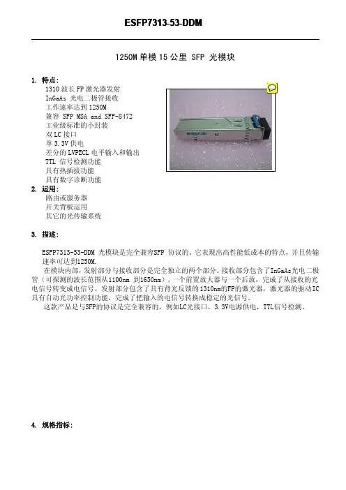
1250M单模15公里SFP光模块1.特点:1310波长FP激光器发射InGaAs光电二极管接收工作速率达到1250M兼容SFP MSA and SFF-8472工业级标准的小封装双LC接口单3.3V供电差分的LVPECL电平输入和输出TTL信号检测功能具有热插拔功能具有数字诊断功能2.运用:路由或服务器开关背板运用其它的光传输系统3.描述:ESFP7313-53-DDM光模块是完全兼容SFP协议的。
它表现出高性能低成本的特点,并且传输速率可达到1250M.在模块内部,发射部分与接收部分是完全独立的两个部分。
接收部分包含了InGaAs光电二极管(可探测的波长范围从1100nm到1650nm),一个前置放大器与一个后放,完成了从接收的光电信号转变成电信号。
发射部分包含了具有背光反馈的1310nm的FP的激光器,激光器的驱动IC 具有自动光功率控制功能,完成了把输入的电信号转换成稳定的光信号。
这款产品是与SFP的协议是完全兼容的,例如LC光接口,3.3V电源供电,TTL信号检测。
4.规格指标:极限工作指标参数参数符号最小值最大值单位存储温度Ts-40+85°C工作温度To0+75°C供电电压Vcc-0.5+3.7VESFP7313-53-DDM(1310nm FP and PIN,15km)发射部分光口,电口的参数Parameter Symbol Min.Typ.Max.Unit Note 差分的输入阻抗Rin100Ω发射差分的输入电压VinPP3001600mV发射失效电压高 2.0V发射失效电压低0.8V发射故障指示电压高 2.0V发射故障指标是压低0.8V发射失效插入时间0.145us发射光功率Po-9-3dBm消光比ER10dB中心波长λ1310nm输出光谱∆λ5nm接收部分电、光特性参数符号最小值典型值最大值单位注明差分的接收输出信号VoutPP4001600mV接收信号检测电压高2nm接收信号检测电压低0.8dBm接收灵敏度Sen-23dBm最大的输入光功率PinMAX-3dBm-信号检测范围-35-24dBm-信号检测滞后0.5dB-5.管脚定义:Notes:1.TX Fault:开集电极或者开漏集输出。
ddm光模块规格书DDM光模块规格书一、引言DDM光模块规格书是针对DDM光模块的技术规范和性能要求进行详细说明的文件。
本规格书旨在为用户提供关于DDM光模块的准确、全面的信息,帮助用户了解和正确使用该产品。
二、产品概述DDM光模块是一种光通信设备,用于光纤通信系统中的光信号传输。
它是一种具有数字诊断功能的光模块,能够实时监测和报告光模块的工作状态和性能参数。
DDM光模块主要用于数据中心、交换机、路由器等网络设备中,以提供可靠和高效的光纤传输。
三、技术规范1. 光学性能:- 工作波长范围:850nm,1310nm,1550nm- 光纤类型:多模光纤,单模光纤- 发射功率范围:-5dBm至-1dBm- 接收灵敏度范围:-20dBm至-3dBm- 光纤接口类型:LC/SC/FC/ST2. 电气性能:- 工作电压范围:3.3V- 传输速率范围:1Gbps,10Gbps,25Gbps,40Gbps,100Gbps- 接口类型:SFP/SFP+/QSFP/QSFP+/CFP- 工作温度范围:0℃至70℃3. DDM功能:- 工作温度监测- 工作电压监测- 工作电流监测- 发射功率监测- 接收功率监测- 模块故障报告四、性能要求1. 光学性能要求:- 发射功率稳定性:±0.5dB- 接收灵敏度稳定性:±1dB- 光纤传输距离:根据不同的波长和光纤类型,提供不同的传输距离选项2. 电气性能要求:- 工作电压稳定性:±5%- 传输速率误码率:低于10^-12- 工作温度范围要求:符合工业标准3. DDM功能要求:- 温度监测误差:±2℃- 电压监测误差:±0.1V- 电流监测误差:±2mA- 发射功率监测误差:±1dBm- 接收功率监测误差:±1dBm- 故障报告准确性:100%五、质量保证DDM光模块将严格按照国际质量管理体系进行生产和测试,以确保产品质量的稳定性和可靠性。
光模块的关键参数-概述说明以及解释1.引言1.1 概述概述部分的内容:光模块作为光通信系统中的关键组件,扮演着传输光信号的重要角色。
它将电信号转换为光信号,并在光纤之间进行传输。
光模块的性能和参数对于光通信系统的性能和稳定性具有至关重要的影响。
因此,了解光模块的关键参数是设计和优化光通信系统的关键步骤。
本文将详细介绍光模块的关键参数,以帮助读者更好地理解光模块的性能和工作原理。
在正文部分,我们将重点介绍三个关键参数,它们分别是关键参数1,关键参数2和关键参数3。
通过对这些参数的深入理解,读者将能够更好地评估光模块的性能,并选择适合自己需求的光模块。
在结论部分,我们将对这些关键参数进行总结,并分析它们对光模块性能的影响。
同时,我们也将探讨光模块未来的发展方向,以及可能的改进和创新方向。
通过本文的阅读,读者将对光模块的关键参数有更深入的了解,并能够更好地应用和优化光通信系统中的光模块。
1.2文章结构文章结构部分是为了帮助读者更好地理解整篇文章的组织和内容安排。
本文主要围绕光模块的关键参数展开,分为引言、正文和结论三个部分。
引言部分是文章的开篇,主要介绍本文的背景和目的。
概述部分简要说明了光模块的重要性及应用范围。
文章结构部分则提供了本篇长文的整体框架,让读者对文章内容有一个大致的了解。
目的部分明确说明了本文的目标,即通过解析光模块的关键参数,全面了解光模块的性能。
总结部分对本文进行了一次小结,概括了后续章节的内容和意义。
正文部分是本文的核心部分,分为三个章节,分别介绍了光模块的三个关键参数。
具体来说,关键参数1章节详细介绍了xxx参数的含义、重要性和测量方法。
关键参数2章节则着重探讨了xxx参数的特点、对光模块性能的影响以及常见的改进方法。
关键参数3章节则深入分析了xxx参数的实际应用场景和未来发展趋势。
结论部分是对整篇文章进行总结和回顾。
总结关键参数部分对前述章节的内容进行简要总结,概括出光模块关键参数的重要性和研究价值。
dwdm波长光模块的温度控制
DWDM(密集波分复用)波长光模块的温度控制是非常重要的,
因为温度的变化会影响光模块的性能和稳定性。
DWDM波长光模块通
常工作在特定的波长范围内,因此温度的变化可能会导致波长漂移,从而影响光信号的传输质量。
为了控制DWDM波长光模块的温度,通常会采用温度传感器和温
度控制器。
温度传感器用于监测光模块的温度变化,而温度控制器
则根据传感器的反馈信号来调节光模块周围的温度。
常见的温度控
制方法包括使用风扇进行散热,或者采用Peltier制冷器来维持恒
定的温度。
另外,一些DWDM波长光模块还可能具有温度补偿功能,即在光
模块内部对温度变化进行补偿,以保持输出光信号的稳定性。
这种
温度补偿通常通过内部的控制电路来实现,可以有效地减小温度变
化对光模块性能的影响。
总的来说,对于DWDM波长光模块的温度控制,关键是要保持光
模块工作在稳定的温度环境下,以确保其性能和传输质量。
通过合
理的温度监测和控制手段,可以有效地提高光模块的稳定性和可靠性,从而满足不同应用场景的需求。
光模块的一些常识光纤模块的构成:有发射激(TOSA),接受(ROSSA) 线路板 IC 外部配件光纤模块接口分为FC型、SC型、LC型、ST型和FTRJ型。
RJ45 光收发一体模块分类按照速率分:以太网应用的100Base(百兆)、1000Base(千兆)、10GE SDH应用的155M、622M、2.5G、10G按照封装分:1×9、SFF、SFP、GBIC SFP+ XFP X2 XENPAK1×9封装--焊接型光模块,一般速率有52M/155M/622M/1.25G,多采用SC接口SFF封装--焊接小封装光模块,一般速率有155M/622M/1.25G/2.25G/4.25G,多采用LC接口GBIC封装--热插拔千兆接口光模块,采用SC接口SFP封装--热插拔小封装模块,目前最高数率可达155M/622M/1.25G/2.125G/4.25G/8G/10G,多采用LC接口XENPAK封装--应用在万兆以太网,采用SC接口XFP封装--10G光模块,可用在万兆以太网,SONET等多种系统,多采用LC接口按照激光类型分:LED、VCSEL、FP LD、DFB LD按照发射波长分:850nm、1310nm、1550nm等等按照使用方式分:非热插拔(1×9、SFF),可热插拔(GBIC、SFP、XENPAK、XFP)光纤模块又分单模和多模单模光纤使用的光波长为1310nm或1550 nm。
单模光纤的尺寸为9-10/125μm 它的传输距离一般10KM 20kM 40KM 70KM 120KM多模光纤使用的光波长多为850 nm或1310nm.多模光纤50/125μm或62.5/125μm两种,它的传输距离也不一样,一般千兆环境下50/125μm线可传输550M,62.5/125μm只可以传送330M。
(2KM 550M)从颜色上可以区分单模光纤和多模光纤。
单模光纤外体为黄色,多模光纤外体为橘红色。
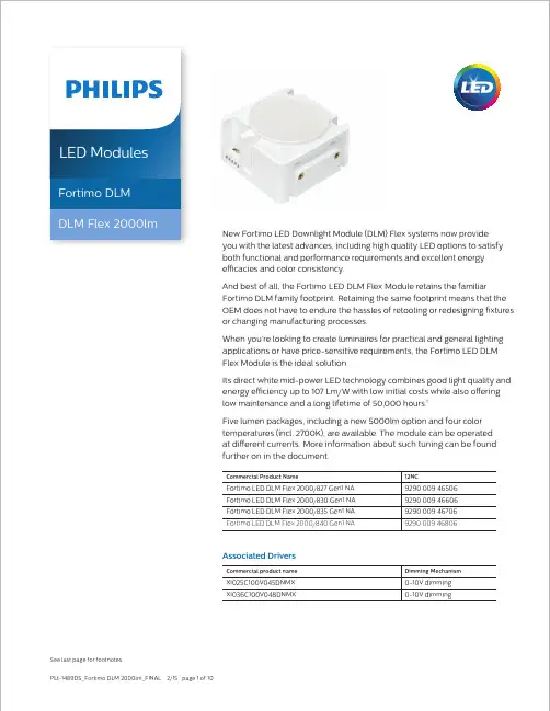
New Fortimo LED Downlight Module (DLM) Flex systems now provide you with the latest advances, including high quality LED options to satisfy both functional and performance requirements and excellent energy efficacies and color consistency.And best of all, the Fortimo LED DLM Flex Module retains the familiarFortimo DLM family footprint. Retaining the same footprint means that the OEM does not have to endure the hassles of retooling or redesigning fixtures or changing manufacturing processes.When you’re looking to create luminaires for practical and general lighting applications or have price-sensitive requirements, the Fortimo LED DLM Flex Module is the ideal solution.Its direct white mid-power LED technology combines good light quality and energy efficiency up to 107 Lm/W with low initial costs while also offering low maintenance and a long lifetime of 50,000 hours.Five lumen packages, including a new 5000lm option and four color temperatures (incl. 2700K), are available. The module can be operated at different currents. More information about such tuning can be found further on in the document.Commercial Product NameFortimo LED DLM Flex 2000/827 Gen1 NA Fortimo LED DLM Flex 2000/830 Gen1 NA Fortimo LED DLM Flex 2000/835 Gen1 NA Fortimo LED DLM Flex 2000/840 Gen1 NALED ModulesFortimo DLM DLM Flex 2000lmCommercial product nameXI025C100V045DNMX XI036C100V048DNMXAssociated DriversL.O.R.= 1.00Nominal Current (mA)680600580580Note: Specifications stated at Tc nom = 75°C70%75C 65CLumen Maintenance Nominal Conditions85C70%。
光模块的主要功能
光模块啊,这可是个挺有趣的小玩意儿呢。
光模块的功能之一就是实现光电转换。
你想啊,在我们这个到处都是数据“跑来跑去”的时代,电信号和光信号就像是两种不同语言的小伙伴。
电信号在我们的电子设备里欢快地蹦跶,可要是想在光纤里跑得更远更快,那就得变成光信号。
光模块就像是个神奇的翻译官,把电信号这个小调皮鬼变成光信号这个优雅的小天使,让数据能在光纤里愉快地旅行。
它还能保证数据传输的准确性。
就好比你寄包裹,要是包裹在途中被弄乱了或者丢了一些东西,那可就糟糕了。
光模块可不会让这种事情发生在数据身上。
它小心翼翼地护送着数据,就像一个超级负责的快递员,确保每一个数据小包裹都能完整无损地到达目的地。
光模块还有个很棒的功能,就是适应不同的传输距离。
不管是短距离的小溜达,像是在一个小机房里的数据传输,还是长距离的长途跋涉,比如城市与城市之间的数据通信,光模块都能轻松应对。
就像一个万能的小助手,不管是近路还是远路,都能稳稳地把事情办好。
另外呀,光模块还能支持不同的传输速率。
现在的网络速度那是越来越快啦,什么百兆、千兆甚至万兆的。
光模块就像个灵活的小超人,不管是多快的速度要求,它都能跟着节奏来,一点也不含糊。
它能很好地配合各种设备,让设备之间的交流就像好朋友聊天一样顺畅,不会因为速度不匹配而出现卡顿或者混乱的情况。
光模块在整个网络通信里就像一颗小小的、但是超级重要的螺
丝钉。
缺了它,网络这个大机器可就运转得没那么顺畅啦。
6G S F P + T r a n s c e i v e r M T R S -6E 31-01DescriptionMTRS-6E31-01 is a high performance, cost effective modules, which is supporting Multi Rate 1.25-8.6Gbps, and transmission distance up to 10km on SM fiber. The transceiver consists of two sections: The transmitter section incorporates a 1310nm DFB driver and re-timer. The receiver section consists of a PIN photodiode integrated with a transimpedance preamplifier (TIA). The module is hot pluggable into the 20-pin connector. The high-speed electrical interface is base on low voltage logic, with nominal 100 Ohms differential impedance and AC coupled in the module.The optical output can be disabled by LVTTL logic high-level input of TX_DIS. Transmit Fault (Tx_Fault) is provided to indicate that the module transmitter has detected a fault condition related to laser operation or safety. Loss of signal (RX_LOS) output is provided to indicate the loss of an input optical signal of receiver. A serial EEPROM in the transceiver allows the user to access transceiver monitoring and configuration data via the 2-wire SFP Management Interface. This interface uses a single address, A0h, with a memory map divided into a lower and upper area. Basic digital diagnostic (DD) data is held in the lower area while specific data is held in a series of tables in the high memory area.Features● Up to 10KM transmission distance ● Support Multi Rate 1.25-8.6Gbps ●1310nm DFB and PIN receiver ●SFI electrical interface● 2-wire interface for integrated Digital Diagnostic monitoring ● SFP+ MSA package with duplex LC connector ● Hot pluggable ● Very low EMI and excellent ESD protection ● +3.3V power supply ● Power consumption less than 1W ● Operating case temperature: -40~+85°C Applications ● High-speed storage area networks ● Computer cluster cross-connect ● Custom high-speed data pipes ● LTE optical repeater application Compliance ● Compliant with Fiber Channel(FC)-Standard INCITS 352 ●Compliant with IEEE 802.3ae-2002● Compliant with FCC 47 CFR Part 15, Class B ● Compliant with FDA 21 CFR 1040.10 and 1040.11, Class I except for deviations pursuantSpecificationAbsolute Maximum RatingsUnit Storage Temperature T S-40 +85 ℃Supply Voltage V CC3 0 3.6 V Relative Humidity RH 5 +95 %RX Input Average Power Pmax - 3 dBmRecommended Operating ConditionsMax. Unit Operating Case Temperature T C-40 25 +85 ℃VV CC3 3.13 3.3 3.47Power Supply VoltageI CC3300 mAPower Dissipation P D 1 WData Rate 8.6 Gbps Transmission Distance 10 Km Transmitter Operating Characteristic-Optical, ElectricalUnit NoteSpectral Width(-20dB)Pm - - 1 nmSide Mode Suppression Ratio SMSR 35 - dBmLaser Off Power Poff - - -30 dBmExtinction Ratio ER 3.5 - - dBTransmitter Dispersion Penalty TDP - - 3.2 dBRelative Intensity Noise Rin - - -128 dB/HzOptical Return Loss Tolerance 12 - - dBOperating Data Rate 8.6 GbpsCentre Wavelength λC1260 1310 1355 nm Note1Average Optical Power Pavg -8.2 - 0.5 dBm Note1Optical Eye Mask Compliant with IEEE 802.3ae Note2Single Ended Output Voltage Tolerance -0.3 4 VCommon mode voltage tolerance 15 - mVTx Input Diff Voltage VI 180 700 mVTx Fault VoL -0.3 0.4 V At 0.7mAData Dependent Input Jitter DDJ 0.1 UIData Input Total Jitter TJ 0.28 UINotes:[1] Average optical power shall be measured using the methods specified in TIA/EIA-455-95.[2] Vertical eye closure penalty and stressed eye jitter are the test conditions for measuring stressed receiversensitivity. They are not the required characteristic of the receiver.Receiver Operating Characteristic-Optical, ElectricalUnit Note Center Wavelength λr 1260 1310 1360 nmReceiver Sensitivity (OMA) Psens -14.4 dBmStressed Sensitivity (OMA) -12.6 dBmLos Assert LosA -30 - dBmLos Dessert LosD -16 dBmLos Hysteresis LosH 0.5 - dBOverload Pin 0.5 dBmStressed Eye Jitter 0.3 UIp-p Note1 Receive electrical 3dB upper cutoff frequency12.3 GHzVertical Eye Closure Penalty 2.2 dB Note2 Receiver Reflectance -12 dBOperating Data Rate 8.6 GbpsSingle Ended Output Voltage Tolerance -0.3 4 VRx Output Diff Voltage Vo 450 850 mVRx Output Rise and Fall Time Tr/Tf 30 ps 20% to 80% Total Jitter TJ 0.7 UIDeterministic Jitter DJ 0.42 UINotes:[1] Receiver sensitivity is informative. Stressed receiver sensitivity shall be measured with conformance test signalfor BER =1x 10-12 .[2] Vertical eye closure penalty and stressed eye jitter are the test conditions for measuring stressed receiversensitivity. They are not the required characteristic of the receiver.Control and Status I/O Timing CharacteristicsNoteTX Disable Assert Time t_off 10 µs Note1TX Disable Negate Time t_on 1 ms Note2 Time to initialize including reset of TX_Fault t_init 300 ms Note3TX Fault Assert Time t_fault 100 µs Note4TX Disable to reset t_reset 10 µs Note5LOS Assert Time t_loss_on 100 µs Note6LOS Deassert Time t_loss_off 100 µs Note7Rate-Select Change Time t_ratesel 10 µs Note8 Serial ID Clock Rate f_serial_clock100 kHzNotes:[1] Time from rising edge of TX Disable to when the optical output falls below 10% of nominal[2] Time from falling edge of TX Disable to when the modulated optical output rises above 90% of nominal[3] From power on or negation of TX Fault using TX Disable[4] Time from fault to TX fault on[5] Time TX Disable must be held high to reset TX_fault[6] Time from LOS state to RX LOS assert[7] Time from non-LOS state to RX LOS deassert.[8] Time from rising or falling edge of Rate Select input until receiver bandwidth is in conformance with appropriatespecificationOptical Characteristics(Multi Rate Characteristics)4.95GTotal Power Consumption<1W <1W <1WTx Light Output Power >-8.2 >-8.2 >-8.2Extinction Ratio >3.5 >3.5 >3.5Eye Mask Margin >20% >20% >20%Rx Sensitivity <-22.0dBm <-20.0dBm <-17.0dBm-40~+85C -40~+85C -40~+85C WorkingTemperatureNotes:[1] For 1.25G data rate, the modules performance is compatible with 1G FC application but not fully compliant. If customer needs to fully compliant with 1.25G data rate specifications, we need to implement “Rate-Selection” function, please contact our sales team for detailed information.Pin-out DefinitionFigure1Pin AssignmentNote 1VeeT Module Transmitter Ground Note12 LVTTL-O TX_Fault Module Transmitter Fault Note23 LVTTL-I TX_Disable Transmitter Disable; Turns off transmitter laser output Note34 LVTTL-I/O SDA2-wire Serial Interface Data Line (Same as MOD-DEF2 as definedNote4in the INF-8074i)5 LVTTL-I/O SCL2-wire Serial Interface Clock (Same as MOD-DEF1 as defined inNote4the INF-8074i)6 MOD_ABS Module Absent, connected to VeeT or VeeR in the module Note57 LVTTL-I RS0Not used8 LVTTL-O RX_LOS Receiver Loss of Signal Indication (In FC designated as RX_LOS,in SONET designated as LOS, and in Ethernet designated at SignalNote2Detect)9 LVTTL-I RS1Not used10 VeeR Module Receiver Ground Note111 VeeR Module Receiver Ground Note112 CML-O RD-Receiver Inverted Data Output13 CML-O RD+Receiver Non-Inverted Data Output14 VeeR Module Receiver Ground Note115 VccR Module Receiver 3.3 V Supply16 VccT Module Transmitter 3.3 V Supply17 VeeT Module Transmitter Ground Note118 CML-I TD+Transmitter Non-Inverted Data Input19 CML-I TD-Transmitter Inverted Data Input20 VeeT Module Transmitter Ground Note1 Notes:[1] The module signal ground pins, VeeR and VeeT, shall be isolated from the module case.[2] This pin is an open collector/drain output pin and shall be pulled up with 4.7k-10kohms to Host_Vcc on the hostboard. Pull ups can be connected to multiple power supplies, however the host board design shall ensure that no module pin has voltage exceeding module VccT/R + 0.5 V.[3] This pin is an open collector/drain input pin and shall be pulled up with 4.7k-10kohms to VccT in the module.[4] See sff-8431 4.2 2-wire Electrical Specifications .[5] This pin shall be pulled up with 4.7k-10kohms to Host_Vcc on the host board.Block Diagram of TransceiverFigure2Transmitter SectionThe transmitter converts 6.25Gbit/s serial PECL or CML electrical data into serial optical data compliant with the6GBASE-LR standard. An open collector compatible Transmit Disable (Tx_Dis) is provided. A logic “1,” or no connection on this pin will disable the laser from transmitting. A logic “0” on this pin provides normal operation. The transmitter has an internal automatic power control loop (APC) to ensure constant optical power output across supply voltage and temperature variations. An open collector compatible Transmit Fault (Tx_Fault) is provided.TX_Fault is a module output contact that when high, indicates that the module transmitter has detected a fault condition related to laser operation or safety. The TX_Fault output contact is an open drain/collector and shall be pulled up to the Vcc_Host in the host with a resistor in the range 4.7-10 kΩ. TX_Disable is a module input contact. When TX_Disable is asserted high or left open, the SFP+ module transmitter output shall be turned off. This contact shall be pulled up to VccT with a 4.7 kΩ to 10 kΩ resistorReceiver SectionThe receiver converts 10Gbit/s serial optical data into serial PECL/CML electrical data. An open collector compatible Loss of Signal is provided. Rx_LOS when high indicates an optical signal level below that specified in the relevant standard. The Rx_LOS contact is an open drain/collector output and shall be pulled up to Vcc_Host in the host with a resistor in the range 4.7-10 kΩ, or with an active termination. Power supply filtering is recommended for both the transmitter and receiver. The Rx_LOS signal is intended as a preliminary indication to the system in which the SFP+ is installed that the received signal strength is below the specified range. Such an indication typically points to non-installed cables, broken cables, or a disabled, failing or a powered off transmitter at the far end of the cable.Recommended Interface CircuitFigure3DimensionsFigure4Table 1: Key Mechanical DimensionsDigital Diagnostic Memory MapEEPROM InformationName of Field Hex Description0 1 Identifer 03 SFP1 1 Ext. Identifier 04 SFP function is defined by serial ID only2 1 Connector 07 LC Connector 3-10 8 Transceiver 00 Transceiver Codes11 1 Encoding 06 64B/66B 12 1 BR, Nominal 3F 6250Mb/s 13 1 Rate Identifier 00 Unspecified14 1 Length (9um) km 0A Transceiver transmit distance,10km 15 1 Length (9um) 100m 64 Transceiver transmit distance,10km 16 1 Length (50um)10m 00 Transceiver transmit distance 17 1 Length (62.5um) 10m 00 Transceiver transmit distance18 1 Length (Copper) 00 Not compliant 19 1 Length (50um OM3) 00Not compliant20-35 16 Vendor name 48 47 20 47 45 4E 55 49 4E 45 20 20 20 20 20 20“HG GENUINE” Vendor Name(ASCII)36 1 Reserved 00 37-39 3 Vendor OUI 00 00 0040-55 16 Vendor PN 4D 54 52 53 2D 36 45 3331 2D 30 31 20 20 20 20“M T R S -6E 31-01”P a r t N o .(ASCII)56-59 4 Vendor rev 31 2E 30 20 “1.0” (ASCII) 60-61 2 Wavelength 05 1E Transceiver wavelength621Reserved0063 1 CC_BASE AD Check code for Base ID Fields64-65 2 Options 001A TX_DISABLE, TX_FAULT and Loss of Signal implemented.66 1 BR,MAX 00 Not Specified67 1 BR,MIN 00 NotSpecified 68-83 16 Vendor SN SN(Variable) Serial Number of transceiver(ASCII). 84-91 8 Date code DC(Variable) Manufactory Date Code.92 1 Diagnostic MonitoringType68Digital diagnostic monitoringimplemented, “externally calibrated”is implemented93 1 EnhancedOptions F0Optional Alarm/Warning flagsimplemented for all monitored quantities, Optional Soft TX_Disable control and monitoring implemented, Optional Soft TX_FAULT monitoring implemented, Optional Soft RX_LOS monitoring implemented94 1SFF_8472Compliance01Includes functionality described inRev9.3 SFF-847295 1 CC_EXT CS(Variable) Check sum for Extended ID Field.96-127 32 Vendor Specific Read only Depends on customer informationFilled by zero128-255 128 Reserved Read only Filled by zeroOrdering InformationReach Others MTRS-6E31-01SFP+6G1310nm DFB-8.2—0.5dBm PIN<-14.4dBm -40~85℃10km DDM/RoHSRelated Product InformationMTRS-1E21-01SFP+10G1310nm FP-8.2—0.5dBm PIN<-14.4dBm-40~85℃2km DDM/RoHS MTRS-02X13-G SFP+10G1310nm DFB-8.2—0.5dBm PIN<-14.4dBm0~70℃10km DDM/RoHS MTRS-1E31-01SFP+10G1310nm DFB-8.2—0.5dBm PIN<-14.4dBm-40~85℃10km DDM/RoHS MTRS-1E20-01SFP+10G1310nm FP-8.2—0.5dBm PIN<-14.4dBm0~70℃2km DDM/RoHS MTRS-6E21-01SFP+6G1310nm FP-8.2—0.5dBm PIN<-14.4dBm-40~85℃2km DDM/RoHS MTRS-6E20-01SFP+6G1310nm FP-8.2—0.5dBm PIN<-14.4dBm0~70℃2km DDM/RoHS MTRS-6E30-01SFP+6G1310nm DFB-8.2—0.5dBm PIN<-14.4dBm0~70℃10km DDM/RoHSWuhan Huagong Genuine Optics Technology Co., LtdAddress: Science & Technology Region of HUST, Donghu High-Tech ZoneWuhan, Hubei Province, 430223, China●Tel: +86-27-87180102●Fax: +86-27-87180220Email: market@Website: StatementHG Genuine possesses the authority for ultimate explanation of all information contained in this document, which is subject to change without prior notice. All the information was obtained in specific environments; and HG Genuine will not be responsible for verifying the products performance in customers’ operating environments, neither liable for the performance of users' products. All information contained is only for the users' reference and shall not be considered as warranted characteristics. HG Genuine will not be liable for damages arising directly or indirectly from any use of the information contained in this document.Publishing Date: 2010-01-08Copyright HG GenuineAll Right Reserved。
光模块 ddmi 温度光模块DDMI温度光模块是一种用于光通信的设备,它在传输光信号的过程中会产生一定的热量。
而DDMI(Digital Diagnostic Monitoring Interface)则是一种监测光模块工作状态的接口。
其中,温度是DDMI接口中的一个重要参数,对光模块的工作性能和寿命都有一定的影响。
光模块的温度是指其工作时的温度,通常以摄氏度(℃)为单位。
光模块在工作时会发热,因此需要监测其温度,以确保其正常工作。
过高的温度可能会导致光模块性能下降甚至损坏,因此温度监测对于光模块的可靠性和稳定性非常重要。
DDMI接口可以通过读取光模块内部的温度传感器来获取光模块的温度信息。
温度传感器通常位于光模块的芯片中,通过测量芯片的温度来确定光模块的工作温度。
由于光模块的工作温度通常较高,所以温度传感器需要具备较高的精度和稳定性。
光模块DDMI温度的监测和管理是非常重要的,可以通过温度传感器实时监测光模块的温度,并将温度值传输给系统,以便进行进一步的分析和处理。
通过监测光模块的温度,可以及时发现温度异常或过高的情况,并采取相应的措施,以保证光模块的正常工作和长期稳定性。
在光通信系统中,光模块的温度管理也是一个重要的问题。
由于光模块通常安装在机架或设备中,周围环境的温度可能会对光模块的工作温度产生影响。
因此,在设计光通信系统时,需要考虑光模块的散热和温度管理,以确保光模块在适宜的温度范围内工作。
为了保证光模块的正常工作,可以采取一些措施来控制温度。
例如,可以合理设计光模块的散热结构,增加散热面积,提高散热效率。
同时,可以通过空调或风扇等设备来控制光模块周围环境的温度,以确保光模块工作在适宜的温度范围内。
在实际应用中,光模块DDMI温度的监测和管理是不可或缺的。
通过监测光模块的温度,可以及时发现温度异常,防止光模块的过热或过冷导致的故障。
同时,合理的温度管理可以延长光模块的使用寿命,提高光通信系统的可靠性和稳定性。