征服者电子狗网站升级
- 格式:doc
- 大小:261.50 KB
- 文档页数:1
任我游GoU车载导航仪地图升级操作说明文件说明:将您下载的地图压缩包完全解压之后,获得“任我游GoU系列机器新版地图更新”文件夹,该文件夹中包括如下四个文件:●任我游GoU系列自动更新补丁:用于更新低版本(具体版本参照下文说明)软件机型的软件升级●任我游GoU系列软件文件:任我游GoU系列机器最新V2.2.6版本软件●任我游GoU系列地图文件:任我游GoU系列机器最新V2.1.0(2010年夏)版本地图文件●任我游GoU系列更新说明:任我游GoU系列机器软件及地图更新操作说明文档任我游GoU系列机器新版地图更新步骤说明一、软件更新升级一)软件更新补丁安装●特别提示:1、请您在更新操作前务必核实您机器目前的软件版本,如果低于1.2.5(不含),请继续进行软件更新补丁安装的操作。
如果您机器的软件本版已经为 1.2.5(含)及以上版本,则无需进行更新补丁的操作,直接进入下一步“软件版本升级”即可◆软件版本查看方法:1、将您的导航仪开机后,点选屏幕中的“工具”选项,然后点选“设置”---“系统”---“关于”,进入关于界面后即可看到您导航仪软件版本2、请在进行以下操作前务必确定您的导航仪电量充足3、进行升级软件更新补丁的操作,请您务必自行准备一张空白SD卡(SD卡大小不小于256MB即可)●使用SD卡升级软件更新补丁本步骤仅针对1.2.5版本以下的软件版本机器适用1、打开任我游GoU系列机器新版地图更新文件夹中的“任我游GoU系列自动更新补丁”2、在“任我游自动更新补丁”文件夹中包括两个文件,分别为:“APP”文件夹以及“UPDATE.CFG”3、将两个文件“APP”文件夹和“UPDATE.CFG”文件拷贝到准备好的空白SD卡中;4、文件拷贝完毕,将SD卡插入任我游导航仪中,然后将导航仪开机;5、导航仪开机后,会自动进入文件读取过程。
此时,请您耐心等待,文件读取传输完毕后机器屏幕会自动弹出“Please remove update SD card”的提示框;6、待传输完毕的提示框出现之后,请务必先将插入导航仪的SD卡取出,然后点击导航仪屏幕提示框中的“OK”按钮,机器自动重启;7、待机器再次重新启动完成后,自动升级补丁步骤即完成。

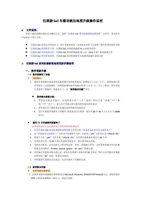
1.打开Internet explorer浏览器,在网址栏里输入地址并按回车。
(说明书后有,照下图输入也可)
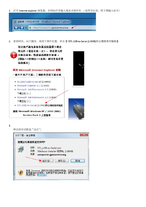
2.看到网页,向下翻页,找到下图中位置,单击【•DTL USB-to-Serial (2.0MB)特定機種專用驅動】。
3.
弹出的对话框选“运行”,
4.下载完成后自动弹出安装程序框(如遇到“是否安装”等字样一律选“是、安装”之类选项。
)
5.根据提示选下一步、下一步、安装、完成。
安装完成后关机并重启。
6.再次开机后先把数据线连在电脑上。
按照第一步打开网页,向下翻页,找到下图所示内容并单击图片。
选“确定”。
7.弹出更新服务对话框,选“北方网通”,选“更新”。
8.更新期间电子狗屏幕上显示的数字为完成的百分比。
大概需要等待15分钟左右。
等待自动更新完成,电子狗
发出声音,更新程序下框中显示“更新完成”即可拔下插头使用。
豪捷行车记录仪E8数据升级步骤
我们将竭诚为您服务
行车记录仪三合一领导者
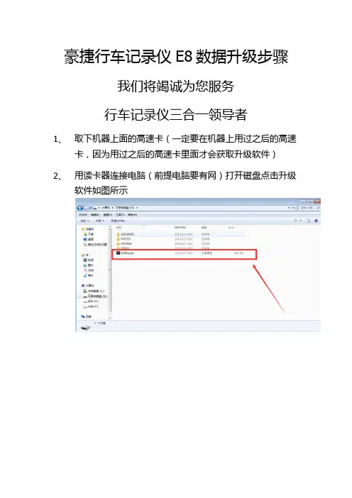
1、取下机器上面的高速卡(一定要在机器上用过之后的高速
卡,因为用过之后的高速卡里面才会获取升级软件)
2、用读卡器连接电脑(前提电脑要有网)打开磁盘点击升级
软件如图所示
3、弹出系统升级提示点击是
4、等待更新
5、下载到61%时肯能会出现以下情况,属于正常,只要等
待即可
6、等待1分钟左右弹出下载成功窗口
7、打开磁盘,可以看见以下下载成功的程序
8、将内存卡插到机器上面,然后务必连接车充开机,因为升
级需要3-5分钟左右,需保证机器电量充足。
9、开机后,一次呈现以下三个界面,之后屏幕熄灭即升级完
成,此过程需要3-5分钟,请耐心等待!。
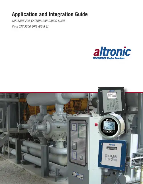
Application and Integration Guide UPGRADE FOR CATERPILLAR G3500 SI/EISForm CAT-3500-UPG AIG 8-111.0 SYSTEM DESCRIPTION1.1 The retrofit ignition/control system for Caterpillar G3500 SI/EIS is a simple, pre-engineered solution that allows operators of legacy G3500 engines equipped with SI or EIS ignition systems an upgrade path to industry-standard, cost-effectiveAltronic ignition and control components. This package enables operators of these engines to enjoy greater flexibility in the control of their equipment, and ensures future parts availability and upgrade options through Altronic and it’s globalDistributor network. The key components of this upgrade include the CPU-95ignition, the DET-1600 detonation detection system, and the DSG-1682DUPSdual-setpoint gauge.1.2 The Altronic CPU-95, DC-powered ignition system is a microprocessor-basedcapacitor discharge system designed for application on natural gas fueled engines.The system features crankshaft-triggered timing accuracy and the capability tovary timing electronically by several means, including an external 4-20mA control signal. The system is field-programmable and offers a variety of advanced control methods, primary and spark diagnostics, self-diagnostics, serial communications and engine protection features. The system consists of two main parts: an engine-mounted Ignition Module and a user interface Display Module.1.3 The Altronic DET-1600 Detonation Sensing Monitor is a 32-bit microprocessor-based electronic instrument that detects and eliminates detonation on naturalgas-fueled engines before damage occurs. Industry-standard low cost broadband piezoelectric vibration sensors, mounted on the engine, are used to transform the vibrations caused by detonation into electrical signals which are then evaluated by the DET-1600. The Detonation Sensing Monitor uses the sensors to measure the combustion intensity of each cylinder in a user-configured time window.The detonation signals are filtered by programmable filters and then sent to the microprocessor for further processing and evaluation. This process is repeatedfor every cylinder on a cycle-by-cycle basis. The resulting two reference numbers, one for detonation intensity and the other for the lack of a combustion process, or misfire, are displayed on a LCD display. These reference numbers are usedto control two output switches, typically one for load control and the other forshutdown, and a 4-20mA current loop used to retard ignition timing.1.4 The Altronic DSG-1682DUPS Digital Bargraph Setpoint Gauge is a two-channelelectronic instrument used to measure two variables and to output a 4-20mAsignal proportional to the differential. Although the gauge is intended to measure pressure, temperature, or vibration, virtually any signal in the range of 0-5V, 0.5-4.5V, or 0-20mA can be used. A backlit, 128 x 64 graphic LCD screen displaysnumeric values, engineering units, labels, and the state of the outputs. A front-mount membrane keypad serves as the user interface.2.0 OVERVIEW AND THEORY OF OPERATION2.1 The retrofit ignition and control system for the Caterpillar G3500 SI/EIS equippedengines allows for the G3500 engine to operate with standard Altronic ignition and control equipment, giving the user the ability to adjust engine operating parameters as the application requires. The system monitors key parameters of engineoperation and adjusts the ignition timing according to a multi-point, user-defined map of ignition timing values. These points include:n I gnition Timing vs. Engine Speedn I gnition Timing vs. Air Manifold Pressuren I gnition Timing vs. Engine Detonation2.2 The ignition timing vs. engine speed curve is a piece-wise linear function that isprogrammed into the CPU-95 output module. This function calculates the global ignition timing retard based on the current engine speed. This function forms one-half of the basic, open-loop ignition timing map used in the G3500 retrofit system.2.3 The ignition timing vs. air manifold pressure curve is a linear function that isprogrammed into the CPU-95 and DSG-1682DUPS gauges. For most commonapplications it is assumed that the air manifold pressure is closely tied to theengine power output, making it a good indication of load. This relationship is based on the premise that higher air manifold pressure results in a larger mass of air and fuel in the combustion chamber. This function forms the other half of the basic, open-loop ignition timing map used in the G3500 retrofit system.2.4 The ignition timing vs. engine detonation curve is a linear function that isprogrammed into the DSG-1682DUPS gauge. It is implemented as an offset to the air manifold pressure curve, allowing for varying amounts of detonation-based ignition timing authority, depending on the particular application. The detonation function is essentially a closed-loop feedback from the engine to adjust the ignition timing based on current combustion characteristics. The DET-1600 is capableof taking additional action in the case of engine detonation using onboard output switches—this may include load control and ultimately, shutdown, depending on the needs of the application.3.0 COMPONENTS3.1 CPU-95 Output Module – See forms CPU-95 AL, CPU-95 II, CPU-95 OI, CPU-95 PI, and CPU-95 SI for complete explanation.3.2 CPU-95 Display Module – See forms CPU-95 AL, CPU-95 II, CPU-95 OI-ED, andfor complete explanation.3.3 Ignition to Junction-box Harness – Dual-connector, shielded, liquid-tite wiringharness that connects from the CPU-95 output module to the ignition junctionbox. Length of this harness should be kept to minimum required for on-engineinstallation. See form EZRail II for additional information.3.4 Ignition Junction-box – EZRail-style, sealed and potted ignition junction-box intendedto mount on-engine and route ignition firing events to the appropriate enginecylinders. Good installation practices dictate that the junction box be mounted as close to the CPU-95 output module as possible. This box should be mounted at the fly-wheel end of the G3500 engine. Choose the appropriate number of outputs for your engine configuration. See form EZRail II for additional information.3.5 Ignition Primary Harness – On-engine wiring harness that connects the ignitionjunction box to the ignition coils. This harness is constructed from PLTC-ER-rated cable, making it suitable for use in hazardous areas—provided the applicableelectrical codes are followed. Each engine bank requires one harness; select the harness with the appropriate number of outputs for your application.3.6 Magnetic Pickups – The CPU-95 ignition uses two magnetic pickups to determineposition information used in calculating ignition timing. See forms CPU-95 AL and CPU-95 II for additional documentation.3.7 Cycle Trigger – The CPU-95 ignition uses a cycle trigger system to determineposition information used in calculating ignition timing. See forms CPU-95 AL and CPU-95 II for additional documentation.3.8 Flange Ignition Coil – The flange-style ignition coil is used in conjunction withthe mating Caterpillar flange-coil valve cover to deliver high-voltage ignitionpulses to the sparkplugs. The standard-duration 591018 coil is specified for new installations, but the long-duration 591012 coil can be used when required.3.9 DET-1600 Detonation Detection System – See form DET-1600 IOM for completeexplanation.3.10 #1 Cylinder and “G” Lead Cable – Used to obtain #1 cylinder primary and ignition“G” lead from the ignition junction box as required by the DET-1600. Additional components may be required to route these signals to the DET-1600.3.11 DET-1600 Sensor Harness – On-engine wiring harness that connects theenclosure containing the DET-1600 to the engine detonation sensors. This harness terminates in a standard MS-5015-style 19-pin connector. An appropriate, panel-mount mate to this connector can be included in an enclosure built by AltronicControls or sourced separately. Each engine bank requires one harness; select the harness with the appropriate number of inputs for your application.3.12 DSG-1682DUPS Gauge – See form DSG-1682DUPS II for complete explanation.3.13 Additional OEM Components for EIS – Given the mechanical design of the EISignition system, additional OEM components are required to allow the engine to accept standard ignition coils and secondary systems. Altronic does not provide these components. The simplified list below should be used as reference only.Always consult the appropriate engine documentation to determine the exactconfiguration and quantity required.4.0 Application Example4.1 Ignition Timing vs. Engine Speed – For this example, it is assumed that theappropriate Ignition Timing vs. Engine Speed function has been defined as show in Figure 1.1. From this it can be determined that the most advanced ignition timing value desired is 28° before top dead center (BTDC) – thus 28° BTDC equals 0° of ignition retard (RET). Continuing this process of extrapolating the desired ignition timing vs. engine speed breakpoints it is possible to express the desired ignition timing in terms of °RET. This process generates the graph shown in Figure 1.2.Once the function is expressed in terms of °RET it is possible to program thisbehavior into the CPU-95 using the “RPM Map” function of the terminal program – see Figure 1.3.CAUTION: This section of the manualis intended to explain the method ofconfiguring the various ignition timingcontrols in the Caterpillar G3500retrofit system. The values used in thefollowing application example ARE INNO WAY REPRESENTATIVE OF ACTUALVALUES USED IN A FUNCTIONINGSYSTEM, and are only intended to helpthe reader understand how the systemcomponents interact. Always referto appropriate engine documentationand ensure that only qualifiedpersonnel establish appropriateignition timing values.FIG. 1.34.2 Ignition Timing vs. Air Manifold Pressure – For this example it is assumed that theappropriate Ignition Timing vs. Air Manifold Pressure function has been defined as show in Figure 2.1. The previous example established that the most advanced ignition timing value desired is 28° BTDC. Again, it is required to re-format the desired ignition timing in terms of °RET. As in the previous example, this process generates the graph shown in Figure 2.2.Given the air manifold pressure is measured in engineering units (i.e., PSIA, PSIG, bar) and the CPU-95’s 4-20mA input map is entered in terms of degreed and milliamps it is important to establish the conversion factor from engineering units to mA. Below is a mathematical process for calculating the formula for the engineering units to mA—assuming the standard Altronic 691204-50 pressure transducer is used and the DSG-1682DUPS is configured for that device the following holds true:CONVERSION FACTOR: 20mA – 4mA = 0.32mA50PSIA – 0PSIA PSIA CONVERSION OFFSET:20mA – (0.32 mA× 50PSIA ) = 4mA PSIACONVERSION FORMULA:CONV. FACTOR × ACTUAL PSIA + CONV. OFFSET = OUTPUT mA EXAMPLE:0.32 mA × 4PSIA + 4mA = 5.28mA PSIACAUTION: This section of the manual is intended to explain the method of configuring the various ignition timing controls in the Caterpillar G3500retrofit system. The values used in the following application example ARE IN NO WAY REPRESENTATIVE OF ACTUAL VALUES USED IN A FUNCTIONINGSYSTEM, and are only intended to help the reader understand how the system components interact. Always refer to appropriate engine documentation and ensure that only qualified personnel establish appropriate ignition timing values.For the values of air manifold pressure given in Figure 2.2, the following table showsthe equivalent points converted to work in the mA scale of the CPU-95.mA of current is complete it is possible to program this behavior into the CPU-95 using the “Special Current Loop Retard” function of the CPU-95 terminalprogram – see Figure 2.3.FIG. 2.34.3 Ignition Timing vs. Engine Detonation – The 4-20mA signal from the DET-1600controls ignition timing in the presence of detonation. This system implements the control as an offset value to the air manifold pressure in the DSG-1682DUPS. The relative impact of the DET-1600’s indicated detonation on ignition timing can becontrolled via the scale factor used in the DSG-1682DUPS—the larger the scale of “DETs”, the larger the overall impact on ignition timing will result. For example, if the DET-1600 input is scaled such that the DSG-1682DUPS interprets the input as 0-5 “DETs” the maximum effect of detonation is to offset the air manifold pressure function by 5. For the purposes of example, assume that the detonation input to DSG-1682DUPS is scaled such that it reads 0-5 “DETs”.4.4 Example:Engine Speed = 1350 RPMAir Manifold Pressure = 23PSIADetonation = 1.5 “DETs”Offset Air Manifold Pressure (0AMP) = 23PSIA – 1.5 “DETs” = 21.5 OAMPTiming = 28° BTDC – 0° RET (RPM) – 3.25° RET (OAMP) = 24.75° BTDCAPPLICATION DIAGRAMDET-1600 SENSOR HARNESS DIAGRAMIGNITION PRIMARY HARNESS DIAGRAM。
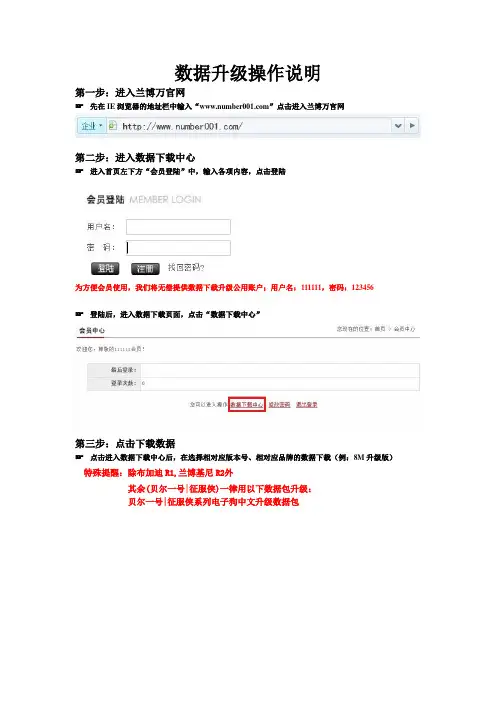
数据升级操作说明
第一步:进入兰博万官网
☞先在IE浏览器的地址栏中输入“”点击进入兰博万官网
第二步:进入数据下载中心
☞进入首页左下方“会员登陆”中,输入各项内容,点击登陆
为方便会员使用,我们将无偿提供数据下载升级公用账户;用户名:111111,密码:123456
☞登陆后,进入数据下载页面,点击“数据下载中心”
第三步:点击下载数据
☞点击进入数据下载中心后,在选择相对应版本号、相对应品牌的数据下载(例:8M升级版)特殊提醒:除布加迪R1,兰博基尼R2外
其余(贝尔一号|征服侠)一律用以下数据包升级:
贝尔一号|征服侠系列电子狗中文升级数据包
第四步:一键更新
☞把机器与电脑相连
特殊提醒:当机器与电脑连接成功时,机器显示OL字母,则可进行升级!☞当机器与电脑连接成功,解压您所下载的数据包,点击"EXE"文件开始一件升级
☞请点击“下一步”
☞按页面提示:请确认设备与电脑连接好,然后点击“开始”
☞按数据更新中,请耐心等待
☞按页面提示升级完毕,点击“完成”即可完成数据升级。
电子狗十大品牌排行榜第一名:凌速东莞市凌速电子科技有限公司,简称凌速电子、凌速,公司成立于2000年3月,涉及产业有GPS导航设备、汽车安全行驶语音提示器及汽车内外装饰系列产品等汽车电子用品领域,集科研、生产、销售于一体的公司。
2000年3月公司成立于广东东莞市2008年8月起,成立了国际市场事业部,正式与国外如美国、德国、法国、澳洲、新西兰、马来西亚、泰国等各国建立合作关系,并取得了美国FCC、欧盟的CE等国际认证;2009年,经国家核准注册经国家核准注册过『凌速』、『凌速卫星眼』商标,同年确定公司的英文名缩写为:LNSU ;2010年公司引进美式SG-3技术,推出美式微感袖珍一体机系列;2011年,引进韩版SWF-105/106广角式芯片技术,研发了出KG版系列机型;第二名:征服者台湾瑞忆科技2011年6月12日以公司本名,“厦门瑞忆科技有限公司”在厦门正式挂牌成立。
原大陆子公司东太利(厦门)电子有限公司不变,仍为瑞忆集团所投资产业之一。
台湾瑞忆集团成立于 1996 年,位于宝岛台湾的嘉义县。
主要研发及生产GPS行车安全警示器、雷达警示器及便携式三合一功能导航仪。
并创立了“征服者”及一系列品牌,产品营销全球。
第三名:E导游深圳市卓越创通科技有限公司是一家致力于GPS导航定位产品与驾驶安全预警系统于一体的高科技企业,公司位于深圳市宝安区高新技术产业园,公司现有GPS导航仪、雷达安全预警等系列产品。
卓越创通与众多国际知名汽车电子企业的战略合作,使公司能够迅速掌握和了解全球同步的高精尖技术资源,以“科技创造精彩”为核心理念,不断实现技术突破与产品创新。
卓越的研发生产能力:公司致力于开发方便出行、安全驾驶、实用、高性价比的GPS导航与预警终端产品,与国内外知名GPS行业内的韩国BiGi、MediaTek(MTK)、凯立德、道道通、善领科技等建立的长期合作伙伴关系,凭借身强大的软、硬件产品设计与生产制造能力,带给用户出行方便快捷的体验。

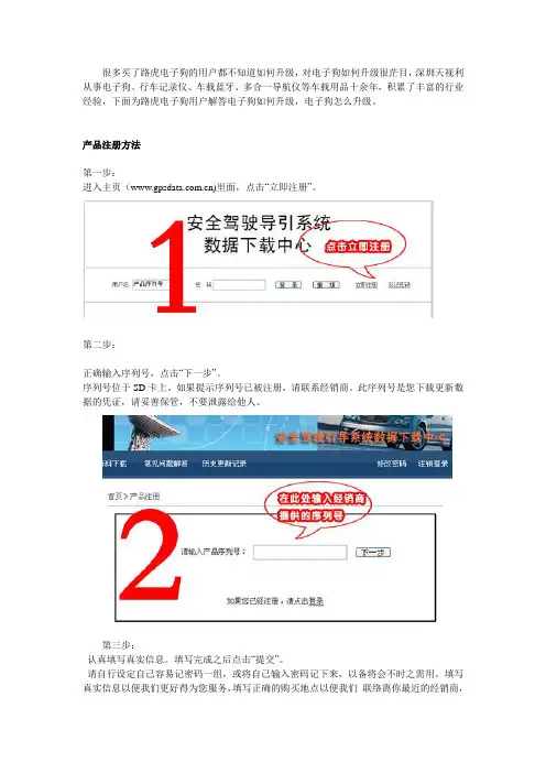
很多买了路虎电子狗的用户都不知道如何升级,对电子狗如何升级很茫目,深圳天视利从事电子狗、行车记录仪、车载蓝牙、多合一导航仪等车载用品十余年,积累了丰富的行业经验,下面为路虎电子狗用户解答电子狗如何升级,电子狗怎么升级。
产品注册方法第一步:进入主页()里面,点击“立即注册”。
第二步:正确输入序列号,点击“下一步”。
序列号位于SD卡上。
如果提示序列号已被注册,请联系经销商。
此序列号是您下载更新数据的凭证,请妥善保管,不要泄露给他人。
第三步:认真填写真实信息。
填写完成之后点击“提交”。
请自行设定自己容易记密码一组,或将自己输入密码记下来,以备将会不时之需用。
填写真实信息以便我们更好得为您服务,填写正确的购买地点以便我们联络离你最近的经销商,协助你找到答案或排除你的问题。
“密码问题”与“问题答案”是您取回密码的方法之一,填写后不可更改。
第四步:注册完成之后请返回首页,您便可凭刚才注册的序列号登录。
下载符合自己机型的程序进行升级。
下次有新的更新,直接登录即可,无需重新注册。
更新说明:请您先阅读好更新说明,再进行操作。
(升级方法如与产品说明书内容有出入,则以网站为准,升级过程中如果遇到问题,请联系经销商协助解决)1.将设备与电脑连接,连接后如果设备屏幕上显示“OL”,说明已经正确连接。
2.运行升级包,弹出对话框,点击“下一步”。
3.确认设备已经连接好,然后点击“开始”,等待数分钟,直到弹出完毕对话框,则更新完毕。
(如下图)。
注意:更新过程中切勿断开连接!如果用户升级失败也可以访问/download.html这里面提供路虎电子狗多种型号升级数据包下载。
如有不懂的可以咨询在线客服为你解答疑问。
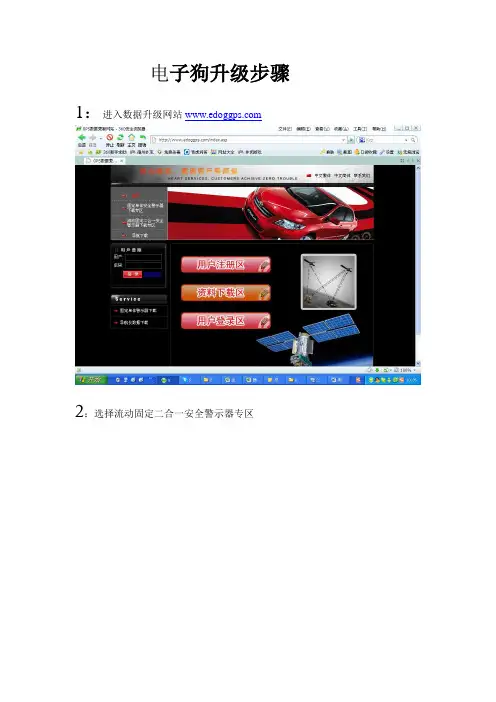
电子狗升级步骤1:进入数据升级网站2:选择流动固定二合一安全警示器专区3:在产品序列号里面输入电子狗后面的序列号如:75519509XXXX4:进入下载专区后有两个选择项:(1):在线更新(2):本地更新两种更新模式随便选择哪种都可以进行数据升级。
5:选择”下载链接”下面的点击此处下载就可以下载软件了,保存好路径。
6:如果选择在线更新,会有个.exe文件保存到你设的路径下面,双击下—点安装目录下面会弹出个电子狗数据更新软件文件夹里面有两个文件这有个安装电子狗驱动的的操作说明书,你只需按照这上面来操作就行到最后一步。
升级软件会自动生成到桌面,直接点击升级就可以。
7:如果选择本地更新;会有个本地下载.exe文件。
这里有五个文件第一个电子狗驱动文件,第二个是升级软件,第三个是数据文件,第四个是电子狗操作说明书,第五个是注意提醒文档。
解压后,如果以前没有装过电子狗驱动文件,请按以下操作实行。
用户第一次使用数据更新程序,安装驱动等。
第一步:用USB线插上电子狗,连上电脑。
右键单击“我的电脑”选择里面的设备管理器双击“端口如图:第二步:右键点击带黄色感叹号的STA2058/8058-COM Port选择第一个更新驱动程序选择从列表或指定位置安装如图:第三步:点击下一步进入硬件更新向导选择不要搜索。
我要自己选择要安装的驱动程序如图:第四步:点击下一步选择从磁盘安装如图:第五步:点击浏览路径:选择你要安装的驱动文件STM_STA2058_STA8058 vcom driver.inf 这到这个文件文件在下载的USB驱动文件包里面。
第六步:选择好路径后,点击确定第七步:点击下一步会弹出个警示框出来如图:第八步:点击是驱动正在更新,最后点击完成。
第九步:找到下载到的升级程序打开EDogSyncV1.3.exe 如图:第十步:点击本地更新会弹出让你选择升级数据的路径框如图:注意:路径要选择正确,一般数据升级文件会跟软件放在同一个目录第十一步:选择edog这个数据,点击打开,软件就会自动升级数据。
电子狗常见的问题爱的顾客朋友,感谢您光临本商城,以下是顾客们经常反映的一些问题,应该对你有很大的帮助。
你们的售后是怎么保证的:我们的产品质量和售后服务是相当到位的,全部产品直接来自厂家或总经销商,假一赔十,您可以绝对放心!所有产品,如有质量问题,均实行一月包换、一年保修、终身维修。
你们是怎么保证产品是原装正品:全国最大的四大电子狗厂商授权本商城官方直销(均有授权证书公布于网站),顾客们绝对放心您买到的产品绝对原装正品。
现在市场上已经出现了一些的假冒产品和商家,做的很象的,也把产品包装得很豪华。
我们在网站里作了相应的介绍和鉴别方法.你不管跟谁交易,都要问清楚有没有营业资格、有没有售后服务,问清楚能不能不满意退货。
收到货可以用固定电话或者短信查验防伪,如果是货到付款,请先开箱验货后再付款签收(本商城与顺丰快递签有合约,均可开箱验货再签收,这是您的权利。
)。
带电子狗的导航仪怎么升级:1、此类机子升级包括两个方面,即地图升级和固定点数据升级。
2、地图升级如果是正版的地图,那么升级的方法和费用是全国统一的,如果厂家有升级包提供给我们,我们会在论坛上公布,您可以免费下载。
如果不想出正版地图升级的费用,也可以免费下载我们的破解版3、如果要下破解版,只要直接到我们的电子狗论坛里注册回复后直接下载就行了。
(商城自有专业高速服务器,永久免费)。
4、地图的升级周期是比较长的,一般要半年左右才会有一次全面的升级,我们发给你们机子时所配的地图都是最新的,在半年内无需升级。
5、固定点数据的升级网站及升级步骤请参看说明书,盒子的底部或说明书均升级网址。
为什么有的固定点不提示:因为测速点是人工收集的,所以收集数据一定的周期性,因此,有个别不提示是正常的。
如果是新装的或者这个测速点是不带拍照的.那厂家可能没有收集进去。
(特别是先知的数据,是电子界最专业的,该收集的收集,不该收集的就不收集,该报限速的就报,不发报的就不报.目的只有一个--减少对车主的驾驶干扰!)测速点数据我们保证有效率在98%以上.为什么我们看到流动测速器却不报:(有很多买家拿到我们的电子狗后,自然会有些兴奋的感觉,第一反应就是装到车上进行测试,然而在测试的过程中,居然发现有些装探测器的地方,电子狗居然不报警,所以就马上打电话到我们售后进行这样那样的咨询,最后还得把机器回寄给我们进行检测,然而我们技术进行检测的时候97%以上都是没有问题的,所以我们现在总结一下机器不报警的几个原因,供大家进行参考。
G3数据升级说明
预警产品数据会定期在网站更新,请客户及时升级。
方法如下:一、机型确认
请先确认机器型号,机器外形和型号标签如图1、图2所示:
(图1)
(图2)
二、升级数据
温馨提示:使用升级程序时请先退出杀毒软件,杀毒软件将有可能阻止本程序运行或无法下载数据。
同时,运行程序时需从网络自动下载数据,电脑必须能正常连接网络。
1. 用USB数据线把机器连接到电脑,正常连接成功后,稍等片刻机器屏幕一
直显示字样。
同时,PC端“我的电脑”里将出现可移动磁盘
,并且可移动磁盘自动在桌面打开,打开后有如下文件,图3所示:
(图3)
2.打开文件夹,双击升级程序,弹出对话框,
图4所示:
(图4)
3.点击“确定”,直接打开升级程序。
图5所示:
(图5)
4.点击升级菜单左下角的按钮,开始升级数据,图6所示:
(图6)
6.升级过程中不要操作机器或拔掉USB数据线,等待升级结束,弹出菜单。
图7
所示:
(图7)
7.升级完成后机器会自动启动,开始播报语音提示。
点“确定”退出升级程序。
8.拔掉USB数据线,升级完成。
路战神电子狗介绍关于我们路战神电子为台湾著名雷达制造厂商---雷瑞雷达高新科技技术企业所属全资子公司,多年来专业致力于GPS汽车安全行车行业的科研,制造和销售。
产品远销于欧美州和日本。
2005年并在中国大中华地区成立深圳和广州分公司,产品分销与中国内地各级市场,并在华中西北和华东地区设有办事销售和服务处。
公司经营理念以人为本,以客为尊。
现拥有一批研发设计,台湾式生产管理和销售高素质专业人才,公司拥有本行业标准的先进生产装配线和各进口专业测调试仪器。
电子狗=固定+流动介绍:目前市场大部分的电子狗都是固定+流动二合一电子狗。
一.固定:指凡是能看见的交警道路测速、拍照的所有不动的固定电子眼,包括:红绿灯照相、压线照相、电子监控等等!早期厂家通过在各固定电子眼的周边埋天线的方式发射信号,电子狗里面安装接收电路的方式来报警,由于需要定期给发射器换电池,其维护成本繁重!故该方式已淘汰!目前电子狗的固定报警全采用GPS数据播报,厂家采集车队到全国各地的固定电子眼进行经、纬度坐标采集,进行统一编程,储蓄到电子狗的内存芯片里。
顾客汽车的里电子狗与卫星通讯,准确找到目前的位置,当汽车行驶到前方电子眼的时候,储存器内的数据就会播报该电子眼的详细数据,例如:“前方为固定测速路段,限速80公里”等等。
固定播报的优劣取决于各厂家采集电子眼数据的详细程度,另外每年新增的电子眼,也需要厂家定时去新增采集,目前国内有采集实力的厂家为:征服者、凌速、先知、善领、君安。
固定播报的优劣另外还取决于厂家是否定期升级网站数据,升级的越频繁,代表数据的更新程度越快!目前路战神采用凌速数据,每15天定时在网站升级数据!终生免费!路战神升级网址:二.流动:指道路上面交警使用的流动警车雷达、流动架接雷达、手持测速雷达、固定测速雷达。
这些设备都会通过发射雷达波测试目标车辆的速度,如果超度将被拍罚款和扣分!目前测速雷达所用的频段主要有:X、K、Ka、Ku、LASER等。
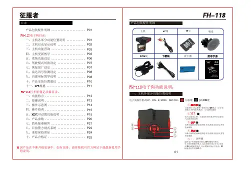
君安路虎LH-160 用户指导手册目录功能说明>前言>检查产品包装>产品结构说明>LED显示说明>产品功能说明>按键设定说明>语音响声含义说明数据下载更新说明>注册>下载与更新GPS状态>GPS主要规格说明>无法取得卫星信号因素>GPS异常警示状态目前警方制式系统与产品保修>目前警方制式系统>重要原厂保证需知>产品保修凭证>打假维权声明前言亲爱的用户您好:首先非常感谢你使用我们征服眼系列产品,除恭喜您挑选到好的产品外,也为您正确的选购有完善保固及有服务品质的产品,而替您庆幸不已,汽车雷达侦测器在全球各地虽行之有年,然而全球各地之汽车雷达业者良莠不齐,行销花招百出,广告夸大不实,已令广大消费者眼花缭乱无从选择,再加上各家公司对于商品本质之感度及侦搜范围,大多无专业仪器进行测试,而造成即使于市场知名度很高的商品,仍免有不堪使用之劣质商品充斥其中贩售,造成消费者人人只能自求多福,同样是雷达侦测器,为何我们就是比人家好?因为我们一直很用心,希望带给您行车更安全!本公司自成立以来,无论商品的品质保固,都做到每一位顾客有口皆碑外,诚实不夸大,诚实标价不欺骗,落实于每一位销售环节中,贵为市场之清流,堪称业界之表率,更领先全国销售同业,引进百万专业仪表检查仪器,严格把关,使得公司所行销之商品,有大幅度超越一般市销商品的品质与性能,进而使您购买到最优良的商品。
最后除再次感谢您的肯定与惠顾,也同时希望您能主动对本公司未尽周全之处指教,亦在此呼吁驾驶人安全第一,生命无价,又我们能期待所有使用者,都能详细技术手册,所谓知己知彼,对警方测速设备执勤原理及程序多一分了解,就多了一份安全与胜算,期盼每位驾驶员都能快快乐乐出门,平平安安回家。
祝:万事如意,事事顺心!>检查产品包装您所购买的GPS卫星定位雷达产品包装盒中应该包含以下的物件1.GPS主机2.车载充电器(输出12V)B连接线(用于数据下载更新)4.支架5. 说明书>产品结构说明1)待机状态显示说明①当前设定状态栏,分别显示:固定模式、雷达感度、雷达静音速度;②当前方向显示,未定位,则“东”“南”“西”“北”轮流闪烁显示;③卫星状态;未定位,搜索GPS信号,四个图标轮流显示,如图所示:④当前日期;⑤当前时间,定位后,冒号“:”闪烁;⑥当前车速;⑦车速单位;>LED显示说明2)雷达播报显示说明收到雷达信号时,下方显示当前雷达频段,语音播报对应的频段,雷达越强,显示越多,如图所示,为KA频强信号。
凯立德地图:开机(电子狗画面)―――点导航――点功能――点击VER 即可查看地图版本您可以进入系统设置模式,进入雷达感度设定,把感度值设定超高。
端口=8波特率=4800很简单。
比如下载一个凯立德地图。
分辨率当然是你机子的。
我前两天帮一个同事升级了地图。
我记得你们这个机子是端口号是2。
波特率是4800。
在地图中设置好就OK了。
装入卡中,导航设置中选择路径。
我在升级过程中发现一个问题。
我装了善领。
用善领再启动地图,居然地图无法使用。
无法定位和搜星。
5.更新教学步骤一▲关闭导航将导航开关切换至OFF步骤二▲将SD卡从导航机内取出并插至读卡器,将读卡器连接至电脑USB端口步骤三▲点选所需更新产品图进行更新如图一所示步骤四▲用户进入线上更新程式时,请依据本身所在位置,选择合适之伺服器进行下载,本产品由于采用最新辨识系统,在下载前不需要再进行任何注册,只要是本公司原厂出产之产品,再进行步骤三的程序后,即可按左图中的更新开始下载▲自动检测SD卡▲本线上更新作业所需时间会因使用者下载当时的网络传输速度的快慢而有所不同。
6.分离式室外机安装说明▲分离式的安装说明适用于蒙面侠800▲分离式主机安装,牵涉技术性安装考量,非专业安装,可能产生负面效能,本公司在此提供以下重要安全事项参考:※安装前,先拔除正极线上保险丝,当分离式主机安装完毕后,在装回原位置。
为确认电源的正负极性,请先安装负极,再安装正极。
1.水箱前镀铬饰条 , 一般分离式雷达主机安装位置,大致上会置于车头水箱罩内处(如图1,2),因为镀铬型水箱罩,会造成行进波形变化,或改变原有雷波的行进方向,等于具有外在的干扰因素,雷达行进的方向因而改变,进而影响安装于水箱罩内的分离式主机接收距离的表现。
2.水箱前空间不足 , 水箱室内除温度偏高外,水箱狭窄或空间不足固定分离式主机或集波放大器时,请选择安装于气霸进风口。
(如图1,2)3.导波管前障碍物 , 雷达导波管是一个集波器,就像电视天线,安装位置及安装角度都会影响接收效果。
电子狗一键升级方法2篇第一篇:电子狗一键升级方法电子狗是一种可以帮助驾驶员提高驾驶安全性的电子设备,它可以实时监测道路情况,提醒驾驶员避免危险。
为了使电子狗始终保持最新的信息和功能,需要进行升级。
以下是电子狗一键升级方法的步骤:步骤1:连接电脑和电子狗将电子狗与电脑连接,并打开电子狗的电源。
在电脑上打开电子狗升级软件,并等待软件检测到电子狗。
步骤2:选择升级文件从电子狗升级软件提供的升级文件列表中选择最新的文件,然后点击“下载”按钮。
在下载完成后,点击“确定”按钮,将选择的文件保存到电脑上。
步骤3:开始升级点击“开始升级”按钮,软件会提示您确认是否开始升级。
确认后,升级程序将自动运行,将升级文件下载到电子狗中。
在升级过程中,请勿关闭电子狗和电脑的电源,否则可能会导致升级失败。
步骤4:升级完成当升级完成后,电子狗将会自动重启。
此时,可以拔掉电子狗和电脑之间的连接线并关闭电脑。
升级完成后,即可以享受到最新的电子狗功能和道路信息。
注意事项:1. 请确保您的电脑连接到网络,并且升级软件和升级文件是从官方网站下载的,以确保升级的安全性。
2. 在升级过程中,请勿关闭电子狗和电脑的电源,否则可能会导致升级失败。
3. 如果您的电子狗无法升级,可能是因为电子狗内存已满,请清空内存空间并重试升级过程。
第二篇:电子狗一键升级方法(另一种)电子狗是一种可以帮助驾驶员保持行车安全的工具,使用过程中,需要定期对电子狗进行升级,以获得更加精确和实用的道路信息,以下是电子狗一键升级方法的另一种步骤:步骤1:下载电子狗升级软件首先需要从电子狗官方网站下载电子狗升级软件,然后将其保存到电脑上。
安装完成后,使用数据线将电子狗与电脑相连。
步骤2:打开升级软件打开电子狗升级软件,选择“升级”选项,然后将电子狗与电脑相连。
软件会自动识别当前连接的电子狗型号和软件版本。
然后,选择最新的电子狗升级文件,并点击“下载”按钮。
步骤3:开始升级待下载完成后,启动升级程序,在确认升级文件后,点击“升级”按钮开始升级,此时,升级程序将自动完成电子狗的更新,电子狗将自动重启。
征服者电子狗网站升级
首先到征服者指定的升级网站,根据你电脑的配置下载相关的升级软件。
电脑的配置在桌面上点击:我的电脑,然后点击鼠标右键,可以看到有属性,点击属性,就可以看到你的电脑相关配置。
根据电脑的配置系统,下载t征服者升级网站左边相对应方框里的升级软件,下载完后进行安装,安装成功之后电脑重启一下,然后将导航机子连接电脑,点击征服者升级网站上与机子相对应的机型图片升级即可。
希望可以帮到你。