OSPF邻居明文认证配置
- 格式:doc
- 大小:60.00 KB
- 文档页数:4
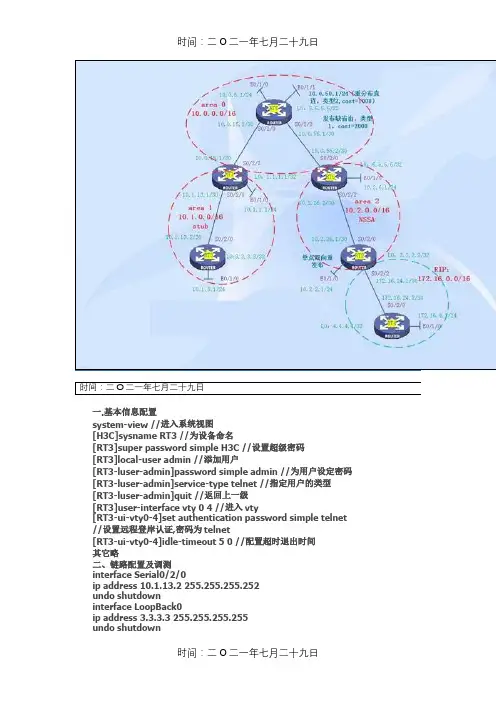
时间:二O二一年七月二十九日一.基本信息配置system-view //进入系统视图[H3C]sysname RT3 //为设备命名[RT3]super password simple H3C //设置超级密码[RT3]local-user admin //添加用户[RT3-luser-admin]password simple admin //为用户设定密码[RT3-luser-admin]service-type telnet //指定用户的类型[RT3-luser-admin]quit //返回上一级[RT3]user-interface vty 0 4 //进入vty[RT3-ui-vty0-4]set authentication password simple telnet //设置远程登岸认证,密码为telnet[RT3-ui-vty0-4]idle-timeout 5 0 //配置超时退出时间其它略二、链路配置及调测interface Serial0/2/0ip address 10.1.13.2 255.255.255.252undo shutdowninterface LoopBack0ip address 3.3.3.3 255.255.255.255undo shutdowninterface Ethernet0/1/0ip address 10.1.3.1 255.255.255.0undo shutdown其它略三、OSPF多区域及RIP配置[RT3]ospf 1 router-id 3.3.3.3 //配置OSPF ROUTER-IDsilent-interface all //配置所有端口为主动接口undo silent-interface Serial0/2/0 //关闭此接口的主动接口undo silent-interface Serial0/2/2area 1 //OSPF区域,可以写成点分十进制 0.0.0.1network 3.3.3.3 0.0.0.0 //宣告OSPF的网段network 10.1.13.0 0.0.0.3network 10.1.3.0 0.0.0.255[RT1]ospf 1 router-id 1.1.1.1silent-interface allundo silent-interface Serial0/2/0undo silent-interface Serial0/2/2area 0network 10.0.15.0 0.0.0.3network 1.1.1.1 0.0.0.0area 1network 10.1.13.0 0.0.0.3network 10.1.1.0 0.0.0.255[RT5]ospf 1 router-id 5.5.5.5silent-interface allundo silent-interface Serial0/2/0undo silent-interface Serial0/2/2area 0network 10.0.15.0 0.0.0.3network 5.5.5.5 0.0.0.0network 10.0.5.0 0.0.0.255network 10.0.56.0 0.0.0.3[RT6]ospf 1 router-id 6.6.6.6silent-interface allundo silent-interface Serial0/2/0undo silent-interface Serial0/2/2area 0network 10.0.56.0 0.0.0.3network 6.6.6.6 0.0.0.0area 2network 10.2.6.0 0.0.0.255network 10.2.26.0 0.0.0.3[RT2]ospf 1 router-id 2.2.2.2silent-interface allundo silent-interface Serial0/2/2area 2network 10.2.26.0 0.0.0.3network 2.2.2.2 0.0.0.0network 10.2.2.1 0.0.0.255rip //启动RIPundo summary //关闭自动汇总version 2 //RIPV2network 172.16.0.0 //宣告RIP的网段silent-interface all //配置所有接口为主动接口undo silent-interface Serial0/2/3 //将接口不设为主动接口[RT4]ripundo summaryversion 2network 172.16.0.0network 4.0.0.0silent-interface allundo silent-interface Serial0/2/1四、OSPF重分布外部路由及下发缺省路由[RT5]ospf 1area 0import-route direct cost 1000 type 2 //重分布直连路由default-route-advertise always //下发缺省路由default cost 2000 //指定缺省路由的COST为2000default type 1 //指定下发的缺省路由为类型1[RT2]ospf 1area 2import-route rip 1 cost 1000 //重分布RIP到OSPFripimport-route ospf 1 cost 5 //重分布OSPF到RIP五、OSPF特殊区域配置及路由汇总[RT3]ospf 1area 1stub //配置为STUB区域[RT1]ospf 1area 1stub no-summary //配置完全STUB区域abr-summary 10.1.0.0 255.255.0.0 //区域内汇总[RT6]ospf 1area 2nssa no-summary //配置完全NSSA区域abr-summary 10.2.0.0 255.255.0.0 //区域内汇总[RT2]ospf 1area 2nssa //配置NSSA区域asbr-summary 172.16.0.0 255.255.0.0 cost 1000 //外部路由汇总六、OSPF虚链路system-view[Sysname] ospf 100[Sysname-ospf-100] area 2[Sysname-ospf-100-area-0.0.0.2] vlink-peer 1.1.1.1 指定对方的ROUTER-ID [Sysname-ospf-100-area-0.0.0.2]vlink-peer 1.1.1.1 md5 10 cipher H3C 虚链路MD5认证vlink-peer 1.1.1.1 simple cipher H3C 虚链路明文认证虚链路的另一端也类似配置display ospf vlink //显示虚链路七、OSPF认证[RT1]ospf 1[RT1ospf-1]area 1[RT1-ospf-1-area-0.0.0.1]authentication-mode md5[RT1-ospf-1-area-0.0.0.1]quit[RT1-ospf-1]quit[RT1]int s0/2/0[RT1-Serial0/2/0]ospf authentication-mode md5 10 cipher H3C [RT3]ospf 1[RT3ospf-1]area 1[RT3-ospf-1-area-0.0.0.1]authentication-mode md5[RT3-ospf-1-area-0.0.0.1]quit[RT3-ospf-1]quit[RT3]int s0/2/0[RT3-Serial0/2/0]ospf authentication-mode md5 10 cipher H3C 或是采纳明文认证,配置方法与上类似authentication-mode simpleospf authentication-mode simple cipher H3C八、OSPF调测调试命令display ospf brief //显示OSPF的摘要信息display ospf cumulative //OSPF的统计信息display ospf interface //显示OSPF的接口信息display ospf peer //显示OSPF的邻居信息display ospf lsdb //显示OSPF的LSDBdisplay ospf routing //显示OSPF的路由信息display ospf error //显示OSPF的毛病信息reset ospf process //重启OSPF进程其它命令int e0/2/0ospf cost 1000 //修改OSPF的COST值 COST=10的8次方/带宽ospf network broadcast|nbma |p2mp |p2p //修改OSPF的网络类型ospf dr-priority 10 //修改接口的优先级,缺省为1九、H3C与CISCO的路由协议管理距离的区别:CISCO:H3C:时间:二O二一年七月二十九日。
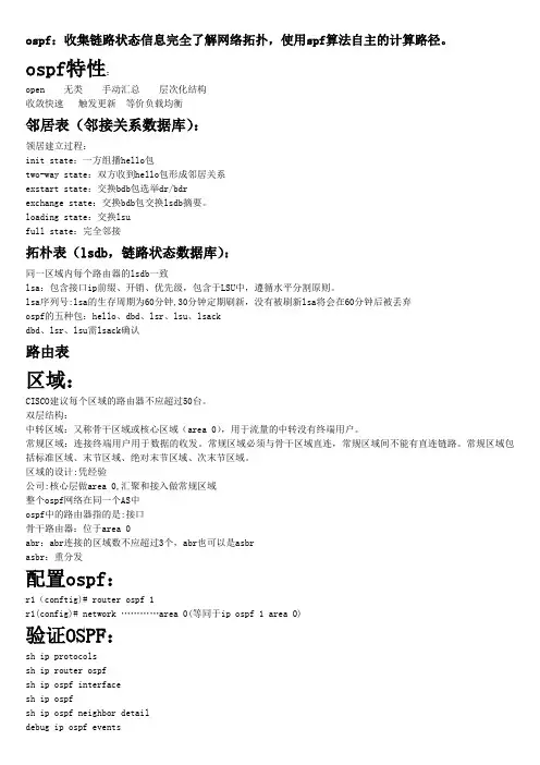
ospf:收集链路状态信息完全了解网络拓扑,使用spf算法自主的计算路径。
ospf特性:open 无类手动汇总层次化结构收敛快速触发更新等价负载均衡邻居表(邻接关系数据库):领居建立过程:init state:一方组播hello包two-way state:双方收到hello包形成邻居关系exstart state:交换bdb包选举dr/bdrexchange state:交换bdb包交换lsdb摘要。
loading state:交换lsufull state:完全邻接拓朴表(lsdb,链路状态数据库):同一区域内每个路由器的lsdb一致lsa:包含接口ip前缀、开销、优先级,包含于LSU中,遵循水平分割原则。
lsa序列号:lsa的生存周期为60分钟,30分钟定期刷新,没有被刷新lsa将会在60分钟后被丢弃ospf的五种包:hello、dbd、lsr、lsu、lsackdbd、lsr、lsu需lsack确认路由表区域:CISCO建议每个区域的路由器不应超过50台。
双层结构:中转区域:又称骨干区域或核心区域(area 0),用于流量的中转没有终端用户。
常规区域:连接终端用户用于数据的收发。
常规区域必须与骨干区域直连,常规区域间不能有直连链路。
常规区域包括标准区域、末节区域、绝对末节区域、次末节区域。
区域的设计:凭经验公司:核心层做area 0,汇聚和接入做常规区域整个ospf网络在同一个AS中ospf中的路由器指的是:接口骨干路由器:位于area 0abr:abr连接的区域数不应超过3个,abr也可以是asbrasbr:重分发配置ospf:r1(conftig)# router ospf 1r1(config)# network …………area 0(等同于ip ospf 1 area 0)验证OSPF:sh ip protocolssh ip router ospfsh ip ospf interfacesh ip ospfsh ip ospf neighbor detaildebug ip ospf eventsdebug ip ospf adjospf的网络类型(dead time=4*hello time)点到点(PPP、HDLC串口):直接邻接,hello-time 10s2、广播(LAN):选dr/bdr,hello-time 10sdrother与dr/bdr:邻接;drother之间:领居dr组播224.0.0.5;drother组播224.0.0.6dr的轮选:数值最大接口优先级(默认值1)ip ospf priority ?2、rid:环回地址、物理接口ip地址router-id ip address(次于优先级,ip地址可以为存在或不存在,不能指定其他路由器已有IP)dr稳定性,先到先得clear ip ospf process(清除ospf进程让dr重选;清除ospf进程邻居关系重新形成)3、ospf在nbma网络运行的公有模式:1、nbma:默认模式hello time 30s在hub-spoke拓朴,选dr/bdr,同一子网,中心路由器为dr/bdr边缘路由器(spoke)相互之间要做dlci的映射(dlci复用)中心路由器手动指定领居(如:nei 192.168.1.2 priority 0把spoke优先级设为0)2、p2m:hello time 30s同一子网,不选dr/bdr,多点fr子接口无需修改网络类型,邻接关系可以正常建立,但路由就没法学到,因此建议在多点fr子接口修改网络类型。
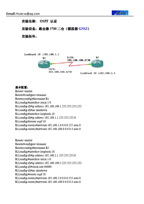
实验名称:OSPF 认证实验设备:路由器3700二台(模拟器GNS3)实验拓补:基本配置:Router>enableRouter#configure terminalRouter(config)#hostname R1R1(config)#interface serial 1/0R1(config-if)#ip address 192.168.100.1 255.255.255.252R1(config-if)#no shutdownR1(config)#interface loopback 10R1(config-if)#ip address 192.168.1.1 255.255.255.0R1(config)#router ospf 10R1(config-router)#network 192.168.1.0 0.0.0.255 area 0R1(config-router)#network 192.168.100.0 0.0.0.3 area 0 Router>enableRouter#configure terminalRouter(config)#hostname R2R2(config)#interface loopback 10R2(config-if)#ip address 192.168.2.1 255.255.255.0R2(config)#interface serial 1/0R2(config-if)#ip address 192.168.100.2 255.255.255.252R2(config-if)#clock rate 64000R2(config-if)#no shutdownR2(config)#router ospf 20R2(config-router)#network 192.168.2.0 0.0.0.255 area 0R2(config-router)#network 192.168.100.0 0.0.0.3 area 0认证方式:一、明文认证R1 配置R1(config)#interface serial 1/0R1(config-if)#ip ospf authentication /**在所有参与OSPF进程的接口启用明文验证R1(config-if)#ip ospf authentication-key cisco /**设置明文口令R1(config)#interface loopback 10R1(config-if)#ip ospf authenticationR1(config-if)#ip ospf authentication-key ciscoR1(config)#router ospf 10R1(config-router)#area 0 authentication /**声明在Area 0 使用明文验证R2配置R2(config)#interface serial 1/0R2(config-if)#ip ospf authenticationR2(config-if)#ip ospf authentication-key ciscoR2(config)#interface loopback 10R2(config-if)#ip ospf authenticationR2(config-if)#ip ospf authentication-key ciscoR2(config)#router ospf 20R2(config-router)#area 0 authentication二、MD5认证R1 配置R1(config)#interface serial 1/0R1(config-if)#no ip ospf authentication-key /**取消以前的明文密码R1(config-if)#ip ospf authentication message-digest /**启用MD5的密文验证R1(config-if)#ip ospf message-digest-key 1 md5 cisco /**设置密文验证的口令R1(config)#interface loopback 10R1(config-if)#no ip ospf authentication-keyR1(config-if)#ip ospf authentication message-digestR1(config-if)#ip ospf message-digest-key 1 md5 ciscoR1(config)#router ospf 10R1(config-router)#area 0 authentication message-digest /**声明Area 0 使用密文验证R2 配置R2(config)#interface serial 1/0R2(config-if)#no ip ospf authentication-keyR2(config-if)#ip ospf authentication message-digestR2(config-if)#ip ospf message-digest-key 1 md5 ciscoR2(config)#interface loopback 10R2(config-if)#no ip ospf authentication-keyR2(config-if)#ip ospf authentication message-digestR2(config-if)#ip ospf message-digest-key 1 md5 ciscoR2(config)#router ospf 20R2(config-router)#area 0 authentication message-digestR2#show ip ospf interface serial 1/0 /** 查看配置的验证。
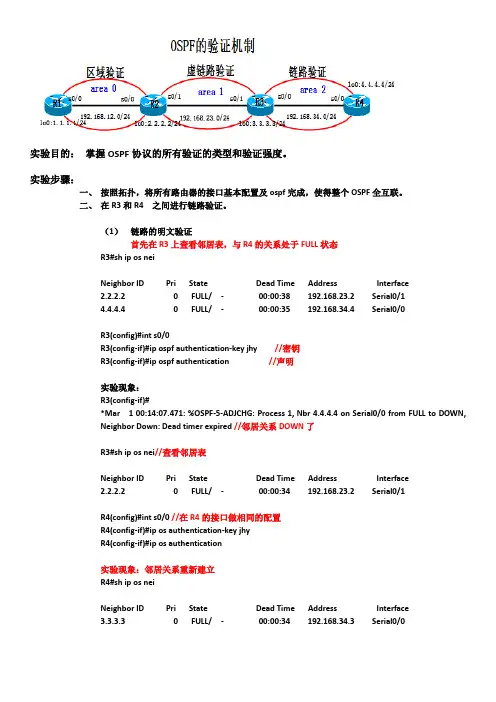
实验目的:掌握OSPF协议的所有验证的类型和验证强度。
实验步骤:一、按照拓扑,将所有路由器的接口基本配置及ospf完成,使得整个OSPF全互联。
二、在R3和R4 之间进行链路验证。
(1)链路的明文验证首先在R3上查看邻居表,与R4的关系处于FULL状态R3#sh ip os neiNeighbor ID Pri State Dead Time Address Interface2.2.2.2 0 FULL/ - 00:00:38 192.168.23.2 Serial0/14.4.4.4 0 FULL/ - 00:00:35 192.168.34.4 Serial0/0R3(config)#int s0/0R3(config-if)#ip ospf authentication-key jhy //密钥R3(config-if)#ip ospf authentication //声明实验现象:R3(config-if)#*Mar 1 00:14:07.471: %OSPF-5-ADJCHG: Process 1, Nbr 4.4.4.4 on Serial0/0 from FULL to DOWN,Neighbor Down: Dead timer expired //邻居关系DOWN了R3#sh ip os nei//查看邻居表Neighbor ID Pri State Dead Time Address Interface2.2.2.2 0 FULL/ - 00:00:34 192.168.23.2 Serial0/1R4(config)#int s0/0 //在R4的接口做相同的配置R4(config-if)#ip os authentication-key jhyR4(config-if)#ip os authentication实验现象:邻居关系重新建立R4#sh ip os neiNeighbor ID Pri State Dead Time Address Interface3.3.3.3 0 FULL/ - 00:00:34 192.168.34.3 Serial0/0(2)链路的密文验证R3(config-if)#ip os message-digest-key 1 md5 jhy//密钥R3(config-if)#ip os authentication message-digest //声明R4(config-if)#ip os message-digest-key 1 md5 jhyR4(config-if)#ip os authentication message-digest三、Area 0 的区域验证。
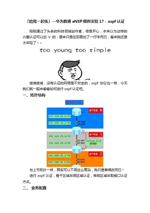
「陪我一起练」—华为数通eNSP模拟实验17:ospf认证刚刚通过了头条的科技领域创作者,很是开心,本来以为这样的兴趣认证可以加V的,原来只是在后面加了一行字而已,看来我还是太年轻了!~继续继续,没有认证的网络是不安全的,ospf协议也一样,今天我们就一起来看看如何进行ospf认证吧。
一、拓扑结构与上节拓扑一样,其实可以不用这么复杂,我只是懒得改而已!进行ospf认证,骨干区域采用区域认证,常规区域采取接口认证方式。
二、业务配置上节的配置保持不变,下面只帖出新增加(高亮)的认证命令。
R1路由器ospf区域(area0)认证认证方式md5,cipher为密文显示,密码为fight。
R2路由器ospf区域(area0)认证认证方式与R1路由器相同。
R2路由器ospf接口(area1)认证认证方式simple(明文),密码为addoil。
R3路由器ospf接口(area1)认证与R2路由器认证方式及密码相同。
请注意虚链路相当于是骨干区域area 0的延伸,那么骨干区域做了认证,延伸部分的虚链路也需要参与认证,R3作为虚链路的端点,同样配置区域认证。
虚链路area 0区域认证与R1和R2路由器认证方式及密码相同。
Area 2区域不做认证,R4路由器不需要配置。
以上命令即实现了ospf的认证功能。
三、配置验证配置验证也是比较简单检查相同区域内是否均配置了认证、邻居关系知否建立、是否学习到路由等。
还可以使用dis ospf brief命令,查看加密方式。
四、实验结论Ospf认证主要有两种区域认证和接口认证。
Ospf认证方式不建议采用simple(明文)方式,此方式认证密码会以明文的方式包含于ospf报文中,很不安全,推荐使用md5方式。
上图是我配置好之后做的抓包,在报文中明显能够看到认证密码为“addoil”。
而md5加密方式的密码是无法破解的。
请区分认证方式和密码显示方式是不同的概念。
一旦骨干区域(area 0)开启了区域认证,虚链路的端点设备也同样要开启area 0的区域认证,否则虚链路无法建立。
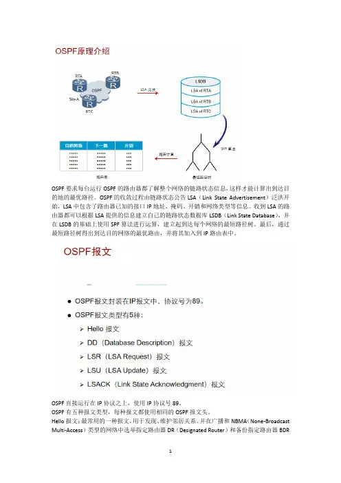
OSPF要求每台运行OSPF的路由器都了解整个网络的链路状态信息,这样才能计算出到达目的地的最优路径。
OSPF的收敛过程由链路状态公告LSA(Link State Advertisement)泛洪开始,LSA中包含了路由器已知的接口IP地址、掩码、开销和网络类型等信息。
收到LSA的路由器都可以根据LSA提供的信息建立自己的链路状态数据库LSDB(Link State Database),并在LSDB的基础上使用SPF算法进行运算,建立起到达每个网络的最短路径树。
最后,通过最短路径树得出到达目的网络的最优路由,并将其加入到IP路由表中。
OSPF直接运行在IP协议之上,使用IP协议号89。
OSPF有五种报文类型,每种报文都使用相同的OSPF报文头。
Hello报文:最常用的一种报文,用于发现、维护邻居关系。
并在广播和NBMA(None-Broadcast Multi-Access)类型的网络中选举指定路由器DR(Designated Router)和备份指定路由器BDR(Backup Designated Router)。
DD报文:两台路由器进行LSDB数据库同步时,用DD报文来描述自己的LSDB。
DD报文的内容包括LSDB中每一条LSA的头部(LSA的头部可以唯一标识一条LSA)。
LSA头部只占一条LSA的整个数据量的一小部分,所以,这样就可以减少路由器之间的协议报文流量。
LSR报文:两台路由器互相交换过DD报文之后,知道对端的路由器有哪些LSA是本地LSDB 所缺少的,这时需要发送LSR报文向对方请求缺少的LSA,LSR只包含了所需要的LSA的摘要信息。
LSU报文:用来向对端路由器发送所需要的LSA。
LSACK报文:用来对接收到的LSU报文进行确认。
邻居和邻接关系建立的过程如下:Down:这是邻居的初始状态,表示没有从邻居收到任何信息。
Attempt:此状态只在NBMA网络上存在,表示没有收到邻居的任何信息,但是已经周期性的向邻居发送报文,发送间隔为HelloInterval。
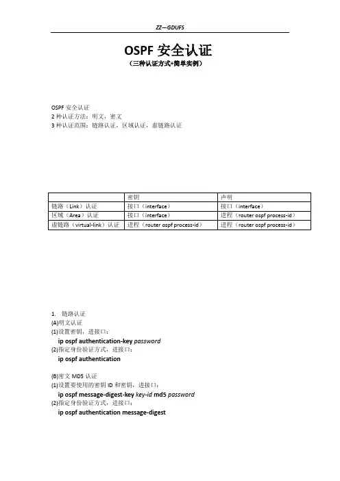
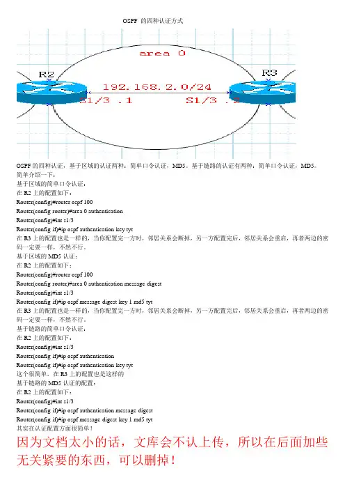
OSPF 的四种认证方式OSPF的四种认证,基于区域的认证两种:简单口令认证,MD5。
基于链路的认证有两种:简单口令认证,MD5。
简单介绍一下:基于区域的简单口令认证:在R2上的配置如下:Router(config)#router ospf 100Router(config-router)#area 0 authenticationRouter(config)#int s1/3Router(config-if)#ip ospf authentication-key tyt在R3上的配置也是一样的,当你配置完一方时,邻居关系会断掉,另一方配置完后,邻居关系会重启,再者两边的密码一定要一样,不然不行。
基于区域的MD5认证:在R2上的配置如下:Router(config)#router ospf 100Router(config-router)#area 0 authentication message-digestRouter(config)#int s1/3Router(config-if)#ip ospf message-digest-key 1 md5 tyt在R3上的配置也是一样的,当你配置完一方时,邻居关系会断掉,另一方配置完后,邻居关系会重启,再者两边的密码一定要一样,不然不行。
基于链路的简单口令认证:在R2上的配置如下:Router(config)#int s1/3Router(config-if)#ip ospf authenticationRouter(config-if)#ip ospf authentication-key tyt这个很简单,在R3上的配置也是这样的基于链路的MD5认证的配置:在R2上的配置如下:Router(config)#int s1/3Router(config-if)#ip ospf authentication message-digestRouter(config-if)#ip ospf message-digest-key 1 md5 tyt其实在认证配置方面很简单!因为文档太小的话,文库会不认上传,所以在后面加些无关紧要的东西,可以删掉!实验 1-2:在NAT中使用Access List 和Route Maps【实验目的】:在本次实验中,你需要使用网络地址转换(NAT)去允许内网路由器(PxR3 和 PxR4)从TFTP服务器下载配置文件为了完成本次实验,你需要完成下列任务:∙建立在NAT中需要使用的访问控制列表∙在NAT中使用ROUTE-MAPS执行分开的并发地址转换。
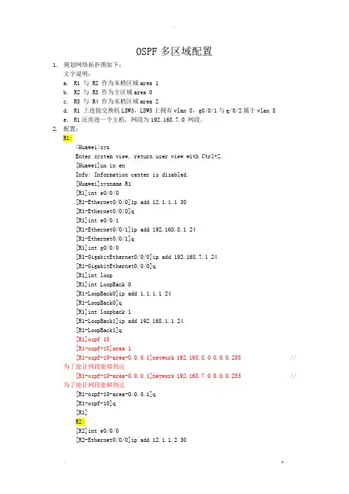
OSPF多区域配置1.规划网络拓扑图如下:文字说明:a.R1 与 R2 作为末梢区域area 1b.R2 与 R3 作为主区域area 0c.R3 与 R4 作为末梢区域area 2d.R1 上连接交换机LSW3,LSW3上拥有vlan 8,g0/0/1与g/0/2属于vlan 8e.R1还直连一个主机,网段为192.168.7.0 网段。
2.配置:R1:<Huawei>sysEnter system view, return user view with Ctrl+Z.[Huawei]un in enInfo: Information center is disabled.[Huawei]sysname R1[R1]int e0/0/0[R1-Ethernet0/0/0]ip add 12.1.1.1 30[R1-Ethernet0/0/0]q[R1]int e0/0/1[R1-Ethernet0/0/1]ip add 192.168.8.1 24[R1-Ethernet0/0/1]q[R1]int g0/0/0[R1-GigabitEthernet0/0/0]ip add 192.168.7.1 24[R1-GigabitEthernet0/0/0]q[R1]int loop[R1]int LoopBack 0[R1-LoopBack0]ip add 1.1.1.1 24[R1-LoopBack0]q[R1]int loopback 1[R1-LoopBack1]ip add 192.168.1.1 24[R1-LoopBack1]q[R1]ospf 10[R1-ospf-10]area 1[R1-ospf-10-area-0.0.0.1]network 192.168.8.0 0.0.0.255 //为了能让网段能够到达[R1-ospf-10-area-0.0.0.1]network 192.168.7.0 0.0.0.255 //为了能让网段能够到达[R1-ospf-10-area-0.0.0.1]q[R1-ospf-10]q[R1]R2:[R2]int e0/0/0[R2-Ethernet0/0/0]ip add 12.1.1.2 30[R2-Ethernet0/0/0]int e0/0/1[R2-Ethernet0/0/1]ip add 23.1.1.1 30 [R2-Ethernet0/0/1]q[R2]int loopback 0[R2-LoopBack0]ip add 2.2.2.2 24[R2-LoopBack0]q[R2]int loopback 1[R2-LoopBack1]ip add 192.168.2.1 24 [R2-LoopBack1]q[R2]ospf 10[R2-ospf-10]area 1[R2-ospf-10-area-0.0.0.1]q[R2-ospf-10]area 0[R2-ospf-10-area-0.0.0.0]q[R2-ospf-10]q[R2]R3:[Huawei]sysname R3[R3]int e0/0/0[R3-Ethernet0/0/0]ip add 34.1.1.1 30 [R3-Ethernet0/0/0]int e0/0/1[R3-Ethernet0/0/1]ip add 23.1.1.2 30 [R3-Ethernet0/0/1]q[R3]int loopback 0[R3-LoopBack0]ip add 3.3.3.3 24[R3-LoopBack0]q[R3]int loopback 1[R3-LoopBack1]ip add 192.168.3.1 24 [R3-LoopBack1]q[R3]ospf 10[R3-ospf-10]area 2[R3-ospf-10-area-0.0.0.2]q[R3-ospf-10]area 0[R3-ospf-10-area-0.0.0.0]q[R3-ospf-10]q[R3]R4:[Huawei]sysname R4[R4]int e0/0/0[R4-Ethernet0/0/0]ip add 34.1.1.2 30 [R4-Ethernet0/0/0]q[R4]int loopback 0[R4-LoopBack0]ip add 4.4.4.4 24[R4-LoopBack0]q[R4]int loopback 1[R4-LoopBack1]ip add 192.168.4.1 24[R4-LoopBack1]q[R4]ospf 10[R4-ospf-10]area 2[R4-ospf-10-area-0.0.0.2]q[R4-ospf-10]q[R4]从PC端ping各个路由器的route idPing 1.1.1.1: 32 data bytes, Press Ctrl_C to break From 1.1.1.1: bytes=32 seq=1 ttl=255 time=31 ms From 1.1.1.1: bytes=32 seq=2 ttl=255 time=15 ms From 1.1.1.1: bytes=32 seq=3 ttl=255 time=16 ms From 1.1.1.1: bytes=32 seq=4 ttl=255 time=31 ms From 1.1.1.1: bytes=32 seq=5 ttl=255 time=16 ms--- 1.1.1.1 ping statistics ---5 packet(s) transmitted5 packet(s) received0.00% packet lossround-trip min/avg/ma* = 15/21/31 msPing 3.3.3.3: 32 data bytes, Press Ctrl_C to break From 3.3.3.3: bytes=32 seq=1 ttl=253 time=94 ms From 3.3.3.3: bytes=32 seq=2 ttl=253 time=109 ms From 3.3.3.3: bytes=32 seq=3 ttl=253 time=94 ms From 3.3.3.3: bytes=32 seq=4 ttl=253 time=94 ms From 3.3.3.3: bytes=32 seq=5 ttl=253 time=94 ms--- 3.3.3.3 ping statistics ---5 packet(s) transmitted5 packet(s) received0.00% packet lossround-trip min/avg/ma* = 94/97/109 msPing 4.4.4.4: 32 data bytes, Press Ctrl_C to break From 4.4.4.4: bytes=32 seq=1 ttl=252 time=156 ms From 4.4.4.4: bytes=32 seq=2 ttl=252 time=125 ms From 4.4.4.4: bytes=32 seq=3 ttl=252 time=109 ms From 4.4.4.4: bytes=32 seq=4 ttl=252 time=110 ms From 4.4.4.4: bytes=32 seq=5 ttl=252 time=141 ms --- 4.4.4.4 ping statistics ---5 packet(s) transmitted5 packet(s) received0.00% packet lossround-trip min/avg/ma* = 109/128/156 msPC>查看R2的路由表:3.配置R1与R2 链路认证,使用明文认证R1:[R1]int e0/0/0[R1-Ethernet0/0/0]ospf aut[R1-Ethernet0/0/0]ospf authentication-mode sim[R1-Ethernet0/0/0]ospf authentication-mode simple plain YP[R1-Ethernet0/0/0]q查看邻居路由:两个路由器链路密码不同断开认证邻居关系[R1]dis ospf peer briefPeer Statistic Information----------------------------------------------------------------------------Area Id Interface Neighbor id State0.0.0.1 Ethernet0/0/0 12.1.1.2Full----------------------------------------------------------------------------R2:[R2]int e0/0/0[R2-Ethernet0/0/0]ospf au[R2-Ethernet0/0/0]ospf authentication-mode simple plain YP[R2-Ethernet0/0/0]q查看邻居路由:两个路由器链路密码一样重新连接认证邻居关系[R2]dis ospf peer briefPeer Statistic Information----------------------------------------------------------------------------Area Id Interface Neighbor id State0.0.0.0 Ethernet0/0/1 34.1.1.1Full0.0.0.1 Ethernet0/0/0 12.1.1.1Full----------------------------------------------------------------------------4.配置R3与R4的区域认证,使用密文认证。
OSPF配置AS:在共同管理下的一组运行相同库有选择协议的路由器的集合为一个“自治系统”IGP:内部网关路由协议——用于在单一AS内决策路由,用来解决AS内部通信!EGP:外部网关路由协议——用于在多个AS之间执行路由,用来解决AS间通信!ospf基本配置:全局:router ospf +区域号指定ospf协议运行的接口以及所在的区域命令如下:network 网络地址反掩码area 区域号修改接口优先级:router ospf模式:IP ospf priority 数值优先级(0~255)设置为0时不参与选举DR为指定路由器,BDR为备份指定路由器!修改COST值:接口模式:IP ospf cost 数值(1~65535)数值小的优先级大。
查看ospf配置:路由表:show IP route邻居列表及状态:show IP router ospf neighborospf配置:show IP ospfospf 多区域配置ABR(区域边界路由器):连接一个或多个区域到骨干区域的路由器,并且这些路由器会作为间通信量的路由网关ASBR:(自治系统边界路由器):可以认为它是ospf域外部的通信量进入ospf域的网关路由器洪扩散。
●组成员LSA(LSA6):是用在OSPF协议的一个增强版本――组播OSPF协议(MOSPF协议)中的。
MOSPF协议将数据包从一个单一的源地址转发到多个目的地,或者是一组共享D类组播地址的成员。
●NSSA外部LSA(LSA7):是指在非纯末梢区域(Not-So-Stubby Area,NSSA)内始发于ASBR路由器的LSA通告。
NSSA外部LSA通告几乎和自主系统外部LSA通告是相同的。
只是不像自主系统外部LSA通告那样在整个OSPF自主系统内进行泛洪扩散,NSSA外部LSA通告仅仅在始发这个NSSA外部LSA通告的非纯末梢区域内部进行泛洪扩散。
●外部属性LSA(LSA8):是被提议作为运行内部BGP协议(iBGP协议)的另一种选择,以便用来传送BGP协议的信息穿过一个OSPF域。
华为技术命令(五)ospf配置命令配置命令【命令】abr-summary ip-address mask mask area area-id [ advertise |ITnotadvertise ]undo abr-summary address mask mask area area-id【视图】OSPF 视图【参数】ip-address 和mask:为网络IP 地址和掩码,点分十进制格式。
area-id:为区域号。
advertise:将到这一聚合网段路由的摘要信息广播出去。
notadvertise:不将到这一聚合网段路由的摘要信息广播出去。
【描述】abr-summary area 命令用来配置OSFP区域间路由聚合,undoITabr-summary area 命令用来取消区域间路由聚合。
缺省情况下,对区域间的路由不进行聚合。
需要注意的是:路由聚合功能只有在ABR 上配置才会生效。
【举例】# 定义聚合网段10.0.0.0 255.0.0.0 加入到区域2 中。
[Quidway-ospf] abr-summary 10.0.0.0 mask 255.0.0.0 area 2【命令】debugging ospf { event | packet [ ack | dd | hello | request | update ] |网络,技术, lsa | spf } undo debugging ospf { event | packet [ ack | dd | hello | request |update ] | lsa | spf }【视图】所有视图【参数】event:打开OSPF 事件信息调试开关lsa:打开OSPF LSA报文信息调试开关。
spf:打开OSPF 最小树计算信息调试开关。
packet:打开OSPF 报文信息调试开关。
ack:打开OSPF 响应报文信息调试开关。
dd:打开OSPF 数据描述报文信息调试开关。
步骤 1. 将R1 配置为使用OSPF 简单身份验证。
要在R1 上启用简单身份验证,请在全局配置提示符下使用router ospf 1 命令进入路由器配置模式。
然后发出area 0 authentication 命令以启用身份验证。
R1(config)#router ospf 1R1(config-router)#area 0 authentication00:02:30: %OSPF-5-ADJCHG: Process 1, Nbr 10.2.2.1 on Serial0/0/0 from FULL toDOWN, Neighbor Down: Dead timer expired00:02:30: %OSPF-5-ADJCHG: Process 1, Nbr 10.2.2.1 on Serial0/0/0 from FULL toDown: Interface down or detachedarea 0 authentication命令可对区域0 中的所有接口启用身份验证。
通常,在R1 上只需使用该命令便可成功配置身份验证,因为R1 无须支持任何其它类型的身份验证。
最后,您将看到一条说明R1 与R2 的相邻关系已解除的控制台消息。
R1 路由表中的所有OSPF 路由全都消失,直至它能够向R2 验证路由。
即使未配置口令,R1 仍会要求所有邻居在OSPF 路由消息和更新中使用身份验证。
要为R1 配置简单身份验证口令,请进入连接至R2 的链路所对应的接口配置模式。
然后发出 ip ospf authentication-key cisco123命令。
该命令将身份验证口令设置为cisco123。
R1(config-router)#interface S0/0/0R1(config-if)#ip ospf authentication-key cisco123步骤 2. 将R2 配置为使用OSPF 简单身份验证。
OSPF邻居明文认证配置
【实验名称】
OSPF 邻居明文认证配置
【实验目的】
掌握OSPF 的邻居明文认证配置。
【背景描述】
你是一名高级技术支持工程师,某企业的网络整个的网络环境是ospf。
为了安全起见,新加入的路由器要通过认证,请你给予支持。
【实现功能】
完成OSPF区域新成员加入的安全认证。
【实验拓扑】
【实验设备】
R2624路由器(2台)、V35DCE(1根)、V35DTE(1根)
【实验步骤】
第一步:基本配置
Red-Giant>en
Red-Giant#conf t
Red-Giant(config)#hostname R1 !更改路由器主机名
R1(config)#int s0
R1(config-if)#ip add 192.168.12.1 255.255.255.0 !为接口配置地址
R1(config-if)#clock rate 64000 ! 设置时钟速率在DTE端不用设置
R1(config-if)#no sh
R1(config)#iint loo 0
R1(config-if)#ip add 1.1.1.1 255.255.255.0 ! 配置loopback接口,保证路由更新的稳定Red-Giant>en
Red-Giant#conf t
Red-Giant(config)#hostname R2
R2(config)#int s0
R2(config-if)#ip add 192.168.12.2 255.255.255.0
R2(config-if)#no sh
R2(config)#int loo 0
R2(config-if)#ip add 2.2.2.2 255.255.255.0 ! 配置loopback接口,保证路由更新的稳定
验证测试:ping
R2#ping 192.168.12.1
Sending 5, 100-byte ICMP Echoes to 192.168.12.1, timeout is 2 seconds:
!!!!!
第二步:启动OSPF路由协议
R1(config)#router os 1
R1(config-router)#net 192.168.12.0 0.0.0.255 area 0
R1(config-router)# net 1.1.1.0 0 0.0.0.255 area 2
R1(config-router)#end
R2(config)#router os 1
R2(config-router)#net 192.168.12.0 0.0.0.255 area 0
R2(config-router)#net 2.2.2. 0 0.0.0.255 area 1
R2(config-router)#end
验证测试:R1# sh ip os nei (以R1为例)
Neighbor ID Pri State Dead Time Address Interface
2.2.2.2 1 FULL/ - 00:00:37 192.168.12.2 Serial0
第三步:配置OSPF验证
R1(config)#router os 1
R1(config-router)# area 0 authentication !配置区域间明文验证
R1(config)#int s0
R1(config-if)# ip os authentication-key star !配置验证密码
R2(config)#router os 1
R2(config-router)# area 0 authentication
R2(config)#int s0
R2(config-if)#ip os authentication-key star
验证测试:R1#debug ip os adj
OSPF:2 Way communication to neighbor 2.2.2.2
OSPF:send DBD packet to 192.168.12.2 seq 0x350 OSPF:Receive dbd from 2.2.2.2 seq 0xD7B
OSPF:NBR Negotiation Done we are the slave
OSPF:send DBD packet to 192.168.12.2 seq 0xD7B OSPF:Receive dbd from 2.2.2.2 seq 0xD7C
OSPF:send DBD packet to 192.168.12.2 seq 0xD7C OSPF:Database request to 2.2.2.2
OSPF:sent LS REQ packet to 192.168.12.2, length 12 OSPF:Receive dbd from 2.2.2.2 seq 0xD7D
OSPF:exchange done with neighbor 2.2.2.2
OSPF:send DBD packet to 192.168.12.2 seq 0xD7D OSPF:synchronized with neighbor 2.2.2.2, state:FULL OSPF:build router LSA for area 0, router ID 1.1.1.1
【注意事项】
●两个广域网接口在一区域里,验证的密码要一致
●不要忘记在DCE端配置时钟速率
【参考配置】
R2#sh run (以R2为例)
Building configuration...
Current configuration:
!
version 6.14(2)
!
hostname "R2"
!
ip subnet-zero
!
interface Loopback0
ip address 2.2.2.2 255.255.255.0
!
interface FastEthernet0
no ip address
shutdown
!
interface FastEthernet1
no ip address
shutdown
!
interface FastEthernet2
no ip address
shutdown
!
interface FastEthernet3
no ip address
shutdown
!
interface Serial0
ip address 192.168.12.2 255.255.255.0 ip ospf authentication-key star
interface Serial1
no ip address
shutdown
router ospf 1
network 192.168.12.0 0.0.0.255 area 0 network 2.2.2.0 0.0.0.255 area 1
area 0 authentication
ip classless
line con 0
line aux 0
line vty 0 4
login。