双玻安装手册
- 格式:pdf
- 大小:1.22 MB
- 文档页数:7
玻璃窗安装说明书Glass window, floor hinge door with glass window installation instruction一、安装前准备Ⅰ.Preparation before installation1、安装前,安装单位要准备好以下工具及材料:Before installation, the installation group should prepare the tools and materials as following:工具:电焊机、橡皮锤、铁锤、钢凿、对拔木楔、托线板、吊线坠、水平尺(或水平仪)、钢卷尺、角尺、灰线包、玻璃吸盘、冲击钻、硅胶枪。
Tools: electric welding machine, rubber hammer, hammer, steel chisel, wooden chock, board with line, line drop, level tape (or level instrument), steel tape, beam square, grey line bag, glass cupula, strike drill, silica gel gun.辅助材料:预埋铁件、电焊条、连接件、冲击钻头、硅胶。
Subsidiary materials: built-in iron, electric welding strip, connect piece, strike drill, silica gel.2、检查洞口尺寸是否与玻璃窗安装的要求相符。
Check whether the wall to wall dimension is coinciding with the glass window installation requirements.3、有预埋铁件的洞口,还要检查洞口内预埋铁件的构造、位置和数量能否满足安装要求。
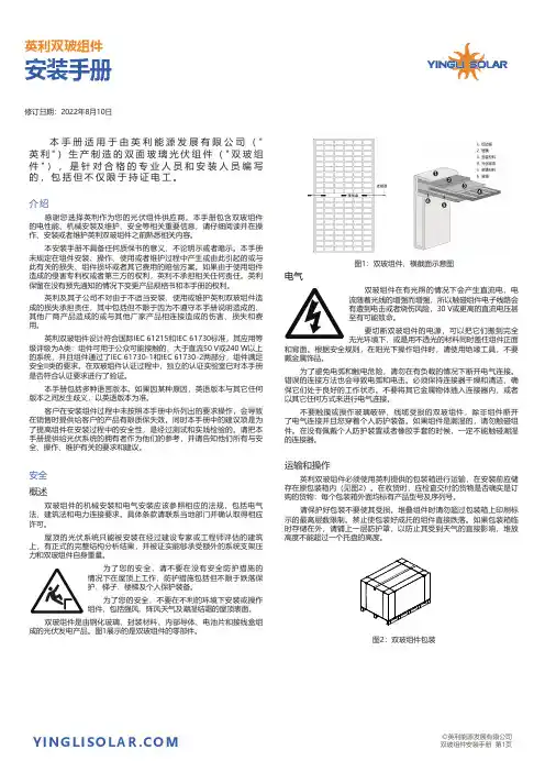
本手册适用于由英利能源发展有限公司("英利")生产制造的双面玻璃光伏组件("双玻组件"),是针对合格的专业人员和安装人员编写的,包括但不仅限于持证电工。
介绍感谢您选择英利作为您的光伏组件供应商。
本手册包含双玻组件的电性能、机械安装及维护、安全等相关重要信息,请仔细阅读并在操作、安装或者维护英利双玻组件之前熟悉相关内容。
本安装手册不具备任何质保书的意义,不论明示或者暗示。
本手册未规定在组件安装、操作、使用或者维护过程中产生或由此引起的或与此有关的损失、组件损坏或者其它费用的赔偿方案。
如果由于使用组件造成的侵害专利权或者第三方的权利,英利不承担相关任何责任。
英利保留在没有预先通知的情况下变更产品规格书和本手册的权利。
英利及其子公司不对由于不适当安装、使用或维护英利双玻组件造成的损失承担责任,其中包括但不限于因为不遵守本手册说明造成的、其他厂商产品造成的或与其他厂家产品相连接造成的伤害、损失和费用。
英利双玻组件设计符合国际IEC 61215和IEC 61730标准,其应用等级评级为A类:组件可用于公众可能接触的、大于直流50V或240W以上的系统,并且组件通过了IEC 61730-1和IEC 61730-2两部分,组件满足安全II类的要求。
在双玻组件认证过程中,独立的认证实验室已对本手册是否符合认证要求进行了验证。
本手册包括多种语言版本。
如果因某种原因,英语版本与其它任何版本之间发生歧义,以英语版本为准。
客户在安装组件过程中未按照本手册中所列出的要求操作,会导致在销售时提供给客户的产品有限质保失效。
同时本手册中的建议项是为了提高组件在安装过程中的安全性,是经过测试和实践检验的。
请把本手册提供给光伏系统的拥有者作为他们的参考,并请告知他们所有与安全、操作、维护有关的要求和建议。
安全概述双玻组件的机械安装和电气安装应该参照相应的法规,包括电气法、建筑法和电力连接要求。

双玻光伏组件3344455171919181918181 基本信息1.1 概述附录:应用产品 1.2 警告 2 安装 2.1 安装安全 2.2 安装条件选择 2.2.1 气候条件 2.2.2 安装地点选择 2.2.3 倾斜角的选择 2.3 安装方法介绍 3 接线和连接 5 电气特性 6 免责申明 4 维护和保养 4.1 外观检查 4.2 清洁 4.3 连接器和电缆线的检查 162.3.1 晶科双玻(无框)安装 102.3.2 晶科双玻(有框)安装 211. 基本信息1.1 概述首先感谢您选择使用晶科能源有限公司的太阳能电池组件,为了正确的安装和获得稳定的电力输出,安装及使用组件前请仔细阅读下面的安装说明。
请记住你使用的是一款发电产品,因此为了避免意外事故的发生,需要采用相应的安全措施。
请确保组件连接以后产生的电流、电压值在此阵列所连接的其他装置的电流、电压值的适用范围之内,太阳能组件能承受的最大系统电压为1500V DC。
如果组件安装在屋顶的话,必须安装具有一定防火能力的屋顶上,可以咨询当地的建筑部门来决定使用何种屋顶材料。
太阳能组件应用等级为A:危险电压(IEC 61730:高于50V DC; EN 61730:高于120V),危险功率(高于240W),根据EN IEC61730-1和-2标准,组件质量满足安全要求且安全等级为II。
1.2 警告●当组件暴露在太阳光或者其他光源下,组件内有直流电流产生,此时与组件的电气部分接触可能会发生触电危险。
●不要用镜子或透镜聚焦阳光照射到太阳电池组件上。
●太阳能电池组件的前玻璃和后玻璃具有保护组件的作用,破损的太阳能组件具有电危险性(电击和着火),这样的组件不能修复或维修,应该立即更换掉。
●普通室外条件下,组件产生的电流和电压与参数表中列出的有所不同。
参数表是在标准测试条件下测得,所以在确定光伏发电系统中其它部件的额定电压、导线容量、保险丝容量、控制器容量等和组件功率输出有关联的参数时,参照标在组件上的短路电流和开路电压的值,并按125%的值设计和安装。


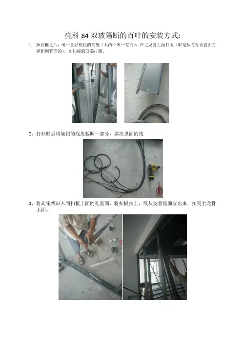
亮科84双玻隔断的百叶的安装方式:
1、插好框之后,统一量好旋钮的高度(大约一米一左右),在主龙骨上面打眼(眼是从龙骨正看面打
穿到侧看面的)。
在扣板的顶端打眼。
2、打好眼后将旋钮的线皮截断一部分,露出里面的线
3、将旋钮线串入到扣板上面的孔里面,将扣板扣上,线从龙骨里面穿出来,扣到主龙骨
上面。
4、安装百叶卡子,直接螺丝订到上面的扣板上就可以,然后把百叶中间的芯安装到那个
旋钮线头上面,用小的六角螺丝松下那两个旋钮,然后将百叶中间的细杆插入到这个头里面,用螺丝刀上紧就可以了,然后将百叶卡扣到百叶卡子上面就可以。

双面太阳能组件安装手册仅供专业人员使用2|1.0 1.11.22.03.04.05.0 5.15.26.0 3 3 3 3 4 4 5 6 10 12 13 15 177.0 18 20 26 26 27 30CN-Rev IM/GN-BM-CN/1.2 版权所有 © 2020年1月 阿特斯阳光电力集团| 31.0 概括本手册为双面双玻太阳能组件的安装、维护和使用提供了重要的安全说明。
用户和安装人员必须仔细阅读并严格遵守。
如果不遵守这些安全指南,将可能导致人员伤亡或财产损失。
安装和操作太阳能组件需要专业的技能,只有专业人员才可以从事该项工作。
请在使用和操作组件之前阅读安全和安装说明。
安装商必须相应地把上述事项告知终端客户(或者消费者)。
本说明书中的“组件”或“PV组件”指的是一个或多个CS系列太阳能组件。
请保留此说明书以供将来参考。
本手册只适用于Canadian Solar Inc. (以下简称 阿特斯阳光电力)生产的CS3W-PB-AG、CS3W-MB-AG、CS3U-MB-FG、CS3K-MB-FG、CS3U-MB-AG、CS3K-MB-AG、CS3U-PB-FG、CS3K-PB-FG、CS3U-PB-AG、CS3K-PB-AG、CS6K-MB-FG和CS6K-PB-FG太阳能光伏组件。
建议定期访问阿特斯网站获取最新的版本。
1.1 免责申明阿特斯阳光电力保留在没有预先通知的情况下变更本安装手册的权利。
阿特斯阳光电力对本说明书所包含的任何明示或暗示的信息不做任何担保。
如果本手册的不同语言版本之间有描述不一致的情况,以英文版为准。
由于本手册会定期更新,请经常查阅阿特斯阳光电力集团网站( )上的产品和文件资料。
1.2 责任范围阿特斯阳光电力不为任何形式的伤害负责,包括但不限于组件操作,系统安装以及是否按照本手册的指示产生的身体伤害、受伤和财产损失负责。
2.0安全预防措施警告:对组件进行安装、接线、操作和/或维护前,应阅读并理解所有安全细则。
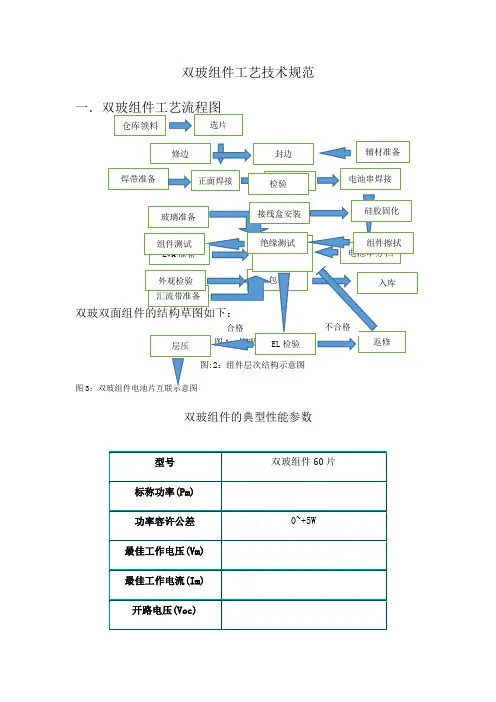
双玻组件工艺技术规范双玻组件的典型性能参数注:温度系数仅供参考,具体数据以所使用电池片的温度系数为准。
二、双玻组件的原材料说明1.电池片晶体硅太阳组件所用的电池片尺寸为156.75mm×156 .75mm的方片,典型电性能参数如下:156.75mm×156.75mm晶体硅太阳方片外型图如下:双面双玻组件由60片156.75mm*156.75mm单晶晶硅电池片串联组成,应确保每个组件所用电池单片的电性能一致性良好,一般组件的电性能是通过单片的串、并联来实现的,每个组件所用到的单片都必须确保它们有高度的电性能一致性,否则将对成品组件的电性能造成较大的影响。
在组件制造时,要对电池片性能进行分选,不允许将电性能差异较大的电池片串联在同一块组件中。
电池片的选购原则一般如下:a)一般选用国际国内知名厂商生产的电池片(每批的电性能一致性较有保障);采用当前先进工艺制作的电池片;b)按实际生产需求挑选合适的具有较高的性价比的厂家单片;c)色泽一致性要求要好d)一批单片要求破损,裂缝,缺角率控制在检验文件规定的范围内。
参考《GB/T12632》单晶体太阳电池总规范,对多晶硅电池来料质量提出要求。
2 钢化玻璃采用低铁钢化绒面玻璃(又称为白玻璃),厚度3.2mm,在太阳电池光谱响应的波长范围内(320-1100nm)透光率达91.5%以上(镀膜玻璃要求透光率在93.5%以上),对于大于1200 nm的红外光有较高的反射率。
此玻璃同时能耐太阳紫外光线的辐射,透光率不下降。
玻璃通过或符合国家标准GB/T 9963和GB 2828-87。
用作光伏组件封装材料的钢化玻璃,对以下几点性能有较高的要求a)抗机械冲击强度b)表面透光性c)弯曲度d)外观3. EVA晶体硅太阳电池封材料是EVA,它是乙烯与醋酸乙烯脂的共聚物,化学式结构如下(CH2—CH2)—(CH—CH2)|O|O — O — CH2EVA是一种热融胶粘剂,常温下无粘性而具抗粘性,以便操作,经过一定条件热压便发生熔融粘接与交联固化,并变的完全透明,长期的实践证明:它在太阳电池封装与户外使用均获得相当满意的效果。

适用于爱康系列双玻光伏组件For AKCOME Double Glass PV Modules版本编号Version Number:AKC/AKGD/2-RD-201A1修订日期Revision Date :2023-03-13网址URL: 电话TEL:+86400-101-7000地址:江苏省张家港市经济开发区金塘路ADD:Jintang Road,Economic Development Zone.01安全与操作说明Safety Warning and Operation NoticeDANGER OF DEATH FROM ELECTRICAL SHOCK!小心触电!电池组件暴露在阳光下能产生电流。
单个组件的电压小于50VDC,但当组件串联起来时整个电压极高。
为了防止电弧作用,着火及触电的危险,以下内容应被充分理解、遵守。
PV modules can generate electricity upon exposure to light.The voltage of a single module is less than50VDC,but the total voltage can be dangerously high when modules are connected together in series.The following must be fully understood and obeyed when handling the PV modules to avoid risk of arcing,fire and electric shock.在安装、使用和保养光伏系统之前请仔细阅读安装使用手册,并且遵守本手册中的安全防范措施,否则有可能引起人身财产损失。
Carefully read through these installation instructions before installing,operating or maintaining PV system.Failure to follow these instructions may result in bodily injury or damage to property.光伏系统产生的高电压和强电流可能会造成严重的伤害和生命危险。
DOC:EG-IM-20190810-1亿晶半片双面双玻组件安装手册GENERAL INSTALLATION MANUALFor EGING Double glass PV modules with bifacial and half-cell目录ContentsGENERAL INSTALLATION MANUAL (1)1.介绍Introduction (1)2.免责说明Disclaimer (1)3.通则General (1)4.机械安装Mechanical Installation (2)4.1选择位置Select the Location (2)4.2选择倾角Tilt Angle (3)4.3选择支架Selecting the Proper Support Structure and Hardware (3)4.4安装安全Installing Security (4)4.5安装方式Installation (6)4.5.1EG-***P72-HD/BF-DG和EG-***M72-HD/BF-DG组件安装方式 (6)4.5.2EG-***P60-HD/BF-DG和EG-***M60-HD/BF-DG组件安装方式 (8)5.1连接Connection (11)5.2接地Grounding (12)5.3电气安全Electrical Safety (12)6.维护Maintenance (13)1.介绍Introduction☆非常感谢您选择常州亿晶光电科技有限公司的半片双面双玻光伏组件(以下简称“组件”)。
Thank you for choosing the Double glass PV modules with bifacial and half-cell of Changzhou EGing Photovoltaic Technology Co.,Ltd.(Hereinafter referred"modules")☆本安装手册提供了亿晶组件的安装和安全使用信息。
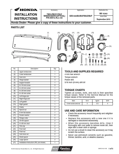
Issue DateINSTALLATION INSTRUCTIONSPublication No.Honda Dealer: Please give a copy of these instructions to your customer.© 2015 American Honda Motor Co., Inc - All Rights Reserved.0SR72-HL4-100Application Accessory PARTS LISTTWO-PIECE POLY WINDSCREEN (OPTICAL)P/N 0SR72-HL4-100SXS1000M3/M3P/M5D/M5PMII 15262September 2015TOOLS AND SUPPLIES REQUIRED4 mm hex wrench Torque wrench Power drill5/16 inch (8 mm) drill bitTORQUE CHARTSTighten all screws, bolts, and nuts to their specified torque values. Refer to the Service Manual for the torque values of the removed parts.ItemN·m kgf·m lbf·ft 6 mm screw and nut50.54USE AND CARE INFORMATION• Check the accessory mount frequently and retighten if necessary.• Replace this accessory with a new one if it is damaged or discolored excessively.• When this accessory becomes dirty, rinse it thoroughly with cool water to remove loose dirt, then wipe with a clean cloth or sponge.• Do not use a brush to clean this accessory as it may scratch the surface.• Never use petroleum solvents such as gasoline, thinner, benzine, acid, or alkaline cleaners.No.DescriptionQty (1)Upper windscreen 1(2)Lower windscreen 1(3)Cam lock 5(4)Hinge bracket 3(5)Support bracket 1(6) 6 x 16 mm screw 9(7) 6 x 20 mm screw 1(8) 6 x 25 mm screw 2(9) 6 x 30 mm screw 3(10)Left hinge arm 1(11)Right hinge arm 1(12)Left gasket 1(13)Right gasket 1(14)Clamp 2(15)Nylock nut 2(16) 6 mm flat washer 1(17)Fender washer 2(18)Flange collar 5(19)25 mm spacer 2(20) 6 x 85 mm stud 2(21)Trim clip 2(22)Push dart 4(23)Push nut 4(24)Cam lever set 2(25)Small spacer 1(26)Large spacer2(27)Installation Instruction URL (not shown)1(1)(2)(10)(11)(12)(13)(16)(17)(18)(19)(26)(5)(14)(25)(21)(20)(9)(8)(23)(6)(7)(22)(3)(4)(24)(15)© 2015 American Honda Motor Co., Inc - All Rights Reserved.0SR72-HL4-100INSTALLATION NOTE:• If installing a complete cab, install this accessory before installing the roof and door kits.• Remove and discard the rubber shipping band from the cam lock before installation of this accessory.SHIPPING BAND (DISCARD)(1. Install two cam locks to the lower windscreen usingone 6 x 25 mm screw and spacer per cam lock.• Screws must be threaded into the hole in the base ofthe clamp as shown.CAM LOCK6 x 25 mm SCREWSPACERGROMMET2. O pen the clamps on boths sides of the lowerwindscreen.3. Place the lower windscreen onto the vehicle frameand seat the bottom edge onto the front hood.A-PILLARWINDSCREEN4. Install the support bracket to the inside of the lowerwindscreen using one 6 x 20 mm screw, one washer,and one small spacer.SUPPORT BRACKETWASHER6 x 20 mm SCREW 5. Using the windscreen support bracket as a template,make a mark on the top of the instrument panel through both holes in the support bracket.6. Remove the lower windscreen and drill holesthrough the marks on the instrument panel with a 5/16 inch (8 mm) drill bit.7A. Place the Left and Right gaskets over the bottomcorners of the lower windscreen, lining up the holes in the gasket and the windscreen.7B. (CAB ONLY): If installing the windscreen as part ofa hard cab system, carefully cut out the indented area of each gasket before installing it to the windscreen.GASKET (LEFT SHOWN)© 2015 American Honda Motor Co., Inc - All Rights Reserved.0SR72-HL4-1008. Install the gaskets to the windscreen using two pushdarts and push nuts per side, as shown.PUSH NUTPUSH DARTGASKET(LEFT SHOWN)9. Reinstall the lower windscreen.Secure the lower windscreen to the instrument panel by placing trim clips through the windscreen bracketand into the holes.TRIM CLIP10. Align the cam locks around the cab A-pillars andsnap the arms closed. Do this on both sides.11. Adjust clamp tension by rotating the threaded armclockwise to tighten, counter-clockwise to loosen.THREADED ARMINSTALLATION - UPPER WINDSCREEN12. Insert two 6 x 16 mm screws into the holes in thehinge bracket and then install them into the base of the cam lock as shown.13. Insert one 6 x 16 mm screw through the hole in thecam lock and then intall it into the hinge bracket asshown.6 x 16 mmSCREWCAM LOCK6 x 16 mm SCREWHINGE BRACKET14. Repeat Steps 12 and 13 for the remaining twohinges and clamps.15. Install a hinge/cam lock assembly into each grommetusing one 6 x 30 mm screw and flange collar, noting the orientation of the hinge/clamp assembly as shown.6 x 30 mm SCREWGROMMETFLANGE COLLARHINGE/CAM LOCK© 2015 American Honda Motor Co., Inc - All Rights Reserved.0SR72-HL4-10016. Insert a lock nut into the the hinge arm bracket asshown.Insert a 6 x 30 mm screw through the hole in the left hinge arm and install it hand-tight into the lock nut. The hinge arm must rotate freely on the bracket.Repeat this process for the right hinge arm.HINGE ARM BRACKET6 x 30 mm SCREWLEFT HINGE ARMLOCK NUT17. Place the upper windscreen onto the cab frame withthe bottom edge overlapping the top edge of the lower windscreen, and then close the cam locks.• Both windscreen sections should be touching each other along the entire overlapping edge.UPPERWINDSCREENLOWERWINDSCREEN• To ensure proper fitment, close the cam locks oncethe gap between the edge of the windscreen and the A-pillars is even along the entire length of the frame.• Approximate angle of the upper cam locks shown.18. Orient a clamp around the A-pillar just above thelower windscreen as shown and loosely install it using one 6 x 20 mm screw.• Do not tighten the bolt yet to allow for clamp position adjustments.6 x 20 mm SCREWCLAMP19. Line up the clamp adjacent to the top of the hingearm and place a large spacer between both components as shown.Thread a stud through the hinge arm and the large spacer into the clamp as shown.Slide a spacer over the end of the stud and into the hinge arm slot as shown.STUDSPACERLARGE SPACERHINGE ARM20. Install a washer and cam lever over the end of thestud as shown. Place the washer on first, then slide on the plastic base and thread on the cam lever.WASHERSTUD CAM LEVERS U21. Repeat Steps 18 through 21 on the right side.CLAMPPLASTIC BASE© 2015 American Honda Motor Co., Inc - All Rights Reserved.0SR72-HL4-100• The overlapping edge between both the upper and lower sections of the windscreen should fit together as shown.22. To open the “folding” windscreen, loosen the camlever handles and push the upper windscreen forward. When the windscreen reaches the desired opening angle, tighten both cam lever handles.。
Contents1 × Enclosure1 × Central Support Plate1 × Cover Plate1 × Dust Cover1 × Trim Bezel6 × Silicone Grommets1 × Hardware PackInstallation Needs•#1 Phillips screwdriver •Drywall saw •Tape measure •Level •¼" flathead screwdriver • Electric drill and ¼" bit Optional Accessories and Hardware • Drywall screws • Electrical box and low voltage ring for adding terminations to cutouts • Compact WattBox (sold separately)Danger: This equipment must be installed and assembled by qualified service personnel in accordance with local building codes. Contact a suitable contractor if necessary.Caution: Before beginning, carefully plan locations, accounting for electrical, ductwork, plumbing or other obstacles that may interfere with installation of the box, equipment, or wiring. Note: Use only standard-size cover plates on boxes and rings installed in the Strong VersaBox. Mid- and jumbo-size plates will not fit.InstallationRemove the cover plate by pulling the finger openings on one side of the cover to pop it loose.Open any knockouts in the VersaBox Pro that will beused for wiring.Drywall Mounting with DogsLocate two studs. Use the cutout template to mark the wall, centered between the studs. Use a level to align it correctly.Cut the opening using a drywall saw. Test fit the box, and clean up the opening as needed.Thread the wiring and cabling through the knockouts, then insert the enclosure.Use a #1 Phillips screwdriver to tighten the dog screws as illustrated. All four dogs must be engaged with the drywall to mount the box securely.Secure the trim bezel with 8 screws on the inside of the enclosure.Pro Tip: If any of the four dogs do not extend correctly due to stud clearance, insert a screw through the side of the box into the adjacent stud. Refer to Stud Mounting with Lag Bolts, below. Stud Mounting with Lag Bolts Pro Tip: For new construction work, account for the drywall thickness when installing. If the studs are wider than 16" apart, or if you are mounting vertically, install using dogs once the drywall is finished. See the Drywall Mounting with Dogs section above for details. If this is a retrofit job, locate two studs. Use the cutout template to mark the wall, centered between the studs. Use a level to align it correctly. Cut the opening using a drywall saw. Test fit the box, and clean up the opening as needed.Remove the center support plate from the VersaBox. Thread the wiring and cabling through the knockouts. Insert the enclosure.Remove the plugs from the mounting holes you wish to use (right). Drill ¼" pilot holes and drive the lag bolts to secure the VersaBox.If this is new construction , insert the dust cover to protect the inside of the VersaBox Pro from the drywall install. Once drywall is installed, remove the dust cover.Secure the trim bezel with 8 screws on the inside of the enclosure.Installing EquipmentWarning: Total equipment weight stored in this enclosure must not exceed 15 pounds.The central support plate provides a variety of configuration options. For configuration examples and ideas, see the VersaBox Pro product page at .Knockouts & ModulesThe knockouts at the top and bottom can be usedfor low voltage rings or for outlet boxes. Any outletbox used must be an old-work, residential-gradebox with integrated work supports to allow forsecure mounting.Wherever you remove a cable/wire entry cover,insert a silicone grommet into the hole. When usingthese for wire access, slit each grommet down themiddle in a “+” shape. When using these for conduit,cut the grommet to the exact size and shape of theconduit for a tight seal.The back wall of the VersaBox Pro has holesand knockouts stamped into it on 6" centers forstructured-can module installation. Use a ¼" drill bit to widen the knockout stamps as needed. Adjusting the Platform Standoffs and Central Support PlateSections of the central support plate can betrimmed with tin snips for customized mountingoptions.There are two sets of standoff clips to mountthe support plate. You can also adjust each setof standoff clips toward the front or rear of theVersaBox Pro. Do do so, remove the platformstandoffs by inserting a ¼” flathead screwdriverinto the gap between the standoff and case.Twist the screwdriver and pry outward toremove each standoff.Rotate the standoff 180° to change the clearance of the central support plate.Press the standoff in until it snaps into place.In addition, the standoffs have two clips to hold the centralsupport plate: you can clip it toward the outside (left) ortoward the inside (right).Finally, the central support plate can be inserted so that itcurves toward the front of the enclosure, or recesses to therear. Between the standoff orientation, the two clipping options, and the reversible support plate, this provides multiple depth options, up to being flush with the front of the enclosure.Technical SupportFor chat and telephone, visit https:///s/contactsupport•Email:***********************Visit /technician for discussions, instructional videos, news, and more.Warranty and Legal NoticesFind details of the product’s Limited Warranty and other resources such as regulatory notices and patent and safety information, at at /legal or request a paper copy from Customer Service at 866.424.4489.Copyright ©2021, Snap One, LLC. All rights reserved. Snap One and its respective logos are registered trademarks or trademarks of Snap One, LLC (formerly known as Wirepath Home Systems, LLC), in the United States and/or other countries. Strong, WattBox, and Wirepath are also registered trademarks or trademarks of Snap One, LLC. Other names and brands may be claimed as the property of their respective owners. Snap One makes no claim that the information contained herein covers all installation scenarios and contingencies, or product use risks. Information within this specification subject to change without notice.211129-1610Part # 200-SM-RBX-PRO-20-BLK-BInstalling a Compact WattBoxRemove the bottom panel by unscrewing the four pre-installed screws. Insert the compact WattBox, and replace the four screws to secure it. For further installation information, see the WattBox product manual.Reattaching the CoverTo slide the cover on, seat the hooks on one side first, and push the other side in until it clicks.(Factory Position)。
玻璃安装作业指导书适用于一般工业与民用建筑工程的平板、吸热、热反射、中空、夹层、夹丝、磨砂、钢化、彩色、压花玻璃及懊恼砖等玻璃工程。
钢、木框扇玻璃及玻璃砖安装一、施工准备1、材料⑴玻璃或玻璃砖:品种、规格按设计要求选用。
⑵油灰:可在市场上买成品,•也可参照下列重量配合比自行配制,蚬灰粉:桐油:水=100:27.5:2.5。
先把水和部分桐油加进蚬灰内,用电动捶椿捣,边捣边拌和,以后再把其余桐油逐渐加入,用电锤椿捣4小时成桐油灰。
鉴别油灰的技术性能可参照下列指标:①、外观:为灰黄色稠塑性固体膏状物,手感柔软,有拉力、支撑力,有桐油香味,粘性很强等特征。
②、硬化:油灰涂抹后,在常温下5昼夜硬化。
③、用于钢门窗玻璃的油灰,应有防锈性。
⑶其他材料:红丹、玻璃钉、钢丝卡子、橡皮垫、木条、煤油。
2、作业条件⑴玻璃应在内外门窗经框扇校正和五金安装后,在涂刷最后一遍涂料前进行安装。
玻璃隔断的玻璃安装,参照上述要求进行。
⑵钢门窗在正式安装玻璃前,要检查是否有扭曲,应进行修理和排选后,再安装玻璃。
⑶玻璃安装前,应按设计要求尺寸,预先集中裁制,其长宽各应缩小遮盖玻璃槽(子口)宽度的1/4。
•并按不同规格和安装顺序放在安全处备用。
对于集中加工后进场的半成品,应有针对性的选择几樘进行试安装,提前核实来料的尺寸,留量是否合适(上下余量3MM,两边余量4MM),边缘不得有斜曲或缺角等情兑。
必要时应作再加工处理或更换。
⑷将需要安装的玻璃,按部位分规格、数量分别将裁好的玻璃分送就位。
二、操作工艺1、安装顺序:一般先安外门窗,后安内门窗。
2、木框扇玻璃安装前,应将裁口内的污垢清除干净,•并沿裁口的全长均匀涂抹1~3MM厚的底油灰。
随后把玻璃推铺平整、压实后收净底灰。
四边分别钉上钉子,间距为150~200MM,每边不少于两个钉子,钉完后用手敲玻璃,如响声坚实,说明玻璃安装平实;如响声啪啦啪啦,说明油灰不严,取下玻璃重新安装,然后用油灰填实抹光;如采用木压条固定时,应先涂干性油,并不得将玻璃压得过紧。