
LED驱动器介绍
- 格式:ppt
- 大小:17.45 MB
- 文档页数:72


led驱动工作原理
LED驱动工作原理实际上就是将电源的直流电转换为适合
LED的电流和电压。
LED(Light Emitting Diode)是一种能够
发光的二极管,它需要特定的电流和电压才能正常工作。
首先,LED驱动器的输入端连接到交流电源或直流电源。
交
流电源通常需要通过整流器将其转换为直流电源。
其次,LED驱动器中含有电源管理电路,用于稳定电源电压,并通过各种保护机制,如过压保护、过流保护、温度保护等,确保LED工作在安全可靠的条件下。
然后,LED驱动器会根据LED的特性将输出的电流和电压进
行调整,以满足LED工作的要求。
通常,驱动器会通过调整PWM(脉冲宽度调制)信号的占空比来控制输出电流的大小。
最后,调整完输出电流和电压后,驱动器会将其输出到LED
的正极和负极,从而使得LED能够正常发光。
总结起来,LED驱动工作原理即是将输入的直流电源转换为
适合LED工作的电流和电压,并通过调整PWM信号来控制
输出电流的大小,从而驱动LED发光。
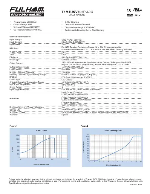
T1M1UNV105P-60GSPECIFICATIONS
Fulham extends a limited warranty to the original purchaserorfirstuserforaperiodof5 years @ Tc 82Cfrom the date of manufacturewhenproperlyinstalled and operated under normal conditions of use. For complete terms and conditions, please refer to the Warranty Center at www.fulham.com. Specifications subject to change without notice
• Programmable LED Driver
• Output Wattage: 60W
• Universal Voltage (120V-277V)
• CC Programmable 250-1050mA
General Specifications Input Voltage Input Current Input Power
NTC Input
• 0-10V D im ming • Compact Case and Terminal
• Output voltage range of 10-57VDC
•
120-277VAC, 50/60 Hz 0.6A@120V, 0.26A@277V 72W Ext. NTC Derating Resistence Range: 1k to 51k Ohm programmable. Default/Recommended Ext. NTC P/N: TSM2A204, SMD0805, Thinking Electronic

# 58014CLS LDC-41 GII DMX LED DRIVERManualV1.0 - December 2017Index2 Safety information3 Optional accessories 3 Introduction4 Measurements 4 Lay-out description 4 Pinning DMX output 4 Installation5 Mounting5 Choosing power supply 5 Connect power supply6 Connect LED fixture 6 Connect DMX7 Status display8 Configuration8 Page 1: DMX addressing 9 Page 2: Channel configuration 9 Page 3: Control configuration 10 Page 4-7: Current configuration 10 Page 8: Test sequence 10 Page 9: Store configuration 10 Page 10: Cancel configuration 10Technical specifications11INDEXOptional accessories 911465 CLS LD serie GII adapter cable XLR3 male to RJ45911468 CLS LD serie GII adapter cable RJ45 to XLR3 female 911366 CLS LDC adaptercable LDC to XLR7 including terminator 911367 CLS LDC adaptercable LDC to SmartConnect system 911368 CLS LD serie adapter cable RJ45 to XLR3 female 113100 CLS LDC-41 connection cable to XLR7 including terminator 113110 CLS LDC-41 connection cable to Luxo 3 RGB 707028 CLS Zense DMX controller + built in 4 amp RGB dimmer 707030 CLS ACX60 DMX controller for max. 60 channels 706995 CLS BT20.24 LED power supply 24VDC 2-VA 85-264VAC 707011 CLS BT45.24 LED power supply 24VDC 45VA 85-264VAC 707012 CLS BT75.24 LED power supply 24VDC 75VA 85-264VAC 707013 CLS BT120.24 LED power supply 24VDC 120VA 85-264VAC 707014 CLS BT240.24 LED power supply 24VDC 240VA 85-264VAC 707018 CLS BT75.48 LED power supply 48VDC 75VA 85-264VAC 707019 CLS BT120.48 LED power supply 48VDC 120VA 85-264VAC 707020 CLS BT240.48 LED power supply 48VDC 240VA 85-264VACAmbiance Max. 40ºBlock access below the work area when maintaining the unitUse a source of AC power that complies to local electricalcodes Disconnect the power supply before installing or maintainingDon’t install in a flammable or explosiveareaWarning!Some surfaces can be hotDo not stare into the LEDDon’t modify or install genuine parts on this product QualifiedtechnicianMake sure all connectors are connected properlyCONTENTSAFETY INFORMATIONMEASUREMENTSThe CLS LDC-41 is a DMX controllable LED dimmer, which has 4 current controlled DC outputs. The current can be adjusted in steps of 50mA from 350 to 1000mA per channel. Each channel can drive 2 to 12 LEDs in series. Equipped with 4 channels the LDC-41 is suitable for controlling the newest generation of LED fixtures, RGBW or RGBA. This makes it possible to connect 2 to 12 RGB or even RGB(A/W) fixtures on one driver. Unique is the DIN-rail mounting possibility of the new and small housing. The LDC-41 is equipped with a user friendly menu structure, which offers some smart solutions for installers to test and set up an installation.Output connectorPower input connector DisplayUp button DMX input/outputDMX input/outputMenu buttonDown buttonLAY-OUT DESCRIPTIONPINNING DMX OUTPUT22345665432432341.G ND2.D-3.D+1.G ND2.D-3.D+DMX OUT DMX IN DMX OUTDMX INXLR3XLR54. N/C5. N/CINTRODUCTIONPIN COLOUR FUNCTION 1 Orange/white DMX data +2 Orange DMX data -3 Green/White Not connected 4 Blue Not connected 5 Blue/White Not connected 6 Green Not connected 7 Brown/White DMX Common 8BrownDMX CommonThis section describes in general terms how to install the LDC-41. How to setup the menu, data link and how to connect it to a fixture.MountingThe LDC-41 has a unique feature, it is designed to be installed on a DIN-rail. Now it is possible to install the LDC-41 directly next to the power supplies which are also suitable for DIN-rail mounting.This helps to keep your installation work modular and fault proof.Choosing power supplyUse a power supply with an output voltage which is compatible with the LED fixtures you are using. To choose the correct power supply use the two tables below.Keep in mind that the table is determined with an equal load on all 4 outputs. For example 6 LEDs means 6 LEDs on all 4 outputs.* The number of fixtures is divided in 3 catagories, total = total amount of fixtures on the driver, minimum = miminum amount of fixtures per channel, maximum = maximum amount of fixtures perchannel. With RGB (A/W) fixtures total is not used because per fixture all channels are used.INSTALLATIONLocate the “INPUT” connection block at the top of the LDC-41, check information sticker on the side of the LDC-41. Connect the positive (+) output of the power supply to positive (+) power input of the LDC-41. Connect the negative (-) output of the power supply to the negative (-) power input of the LDC-41.Connect LED fixtureLocate the “OUTPUT” connection block at the top of the LDC-41, check information sticker on the side of the LDC-41. Connect the fixture’s RED positive (+ or anode) to Channel 1 (R) of the LDC-41. Repeat this step for the Green, Blue and/or White/Amber colour.If all colours have separate negative (- or cathode) wires then tie them together and connect to negative (-) power input of the LDC-41. If all colours have a combined negative (- or cathode) wire, connect to negative (-) power input of the LDC-41.The LDC-41 can also control single colour LED fixture’s. You can use the 4 output to create different zone’s that can be controlled separately or simultaneously.24-48 VDCCONNECT POWER SUPPLYHold Menu button for 3 seconds to store or cancel Use Up/Down buttonPage 1: DMX addressingIn this page you can adjust the DMX address of the LDC-41. Use the up and down button to adjust the value. Hold down the up or down button to scroll fast. When DMX address is selected press the menu button to return to the main menu.Default DMX address: 1buttonPage 2: Channel configurationIn this page you can adjust the Channel configuration of the LDC-41. With the channel configuration you can configure how the outputs respond to the DMX channels. Use the up and down button to adjust the value. When Channel configuration is selected press the menu button to return to the main menu. DMX channel n is the DMX address of the LDC-41.Option 1: All 4 outputs respond to DMX channel n. This option can be used for single colour applications.Option 2: The first 2 channels respond to DMX channel n and last 2 channels respond to DMX channel n+1. This can be used for 2 zones single colour applications.Option 3: The first 3 channels respond to separate DMX channels n and last 2 channels respond to DMX channel n+1. This can be used for 3 zones single colour applications.Option 4: All 4 outputs respond to separate DMX channels. This option can be used for RGB(A/W) applications.Default Channel option: 4buttonOutput DMX channelsn n+1 n+2 n+31 √ - - -2 √ - - -3 √ - - -4 √ - - -Output DMX channelsn n+1 n+2 n+31 √ - - -2 √ - - -3 - √ - -4 - √ - -Output DMX channelsn n+1 n+2 n+31 √ - - -2 - √ - -3 - - √ -4 - - √ -Output DMX channelsn n+1 n+2 n+31 √ - - -2 - √ - -3 - - √ -4- - - √Page 3: Control configurationIn this page you can adjust the Control of theLDC-41. By enabling the Control configurationthe LDC-41 will use a master dimmer channel.With the master dimmer channel the light can bedimmed without changing the colour channels.The master dimmer channel will be added after thelast DMX channel used to control the outputs ofthe LDC-41. Use the up and down button to adjustthe value. When Channel configuration is selectedpress the menu button to return to the main menu.Default Control configuration: Disabled (0)buttonChannel Option Control configurationDisabled (0)Enabled (1)1 - DMX channel n+12 - DMX channel n+23 - DMX channel n+4Page 4-7: Current configurationTo adjust the current of an output channel enterthe corresponding page and change the value. Thecurrent can be adjusted from 350 – 1000mA insteps of 50mA. To return to the main menu pressthe menu button.buttonPage 8: Test sequenceEntering this page will result in a test sequence onthe outputs of the LDC-41. This enables the user totest the connections without the need of an DMXcontroller. To end the test sequence and return tothe main menu press the menu button.Page 9: Store configurationAfter all changes are made the setting need to bestored before they become active. To store thesettings go to the store page and press and holdthe menu button for 3 seconds. The settings arestored and you will return to the status display.Hold the Menu buttonfor 3 seconds to storePage 10: Cancel configurationWhen you have made changes but you don’t wantto store them you can leave the configurationmenu without storing them. To cancel the settingsgo to the cancel page and press and hold the menubutton for 3 seconds. The settings are not storedand you will return to the status display.Default Current configuration: 700mA for each channelHold the Menu buttonfor 3 seconds to cancelSpefificationsPower Supply: 24-48VDCIdle Power: Max. 0,5 WattPower consumption: Max. 185 WattLEDs in serie: 2-12 per channelOutput: 4 channelsOutput voltage: 22-46VDCOutput current: 350-1000 mAFuse: no fuseDMX protocol: DMX512/1990Data in/out: RJ45Housing: PlasticIP rating: IP40Measurements: 110 x 25 x 125 mm (hxwxd)Mounting: DIN-railWeight: 210 grWorking temperature: -10 °C to +60 °CTECHNICAL2018 CLS-LED BV. All rights reserved. Information subject to change without notice, CLS-LED BV and all affiliated companies disclaim liability for injury, damage direct or indirect loss, consequential or economic loss or any other loss occasioned by the use of, inability to use or reliance on the information contained in this manual. No part of this manual may be reproduced, in any form or by any means, without permission in writing from CLS-LED BV. Other legal information can be found in our General conditions, found on the back ofyour CLS-LED BV invoice, inside the CLS catalogue or on our website /General-Terms.pdfLIST OF SYMBOLSMultiple connectionDaisychain connectivityInstallation depthIn centimetersSwivelFixture is horizontally rotatable,indicated in degreesSwivelFixture is vertically rotatable,indicated in degreesInstallation sizeIn centimetersApplication areaIndoor or outdoorApplication areaFloor, wall or ceilingProtection classOne, two or threeCable lengthMaximum cable attachedto the fixture in centimetersLifespanOf the light source in hoursDriverInclusive or exclusiveInternal or externalPressureMaximum pressure on thefixture in kg/cmWeightIn grams/kilogramsCurveMinimal bending curvein centimetersLED pitchPitch between the LEDsin millimetersPower supplyIn VDC, VAC or milliAmperePower consumptionIn VA or WattIP valueIngress Protection classifies thedegrees of protection provided againstthe intrusion of the productCutting lengthIndicated by the cuttingmarksLEDsKind of LED used in thefixtureLensesAvailble lenses,indicated in degreesPlug & playEasy connection using theSmartConnect systemWhite colour temperatureIn di erent Kelvin values;Cold white, neutral white, warmwhite or extra warm whiteColourAvailable colours;Amber, blue, red or greenColour changingRGB, RGB-W, RGB-A,AWB or Tunable WhiteDMX inputFixture works on DMX512protocolMagno dimmingAccurate dimming from100 - 1% by using a magnetDynamic ControlDynamic Power Control orDynamic Temperature ControlCombined productCompose your own fixtureWarranty3 or 5 years warranty onthe productEnergy labelConformité EuropéenneCE marking for free marketabilityof industrial goods within the EUDimmable1-10 Volt, Phase, individual,DMX dimmable or DALIDRIVER DRIVERRetail & Food LED modulesClothing, furniture, kitchens, jewellery,shoes, bread, meat,fish & vegetables & fruit.LightsourceEquipped with a CLS, Citizen or a XicatoLED moduleBluetooth controlledBy Casambi。

三色led筒灯驱动器的原理
三色LED筒灯驱动器的原理基本上是通过控制电流和电压来实现对三色LED灯的亮度和颜色的控制。
下面是一个简单的三色LED筒灯驱动器的工作原理:
1. 选择合适的供电电源:LED筒灯通常需要脉冲直流(PWM)供电,因此选择一个能够提供稳定的直流电源的电池或电源适配器。
2. 控制电流:为了控制LED的亮度,可以通过电源电压和电阻来控制电流。
选择合适的电阻来限制LED电流的大小,以避免电流过大导致LED损坏。
3. 连接三色LED:将红、绿、蓝三个LED连接在一起,形成一个三色LED灯组,每个LED连接一个独立的控制信号线。
4. 控制信号:使用微控制器(MCU)或其他控制器生成来控制三色LED的亮度和颜色的控制信号。
可以通过改变控制信号的频率来调节LED的亮度,通过控制信号的占空比来调节LED的颜色。
5. PWM调制:使用脉冲宽度调制技术(PWM)来控制LED的亮度。
通过改变控制信号的占空比,即脉冲的高电平时间与周期的比例,来调节LED的亮度。
6. 颜色混合:通过改变控制信号的幅度和相位差来调节红、绿、蓝三个LED的亮度,从而实现不同颜色的混合。
7. 保护电路:为了防止过电流、过压和短路等情况对LED的损害,可以添加保护电路,如过流保护、过压保护和短路保护等。
总之,三色LED筒灯驱动器通过控制电流和电压,以及控制信号的频率、占空比和相位差等参数,实现对LED的亮度和颜色的精确控制。