Arduino_Mega_2560使用手册
- 格式:doc
- 大小:364.00 KB
- 文档页数:13
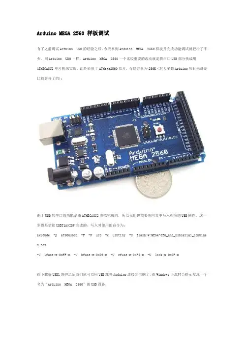
Arduino MEGA 2560 样板调试有了之前调试Arduino UNO的经验之后,今天拿到Arduino MEGA 2560样板并完成功能调试就轻松了不少。
同Arduino UNO一样,Arduino MEGA 2560一个比较重要的改动就是将串口USB部分换成用ATMEGA8U2单片机来实现,此外采用了ATMega2560芯片,存储容量为256K(对大多数Arduino项目来讲是比较奢侈了的):由于USB转串口的功能是由ATMEGA8U2虚拟完成的,所以我们也需要先向其中写入相应的USB固件,这一步骤是借助USBTinyISP完成的,写入时使用的命令为:avrdude -p at90usb82 -F -P usb -c usbtiny -U flash:w:MEGA-dfu_and_usbserial_combined.hex-U lfuse:w:0xFF:m -U hfuse:w:0xD9:m -U efuse:w:0xF4:m -U lock:w:0x0F:m在下载好USBl固件之后我们就可以用USB线将Arduino连接到电脑了,在Windows下此时会提示发现一个名为“Ardu ino MEGA 2560”的USB设备:随后Windows会打开“找到新的硬件向导”对话框,选择其中的“否,暂时不”后单击“下一步”按钮:在接下来出现的对话框中选择“从列表或指定位置安装(高级)”项后单击“下一步”按钮:随后我们需要指定Arduino 0021安装目录下的drivers目录来进行驱动程序的安装:如果一切正常,Windows会开始为Arduino MEGA 2560安装相应的驱动程序:正功安装后的提示界面:此时我们就可以在Windows的设备管理器中找到相应的Arduino MEGA 2560设备了:接下来就可以向ATMega2560芯片中烧入Arduino的Bootloader了,这一过程同样可以借助USBTinyISP来完成。
来源:Arduino Mega2560简介Arduino Mega2560也是采用USB接口的核心电路板,它最大的特点就是具有多达54路数字输入输出,特别适合需要大量IO接口的设计。
Mega2560的处理器核心是ATmega2560,同时具有54路数字输入/输出口(其中16路可作为PWM输出),16路模拟输入,4路UART接口,一个16MHz晶体振荡器,一个USB口,一个电源插座,一个ICSP header 和一个复位按钮。
Arduino Mega2560也能兼容为Arduino UNO设计的扩展板。
Arduino Mega2560已经发布到第三版,与前两版相比有以下新的特点:在AREF处增加了两个管脚SDA和SCL,支持I2C接口;增加IOREF和一个预留管脚,将来扩展板将能兼容5V和3.3V核心板。
改进了复位电路设计。
USB接口芯片由ATmega16U2替代了ATmega8U2。
概要▪处理器 ATmega2560▪工作电压 5V▪输入电压(推荐) 7-12V▪输入电压(范围) 6-20V▪数字IO脚 54 (其中16路作为PWM输出)▪模拟输入脚 16▪IO脚直流电流 40 mA▪ 3.3V脚直流电流 50 mA▪Flash Memory 256 KB (ATmega328,其中8 KB 用于bootloader)▪SRAM 8 KB▪EEPROM 4 KB▪工作时钟 16 MHz电路图和PCB▪电路图▪硬件设计文件(Eagle文件)▪引脚图电源Arduino Mega2560可以通过3种方式供电,而且能自动选择供电方式▪外部直流电源通过电源插座供电。
▪电池连接电源连接器的GND和VIN引脚。
▪USB接口直接供电。
电源引脚说明▪VIN --- 当外部直流电源接入电源插座时,可以通过VIN向外部供电;也可以通过此引脚向Mega2560直接供电;VIN有电时将忽略从USB或者其他引脚接入的电源。
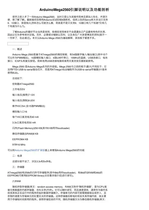
ArduinoMega2560引脚说明以及功能剖析 很早之前⼊⼿了⼀块Arduino Mega2560,当时只是认为其操作简单且更加⼈性化,开源⽅便,想了解了解。
最新搞项⽬想⽤Arduino试试控制8路舵机,但⽹上找的Servo库⼤多说只⽀持9,10接⼝,很是恼⽕(资料怎么写就怎么搬,到底是不是只⽀持9,10接⼝有⼏个知道?⼜有⼏个知道为什么?)。
了解Arduino的最好平台当然是官⽹,我相信官⽹肯定不会遗漏⾃⼰产品最有特⾊的东西,因此以它为参考绝对没错。
另外,必要部分辅助以百科,以及各位⼴⼤亲爱博友的资料(就不⼀⼀列举了,在此谢过)。
本⽂以Arduino Mega 2560为基础解释,其他板⼦都差不多。
⼀:概述 Arduino Mega 2560是基于ATmega2560的微控制板,有54路数字输⼊/输出端⼝(其中15个可以作为PWM输出),16路模拟输⼊端⼝,4路UART串⼝,16MHz的晶振,USB连接⼝,电池接⼝,ICSP头和复位按钮。
简单地⽤USB连接电脑或者⽤交直流变压器就能使⽤。
Mega 2560 是Arduino Mega系列的升级版。
Mega 2560与之前的板⼦(最⼤)不同在于:它没⽤FTDI USB-to-serial驱动芯⽚,⽽是⽤ATmega16U2编程作为USB-to-serial传输器(V1版本使⽤8U2)。
总结如下: 控制器ATmega2560 ⼯作电压5V 输⼊电压(推荐)7-12V 输⼊电压(限制)6-20V 数字I/0⼝54 (含15路PWM输出) 模拟输⼊⼝16 每个I/0⼝直流电流40 mA 3.3v⼝直流电流50 mA 闪存(Flash Memory)256 KB(其中8 KB⽤作bootloader) 静态存储器(SRAM)8 KB EEPROM4 KB 时钟16 MHz可以将Arduino Mega2560的扩展版插上来增强Arduino Mega2560的功能 ⼆:电源 这部分就不说了,涉及3.3v和5v供电。
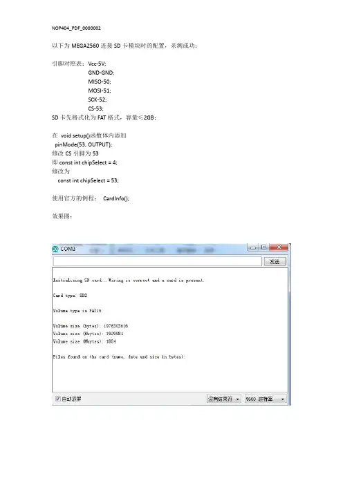
以下为MEGA2560连接SD卡模块时的配置,亲测成功:引脚对照表:Vcc-5V;GND-GND;MISO-50;MOSI-51;SCK-52;CS-53;SD卡先格式化为FAT格式,容量≤2GB;在void setup()函数体内添加pinMode(53,OUTPUT);修改CS引脚为53即const int chipSelect=4;修改为const int chipSelect=53;使用官方的例程:CardInfo();效果图:附件:修改后的源代码/*SD card testThis example shows how use the utility libraries on which the'SD library is based in order to get info about your SD card.Very useful for testing a card when you're not sure whether its working or not. The circuit:*SD card attached to SPI bus as follows:**MOSI-pin11on Arduino Uno/Duemilanove/Diecimila**MISO-pin12on Arduino Uno/Duemilanove/Diecimila**CLK-pin13on Arduino Uno/Duemilanove/Diecimila**CS-depends on your SD card shield or module.Pin4used here for consistency with other Arduino examples created28Mar2011by Limor Friedmodified9Apr2012by Tom Igoe*///include the SD library:#include<SPI.h>#include<SD.h>//set up variables using the SD utility library functions:Sd2Card card;SdVolume volume;SdFile root;//change this to match your SD shield or module;//Arduino Ethernet shield:pin4//Adafruit SD shields and modules:pin10//Sparkfun SD shield:pin8const int chipSelect=53;void setup(){//Open serial communications and wait for port to open:Serial.begin(9600);while(!Serial){;//wait for serial port to connect.Needed for native USB port only}pinMode(53,OUTPUT);Serial.print("\nInitializing SD card...");//we'll use the initialization code from the utility libraries//since we're just testing if the card is working!if(!card.init(SPI_HALF_SPEED,chipSelect)){Serial.println("initialization failed.Things to check:");Serial.println("*is a card inserted?");Serial.println("*is your wiring correct?");Serial.println("*did you change the chipSelect pin to match your shield or module?");return;}else{Serial.println("Wiring is correct and a card is present.");}//print the type of cardSerial.print("\nCard type:");switch(card.type()){case SD_CARD_TYPE_SD1:Serial.println("SD1");break;case SD_CARD_TYPE_SD2:Serial.println("SD2");break;case SD_CARD_TYPE_SDHC:Serial.println("SDHC");break;default:Serial.println("Unknown");}//Now we will try to open the'volume'/'partition'-it should be FAT16or FAT32if(!volume.init(card)){Serial.println("Could not find FAT16/FAT32partition.\nMake sure you've formatted the card");return;}//print the type and size of the first FAT-type volumeuint32_t volumesize;Serial.print("\nVolume type is FAT");Serial.println(volume.fatType(),DEC);Serial.println();volumesize=volume.blocksPerCluster();//clusters are collections of blocks volumesize*=volume.clusterCount();//we'll have a lot of clusters volumesize*=512;//SD card blocks are always512bytes Serial.print("Volume size(bytes):");Serial.println(volumesize);Serial.print("Volume size(Kbytes):");volumesize/=1024;Serial.println(volumesize);Serial.print("Volume size(Mbytes):");volumesize/=1024;Serial.println(volumesize);Serial.println("\nFiles found on the card(name,date and size in bytes):");root.openRoot(volume);//list all files in the card with date and sizeroot.ls(LS_R|LS_DATE|LS_SIZE);}void loop(void){}。
来源:/ Arduino Mega2560简介Arduino Mega2560也是采用USB接口的核心电路板,它最大的特点就是具有多达54路数字输入输出,特别适合需要大量IO接口的设计。
Mega2560的处理器核心是ATmega2560,同时具有54路数字输入/输出口(其中16路可作为PWM输出),16路模拟输入,4路UART接口,一个16MHz晶体振荡器,一个USB口,一个电源插座,一个ICSP header 和一个复位按钮。
Arduino Mega2560也能兼容为Arduino UNO设计的扩展板。
Arduino Mega2560已经发布到第三版,与前两版相比有以下新的特点:在AREF处增加了两个管脚SDA和SCL,支持I2C接口;增加IOREF和一个预留管脚,将来扩展板将能兼容5V和3.3V核心板。
改进了复位电路设计。
USB接口芯片由ATmega16U2替代了ATmega8U2。
概要▪处理器 ATmega2560▪工作电压 5V▪输入电压(推荐) 7-12V▪输入电压(范围) 6-20V▪数字IO脚 54 (其中16路作为PWM输出)▪模拟输入脚 16▪IO脚直流电流 40 mA▪ 3.3V脚直流电流 50 mA▪Flash Memory 256 KB (ATmega328,其中8 KB 用于bootloader)▪SRAM 8 KB▪EEPROM 4 KB▪工作时钟 16 MHz电路图和PCB▪电路图/en/uploads/Main/arduino-mega2560 -schematic.pdf▪硬件设计文件(Eagle文件)/en/uploads/Main/arduino-mega25 60-reference-design.zip▪引脚图/en/Hacking/PinMapping2560电源Arduino Mega2560可以通过3种方式供电,而且能自动选择供电方式▪外部直流电源通过电源插座供电。
来源:Arduino Mega2560简介Arduino Mega2560也是采用USB接口的核心电路板,它最大的特点就是具有多达54路数字输入输出,特别适合需要大量IO接口的设计。
Mega2560的处理器核心是ATmega2560,同时具有54路数字输入/输出口(其中16路可作为PWM输出),16路模拟输入,4路UART接口,一个16MHz晶体振荡器,一个USB口,一个电源插座,一个ICSP header 和一个复位按钮。
Arduino Mega2560也能兼容为Arduino UNO设计的扩展板。
Arduino Mega2560已经发布到第三版,与前两版相比有以下新的特点:在AREF处增加了两个管脚SDA和SCL,支持I2C接口;增加IOREF和一个预留管脚,将来扩展板将能兼容5V和3.3V核心板。
改进了复位电路设计。
USB接口芯片由ATmega16U2替代了ATmega8U2。
概要▪处理器 ATmega2560▪工作电压 5V▪输入电压(推荐) 7-12V▪输入电压(范围) 6-20V▪数字IO脚 54 (其中16路作为PWM输出)▪模拟输入脚 16▪IO脚直流电流 40 mA▪ 3.3V脚直流电流 50 mA▪Flash Memory 256 KB (ATmega328,其中8 KB 用于bootloader)▪SRAM 8 KB▪EEPROM 4 KB▪工作时钟 16 MHz电路图和PCB▪电路图▪硬件设计文件(Eagle文件)▪引脚图电源Arduino Mega2560可以通过3种方式供电,而且能自动选择供电方式▪外部直流电源通过电源插座供电。
▪电池连接电源连接器的GND和VIN引脚。
▪USB接口直接供电。
电源引脚说明▪VIN --- 当外部直流电源接入电源插座时,可以通过VIN向外部供电;也可以通过此引脚向Mega2560直接供电;VIN有电时将忽略从USB或者其他引脚接入的电源。
ArduinoMEGA2560R3Arduino MEGA 2560 R3FeaturesOverviewThe Arduino Mega 2560 is a microcontroller board based on the ATmega2560 (datasheet). It has 54 digital input/output pins (of which 14 can be used as PWM outputs), 16 analog inputs, 4 UARTs (hardware serial ports), a 16 MHz crystal oscillator, a USB connection, a power jack, an ICSP header, and a reset button. It contains everything needed to support the microcontroller; simply connect it to a computer with a USB cable or power it with a AC-to-DC adapter or battery to get started. The Mega is compatible with most shields designed for the Arduino Duemilanove or Diecimila.The Mega 2560 is an update to the Arduino Mega, which it replaces.The Mega2560 differs from all preceding boards in that it does not use the FTDIUSB-to-serial driver chip. Instead, it features the ATmega16U2 (ATmega8U2 in the revision 1 and revision 2 boards) programmed as a USB-to-serial converter. Revision 2 of the Mega2560 board has a resistor pulling the 8U2 HWB line to ground, making it easier to put into DFU mode.Revision 3 of the board has the following new features:1.0 pinout: added SDA and SCL pins that are near to the AREF pin and two other new pins placed near to the RESET pin, the IOREF that allow the shields to adapt to the voltage provided from the board. In future, shields will be compatible both with the board that use the AVR, which operate with 5V and with theArduino Due that operate with 3.3V. The second one is a not connected pin, that is reserved for future purposes.Stronger RESET circuit.Atmega 16U2 replace the 8U2.Schematic, Reference Design & Pin MappingEAGLE files: arduino-mega2560_R3-reference-design.zipSchematic: arduino-mega2560_R3-schematic.pdfPin Mapping: PinMap2560 pageSummaryMicrocontroller ATmega2560Operating Voltage 5VInput Voltage (recommended) 7-12VInput Voltage (limits) 6-20VDigital I/O Pins 54 (of which 15 provide PWM output)Analog Input Pins 16DC Current per I/O Pin 40 mADC Current for 3.3V Pin 50 mAFlash Memory 256 KB of which 8 KB used by bootloaderSRAM 8 KBEEPROM 4 KBClock Speed 16 MHzPowerThe Arduino Mega can be powered via the USB connection or with an external power supply. The power source is selected automatically.External (non-USB) power can come either from an AC-to-DC adapter (wall-wart) or battery. The adapter can be connected by plugging a 2.1mm center-positive plug into the board's power jack. Leads from a battery can be inserted in the Gnd and Vin pin headers of the POWER connector.The board can operate on an external supply of 6 to 20 volts. If supplied with less than 7V, however, the 5V pin may supply less than five volts and the board may be unstable. If using more than 12V, the voltage regulator may overheat and damage the board. The recommended range is 7 to 12 volts.The power pins are as follows:VIN. The input voltage to the Arduino board when it's using an external power source (as opposed to 5 volts from the USB connection or other regulated power source). You can supply voltage through this pin, or, if supplying voltage via the power jack, access it through this pin.5V. This pin outputs a regulated 5V from the regulator on the board. The board can be supplied with power either from the DC power jack (7 - 12V), the USB connector (5V), or the VIN pin of the board (7-12V). Supplying voltage via the 5V or 3.3V pins bypasses the regulator, and can damage your board. We don't advise it.3V3. A 3.3 volt supply generated by the on-board regulator. Maximum current draw is 50 mA.GND. Ground pins.MemoryThe ATmega2560 has 256 KB of flash memory for storing code (of which 8 KB is used for the bootloader), 8 KB of SRAM and 4 KB of EEPROM (which can be read and written with the EEPROM library).Input and OutputEach of the 54 digital pins on the Mega can be used as an input or output, using pinMode(), digitalWrite(), and digitalRead() functions. They operate at 5 volts. Each pin can provide or receive a maximum of 40 mA and has an internal pull-up resistor(disconnected by default) of 20-50 kOhms. In addition, some pins have specialized functions:Serial: 0 (RX) and 1 (TX); Serial 1: 19 (RX) and 18 (TX); Serial 2: 17 (RX) and 16 (TX); Serial 3: 15 (RX) and 14 (TX). Used to receive (RX) and transmit (TX) TTL serial data. Pins 0 and 1 are also connected to the corresponding pins of the ATmega16U2 USB-to-TTL Serial chip.External Interrupts: 2 (interrupt 0), 3 (interrupt 1), 18 (interrupt 5), 19 (interrupt 4), 20 (interrupt 3), and 21 (interrupt 2). These pins can be configured to trigger an interrupt on a low value, a rising or falling edge, or a change in value. See the attachInterrupt() function for details.PWM: 2 to 13 and 44 to 46. Provide 8-bit PWM output with the analogWrite() function.SPI: 50 (MISO), 51 (MOSI), 52 (SCK), 53 (SS). These pins support SPI communication using the SPI library. The SPI pins are also broken out on the ICSP header, which is physically compatible with the Uno, Duemilanove and Diecimila.LED: 13. There is a built-in LED connected to digital pin 13. When the pin is HIGH value, the LED is on, when the pin is LOW, it's off.TWI: 20 (SDA) and 21 (SCL). Support TWI communication using the Wire library. Note that these pins are not in the same location as the TWI pins on the Duemilanove or Diecimila.The Mega2560 has 16 analog inputs, each of which provide 10 bits of resolution (i.e. 1024 different values). By default they measure from ground to 5 volts, though is it possible to change the upper end of their range using the AREF pin and analogReference() function.There are a couple of other pins on the board:AREF. Reference voltage for the analog inputs. Used with analogReference().Reset. Bring this line LOW to reset the microcontroller. Typically used to add a reset button to shields which block the one on the board.CommunicationThe Arduino Mega2560 has a number of facilities for communicating with a computer, another Arduino, or other microcontrollers. The ATmega2560 provides four hardware UARTs for TTL (5V) serial communication. An ATmega16U2 (ATmega 8U2 on the revision 1 and revision 2 boards) on the board channels one of these over USB and provides a virtual com port to software on the computer (Windows machines will need a .inf file, but OSX and Linux machines will recognize the board as a COM port automatically. The Arduino software includes a serial monitor which allows simple textual data to be sent to and from the board. The RX and TX LEDs on the board will flash when data is being transmitted via theATmega8U2/ATmega16U2 chip and USB connection to the computer (but not for serial communication on pins 0 and 1).On Rev1 boards: connecting the solder jumper on the back of the board (near the map of Italy) and then resetting the 8U2.On Rev2 or later boards: there is a resistor that pulling the 8U2/16U2 HWB line to ground, making it easier to put into DFU mode. You can then use Atmel's FLIP software (Windows) or the DFU programmer (Mac OS X and Linux) to load a new firmware. Or you can use the ISP header with an external programmer (overwriting the DFU bootloader). See this user-contributed tutorial for more information. Automatic (Software) ResetRather then requiring a physical press of the reset button before an upload, the Arduino Mega2560 is designed in a way that allows it to be reset by software running on a connected computer. One of the hardware flow control lines (DTR) of the ATmega8U2 is connected to the reset line of the ATmega2560 via a 100 nanofarad capacitor. When this line is asserted (taken low), the reset line drops long enough to reset the chip. The Arduino software uses this capability to allow you to upload code by simply pressing the upload button in the Arduino environment. This means that the bootloader can have a shorter timeout, as the lowering of DTR can bewell-coordinated with the start of the upload.This setup has other implications. When the Mega2560 is connected to either a computer running Mac OS X or Linux, it resets each time a connection is made to it from software (via USB). For the following half-second or so, the bootloader is running on the Mega2560. While it is programmed to ignore malformed data (i.e. anything besides an upload of new code), it will intercept the first few bytes of data sent to the board after a connection is opened. If a sketch running on the board receives one-time configuration or other data when it first starts, make sure that thesoftware with which it communicates waits a second after opening the connection and before sending this data.The Mega2560 contains a trace that can be cut to disable the auto-reset. The pads on either side of the trace can be soldered together to re-enable it. It's labeled "RESET-EN". You may also be able to disable the auto-reset by connecting a 110 ohm resistor from 5V to the reset line; see this forum thread for details.USB Overcurrent ProtectionThe Arduino Mega2560 has a resettable polyfuse that protects your computer's USB ports from shorts and overcurrent. Although most computers provide their own internal protection, the fuse provides an extra layer of protection. If more than 500 mA is applied to the USB port, the fuse will automatically break the connection until the short or overload is removed.Physical Characteristics and Shield CompatibilityThe maximum length and width of the Mega2560 PCB are 4 and 2.1 inches respectively, with the USB connector and power jack extending beyond the former dimension. Three screw holes allow the board to be attached to a surface or case. Note that the distance between digital pins 7 and 8 is 160 mil (0.16"), not an even multiple of the 100 mil spacing of the other pins.The Mega2560 is designed to be compatible with most shields designed for the Uno, Diecimila or Duemilanove. Digital pins 0 to 13 (and the adjacent AREF and GND pins), analog inputs 0 to 5, the power header, and ICSP header are all in equivalent locations. Further the main UART (serial port) is located on the same pins (0 and 1), as are external interrupts 0 and 1 (pins 2 and 3 respectively). SPI is available through the ICSP header on both the Mega2560 and Duemilanove / Diecimila. Please note that I2C is not located on the same pins on the Mega (20 and 21) as the Duemilanove / Diecimila (analog inputs 4 and 5).。
Arduino MEGA 2560 R3FeaturesOverviewThe Arduino Mega 2560 is a microcontroller board based on the ATmega2560 (datasheet). It has 54 digital input/output pins (of which 14 can be used as PWM outputs), 16 analog inputs, 4 UARTs (hardware serial ports), a 16 MHz crystal oscillator, a USB connection, a power jack, an ICSP header, and a reset button. It contains everything needed to support the microcontroller; simply connect it to a computer with a USB cable or power it with a AC-to-DC adapter or battery to get started. The Mega is compatible with most shields designed for the Arduino Duemilanove or Diecimila.The Mega 2560 is an update to the Arduino Mega, which it replaces.The Mega2560 differs from all preceding boards in that it does not use the FTDIUSB-to-serial driver chip. Instead, it features the ATmega16U2 (ATmega8U2 in the revision 1 and revision 2 boards) programmed as a USB-to-serial converter. Revision 2 of the Mega2560 board has a resistor pulling the 8U2 HWB line to ground, making it easier to put into DFU mode.Revision 3 of the board has the following new features:1.0 pinout: added SDA and SCL pins that are near to the AREF pin and two other new pins placed near to the RESET pin, the IOREF that allow the shields to adapt to the voltage provided from the board. In future, shields will be compatible both with the board that use the AVR, which operate with 5V and with the Arduino Due that operate with 3.3V. The second one is a not connected pin, that is reserved for future purposes.Stronger RESET circuit.Atmega 16U2 replace the 8U2.Schematic, Reference Design & Pin MappingEAGLE files: arduino-mega2560_R3-reference-design.zipSchematic: arduino-mega2560_R3-schematic.pdfPin Mapping: PinMap2560 pageSummaryMicrocontroller ATmega2560Operating Voltage 5VInput Voltage (recommended) 7-12VInput Voltage (limits) 6-20VDigital I/O Pins 54 (of which 15 provide PWM output)Analog Input Pins 16DC Current per I/O Pin 40 mADC Current for 3.3V Pin 50 mAFlash Memory 256 KB of which 8 KB used by bootloaderSRAM 8 KBEEPROM 4 KBClock Speed 16 MHzPowerThe Arduino Mega can be powered via the USB connection or with an external power supply. The power source is selected automatically.External (non-USB) power can come either from an AC-to-DC adapter (wall-wart) or battery. The adapter can be connected by plugging a 2.1mm center-positive plug into the board's power jack. Leads from a battery can be inserted in the Gnd and Vin pin headers of the POWER connector.The board can operate on an external supply of 6 to 20 volts. If supplied with less than 7V, however, the 5V pin may supply less than five volts and the board may be unstable. If using more than 12V, the voltage regulator may overheat and damage the board. The recommended range is 7 to 12 volts.The power pins are as follows:VIN. The input voltage to the Arduino board when it's using an external power source (as opposed to 5 volts from the USB connection or other regulated power source). You can supply voltage through this pin, or, if supplying voltage via the power jack, access it through this pin.5V. This pin outputs a regulated 5V from the regulator on the board. The board can be supplied with power either from the DC power jack (7 - 12V), the USB connector (5V), or the VIN pin of the board (7-12V). Supplying voltage via the 5V or 3.3V pins bypasses the regulator, and can damage your board. We don't advise it.3V3. A 3.3 volt supply generated by the on-board regulator. Maximum current draw is 50 mA.GND. Ground pins.MemoryThe ATmega2560 has 256 KB of flash memory for storing code (of which 8 KB is used for the bootloader), 8 KB of SRAM and 4 KB of EEPROM (which can be read and written with the EEPROM library).Input and OutputEach of the 54 digital pins on the Mega can be used as an input or output, using pinMode(), digitalWrite(), and digitalRead() functions. They operate at 5 volts. Each pin can provide or receive a maximum of 40 mA and has an internal pull-up resistor(disconnected by default) of 20-50 kOhms. In addition, some pins have specialized functions:Serial: 0 (RX) and 1 (TX); Serial 1: 19 (RX) and 18 (TX); Serial 2: 17 (RX) and 16 (TX); Serial 3: 15 (RX) and 14 (TX). Used to receive (RX) and transmit (TX) TTL serial data. Pins 0 and 1 are also connected to the corresponding pins of the ATmega16U2 USB-to-TTL Serial chip.External Interrupts: 2 (interrupt 0), 3 (interrupt 1), 18 (interrupt 5), 19 (interrupt 4), 20 (interrupt 3), and 21 (interrupt 2). These pins can be configured to trigger an interrupt on a low value, a rising or falling edge, or a change in value. See the attachInterrupt() function for details.PWM: 2 to 13 and 44 to 46. Provide 8-bit PWM output with the analogWrite() function.SPI: 50 (MISO), 51 (MOSI), 52 (SCK), 53 (SS). These pins support SPI communication using the SPI library. The SPI pins are also broken out on the ICSP header, which is physically compatible with the Uno, Duemilanove and Diecimila.LED: 13. There is a built-in LED connected to digital pin 13. When the pin is HIGH value, the LED is on, when the pin is LOW, it's off.TWI: 20 (SDA) and 21 (SCL). Support TWI communication using the Wire library. Note that these pins are not in the same location as the TWI pins on the Duemilanove or Diecimila.The Mega2560 has 16 analog inputs, each of which provide 10 bits of resolution (i.e. 1024 different values). By default they measure from ground to 5 volts, though is it possible to change the upper end of their range using the AREF pin and analogReference() function.There are a couple of other pins on the board:AREF. Reference voltage for the analog inputs. Used with analogReference().Reset. Bring this line LOW to reset the microcontroller. Typically used to add a reset button to shields which block the one on the board.CommunicationThe Arduino Mega2560 has a number of facilities for communicating with a computer, another Arduino, or other microcontrollers. The ATmega2560 provides four hardware UARTs for TTL (5V) serial communication. An ATmega16U2 (ATmega 8U2 on the revision 1 and revision 2 boards) on the board channels one of these over USB and provides a virtual com port to software on the computer (Windows machines will need a .inf file, but OSX and Linux machines will recognize the board as a COM port automatically. The Arduino software includes a serial monitor which allows simple textual data to be sent to and from the board. The RX and TX LEDs on the board will flash when data is being transmitted via theATmega8U2/ATmega16U2 chip and USB connection to the computer (but not for serial communication on pins 0 and 1).On Rev1 boards: connecting the solder jumper on the back of the board (near the map of Italy) and then resetting the 8U2.On Rev2 or later boards: there is a resistor that pulling the 8U2/16U2 HWB line to ground, making it easier to put into DFU mode. You can then use Atmel's FLIP software (Windows) or the DFU programmer (Mac OS X and Linux) to load a new firmware. Or you can use the ISP header with an external programmer (overwriting the DFU bootloader). See this user-contributed tutorial for more information. Automatic (Software) ResetRather then requiring a physical press of the reset button before an upload, the Arduino Mega2560 is designed in a way that allows it to be reset by software running on a connected computer. One of the hardware flow control lines (DTR) of the ATmega8U2 is connected to the reset line of the ATmega2560 via a 100 nanofarad capacitor. When this line is asserted (taken low), the reset line drops long enough to reset the chip. The Arduino software uses this capability to allow you to upload code by simply pressing the upload button in the Arduino environment. This means that the bootloader can have a shorter timeout, as the lowering of DTR can bewell-coordinated with the start of the upload.This setup has other implications. When the Mega2560 is connected to either a computer running Mac OS X or Linux, it resets each time a connection is made to it from software (via USB). For the following half-second or so, the bootloader is running on the Mega2560. While it is programmed to ignore malformed data (i.e. anything besides an upload of new code), it will intercept the first few bytes of data sent to the board after a connection is opened. If a sketch running on the board receives one-time configuration or other data when it first starts, make sure that thesoftware with which it communicates waits a second after opening the connection and before sending this data.The Mega2560 contains a trace that can be cut to disable the auto-reset. The pads on either side of the trace can be soldered together to re-enable it. It's labeled "RESET-EN". You may also be able to disable the auto-reset by connecting a 110 ohm resistor from 5V to the reset line; see this forum thread for details.USB Overcurrent ProtectionThe Arduino Mega2560 has a resettable polyfuse that protects your computer's USB ports from shorts and overcurrent. Although most computers provide their own internal protection, the fuse provides an extra layer of protection. If more than 500 mA is applied to the USB port, the fuse will automatically break the connection until the short or overload is removed.Physical Characteristics and Shield CompatibilityThe maximum length and width of the Mega2560 PCB are 4 and 2.1 inches respectively, with the USB connector and power jack extending beyond the former dimension. Three screw holes allow the board to be attached to a surface or case. Note that the distance between digital pins 7 and 8 is 160 mil (0.16"), not an even multiple of the 100 mil spacing of the other pins.The Mega2560 is designed to be compatible with most shields designed for the Uno, Diecimila or Duemilanove. Digital pins 0 to 13 (and the adjacent AREF and GND pins), analog inputs 0 to 5, the power header, and ICSP header are all in equivalent locations. Further the main UART (serial port) is located on the same pins (0 and 1), as are external interrupts 0 and 1 (pins 2 and 3 respectively). SPI is available through the ICSP header on both the Mega2560 and Duemilanove / Diecimila. Please note that I2C is not located on the same pins on the Mega (20 and 21) as the Duemilanove / Diecimila (analog inputs 4 and 5).。
Arduino Mega 2560Arduino Mega 2560 R3 FrontArduino Mega2560 R3 BackArduino Mega 2560 FrontArduino Mega 2560 BackOverviewThe Arduino Mega 2560 is a microcontroller board based on the ATmega2560 (datasheet). It has 54 digital input/output pins (of which 14 can be used as PWM outputs), 16 analog inputs, 4 UARTs (hardware serial ports), a 16 MHz crystal oscillator, a USB connection, a power jack, an ICSP header, and a reset button. It contains everything needed to support the microcontroller; simply connect it to a computer with a USB cable or power it with a AC-to-DC adapter or battery to get started. The Mega is compatible with most shields designed for the Arduino Duemilanove or Diecimila.Microcontroller ATmega2560Operating Voltage 5VInput Voltage (recommended) 7-12VInput Voltage (limits) 6-20VDigital I/O Pins 54 (of which 14 provide PWM output)Analog Input Pins 16DC Current per I/O Pin 40 mADC Current for 3.3V Pin 50 mAFlash Memory 256 KB of which 8 KB used by bootloaderSRAM 8 KBEEPROM 4 KBClock Speed 16 MHzPowerThe Arduino Mega can be powered via the USB connection or with an external power supply. The power source is selected automatically.External (non-USB) power can come either from an AC-to-DC adapter (wall-wart) or battery. The adapter can be connected by plugging a 2.1mm center-positive plug into the board's power jack. Leads from a battery can be inserted in the Gnd and Vin pin headers of the POWER connector.The board can operate on an external supply of 6 to 20 volts. If supplied with less than 7V, however, the 5V pin may supply less than five volts and the board may be unstable. If using more than 12V, the voltage regulator may overheat and damage the board. The recommended range is 7 to 12 volts.The Mega2560 differs from all preceding boards in that it does not use the FTDIUSB-to-serial driver chip. Instead, it features the ATmega16U2 (ATmega8U2 in the revision 1 and revision 2 boards) programmed as a USB-to-serial converter. Revision 2 of the Mega2560 board has a resistor pulling the 8U2 HWB line to ground, making it easier to put into DFU mode.Revision 3 of the board has the following new features:1.0 pinout: added SDA and SCL pins that are near to the AREF pin and two other new pins placed near to the RESET pin, the IOREF that allow the shields to adapt to the voltage provided from the board. In future, shields will be compatible both with theboard that use the AVR, which operate with 5V and with the Arduino Due that operate with 3.3V. The second one is a not connected pin, that is reserved for future purposes.Stronger RESET circuit.Atmega 16U2 replace the 8U2.The power pins are as follows:VIN. The input voltage to the Arduino board when it's using an external power source (as opposed to 5 volts from the USB connection or other regulated power source). You can supply voltage through this pin, or, if supplying voltage via the power jack, access it through this pin.5V. The regulated power supply used to power the microcontroller and other components on the board. This can come either from VIN via an on-board regulator, or be supplied by USB or another regulated 5V supply.3V3. A 3.3 volt supply generated by the on-board regulator. Maximum current draw is 50 mA.GND. Ground pins.MemoryThe ATmega2560 has 256 KB of flash memory for storing code (of which 8 KB is used for the bootloader), 8 KB of SRAM and 4 KB of EEPROM (which can be read and written with the EEPROM library).Input and OutputEach of the 54 digital pins on the Mega can be used as an input or output, using pinMode(), digitalWrite(), and digitalRead() functions. They operate at 5 volts. Each pin can provide or receive a maximum of 40 mA and has an internal pull-up resistor (disconnected by default) of 20-50 kOhms. In addition, some pins have specialized functions:Serial: 0 (RX) and 1 (TX); Serial 1: 19 (RX) and 18 (TX); Serial 2: 17 (RX) and 16 (TX); Serial 3: 15 (RX) and 14 (TX). Used to receive (RX) and transmit (TX) TTL serial data. Pins 0 and 1 are also connected to the corresponding pins of the ATmega16U2 USB-to-TTL Serial chip.External Interrupts: 2 (interrupt 0), 3 (interrupt 1), 18 (interrupt 5), 19 (interrupt 4), 20 (interrupt 3), and 21 (interrupt 2). These pins can be configured to trigger an interrupt on a low value, a rising or falling edge, or a change in value. See the attachInterrupt() function for details.PWM: 0 to 13. Provide 8-bit PWM output with the analogWrite() function.SPI: 50 (MISO), 51 (MOSI), 52 (SCK), 53 (SS). These pins support SPI communication using the SPI library. The SPI pins are also broken out on the ICSP header, which is physically compatible with the Uno, Duemilanove and Diecimila.LED: 13. There is a built-in LED connected to digital pin 13. When the pin is HIGH value, the LED is on, when the pin is LOW, it's off.TWI: 20 (SDA) and 21 (SCL). Support TWI communication using the Wire library. Note that these pins are not in the same location as the TWI pins on the Duemilanove or Diecimila.The Mega2560 has 16 analog inputs, each of which provide 10 bits of resolution (i.e. 1024 different values). By default they measure from ground to 5 volts, though is it possible to change the upper end of their range using the AREF pin and analogReference() function.There are a couple of other pins on the board:AREF. Reference voltage for the analog inputs. Used with analogReference(). Reset. Bring this line LOW to reset the microcontroller. Typically used to add a reset button to shields which block the one on the board.CommunicationThe Arduino Mega2560 has a number of facilities for communicating with a computer, another Arduino, or other microcontrollers. The ATmega2560 provides four hardware UARTs for TTL (5V) serial communication. An ATmega16U2 (ATmega 8U2 on the revision 1 and revision 2 boards) on the board channels one of these over USB and provides a virtual com port to software on the computer (Windows machines will need a .inf file, but OSX and Linux machines will recognize the board as a COM port automatically. The Arduino software includes a serial monitor which allows simple textual data to be sent to and from the board. The RX and TX LEDs on the board will flash when data is being transmitted via theATmega8U2/ATmega16U2 chip and USB connection to the computer (but not for serial communication on pins 0 and 1).A SoftwareSerial library allows for serial communication on any of the Mega2560's digital pins.The ATmega2560 also supports TWI and SPI communication. The Arduino software includes a Wire library to simplify use of the TWI bus; see the documentation for details. For SPI communication, use the SPI library.ProgrammingThe Arduino Mega can be programmed with the Arduino software (download). For details, see the reference and tutorials.The ATmega2560 on the Arduino Mega comes preburned with a bootloader that allows you to upload new code to it without the use of an external hardware programmer. It communicates using the original STK500 protocol (reference, C header files).You can also bypass the bootloader and program the microcontroller through the ICSP (In-Circuit Serial Programming) header; see these instructions for details.The ATmega16U2 (or 8U2 in the rev1 and rev2 boards) firmware source code is available in the Arduino repository. The ATmega16U2/8U2 is loaded with a DFU bootloader, which can be activated by:On Rev1 boards: connecting the solder jumper on the back of the board (near the map of Italy) and then resetting the 8U2.On Rev2 or later boards: there is a resistor that pulling the 8U2/16U2 HWB line to ground, making it easier to put into DFU mode. You can then use Atmel's FLIP software (Windows) or the DFU programmer (Mac OS X and Linux) to load a new firmware. Or you can use the ISP header with an external programmer (overwriting the DFU bootloader). See this user-contributed tutorial for more information. Automatic (Software) ResetRather then requiring a physical press of the reset button before an upload, the Arduino Mega2560 is designed in a way that allows it to be reset by software running on a connected computer. One of the hardware flow control lines (DTR) of the ATmega8U2 is connected to the reset line of the ATmega2560 via a 100 nanofarad capacitor. When this line is asserted (taken low), the reset line drops long enough to reset the chip. The Arduino software uses this capability to allow you to upload code by simply pressing the upload button in the Arduino environment. This means that the bootloader can have a shorter timeout, as the lowering of DTR can bewell-coordinated with the start of the upload.This setup has other implications. When the Mega2560 is connected to either a computer running Mac OS X or Linux, it resets each time a connection is made to it from software (via USB). For the following half-second or so, the bootloader is running on the Mega2560. While it is programmed to ignore malformed data (i.e. anything besides an upload of new code), it will intercept the first few bytes of data sent to the board after a connection is opened. If a sketch running on the board receives one-time configuration or other data when it first starts, make sure that the software with which it communicates waits a second after opening the connection and before sending this data.The Mega2560 contains a trace that can be cut to disable the auto-reset. The pads on either side of the trace can be soldered together to re-enable it. It's labeled "RESET-EN". You may also be able to disable the auto-reset by connecting a 110 ohm resistor from 5V to the reset line; see this forum thread for details.USB Overcurrent ProtectionThe Arduino Mega2560 has a resettable polyfuse that protects your computer's USB ports from shorts and overcurrent. Although most computers provide their own internal protection, the fuse provides an extra layer of protection. If more than 500 mA is applied to the USB port, the fuse will automatically break the connection until the short or overload is removed.Physical Characteristics and Shield CompatibilityThe maximum length and width of the Mega2560 PCB are 4 and 2.1 inches respectively, with the USB connector and power jack extending beyond the former dimension. Three screw holes allow the board to be attached to a surface or case. Note that the distance between digital pins 7 and 8 is 160 mil (0.16"), not an even multiple of the 100 mil spacing of the other pins.The Mega2560 is designed to be compatible with most shields designed for the Uno, Diecimila or Duemilanove. Digital pins 0 to 13 (and the adjacent AREF and GND pins), analog inputs 0 to 5, the power header, and ICSP header are all in equivalent locations. Further the main UART (serial port) is located on the same pins (0 and 1), as are external interrupts 0 and 1 (pins 2 and 3 respectively). SPI is available through the ICSP header on both the Mega2560 and Duemilanove / Diecimila. Please note that I2C is not located on the same pins on the Mega (20 and 21) as the Duemilanove / Diecimila (analog inputs 4 and 5).。
EVALUATION FOR ICsTRAMS Getting Started++TRAMS++T ABLE OF C ONTENTS1 Step 1: Software ...........................................................................................................................................................2 2 Step 2: Installation ...................................................................................................................................................... 23 Step 3: Firmware upload ........................................................................................................................................... 24 Step 5: Connect with the 3D printer ..................................................................................................................... 35 Step 6: Powering up ................................................................................................................................................... 56 Step 7: Printing ............................................................................................................................................................. 57 Life Support Policy ....................................................................................................................................................... 6 8Revision History ............................................................................................................................................................ 7 8.1 Firmware Revision .............................................................................. Fehler! Textmarke nicht definiert. 8.2 Document Revision ............................................................................................................................................. 7 9 References ...................................................................................................... Fehler! Textmarke nicht definiert.1Step 1: SoftwareYou will need the following software:-The Arduino IDE (we used version 1.6.1)-The TRAMS Firmware-The Repetier-Host software (we used version 1.0.6)2Step 2: InstallationInstall the Arduino IDE and the Arduino USB driver as shown in the official Arduino guide Arduino installation guide.Install Repetier-Host.3Step 3: Firmware uploadConnect the Arduino Mega without the TRAMS with the computer.Open the “Marlin.ino” from the firmware folder with the Arduino IDE.Select the Arduino Mega board and the correct USB port in the IDE and upload the firmware.To test if the firmware was uploaded properly start Repetier-Host and press Strg+p.Now choose your USB port and set the baud rate to 56000.Click on “Connect”. You should now see a similar text in the lower log window:4Step 5: Connect with the 3D printerUnplug the Arduino from the USB port. It should not be connected to anything right now.Put the TRAMS on the Arduino.1.Make sure that the main power (VM) and the heat bed power (V_HEATBEAD) are NOT connectedto a power supply! You can damage the board if you connect/disconnect parts (e.g. motors)while under power.2.Connect the motors to the corresponding connector.If you are using only one motor for the Z-Axis you need to connect pin 1 to 2 andpin 3 to 4 at one of the connectors.3.Connect the end stops for the X-, Y- and Z-Axis. The Extruder normally doesn’t need an endstop.IMPORTANT:Right now, the firmware only supports using one end stop per axis which needs to be the left one. Connect the end stops as shown here:4.Connect the extruder thermistor to THERM_0 and the heatbed thermistor to THERM_1. (We used100k thermistors for testing). If you don’t use a heatbed you still need to connect a 110k“dummy” resistor to the THERM_1 port.5.Connect the extruder heating cartridge to the EXT_0 connector.6.If you have a controlled fan for cooling the printed filament you can connect it to the FANconnector. Watch out for the right polarity.7.If you have a fan or lights which needs to be powered all the time you can connect them tothe two VM ports:8.If you have a heatbed connect it to the HEATBED port.5Step 6: Powering up1.Make sure that both fuses are working properly.2.Connect VM to 12-24V.3.If you have a heatbed you need to connect V_HEATBED to 12-24V, too.4.Connect the Arduino with the computer.6Step 7: PrintingStart Repetier-Host and click on “Connect”.Click the homing button:Your printer should now home.You are now ready to print.7Life Support PolicyTRINAMIC Motion Control GmbH & Co. KG does not authorize or warrant any of its products for use in life support systems, without the specific written consent of TRINAMIC Motion Control GmbH & Co. KG.Life support systems are equipment intended to support or sustain life, and whose failure to perform, when properly used in accordance with instructions provided, can be reasonably expected to result in personal injury or death.© TRINAMIC Motion Control GmbH & Co. KG 2013Information given in this data sheet is believed to be accurate and reliable. However neither responsibility is assumed for the consequences of its use nor for any infringement of patents or other rights of third parties, which may result from its use.Specifications are subject to change without notice.All trademarks used are property of their respective owners.8Revision History8.1Document RevisionVersion Date Author Description 1.00 2015-OCT-26 JP Initial version Table 8.1 Document revision。
win7 下 Arduino Mega 2560 驱动安装失败解决办法因为玩四轴用的 apm 的飞控板,而其需要安装此驱动,曾经在 win8 使用其,但是因为 win8 有相对应 的数字证书保护措施(应该是这样的,因为好久了记不清楚了),以至于我每次都需要长按 shift 重 启电脑关闭此功能,后来装了 Ubuntu,用的 Ubuntu 引导的 win8,这样就直接导致了会调不出来此选 项,所以在另一台电脑上就放弃了 win8,改用 win7 和 Ubuntu 并存,win7 没有此保护措施。
now,我们开始正题、first,要知道自己的报错类型,我的是,找不到系统指定文件,大部分都是报此错误,其他的错误可以照此尝试,无果再寻找他路。
既然显示系统找不到指定文件,那么我们就需要知道,它在找什么文件,找不到我们给他一个(多数 找不到事因为大家用的 ghost 版,里面有删减),1、找到它找什么文件找不到我们打开目录文件,C:\Windows\inf\setupapi.dev.log这里面包含着驱动安装的日志,如果你刚刚安装的且失败的那么应该就在最下面,如果 你并不是, 那么就要善用 Ctrl+f 快捷键, 关键字输入 mdmcpq 应该就可以找到, 然后找到下面这一行,此时我们已经解决了第一步,即找到所需文件,这样我们就在 C:\Windows\System32\DriverStore\FileRepository 下就会发现没有 mdmcpq.inf_amd 64_neutral_b53453733bd795bc(可能后面有所不同,要看你日志上为准)这个文件夹,,但是我们 此时需要的文件(文件夹的名字后面可能不一样,要以自己的为准),复制此名字在此建立文件夹 m dmcpq.inf_amd64_neutral_b53453733bd795bc ,然后把所缺少的文件放在此文件夹,东西可自己网上 搜索,我也在此给个我亲测可行的百度云分享 /s/1jIpYO1C,里面系统根据自 己的情况选择,要的是这两个,把其复制进的你刚刚建立的文件夹即可。
来源:/ Arduino Mega2560
简介
Arduino Mega2560也是采用USB接口的核心电路板,它最大的特点就是具有多达54路数字输入输出,特别适合需要大量IO接口的设计。
Mega2560的处理器核心是ATmega2560,同时具有54路数字输入/输出口(其中16路可作为PWM输出),16路模拟输入,4路UART接口,一个16MHz晶体振荡器,一个USB口,一个电源插座,一个ICSP header 和一个复位按钮。
Arduino Mega2560也能兼容为Arduino UNO设计的扩展板。
Arduino Mega2560已经发布到第三版,与前两版相比有以下新的特点:
在AREF处增加了两个管脚SDA和SCL,支持I2C接口;增加IOREF
和一个预留管脚,将来扩展板将能兼容5V和3.3V核心板。
改进了复位电路设计。
USB接口芯片由ATmega16U2替代了ATmega8U2。
概要
▪处理器 ATmega2560
▪工作电压 5V
▪输入电压(推荐) 7-12V
▪输入电压(范围) 6-20V
▪数字IO脚 54 (其中16路作为PWM输出)▪模拟输入脚 16
▪IO脚直流电流 40 mA
▪ 3.3V脚直流电流 50 mA
▪Flash Memory 256 KB (ATmega328,其中8 KB 用于bootloader)
▪SRAM 8 KB
▪EEPROM 4 KB
▪工作时钟 16 MHz
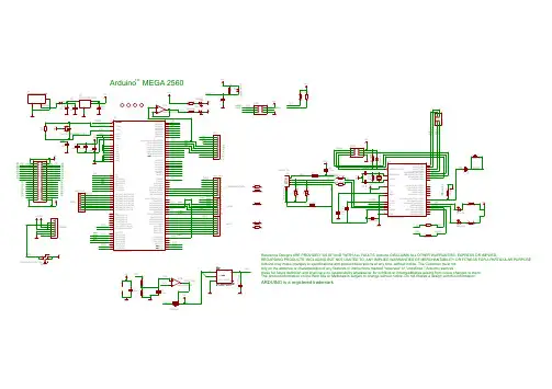
电路图和PCB
▪电路图/en/uploads/Main/arduino-mega2560 -schematic.pdf
▪硬件设计文件(Eagle文件)/en/uploads/Main/arduino-mega25 60-reference-design.zip
▪引脚图/en/Hacking/PinMapping2560
电源
Arduino Mega2560可以通过3种方式供电,而且能自动选择供电方式
▪外部直流电源通过电源插座供电。
▪电池连接电源连接器的GND和VIN引脚。
▪USB接口直接供电。
电源引脚说明
▪VIN --- 当外部直流电源接入电源插座时,可以通过VIN向外部供电;也可以通过此引脚向Mega2560直接供电;VIN有电时
将忽略从USB或者其他引脚接入的电源。
▪5V --- 通过稳压器或USB的5V电压,为UNO上的5V芯片供电。
▪ 3.3V --- 通过稳压器产生的3.3V电压,最大驱动电流50mA。
▪GND --- 地脚。
存储器
ATmega2560包括了片上256KB Flash,其中8KB用于Bootloader。
同时还有8KB SRAM和4KB EEPROM。
输入输出
1.14路数字输入输出口:工作电压为5V,每一路能输出和接入最
大电流为40mA。
每一路配置了20-50K欧姆内部上拉电阻(默
认不连接)。
除此之外,有些引脚有特定的功能
▪4路串口信号:串口0---0(RX)and 1(TX);串口1---19(RX)and 18(TX);串口2---17(RX)and 16(TX);串
口3---15(RX)and 14(TX)。
其中串口0与内部 ATmega8U2
USB-to-TTL 芯片相连,提供TTL电压水平的串口接收信
号。
▪6路外部中断:2(中断0),3(中断 1),18(中断 5),19(中断 4),20(中断 3),and 21(中断 2)。
触发中断引脚,
可设成上升沿、下降沿或同时触发。
▪14路脉冲宽度调制PWM(0--13):提供14路8位PWM 输出。
▪SPI(53(SS),51(MOSI),50(MISO),52(SCK)):SPI通信接口。
▪LED(13号):Arduino专门用于测试LED的保留接口,输出为高时点亮LED,反之输出为低时LED熄灭。
2.16路模拟输入:每一路具有10位的分辨率(即输入有1024个
不同值),默认输入信号范围为0到5V,可以通过AREF调整
输入上限。
除此之外,有些引脚有特定功能
▪TWI接口(20(SDA)和21(SCL)):支持通信接口(兼容I2C总线)。
3.AREF:模拟输入信号的参考电压。
4.Reset:信号为低时复位单片机芯片。
通信接口
1.串口:ATmega2560内置的4路UART可以与外部实现串口通信;
ATmega16U2可以访问串口0实现USB上的虚拟串口。
2.TWI(兼容I2C)接口:
3.SPI 接口:
下载程序
▪Arduino Mega2560上的ATmega2560已经预置了bootloader程序,因此可以通过Arduino软件直接下载程序到Mega2560中,参见[[]]。
▪可以直接通过Mega2560上ICSP header直接下载程序到ATmega2560,参见[[]]。
▪ATmega16U2的Firmware(固件)也可以通过DFU工具升级,参见[[]]。
物理特征
Arduino Mega2560的最大尺寸为4 x 2.1 inches。
注意要点
▪Arduino Mega2560上USB口附近有一个可重置的保险丝,对电路起到保护作用。
当电流超过500mA是会断开USB连接。
▪Arduino Mega2560提供了自动复位设计,可以通过主机复位。
这样通过Arduino软件下在程序到Mega2560中软件可以自动复位,不需要在复位按钮。
在印制板上丝印"RESET EN"处可以使能和禁止该功能。
▪Arduino Mega2560的设计与Arduino USB接口标准版的设计完全兼容,因此用于Arduino UNO和之前系列的扩展板也可以用在Arduino Mega2560上。
扩展阅读
/en/Main/ArduinoBoardMega2560。