coredra
- 格式:docx
- 大小:20.57 KB
- 文档页数:6

“coreld raw防盗版监控”的解决方法CorelD RAW X6,今天打开Core ldraw X6时却弹出错误:尝试重新启动计算机和应用程序。
如果这些操作还是不能解决问题,请卸载应用程序,重新安装。
(错误 38)重新启动计算机和应用程序依然无法解决问题。
虽然重新安装Corel drawX6也许可以解决问题,但是Core ldraw X6激活又成了另外一个麻烦的问题。
那在不重新安装Core ldraw X6的情况下有没有解决办法?首先,我们得了解为什么Cor eldra w X6 启动时会出现错误38?为什么呢?这究竟是为什么呢?其实这都是你手贱的结果。
Coreld raw X6 启动时出现(错误 38)的原因:其问题是Co relDR AW携带安装的防拷贝版权保护软件相关服务进程Psi Servi ce_2.exe没有启动,可能是因为你通过金山卫士或360安全卫士或者其他系统优化软件优化禁用了P ortex is公司的防拷贝版权保护软件监视服务Pr otexi s Licens ing V2引起的故障现象。
你说是不是手贱的原因? Coreld raw X6启动时出现(错误 38多种解决办法: 1、如果你是用过360安全卫士禁用的Prote xis Licens ing V2服务,那么 360安全卫士\开机加速\服务Prot exis防拷贝版权保护软件相关服务设为开机启动,重启电脑,这样你的Co reldr aw X5就可以使用了。
其他优化软件类似,既然它可以禁用服务,那应该也可以启用服务。
2、从开始>运行里输入s ervic es.msc,调出系统服务管理页面,查看Prot exisLicens ing V2 服务是否已停止,停止的话,设置为自启动就行了。

19StandardMath ToolsDisplay up to four math function traces (F1-F4). The easy-to-use graphical interface simplifies setup of up to two operations on each function trace;and function traces can be chained together to perform math-on-math.absolute value integralaverage (summed)invert (negate)average (continuous)log (base e)custom (MATLAB) – limited points product (x)derivativeratio (/)deskew (resample)reciprocaldifference (–)rescale (with units)enhanced resolution (to 11 bits vertical)roof envelope (sinx)/x exp (base e)square exp (base 10)square root fft (power spectrum, magnitude, phase,sum (+)up to 50 kpts) trend (datalog) of 1000 events floorzoom (identity)histogram of 1000 eventsMeasure ToolsDisplay any 6 parameters together with statistics, including their average,high, low, and standard deviations. Histicons provide a fast, dynamic view of parameters and wave-shape characteristics.Pass/Fail TestingSimultaneously test multiple parameters against selectable parameter limits or pre-defined masks. Pass or fail conditions can initiate actions including document to local or networked files, e-mail the image of the failure, save waveforms, send a pulse out at the rear panel auxiliary BNC output, or (with the GPIB option) send a GPIB SRQ.Jitter and Timing Analysis Software Package (WRXi-JTA2)(Standard with MXi-A model oscilloscopes)•Jitter and timing parameters, with “Track”graphs of •Edge@lv parameter (counts edges)• Persistence histogram, persistence trace (mean, range, sigma)Software Options –Advanced Math and WaveShape AnalysisStatistics Package (WRXi-STAT)This package provides additional capability to statistically display measurement information and to analyze results:• Histograms expanded with 19 histogram parameters/up to 2 billion events.• Persistence Histogram• Persistence Trace (mean, range, sigma)Master Analysis Software Package (WRXi-XMAP)(Standard with MXi-A model oscilloscopes)This package provides maximum capability and flexibility, and includes all the functionality present in XMATH, XDEV, and JTA2.Advanced Math Software Package (WRXi-XMATH)(Standard with MXi-A model oscilloscopes)This package provides a comprehensive set of WaveShape Analysis tools providing insight into the wave shape of complex signals. Includes:•Parameter math – add, subtract, multiply, or divide two different parameters.Invert a parameter and rescale parameter values.•Histograms expanded with 19 histogram parameters/up to 2 billion events.•Trend (datalog) of up to 1 million events•Track graphs of any measurement parameter•FFT capability includes: power averaging, power density, real and imaginary components, frequency domain parameters, and FFT on up to 24 Mpts.•Narrow-band power measurements •Auto-correlation function •Sparse function• Cubic interpolation functionAdvanced Customization Software Package (WRXi-XDEV)(Standard with MXi-A model oscilloscopes)This package provides a set of tools to modify the scope and customize it to meet your unique needs. Additional capability provided by XDEV includes:•Creation of your own measurement parameter or math function, using third-party software packages, and display of the result in the scope. Supported third-party software packages include:– VBScript – MATLAB – Excel•CustomDSO – create your own user interface in a scope dialog box.• Addition of macro keys to run VBScript files •Support for plug-insValue Analysis Software Package (WRXi-XVAP)(Standard with MXi-A model oscilloscopes)Measurements:•Jitter and Timing parameters (period@level,width@level, edge@level,duty@level, time interval error@level, frequency@level, half period, setup, skew, Δ period@level, Δ width@level).Math:•Persistence histogram •Persistence trace (mean, sigma, range)•1 Mpts FFTs with power spectrum density, power averaging, real, imaginary, and real+imaginary settings)Statistical and Graphical Analysis•1 Mpts Trends and Histograms •19 histogram parameters •Track graphs of any measurement parameterIntermediate Math Software Package (WRXi-XWAV)Math:•1 Mpts FFTs with power spectrum density, power averaging, real, and imaginary componentsStatistical and Graphical Analysis •1 Mpts Trends and Histograms •19 histogram parameters•Track graphs of any measurement parameteramplitude area base cyclescustom (MATLAB,VBScript) –limited points delay Δdelay duration duty cyclefalltime (90–10%, 80–20%, @ level)firstfrequency lastlevel @ x maximum mean median minimumnumber of points +overshoot –overshoot peak-to-peak period phaserisetime (10–90%, 20–80%, @ level)rmsstd. deviation time @ level topΔ time @ levelΔ time @ level from triggerwidth (positive + negative)x@ max.x@ min.– Cycle-Cycle Jitter – N-Cycle– N-Cycle with start selection – Frequency– Period – Half Period – Width– Time Interval Error – Setup– Hold – Skew– Duty Cycle– Duty Cycle Error20WaveRunner WaveRunner WaveRunner WaveRunner WaveRunner 44Xi-A64Xi-A62Xi-A104Xi-A204Xi-AVertical System44MXi-A64MXi-A104MXi-A204MXi-ANominal Analog Bandwidth 400 MHz600 MHz600 MHz 1 GHz 2 GHz@ 50 Ω, 10 mV–1 V/divRise Time (Typical)875 ps500 ps500 ps300 ps180 psInput Channels44244Bandwidth Limiters20 MHz; 200 MHzInput Impedance 1 MΩ||16 pF or 50 Ω 1 MΩ||20 pF or 50 ΩInput Coupling50 Ω: DC, 1 MΩ: AC, DC, GNDMaximum Input Voltage50 Ω: 5 V rms, 1 MΩ: 400 V max.50 Ω: 5 V rms, 1 MΩ: 250 V max.(DC + Peak AC ≤ 5 kHz)(DC + Peak AC ≤ 10 kHz)Vertical Resolution8 bits; up to 11 with enhanced resolution (ERES)Sensitivity50 Ω: 2 mV/div–1 V/div fully variable; 1 MΩ: 2 mV–10 V/div fully variableDC Gain Accuracy±1.0% of full scale (typical); ±1.5% of full scale, ≥ 10 mV/div (warranted)Offset Range50 Ω: ±1 V @ 2–98 mV/div, ±10 V @ 100 mV/div–1 V/div; 50Ω:±400mV@2–4.95mV/div,±1V@5–99mv/div,1 M Ω: ±1 V @ 2–98 mV/div, ±10 V @ 100 mV/div–1 V/div,±10 V @ 100 mV–1 V/div±**********/div–10V/div 1 M Ω: ±400 mV @ 2–4.95 mV/div, ±1 V @5–99 mV/div, ±10 V @ 100 mV–1 V/div,±*********–10V/divInput Connector ProBus/BNCTimebase SystemTimebases Internal timebase common to all input channels; an external clock may be applied at the auxiliary inputTime/Division Range Real time: 200 ps/div–10 s/div, RIS mode: 200 ps/div to 10 ns/div, Roll mode: up to 1,000 s/divClock Accuracy≤ 5 ppm @ 25 °C (typical) (≤ 10 ppm @ 5–40 °C)Sample Rate and Delay Time Accuracy Equal to Clock AccuracyChannel to Channel Deskew Range±9 x time/div setting, 100 ms max., each channelExternal Sample Clock DC to 600 MHz; (DC to 1 GHz for 104Xi-A/104MXi-A and 204Xi-A/204MXi-A) 50 Ω, (limited BW in 1 MΩ),BNC input, limited to 2 Ch operation (1 Ch in 62Xi-A), (minimum rise time and amplitude requirements applyat low frequencies)Roll Mode User selectable at ≥ 500 ms/div and ≤100 kS/s44Xi-A64Xi-A62Xi-A104Xi-A204Xi-A Acquisition System44MXi-A64MXi-A104MXi-A204MXi-ASingle-Shot Sample Rate/Ch 5 GS/sInterleaved Sample Rate (2 Ch) 5 GS/s10 GS/s10 GS/s10 GS/s10 GS/sRandom Interleaved Sampling (RIS)200 GS/sRIS Mode User selectable from 200 ps/div to 10 ns/div User selectable from 100 ps/div to 10 ns/div Trigger Rate (Maximum) 1,250,000 waveforms/secondSequence Time Stamp Resolution 1 nsMinimum Time Between 800 nsSequential SegmentsAcquisition Memory Options Max. Acquisition Points (4 Ch/2 Ch, 2 Ch/1 Ch in 62Xi-A)Segments (Sequence Mode)Standard12.5M/25M10,00044Xi-A64Xi-A62Xi-A104Xi-A204Xi-A Acquisition Processing44MXi-A64MXi-A104MXi-A204MXi-ATime Resolution (min, Single-shot)200 ps (5 GS/s)100 ps (10 GS/s)100 ps (10 GS/s)100 ps (10 GS/s)100 ps (10 GS/s) Averaging Summed and continuous averaging to 1 million sweepsERES From 8.5 to 11 bits vertical resolutionEnvelope (Extrema)Envelope, floor, or roof for up to 1 million sweepsInterpolation Linear or (Sinx)/xTrigger SystemTrigger Modes Normal, Auto, Single, StopSources Any input channel, External, Ext/10, or Line; slope and level unique to each source, except LineTrigger Coupling DC, AC (typically 7.5 Hz), HF Reject, LF RejectPre-trigger Delay 0–100% of memory size (adjustable in 1% increments, or 100 ns)Post-trigger Delay Up to 10,000 divisions in real time mode, limited at slower time/div settings in roll modeHold-off 1 ns to 20 s or 1 to 1,000,000,000 events21WaveRunner WaveRunner WaveRunner WaveRunner WaveRunner 44Xi-A 64Xi-A 62Xi-A104Xi-A 204Xi-A Trigger System (cont’d)44MXi-A64MXi-A104MXi-A204MXi-AInternal Trigger Level Range ±4.1 div from center (typical)Trigger and Interpolator Jitter≤ 3 ps rms (typical)Trigger Sensitivity with Edge Trigger 2 div @ < 400 MHz 2 div @ < 600 MHz 2 div @ < 600 MHz 2 div @ < 1 GHz 2 div @ < 2 GHz (Ch 1–4 + external, DC, AC, and 1 div @ < 200 MHz 1 div @ < 200 MHz 1 div @ < 200 MHz 1 div @ < 200 MHz 1 div @ < 200 MHz LFrej coupling)Max. Trigger Frequency with400 MHz 600 MHz 600 MHz 1 GHz2 GHzSMART Trigger™ (Ch 1–4 + external)@ ≥ 10 mV@ ≥ 10 mV@ ≥ 10 mV@ ≥ 10 mV@ ≥ 10 mVExternal Trigger RangeEXT/10 ±4 V; EXT ±400 mVBasic TriggersEdgeTriggers when signal meets slope (positive, negative, either, or Window) and level conditionTV-Composite VideoT riggers NTSC or PAL with selectable line and field; HDTV (720p, 1080i, 1080p) with selectable frame rate (50 or 60 Hz)and Line; or CUSTOM with selectable Fields (1–8), Lines (up to 2000), Frame Rates (25, 30, 50, or 60 Hz), Interlacing (1:1, 2:1, 4:1, 8:1), or Synch Pulse Slope (Positive or Negative)SMART TriggersState or Edge Qualified Triggers on any input source only if a defined state or edge occurred on another input source.Delay between sources is selectable by time or eventsQualified First In Sequence acquisition mode, triggers repeatedly on event B only if a defined pattern, state, or edge (event A) is satisfied in the first segment of the acquisition. Delay between sources is selectable by time or events Dropout Triggers if signal drops out for longer than selected time between 1 ns and 20 s.PatternLogic combination (AND, NAND, OR, NOR) of 5 inputs (4 channels and external trigger input – 2 Ch+EXT on WaveRunner 62Xi-A). Each source can be high, low, or don’t care. The High and Low level can be selected independently. Triggers at start or end of the patternSMART Triggers with Exclusion TechnologyGlitch and Pulse Width Triggers on positive or negative glitches with widths selectable from 500 ps to 20 s or on intermittent faults (subject to bandwidth limit of oscilloscope)Signal or Pattern IntervalTriggers on intervals selectable between 1 ns and 20 sTimeout (State/Edge Qualified)Triggers on any source if a given state (or transition edge) has occurred on another source.Delay between sources is 1 ns to 20 s, or 1 to 99,999,999 eventsRuntTrigger on positive or negative runts defined by two voltage limits and two time limits. Select between 1 ns and 20 sSlew RateTrigger on edge rates. Select limits for dV, dt, and slope. Select edge limits between 1 ns and 20 s Exclusion TriggeringTrigger on intermittent faults by specifying the normal width or periodLeCroy WaveStream Fast Viewing ModeIntensity256 Intensity Levels, 1–100% adjustable via front panel control Number of Channels up to 4 simultaneouslyMax Sampling Rate5 GS/s (10 GS/s for WR 62Xi-A, 64Xi-A/64MXi-A,104Xi-A/104MXi-A, 204Xi-A/204MXi-A in interleaved mode)Waveforms/second (continuous)Up to 20,000 waveforms/secondOperationFront panel toggle between normal real-time mode and LeCroy WaveStream Fast Viewing modeAutomatic SetupAuto SetupAutomatically sets timebase, trigger, and sensitivity to display a wide range of repetitive signalsVertical Find ScaleAutomatically sets the vertical sensitivity and offset for the selected channels to display a waveform with maximum dynamic range44Xi-A 64Xi-A 62Xi-A104Xi-A 204Xi-A Probes44MXi-A 64MXi-A104MXi-A 204MXi-AProbesOne Passive probe per channel; Optional passive and active probes available Probe System; ProBus Automatically detects and supports a variety of compatible probes Scale FactorsAutomatically or manually selected, depending on probe usedColor Waveform DisplayTypeColor 10.4" flat-panel TFT-LCD with high resolution touch screenResolutionSVGA; 800 x 600 pixels; maximum external monitor output resolution of 2048 x 1536 pixelsNumber of Traces Display a maximum of 8 traces. Simultaneously display channel, zoom, memory, and math traces Grid StylesAuto, Single, Dual, Quad, Octal, XY , Single + XY , Dual + XY Waveform StylesSample dots joined or dots only in real-time mode22Zoom Expansion TracesDisplay up to 4 Zoom/Math traces with 16 bits/data pointInternal Waveform MemoryM1, M2, M3, M4 Internal Waveform Memory (store full-length waveform with 16 bits/data point) or store to any number of files limited only by data storage mediaSetup StorageFront Panel and Instrument StatusStore to the internal hard drive, over the network, or to a USB-connected peripheral deviceInterfaceRemote ControlVia Windows Automation, or via LeCroy Remote Command Set Network Communication Standard VXI-11 or VICP , LXI Class C Compliant GPIB Port (Accessory)Supports IEEE – 488.2Ethernet Port 10/100/1000Base-T Ethernet interface (RJ-45 connector)USB Ports5 USB 2.0 ports (one on front of instrument) supports Windows-compatible devices External Monitor Port Standard 15-pin D-Type SVGA-compatible DB-15; connect a second monitor to use extended desktop display mode with XGA resolution Serial PortDB-9 RS-232 port (not for remote oscilloscope control)44Xi-A 64Xi-A 62Xi-A104Xi-A 204Xi-A Auxiliary Input44MXi-A 64MXi-A104MXi-A 204MXi-ASignal Types Selected from External Trigger or External Clock input on front panel Coupling50 Ω: DC, 1 M Ω: AC, DC, GND Maximum Input Voltage50 Ω: 5 V rms , 1 M Ω: 400 V max.50 Ω: 5 V rms , 1 M Ω: 250 V max. (DC + Peak AC ≤ 5 kHz)(DC + Peak AC ≤ 10 kHz)Auxiliary OutputSignal TypeTrigger Enabled, Trigger Output. Pass/Fail, or Off Output Level TTL, ≈3.3 VConnector TypeBNC, located on rear panelGeneralAuto Calibration Ensures specified DC and timing accuracy is maintained for 1 year minimumCalibratorOutput available on front panel connector provides a variety of signals for probe calibration and compensationPower Requirements90–264 V rms at 50/60 Hz; 115 V rms (±10%) at 400 Hz, Automatic AC Voltage SelectionInstallation Category: 300 V CAT II; Max. Power Consumption: 340 VA/340 W; 290 VA/290 W for WaveRunner 62Xi-AEnvironmentalTemperature: Operating+5 °C to +40 °C Temperature: Non-Operating -20 °C to +60 °CHumidity: Operating Maximum relative humidity 80% for temperatures up to 31 °C decreasing linearly to 50% relative humidity at 40 °CHumidity: Non-Operating 5% to 95% RH (non-condensing) as tested per MIL-PRF-28800F Altitude: OperatingUp to 3,048 m (10,000 ft.) @ ≤ 25 °C Altitude: Non-OperatingUp to 12,190 m (40,000 ft.)PhysicalDimensions (HWD)260 mm x 340 mm x 152 mm Excluding accessories and projections (10.25" x 13.4" x 6")Net Weight7.26kg. (16.0lbs.)CertificationsCE Compliant, UL and cUL listed; Conforms to EN 61326, EN 61010-1, UL 61010-1 2nd Edition, and CSA C22.2 No. 61010-1-04Warranty and Service3-year warranty; calibration recommended annually. Optional service programs include extended warranty, upgrades, calibration, and customization services23Product DescriptionProduct CodeWaveRunner Xi-A Series Oscilloscopes2 GHz, 4 Ch, 5 GS/s, 12.5 Mpts/ChWaveRunner 204Xi-A(10 GS/s, 25 Mpts/Ch in interleaved mode)with 10.4" Color Touch Screen Display 1 GHz, 4 Ch, 5 GS/s, 12.5 Mpts/ChWaveRunner 104Xi-A(10 GS/s, 25 Mpts/Ch in interleaved mode)with 10.4" Color Touch Screen Display 600 MHz, 4 Ch, 5 GS/s, 12.5 Mpts/Ch WaveRunner 64Xi-A(10 GS/s, 25 Mpts/Ch in interleaved mode)with 10.4" Color Touch Screen Display 600 MHz, 2 Ch, 5 GS/s, 12.5 Mpts/Ch WaveRunner 62Xi-A(10 GS/s, 25 Mpts/Ch in interleaved mode)with 10.4" Color Touch Screen Display 400 MHz, 4 Ch, 5 GS/s, 12.5 Mpts/Ch WaveRunner 44Xi-A(25 Mpts/Ch in interleaved mode)with 10.4" Color Touch Screen DisplayWaveRunner MXi-A Series Oscilloscopes2 GHz, 4 Ch, 5 GS/s, 12.5 Mpts/ChWaveRunner 204MXi-A(10 GS/s, 25 Mpts/Ch in Interleaved Mode)with 10.4" Color Touch Screen Display 1 GHz, 4 Ch, 5 GS/s, 12.5 Mpts/ChWaveRunner 104MXi-A(10 GS/s, 25 Mpts/Ch in Interleaved Mode)with 10.4" Color Touch Screen Display 600 MHz, 4 Ch, 5 GS/s, 12.5 Mpts/Ch WaveRunner 64MXi-A(10 GS/s, 25 Mpts/Ch in Interleaved Mode)with 10.4" Color Touch Screen Display 400 MHz, 4 Ch, 5 GS/s, 12.5 Mpts/Ch WaveRunner 44MXi-A(25 Mpts/Ch in Interleaved Mode)with 10.4" Color Touch Screen DisplayIncluded with Standard Configuration÷10, 500 MHz, 10 M Ω Passive Probe (Total of 1 Per Channel)Standard Ports; 10/100/1000Base-T Ethernet, USB 2.0 (5), SVGA Video out, Audio in/out, RS-232Optical 3-button Wheel Mouse – USB 2.0Protective Front Cover Accessory PouchGetting Started Manual Quick Reference GuideAnti-virus Software (Trial Version)Commercial NIST Traceable Calibration with Certificate 3-year WarrantyGeneral Purpose Software OptionsStatistics Software Package WRXi-STAT Master Analysis Software Package WRXi-XMAP (Standard with MXi-A model oscilloscopes)Advanced Math Software Package WRXi-XMATH (Standard with MXi-A model oscilloscopes)Intermediate Math Software Package WRXi-XWAV (Standard with MXi-A model oscilloscopes)Value Analysis Software Package (Includes XWAV and JTA2) WRXi-XVAP (Standard with MXi-A model oscilloscopes)Advanced Customization Software Package WRXi-XDEV (Standard with MXi-A model oscilloscopes)Spectrum Analyzer and Advanced FFT Option WRXi-SPECTRUM Processing Web Editor Software Package WRXi-XWEBProduct Description Product CodeApplication Specific Software OptionsJitter and Timing Analysis Software Package WRXi-JTA2(Standard with MXi-A model oscilloscopes)Digital Filter Software PackageWRXi-DFP2Disk Drive Measurement Software Package WRXi-DDM2PowerMeasure Analysis Software Package WRXi-PMA2Serial Data Mask Software PackageWRXi-SDM QualiPHY Enabled Ethernet Software Option QPHY-ENET*QualiPHY Enabled USB 2.0 Software Option QPHY-USB †EMC Pulse Parameter Software Package WRXi-EMC Electrical Telecom Mask Test PackageET-PMT* TF-ENET-B required. †TF-USB-B required.Serial Data OptionsI 2C Trigger and Decode Option WRXi-I2Cbus TD SPI Trigger and Decode Option WRXi-SPIbus TD UART and RS-232 Trigger and Decode Option WRXi-UART-RS232bus TD LIN Trigger and Decode Option WRXi-LINbus TD CANbus TD Trigger and Decode Option CANbus TD CANbus TDM Trigger, Decode, and Measure/Graph Option CANbus TDM FlexRay Trigger and Decode Option WRXi-FlexRaybus TD FlexRay Trigger and Decode Physical Layer WRXi-FlexRaybus TDP Test OptionAudiobus Trigger and Decode Option WRXi-Audiobus TDfor I 2S , LJ, RJ, and TDMAudiobus Trigger, Decode, and Graph Option WRXi-Audiobus TDGfor I 2S LJ, RJ, and TDMMIL-STD-1553 Trigger and Decode Option WRXi-1553 TDA variety of Vehicle Bus Analyzers based on the WaveRunner Xi-A platform are available.These units are equipped with a Symbolic CAN trigger and decode.Mixed Signal Oscilloscope Options500 MHz, 18 Ch, 2 GS/s, 50 Mpts/Ch MS-500Mixed Signal Oscilloscope Option 250 MHz, 36 Ch, 1 GS/s, 25 Mpts/ChMS-500-36(500 MHz, 18 Ch, 2 GS/s, 50 Mpts/Ch Interleaved) Mixed Signal Oscilloscope Option 250 MHz, 18 Ch, 1 GS/s, 10 Mpts/Ch MS-250Mixed Signal Oscilloscope OptionProbes and Amplifiers*Set of 4 ZS1500, 1.5 GHz, 0.9 pF , 1 M ΩZS1500-QUADPAK High Impedance Active ProbeSet of 4 ZS1000, 1 GHz, 0.9 pF , 1 M ΩZS1000-QUADPAK High Impedance Active Probe 2.5 GHz, 0.7 pF Active Probe HFP25001 GHz Active Differential Probe (÷1, ÷10, ÷20)AP034500 MHz Active Differential Probe (x10, ÷1, ÷10, ÷100)AP03330 A; 100 MHz Current Probe – AC/DC; 30 A rms ; 50 A rms Pulse CP03130 A; 50 MHz Current Probe – AC/DC; 30 A rms ; 50 A rms Pulse CP03030 A; 50 MHz Current Probe – AC/DC; 30 A rms ; 50 A peak Pulse AP015150 A; 10 MHz Current Probe – AC/DC; 150 A rms ; 500 A peak Pulse CP150500 A; 2 MHz Current Probe – AC/DC; 500 A rms ; 700 A peak Pulse CP5001,400 V, 100 MHz High-Voltage Differential Probe ADP3051,400 V, 20 MHz High-Voltage Differential Probe ADP3001 Ch, 100 MHz Differential Amplifier DA1855A*A wide variety of other passive, active, and differential probes are also available.Consult LeCroy for more information.Product Description Product CodeHardware Accessories*10/100/1000Base-T Compliance Test Fixture TF-ENET-B †USB 2.0 Compliance Test Fixture TF-USB-B External GPIB Interface WS-GPIBSoft Carrying Case WRXi-SOFTCASE Hard Transit CaseWRXi-HARDCASE Mounting Stand – Desktop Clamp Style WRXi-MS-CLAMPRackmount Kit WRXi-RACK Mini KeyboardWRXi-KYBD Removable Hard Drive Package (Includes removeable WRXi-A-RHD hard drive kit and two hard drives)Additional Removable Hard DriveWRXi-A-RHD-02* A variety of local language front panel overlays are also available .† Includes ENET-2CAB-SMA018 and ENET-2ADA-BNCSMA.Customer ServiceLeCroy oscilloscopes and probes are designed, built, and tested to ensure high reliability. In the unlikely event you experience difficulties, our digital oscilloscopes are fully warranted for three years, and our probes are warranted for one year.This warranty includes:• No charge for return shipping • Long-term 7-year support• Upgrade to latest software at no chargeLocal sales offices are located throughout the world. Visit our website to find the most convenient location.© 2010 by LeCroy Corporation. All rights reserved. Specifications, prices, availability, and delivery subject to change without notice. Product or brand names are trademarks or requested trademarks of their respective holders.1-800-5-LeCroy WRXi-ADS-14Apr10PDF。

core data 基础概念(最新版)目录1.什么是 core data2.Core data 的作用3.Core data 的组成4.Core data 的优缺点5.Core data 的应用实例正文【1.什么是 core data】Core Data 是苹果公司开发的一款用于管理应用程序数据的框架,它可以帮助开发者高效地存储、管理和访问数据。
Core Data 可以应用于各种类型的应用程序,如桌面应用程序、iOS 应用程序和 macOS 应用程序。
【2.Core data 的作用】Core Data 的主要作用是简化数据管理,它提供了一套完整的数据管理解决方案,包括数据的存储、检索、更新和删除等操作。
Core Data 还提供了数据验证和数据持久化等功能,使得开发者可以更加专注于应用程序的业务逻辑。
【3.Core data 的组成】Core Data 主要由以下几个部分组成:- 实体 (Entity):实体是 Core Data 中数据的基本单元,它代表了现实世界中的一个具体的对象,如一个人、一辆车等。
- 属性 (Attribute):属性是实体的组成部分,它代表了实体的某个特征,如姓名、年龄等。
- 关系 (Relationship):关系是用于连接实体之间的桥梁,它可以表示现实世界中的各种关系,如一对一、一对多和多对多等。
- 存储 (Storage):存储是 Core Data 中用于存储数据的地方,它可以是文件、数据库或内存等。
- 查询 (Query):查询是 Core Data 提供的一种数据检索方式,它可以帮助开发者高效地检索和操作数据。
【4.Core data 的优缺点】Core Data 的优点包括:- 简化了数据管理:Core Data 提供了一套完整的数据管理解决方案,使得开发者可以更加专注于应用程序的业务逻辑。
- 提供了数据验证:Core Data 可以对数据进行验证,确保数据的正确性和完整性。

文章标题:探索 Core X Chroma 手册的功能与特性一、引言在现代科技领域,外设产品以其创新性和多功能性成为了用户选择的焦点。
而Razer公司的Core X Chroma外置显卡扩展坞,则作为一个高性能外设产品,备受用户青睐。
本文将对Core X Chroma手册进行全面评估,深入探讨其功能与特性,为读者全面、深刻地揭示Core X Chroma的内涵。
二、功能与特性1. 外观设计Core X Chroma外观采用具有未来感的铝合金外壳,轻巧便携,同时又具有足够的散热性能。
其采用了Razer标志性的绿色RGB灯效设计,为用户带来炫酷的外观体验。
2. 显示接口Core X Chroma扩展坞提供了多种显示接口,包括HDMI、DisplayPort等,能够满足用户在不同场景下的显示输出需求。
3. 扩展功能Core X Chroma在显卡扩展的基础上,还具备了USB接口、千兆网口等扩展功能,为用户提供了更为便捷的外设连接方式。
4. Chroma RGB灯效作为其名字的一部分,Core X Chroma拥有丰富多彩的Chroma RGB灯效,用户可以通过Razer Synapse软件进行个性化设置,创造出属于自己的炫酷灯效,丰富了用户的使用体验。
5. 散热设计Core X Chroma采用了优秀的散热设计,保证了在高负载时显卡的稳定性与性能表现。
三、个人观点在本文所讨论的所有功能与特性中,我认为Chroma RGB灯效所带来的视觉冲击力是Core X Chroma的一大亮点。
通过对灯光的自定义设置,用户可以将其与其他Razer产品相匹配,创造出个性化的工作环境。
这种个性化设计不仅能够提升工作效率,还能够为用户带来更为舒适与愉悦的工作体验。
四、总结与回顾通过对Core X Chroma手册的深入探讨,我们对其功能与特性有了更为全面、深刻的了解。
其外观设计、显示接口、扩展功能、Chroma RGB灯效以及散热设计等方面的创新,为用户带来了前所未有的外设使用体验。

捕捉目标工具在工具-选项ctrl+j形状工具F10 , 像皮擦工具x 缩放工具z 手绘工具F5 艺术笔工具I 智能绘图工具s 矩形工具F6 椭圆工具F7 图纸工具 D 多边形工具Y 螺纹工具 A 文字工具F8 轮廓画笔对话框F12 轮廓颜色对话框shift+F12 填充对话框shift+F11 渐变填充对话框F11 交互式填充工具G 交互式网格填充M 编辑撤消删除,重做c+s+z,重复c+r,剪贴,复制,粘贴,选择性粘贴,删除,符号(新建,编辑,完成编辑,还原到对象,中断链接,符号管理器ctrl+F6),再制c+d,复制属性自,叠印轮廓,叠印填充,全选(对象,文体,辅助线,节点),查找和替换(查找或替换=对象或文本,插入因特网对象,插入条行码,插入新对象,对象,链接,属性alt+enter视图简单线框,线框,草稿,正常,增强,全屏预览F9,只预览选定对象O,页面排序器视图A,标尺R,网格G,辅助线I,显示H(页边框,出血,可打印区,叠印填充,文本框),启动翻滚,对齐网格c+y,对齐辅助线,对齐对象alt+z,动态导线alt+shift+d,网格和标尺设置,辅助线设置,对齐对象设置,动态导线设置,版面插入页,删除页面,重命名页面,转到某页,切换页面方向,页设置,页面背景,排列A变换(位置A+F7,旋转A+F8,比例A+F9,大小A+F10,倾斜),清除变换,对齐和分布(左L,右R,顶R端,底端B,水平居中E,垂直居中C,在页面居中P,),顺序(到前部shift+pgup,到后部shift+pgdn,向前一位ctrl+pgup,向后一位ctrl+pgdn,在前面,在后面,逆序),群组ctrl+g,取消群组ctrl+u,取消全部群组,结合ctrl+L,拆分ctrl+k,锁定对象,解除锁定对象,解除锁定全部对象,造型(焊接,修剪,相交,简化,前减后,后减前,),转换为曲线ctrl+q,将轮廓转换为对象c+s+q,闭合路径,效果C艺术笔,调和,轮廓图c+ F9,封套C+F7,立体化,透镜A+F3,添加透视点,图框精确剪裁(放在容器中,提取内容,编辑内容,完成编辑翻滚),翻滚,清除效果,复制效果,克隆效果,位图转换为位图,编辑位图,裁剪位图,跟踪位图,重新取样,模式,扩位图边框,位图颜色遮罩,中断链接,自链接更新,文体文本格式C+T,编辑文本C+S+T,插入字符C+F11,使文本适合路径,按文本框显示文本,对齐基线A+F12,矫正文本,书写工具,编码,更换大小写,生成WEB兼容文本,转换C+F8,文本统计信息,显示非打印字符,链接,断开链接,工具选项C+J,自定义,颜色管理,设置另存为默认设置D,对象管理器,对象数据管理器,视图管理器C+F2,链接管理器,撤消泊坞窗,因特尔书签管理器,颜色样式S,调色板编辑器,图形和文字样式C+F5,集锦簿,创建,窗口新建窗口,层叠,水平平铺,垂直平铺,排列图标,调色板,泊坞窗,工具栏,刷新窗口ctrl+w(重1镜像对象:就是将对象在水平或垂直方向上进行翻转,所有的对象都可以进行镜像处理。


Guida all'installazione Switch Gigabit Ethernet Unmanaged da 5 e 8 porte Modello GS305v3 e GS308v3Contenuto della confezione• Switch• Alimentatore (varia in base all'area geografica)• Guida all'installazionei cavi Ethernet non sono inclusi.1. Registrazione tramite l'app NETGEAR InsightUtilizzare l'app NETGEAR Insight per registrare lo switch, attivare la garanzia eaccedere al supporto tecnico.1. Sul dispositivo mobile iOS o Android in uso, accedere all'App Store, cercareNETGEAR Insight e scaricare l'app più recente.2. Aprire l'app NETGEAR Insight.3. Se non è stato ancora configurato un account NETGEAR, toccare CreateNETGEAR Account (Crea account NETGEAR) e seguire le istruzionivisualizzate sullo schermo.4. Toccare il menu nell'angolo in alto a sinistra per aprirlo.5. Toccare REGISTER ANY NETGEAR DEVICE (REGISTRA QUALSIASIDISPOSITIVO NETGEAR).6. Immettere il numero di serie riportato sulla parte inferiore dello switchoppure utilizzare la fotocamera del proprio dispositivo mobile o tablet peracquisire il codice a barre del numero di serie.7. Quindi toccare Go (Vai).8. Per aggiungere lo switch alla rete, toccare View Device (Visualizzadispositivo).A questo punto, lo switch risulta registrato e aggiunto all'account. È orapossibile visualizzare lo switch nell'app NETGEAR Insight.Nota: poiché si tratta di uno switch unmanaged, non è possibile configurarlo ogestirlo in NETGEAR Insight.2. Collegamento dello switchNel diagramma delle connessioni di esempio, l'intera rete viene distribuita inambienti interni.Se si desidera collegare un dispositivo esterno allo switch, collegare lo switcha un dispositivo di protezione da sovratensione Ethernet che supporta lestesse velocità dello switch, quindi collegare il dispositivo di protezione dasovratensione al dispositivo esterno.Non utilizzare lo switch in ambienti esterni. Prima di collegare questo interruttorea cavi o dispositivi esterni, consultare https:///000057103 perinformazioni sulla sicurezza e sulla garanzia.3. Accensione dello switch• Nel caso si utilizzi uno switch modello GS308v3, spostare l'interruttore Off/On (Spento/Acceso) sulla posizione On (Acceso).•Collegare l'adattatore di alimentazione allo switch e a una presa di corrente.Access PointRouterGS305v3Collegamenti di esempioNETGEAR, Inc.piazza della Repubblica 32 20124 Milano NETGEAR INTL LTDFloor 1, Building 3, University Technology Centre Curraheen Road, Cork,T12EF21, Irlanda© NETGEAR, Inc. NETGEAR e il logo NETGEAR sono marchi di NETGEAR, Inc. Qualsiasi marchio non‑NETGEAR è utilizzato solo come riferimento.Supporto e CommunityVisita /support per trovare le risposte alle tue domande e accedere agli ultimi download.Puoi cercare anche utili consigli nella nostra Community NETGEAR, visitando la pagina .Conformità normativa e note legaliPer la conformità alle normative vigenti, compresa la Dichiarazione di conformità UE, visitare il sito Web https:///about/regulatory/.Prima di collegare l'alimentazione, consultare il documento relativo alla conformità normativa.I LED indicano lo stato.LED DescrizionePower (Alimentazione)• Acceso. Lo switch è collegato all'alimentazione.• Spento. Lo switch non è collegato all'alimentazione.Porta• Verde senza intermittenza. Lo switch ha rilevato uncollegamento con un dispositivo acceso su questa porta.• Lampeggia in verde. La porta invia o riceve traffico.• Spento. Lo switch non rileva nessun collegamento suquesta porta.Aprile 2020。


C O NF ID EN T IA LNSi8120/NSi8121/NSi8122: High ReliabilityDual-Channel Digital IsolatorsDatasheet (EN) 1.8Product OverviewThe NSi812x devices are high reliability dual-channel digital isolator. The NSi812x device is safety certified by UL1577 support several insulation withstand voltages (3.75kV rms , 5kV rms ), while providing high electromagnetic immunity and low emissions at low power consumption. The data rate of the NSi812x is up to 150Mbps, and the common-mode transient immunity (CMTI) is up to 150kV/us. The NSi812x device provides digital channel direction configuration and the default output level configuration when the input power is lost. Wide supply voltage of the NSi812x device support to connect with most digital interface directly, easy to do the level shift. High system level EMC performance enhance reliability and stability of use. AEC-Q100 (Grade 1) option is provided for all devices.Key Features• Up to 5000V rms Insulation voltage• Date rate: DC to 150Mbps• Power supply voltage: 2.5V to 5.5V • All devices are AEC-Q100 qualified • High CMTI: 150kV/us • Chip level ESD: HBM: ±6kV• High system level EMC performance:Enhanced system level ESD, EFT, Surge immunity• Default output high level or low level option • Isolation barrier life: >60 years• Low power consumption: 1.5mA/ch (1 Mbps) • Low propagation delay: <15ns • Operation temperature: -40℃~125℃ • RoHS-compliant packages:SOIC-8 narrow body SOIC-16 wide bodySafety Regulatory Approvals• UL recognition: up to 5000V rms for 1 minute per UL1577• CQC certification per GB4943.1-2011• CSA component notice 5A • DIN VDE V 0884-11:2017-01Applications• Industrial automation system • Isolated SPI, RS232, RS485• General-purpose multichannel isolation • Motor controlFunctional Block DiagramsC O NF ID EN T IA LIndex1.0 ABSOLUTE MAXIMUM RATINGS .............................................................................................................................. 3 2.0 SPECIFICATIONS ........................................................................................................................................................... 3 2.1. E LECTRICAL CHARACTERISTICS .................................................................................................................................................. 3 2.2. TYPICAL PERFORMANCE CHARACTERISTICS ........................................................................................................................... 7 2.3. P ARAMETER M EASUREMENT I NFORMATION . (8)3.0 HIGH VOLTAGE FEATURE DESCRIPTION (9)3.1. INSULATION AND SAFETY RELATED SPECIFICATIONS (9)3.2. DIN VDE V 0884-11(VDE V 0884-11):2017-01 INSULATION CHARATERISTICS ....................................................................... 9 3.3. R EGULATORY INFORMATION ................................................................................................................................................... 11 4.0 FUNCTION DESCRIPTION ..........................................................................................................................................11 5.0 APPLICATION NOTE ................................................................................................................................................... 12 5.1. PCB L AYOUT ...................................................................................................................................................................... 12 5.2. H IGH SPEED PERFORMANCE ................................................................................................................................................... 12 5.3. T YPICAL S UPPLY C URRENT E QUATIONS ..................................................................................................................................... 13 6.0 PACKAGE INFORMATION ......................................................................................................................................... 13 7.0 TAPE AND REEL INFORMATION ............................................................................................................................. 17 8.0 ORDER INFORMATION .............................................................................................................................................. 20 9.0 REVISION HISTORY . (21)C O NF ID EN T IA L1.0 ABSOLUTE MAXIMUM RATINGSPower Supply Voltage VDD1, VDD2 -0.5 6.5 V Maximum Input Voltage VINA, VINB -0.4 VDD+0.41 V Maximum Output Voltage V OUTA , V OUTB -0.4 VDD+0.41 VMaximum Input/Output Pulse VoltageVINA, VINB, V OUTA , V OUTB-0.8VDD+0.8VPulse width should be less than 100ns, and the duty cycle should be less than 10%Common-Mode Transients CMTI ±150 kV/us Output currentIo -15 15mAMaximum Surge Isolation VoltageV IOSM5.3kVOperating Temperature Topr -40125 ℃Storage Temperature Tstg -40150℃Electrostatic dischargeHBM±6000VCDM±2000V1 The maximum voltage must not exceed 6.5V.2.0 SPECIFICATIONS2.1. ELECTRICAL CHARACTERISTICS(VDD1=2.5V~5.5V, VDD2=2.5V~5.5V, Ta=-40℃ to 125℃. Unless otherwise noted, Typical values are at VDD1 = 5V, VDD2 = 5V, Ta =25℃)Power on ResetVDD POR2.2 V POR threshold as during power-upVDD HYS 0.1 V POR threshold Hysteresis Input ThresholdV IT1.6 V Input Threshold at rising edge V IT_HYS 0.4 V Input Threshold Hysteresis High Level Input Voltage V IH 2 V Low Level Input Voltage V IL 0.8 V High Level Output Voltage V OH VDD-0.3 V I OH ≤ 4mA Low Level Output VoltageV OL0.3VI OL ≤ 4mAC O NF ID EN T IA LOutput Impedance R out 50 ohm Input Pull high or low CurrentI pull 8 15 uA Start Up Time after POR trbs 40 usec Common Mode Transient ImmunityCMTI±100±150kV/us(VDD1=5V± 10%, VDD2=5V± 10%, Ta=-40℃ to 125℃. Unless otherwise noted, Typical values are at VDD1 = 5V, VDD2 = 5V, Ta = 25℃)Supply currentNSi8120 I DD1(Q0) 0.58 0.87 mAAll Input 0V for NSi8120x0 Or All Input at supply for NSi8120x1 I DD2(Q0) 1.18 1.77 mA I DD1(Q1) 2.92 4.38 mA All Input at supply for NSi8120x0 Or All Input 0V for NSi8120x1I DD2(Q1) 1.241.86mAI DD1(1M) 1.71 2.56 mA All Input with 1Mbps, C L =15pFI DD2(1M)1.382.07mAI DD1(10M) 1.78 2.67 mA All Input with 10Mbps, C L =15pF I DD2(10M)3.24.8mA I DD1(100M)2.103.15 mA All Input with 100Mbps, C L =15pFI DD2(100M)21.031.5mANSi8121/ NSi8122 I DD1(Q0) 1.031.55 mA All Input 0V for NSi812xx0 Or All Input at supply for NSi812xx1 I DD2(Q0) 1.00 1.5 mA I DD1(Q1)2.203.3 mA All Input at supply for NSi812xx0Or All Input 0V for NSi812xx1 I DD2(Q1)2.133.2 mA I DD1(1M) 1.72 2.58 mA All Input with 1Mbps, C L =15pFI DD2(1M) 1.68 2.52 mA I DD1(10M) 2.62 3.93 mA All Input with 10Mbps, C L =15pFI DD2(10M) 2.71 4.06 mA I DD1(100M) 11.01 16.5 mA All Input with 100Mbps, C L = 15pF I DD2(100M)12.8 19.2 mA Data RateDR 0 150 MbpsC O NF ID EN T IA LPropagation Delayt PLH 5 8.20 15 ns See Figure 2.7 , C L = 15pF t PHL 5 10.56 15 ns See Figure 2.7, C L = 15pF Pulse Width Distortion |t PHL – t PLH | PWD5.0nsSee Figure 2.7 , C L = 15pFRising Time t r 5.0 ns See Figure 2.7 , C L = 15pF Falling Timet f 5.0 ns See Figure 2.7 , C L = 15pFPeak Eye Diagram Jitter t JIT (PK) 350 ps Channel-to-Channel Delay Skewt SK (c2c) 2.5 nsPart-to-Part Delay Skewt SK (p2p)5.0ns(VDD1=3.3V± 10%, VDD2=3.3V± 10%, Ta=-40℃ to 125℃. Unless otherwise noted, Typical values are at VDD1 = 3.3V, VDD2 = 3.3V, Ta =25℃)Supply currentNSi8120 I DD1(Q0) 0.550.83mA All Input 0V for NSi8120x0 Or All Input at supply for NSi8120x1 I DD2(Q0) 1.12 1.68 mA I DD1(Q1) 2.87 4.3 mA All Input at supply for NSi8120x0 Or All Input 0V for NSi8120x1 I DD2(Q1)1.18 1.77mA I DD1(1M)1.72.55mA All Input with 1Mbps, C L = 15pFI DD2(1M)1.271.91 mA I DD1(10M) 1.732.6 mA All Input with 10Mbps, C L = 15pF I DD2(10M)2.413.6 mA I DD1(100M) 2.05 3.08 mA All Input with 100Mbps, C L = 15pF I DD2(100M)14.0521.08mANSi8121/ NSi8122 I DD1(Q0) 0.98 1.47 mA All Input 0V for NSi812xx0 Or All Input at supply for NSi812xx1 I DD2(Q0) 0.95 1.43 mA I DD1(Q1) 2.14 3.21 mA All Input at supply for NSi812xx0 Or All Input 0V for NSi812xx1 I DD2(Q1) 2.08 3.12 mA I DD1(1M) 1.63 2.45 mA All Input with 1Mbps, C L = 15pFI DD2(1M) 1.59 2.39 mA I (10M)2.223.33mAAll Input with 10Mbps,C O NF I D EN T IA LI DD2(10M) 2.25 3.38 mA C L = 15pFI DD1(100M) 7.57 11.36 mA All Input with 100Mbps, C L = 15pF I DD2(100M)8.5 12.75 mA Data RateDR 0 150 Mbps Minimum Pulse Width PW 5.0 nsPropagation Delayt PLH 5 9.20 15 ns See Figure 2.7 , C L = 15pF t PHL5 10.40 15 ns See Figure 2.7, C L = 15pF Pulse Width Distortion |t PHL – t PLH | PWD5.0nsSee Figure 2.7 , C L = 15pFRising Time t r 5.0 ns See Figure 2.7 , C L = 15pF Falling Timet f5.0 nsSee Figure 2.7 , C L = 15pFPeak Eye Diagram Jitter t JIT (PK) 350psChannel-to-Channel Delay Skewt SK (c2c)2.5nsPart-to-Part Delay Skew t SK (p2p)5.0ns(VDD1=2.5V± 10%, VDD2=2.5V± 10%, Ta=-40℃ to 125℃. Unless otherwise noted, Typical values are at VDD1 = 2.5V, VDD2 = 2.5V, Ta =25℃)Supply currentNSi8120I DD1(Q0) 0.53 0.8 mA All Input 0V for NSi8120x0 Or All Input at supply for NSi8120x1 I DD2(Q0) 1.11.65 mA I DD1(Q1)2.85 4.28 mA All Input at supply for NSi8120x0 Or All Input 0V for NSi8120x1 I DD2(Q1)1.15 1.73 mA I DD1(1M) 1.632.45 mA All Input with 1Mbps, C L = 15pFI DD2(1M) 1.21 1.82 mA I DD1(10M) 1.68 2.52 mA All Input with 10Mbps, C L = 15pFI DD2(10M) 2.05 3.08 mA I DD1(100M) 1.95 2.93 mA All Input with 100Mbps, C L = 15pFI DD2(100M)10.415.6mANSi8121/ NSi8122I DD1(Q0) 0.96 1.44 mA All Input 0V for NSi812xx0 Or All Input at supply for NSi812xx1I (Q0)0.931.395mAF ID EN T IA LI DD1(Q1) 2.11 3.165 mA All Input at supply for NSi812xx0Or All Input 0V for NSi812xx1 I DD2(Q1) 2.05 3.075 mA I DD1(1M) 1.58 2.37 mA All Input with 1Mbps, C L = 15pFI DD2(1M) 1.54 2.31 mA I DD1(10M) 2.02 3.03 mA All Input with 10Mbps, C L = 15pFI DD2(10M) 2.04 3.06 mA I DD1(100M) 6.03 9.045 mA All Input with 100Mbps, C L = 15pF I DD2(100M)6 9 mAData RateDR 0 150 Mbps Minimum Pulse Width PW 5.0 nsPropagation Delayt PLH 5 10 15 nsSee Figure 2.7 , C L = 15pF t PHL5 10 15nsSee Figure 2.7, C L = 15pFPulse Width Distortion |t PHL – t PLH | PWD5.0nsSee Figure 2.7 , C L = 15pFRising Time t r5.0ns See Figure 2.7 , C L = 15pF Falling Timet f5.0 ns See Figure 2.7 , C L = 15pFPeak Eye Diagram Jitter t JIT (PK)350ps Channel-to-Channel Delay Skewt SK (c2c)2.5ns Part-to-Part Delay Skew t SK (p2p)5.0ns2.2. TYPICAL PERFORMANCE CHARACTERISTICSFigure 2.1 NSi8120 VDD1 Supply Current vs Data Rate Figure 2.2 NSi8120 VDD2 Supply Current vs Data RateC OE2.3. PARAMETER MEASUREMENT INFORMATIONC LFigure 2.7 Switching Characteristics Test Circuit and WaveformFigure 2.8 Common-Mode Transient Immunity Test CircuitC O NF ID EN T IA L3.0 HIGH VOLTAGE FEATURE DESCRIPTION3.1. INSULATION AND SAFETY RELATED SPECIFICATIONSMinimum External Air Gap (Clearance)L(I01) 4.0 8.0 mm Shortest terminal-to-terminal distance through air Minimum External Tracking (Creepage)L(I02)4.08.0mmShortest terminal-to-terminal distance across the package surfaceMinimum internal gap DTI 20 um Distance through insulationTrackingResistance(Comparative Tracking Index) CTI>400VDIN EN 60112 (VDE 0303-11); IEC 60112Material GroupⅡ3.2. DIN VDE V 0884-11(VDE V 0884-11):2017-01 INSULATION CHARATERISTICSSOIC-8 SOIC-16 Installation Classification per DIN VDE 0110For Rated Mains Voltage ≤ 150V rms Ⅰto Ⅳ Ⅰto Ⅳ For Rated Mains Voltage ≤ 300V rms Ⅰto Ⅲ Ⅰto Ⅳ For Rated Mains Voltage ≤ 400V rms Ⅰto Ⅲ Ⅰto Ⅳ Climatic Classification10/105/2110/105/21 Pollution Degree per DIN VDE 0110, Table 122Maximum repetitive isolation voltageVIORM 565 849 Vpeak Input to Output Test Voltage, Method B1V IORM × 1.5 = V pd (m) , 100%production test, t ini = t m = 1 sec, partial discharge < 5 pCV pd (m)8471273VpeakInput to Output Test Voltage, Method AAfter Environmental Tests Subgroup 1V IORM × 1.2= V pd (m) , t ini = 60 sec, t m = 10 sec, partial V pd (m)6781018VpeakC O N T IA LAfter Input and /or Safety Test Subgroup 2 and Subgroup 3 V IORM × 1.2= V pd (m) , t ini = 60 sec, t m = 10 sec, partialdischarge < 5 pC V pd (m)6781018VpeakMaximum transient isolation voltage t = 60 sec VIOTM 5300 7000 Vpeak Maximum Surge Isolation VoltageTest method per IEC60065,1.2/50uswaveform, VTEST=VIOSM×1.3VIOSM53845384VpeakIsolation resistance VIO =500V RIO >109 >109 Ω Isolation capacitance f = 1MHzCIO 0.6 0.6pFInput capacitanceCI22pF Total Power Dissipation at 25℃Ps1499 mW Safety input, output, or supply currentθJA = 140 °C/W, V I = 5.5 V, T J = 150 °C, T A = 25 °C Is160mAθJA = 84 °C/W, V I = 5.5 V, T J = 150 °C, T A = 25 °C237 mA Case TemperatureTs150150℃Figure 3.2 NSi8120W/NSi8121W/NSi8122W Thermal Derating Curve, Dependence of Safety Limiting Values with Case Temperature per DIN VDE V 0884-11C O NF ID EN T IA L3.3. REGULATORY INFORMATIONThe NSi8120N/NSi8121N/NSi8122N are approved by the organizations listed in table.UL 1577 Component Recognition Program 1Approved under CSA ComponentAcceptance Notice 5ADIN VDE V 0884-11:2017-012Certified by CQC11-471543-2012 GB4943.1-2011Single Protection, 3750V rms Isolation voltageSingle Protection, 3750V rms IsolationvoltageBasic Insulation 565Vpeak, V IOSM =5384VpeakBasic insulation at 400V rms (565Vpeak)File (E500602)File (E500602)File (5024579-4880-0001)File (pending)1 In accordance with UL 1577, each NSi8120N/NSi8121N/NSi8122N is proof tested by applying an insulation test voltage ≥ 4500 Vrms for 1 sec.2 In accordance with DIN VDE V 0884-11, each NSi8120N/NSi8121N/NSi8122N is proof tested by applying an insulation test voltage ≥ 847 V peak for 1 sec(partial discharge detection limit = 5 pC). The * marking branded on the component designates DIN VDE V 0884-11 approval.The NSi8120W/NSi8121W/NSi8122W are approved by the organizations listed in table.UL 1577 Component Recognition Program 1Approved under CSAComponent Acceptance Notice5ADIN VDE V 0884-11(VDE V 0884-11):2017-012 Certified by CQC11-471543-2012 GB4943.1-2011Single Protection, 5000V rms Isolation voltageSingle Protection, 5000V rmsIsolation voltageBasic Insulation 849Vpeak, V IOSM =5384Vpeak Basic insulation at 800V rms (1131Vpeak) Reinforced insulation at 400V rms (565Vpeak)File (E500602)File (E500602)File (5024579-4880-0001)File (pending)1 In accordance with UL 1577, each NSi8120W/NSi8121W/NSi8122W is proof tested by applying an insulation test voltage ≥ 6000 V rms for 1 sec.2 In accordance with DIN VDE V 0884-11, each NSi8120W/NSi8121W/NSi8122W is proof tested by applying an insulation test voltage ≥ 1273 V peak for 1 sec(partial discharge detection limit = 5 pC). The * marking branded on the component designates DIN VDE V 0884-11 approval.4.0 FUNCTION DESCRIPTIONThe NSi812x is a Dual-channel digital isolator based on a capacitive isolation barrier technique. The digital signal is modulated with RF carrier generated by the internal oscillator at the Transmitter side. Then it is transferred through the capacitive isolation barrier and demodulated at the Receiver side.The NSi812x devices are high reliability dual-channel digital isolator with AEC-Q100 qualified. The NSi812x device is safety certified by UL1577 support several insulation withstand voltages (3.75kV rms , 5kV rms ), while providing high electromagnetic immunity and low emissions at low power consumption. The data rate of the NSi812x is up to 150Mbps, and the common-mode transient immunity (CMTI) is up to 150kV/us. The NSi812x device provides digital channel direction configuration and the default output level configuration when the input power is lost. Wide supply voltage of the NSi812x device support to connect with most digital interface directly, easy to do the level shift. High system level EMC performance enhance reliability and stability of use.The NSi812x has a default output status when VDDIN is unready and VDDOUT is ready as shown in Table 4.1, which helps for diagnosis when power is missing at the transmitter side. The output B follows the same status with the input A within 1us after powering up.C O NF ID EN T IA LCopyright © 2019, NOVOSENSEPage 12 Table 4.1 Output status vs. power statusH Ready Ready H Normal operation.L Ready Ready L XUnreadyReadyL HThe output follows the same status with the input within 60us after input side VDD1 is powered on.X Ready Unready XThe output follows the same status with the input within 60us after output side VDD2 is powered on.5.0 APPLICATION NOTE5.1. PCB LAYOUTThe NSi812x requires a 0.1 µF bypass capacitor between VDD1 and GND1, VDD2 and GND2. The capacitor should beplaced as close as possible to the package. Figure 5.1 to Figure 5.4 show the recommended PCB layout, make sure the space under the chip should keep free from planes, traces, pads and via. To enhance the robustness of a design, the user may also include resistors (50–300 Ω ) in series with the inputs and outputs if the system is excessively noisy. The series resistors also improve the system reliability such as latch-up immunity.The typical output impedance of an isolator driver channel is approximately 50 Ω, ±40%. When driving loads where transmission line effects will be a factor, output pins should be appropriately terminated with controlled impedance PCB traces.Figure5.1 Recommended PCB Layout — Top Layer Figure5.2 Recommended PCB Layout — Bottom LayerFigure5.3 Recommended PCB Layout — Top Layer Figure5.4 Recommended PCB Layout — Bottom Layer5.2. HIGH SPEED PERFORMANCEFigure 5.5 shows the eye diagram of NSi812x at 200Mbps data rate output. The result shows a typical measurement on the NSi812x with 350ps p-p jitter.C O NF ID EN T IA LFigure5.5 NSi812x Eye Diagram5.3. TYPICAL SUPPLY CURRENT EQUATIONSThe typical supply current of NSi812x can be calculated using below equations. I DD1 and I DD2 are typical supply currents measured in mA, f is data rate measured in Mbps, C L is the capacitive load measured in pFNSi8120:I DD1 = 0.19 *a1+1.45*b1+0.82*c1. I DD2 = 1.36+ VDD1*f* C L *c1*10-9When a1 is the channel number of low input at side 1, b1 is the channel number of high input at side 1, c1 is the channel number of switch signal input at side 1.NSi8121/ NSi8122:I DD1 = 0.87 +1.26*b1+0.63*c1+ VDD1*f* C L *c2*10-9I DD2 = 0.87 +1.26*b2+0.63*c2+ VDD1*f* C L *c1*10-9When b1 is the channel number of high input at side 1, c1 is the channel number of switch signal input at side 1, b2 is the channel number of high input at side 2, c2 is the channel number of switch signal input at side 2.6.0 PACKAGE INFORMATIONVDD GND 22VDD INA GND 2VDD 2Figure 6.1 NSi8120N Package Figure 6.2 NSi8121N PackageC O NF ID EN T IA LVDD INBGND 22Figure 6.3 NSi8122N PackageFigure 6.4 SOIC8 Package Shape and Dimension in millimeters (inches)Table6.1 NSi8120N/ NSi8121N/ NSi8122N Pin Configuration and DescriptionNSi8121N PIN NO.NSi8122N PIN NO.SYMBOL FUNCTION1 1 1 VDD1 Power Supply for Isolator Side 12 7 2 INA Logic Input A3 3 6 INB Logic Input B4 4 4 GND1 Ground 1, the ground reference for Isolator Side 15 5 5 GND2 Ground 2, the ground reference for Isolator Side 26 6 3 OUTB Logic Output B7 2 7 OUTA Logic Output A888VDD2Power Supply for Isolator Side 2C O NFVDD GND GND 2VDD 2GND 2GND NC NCNC VDD GND GND 2VDD 22GND NC NC NCFigure 6.5 NSi8120W Package Figure 6.6 NSi8121W PackageVDD INB GND GND 2VDD 2GND 2GND NC NC NCFigure 6.7 NSi8122W PackageFigure 6.8 WB SOIC16 Package Shape and Dimension in millimeters and (inches)C O NF ID EN T IA LTable 6.2 NSi8120W/ NSi8121W/ NSi8122W Pin Configuration and Description1 1 1 GND1 Ground 1, the ground reference for Isolator Side 12 2 2 NC No Connection.3 3 3 VDD1 Power Supply for Isolator Side 14 13 4 INA Logic Input A5 5 12 INB Logic Input B6 6 6 NC No Connection.7 7 7 GND1 Ground 1, the ground reference for Isolator Side 18 8 8 NC No Connection. 9 9 9 GND2 Ground 2, the ground reference for Isolator Side 210 10 10 NC No Connection. 11 11 11 NC No Connection. 12 12 5OUTB Logic Output A 13 4 13OUTALogic Output B 14 14 14 VDD2 Power Supply for Isolator Side 215 15 15 NC No Connection.161616GND2Ground 2, the ground reference for Isolator Side 27.0TAPE AND REEL INFORMATIONLAITNEDIFNOCC O NF ID EN T IA LFigure 7.1 Tape and Reel Information of SOIC8LAITNEDIFNOCFigure 7.2 Tape and Reel Information of WB SOIC16NF ID EN T IA L8.0 ORDER INFORMATIONNSi8120N0 3.75 2 0 150 Low -40 to 125℃ NO SOIC8 NSi8120N1 3.75 2 0 150 High -40 to 125℃ NO SOIC8 NSi8121N0 3.75 1 1 150 Low -40 to 125℃ NO SOIC8 NSi8121N1 3.75 1 1 150 High -40 to 125℃ NO SOIC8 NSi8122N0 3.75 1 1 150 Low -40 to 125℃ NO SOIC8 NSi8122N1 3.75 1 1 150 High -40 to 125℃ NO SOIC8 NSi8120W0 5 2 0 150 Low -40 to 125℃ NO WB SOIC16 NSi8120W1 5 2 0 150 High -40 to 125℃ NO WB SOIC16 NSi8121W0 5 1 1 150 Low -40 to 125℃ NO WB SOIC16 NSi8121W1 5 1 1 150 High -40 to 125℃ NO WB SOIC16 NSi8122W0 5 1 1 150 Low -40 to 125℃ NO WB SOIC16 NSi8122W1 5 1 1 150 High -40 to 125℃ NO WB SOIC16 NSi8120N0Q 3.75 2 0 150 Low -40 to 125℃ YES SOIC8 NSi8120N1Q 3.75 2 0 150 High -40 to 125℃ YES SOIC8 NSi8121N0Q 3.75 1 1 150 Low -40 to 125℃ YES SOIC8 NSi8121N1Q 3.75 1 1 150 High -40 to 125℃ YES SOIC8 NSi8122N0Q 3.75 1 1 150 Low -40 to 125℃ YES SOIC8 NSi8122N1Q 3.75 1 1 150 High -40 to 125℃ YES SOIC8 NSi8120W0Q 5 2 0 150 Low -40 to 125℃ YES WB SOIC16 NSi8120W1Q 5 2 0 150 High -40 to 125℃ YES WB SOIC16 NSi8121W0Q 5 1 1 150 Low -40 to 125℃ YES WB SOIC16 NSi8121W1Q 5 1 1 150 High -40 to 125℃ YES WB SOIC16 NSi8122W0Q 5 1 1 150 Low -40 to 125℃ YES WB SOIC16 NSi8122W1Q 5 1 1 150 High -40 to 125℃YES WB SOIC16 NOTE: All packages are RoHS-compliant with peak reflow temperatures of 260 °C according to the JEDEC industry standard classifications and peak solder temperatures. All devices are AEC-Q100 qualified.Part Number Rule:NSi(81)(2)(1)(N)(1)(Q)C O NF ID EN T IA LNSi8120/NSi8121/NSi81229.0 REVISION HISTORY1.0 Original2017/11/15 1.1 Change to Ordering information2018/3/26 1.2 Add maximum operation current specification. 2018/6/20 1.3 Change block diagram 2018/7/28 1.4 Correct Table 6.2 Pin No.2018/8/20 1.5 Add specification “Input Pull high or low Current” 2018/9/10 1.6 Add “Maximum Input/Output Pulse Voltage” 2018/10/91.7 Change to Ordering information 2018/12/20 1.8 Change Certification Information2019/06/17。

MedDRA术语简介什么是MedDRA术语MedDRA(Medical Dictionary for Regulatory Activities)是一个用于医药领域的术语分类系统,用于记录和报告医药产品的不良事件和药物副作用。
MedDRA术语由国际药监机构联盟(International Council for Harmonisation of Technical Requirements for Pharmaceuticals for Human Use,简称ICH)开发和维护。
MedDRA术语是一个多层级的分类系统,包含了各种医药领域的术语和概念。
它的设计目的是帮助医药研究人员和监管机构在临床试验、药物监管和药物安全评估等方面进行统一的术语使用。
MedDRA术语的结构MedDRA术语由各种术语组成,这些术语分为五个不同的层级,包括系统器官类别(System Organ Class,SOC)、高级术语组(High Level Term,HLT)、一般术语组(Preferred Term,PT)、低级术语组(Low Level Term,LLT)和术语描述(Term Description)。
•系统器官类别(SOC)是MedDRA术语的最高级别,用于对术语进行整体分类,例如”神经系统疾病”、“循环系统疾病”等。
•高级术语组(HLT)是SOC下的第二级分类,用于更详细地描述与SOC相关的术语,例如”中枢神经系统疾病”、“心血管系统疾病”等。
•一般术语组(PT)是HLT下的第三级分类,用于进一步细分与HLT相关的术语,例如”头痛”、“心脏病”等。
•低级术语组(LLT)是PT下的第四级分类,用于更具体地描述与PT相关的术语,例如”偏头痛”、“心肌梗死”等。
•术语描述(Term Description)提供了对术语的详细描述和定义。
MedDRA术语的应用MedDRA术语在医药领域的应用非常广泛,主要用于以下方面:1.不良事件报告:医药研究人员和监管机构使用MedDRA术语来记录和报告与药物治疗相关的不良事件和药物副作用。

血竭Xuejie(活血化淤,树脂,棕榈科)血竭Xuejie (活血化淤,树脂,棕榈科)拉丁名SANGUIS DRAXONIS别名麒麟竭,海蜡,麒麟血,木血竭。
来源为棕榈科植物麒麟竭Daemonorops draco Bl.果实渗出的树脂经加工制成。
原植物形态多年生常绿藤本,长l0~20m。
茎具叶鞘并遍生尖刺。
羽状复叶在枝梢上互生,在下部有时近对生;叶柄及叶轴具锐刺;小叶线状披针形,长20~30cm,宽约3cm,先端锐尖,基部狭,脉3出,平行。
肉穗花序,开淡黄色冠状花,单性,雌雄异株;花被6,排成2轮;雄花雄蕊6,花药长锥形;雌花有不育雄蕊6,雌蕊1,瓶状,子房略呈卵状,密被鳞片,花柱短,柱头3深裂。
果实核果状,卵状球形,径2~3cm,赤褐色,具黄色鳞片,果实内含深赤色的液状树脂,常由鳞片下渗出,干后如血块状。
种子1颗。
药材性状本品略呈类圆四方形或方砖形,表面暗红粉,有光泽,附有因摩擦而成的红粉。
质硬而脆,破碎面红色,研粉为砖红色。
气微,味淡。
在水中不溶,在热水中软化。
生境分布分布于印度尼西亚、马来西亚、伊朗,我国台湾、广东有栽培,主产于印度尼西亚、印度、马来西亚等地。
我国进口血竭多系印度尼西亚原装血竭,或由新加坡进口的加工血竭。
采收加工除去杂质,打成碎粒或研成细末。
性味归经甘、咸,平。
归心、肝经。
功能主治祛瘀定痛,止血生肌。
用于跌扑折损,内伤瘀痛;外伤出血不止。
用量用法内服:研末,1~2g,或入丸剂。
外用:研末撒或入膏药用。
化学成分含树脂类、脂肪酸类、三萜等。
药理作用有抗炎、抑菌、抗血栓作用。
血竭鉴别本品为较常用中药。
商品为棕榈科植物麒麟竭果实渗出的树脂。
血竭通常分为加工血竭和原装血竭。
历史血竭原名:"骐麟竭",始载于《唐本草》,原与紫铆(音矿)同条。
本草纲目释名血竭。
李时珍谓:"骐麟亦马名也:此物如干血,故谓之血竭。
曰骐麟者隐之也。
旧与紫铆同条,紫铆乃此树上虫所造成";李时珍又谓:"骐麟竭是树脂,紫铆是虫造,按一统志:血竭树略如没药树,其肌赤色。

INODOROS Y MUEBLES DE BAÑO El presente certificado cubre cualquier defecto de fabricación del producto que pueda afectar su desempeño y en cumplimiento de lo establecido en el manual de instalación, uso y mantenimiento.CENTRO CERAMICO LAS FLORES SAC, certifica la garantía de los sanitarios de la marca Origin, Golden Bath, Bravat, Trébol Platinum y Noken según las siguientes condiciones: presentación del documento de venta, factura o boleta (original o virtual).2.Si presenta defectos de fabricación del producto y no por fallas que se presenten como consecuencia de lainadecuada instalación, reparación, uso o un mal mantenimiento. Garantía sólo cubre el valor del componente a cambiar, si fuese necesario se hará cambio total del producto, no cubre mano de obra traslado, ni otros gastos por remover o instalar productos.4.En caso se reportara alguna deficiencia del sanitario o mueble, comunicarse con el área de Servicio Técnico de CENTRO CERAMICO LAS FLORES SAC quien verificará a fin de establecer la idoneidad y calidad del producto. Garantía no contempla rajaduras ni roturas originadas por golpe que se den en el transporte y/o almacenaje inadecuado.Es muy importante que revise su mercadería al momento de recibirla dando su conformidad de la misma. Garantía fuera de Lima Metropolitana aplica en la ciudades donde se encuentran las tiendas Cassinelli; en otras ciudades la visita técnica a solicitud del cliente se realizará previa cotización y la validación del cliente a asumir el costo que demande la visita hacia la ciudad donde se encuentre instalado el producto. En caso el producto presentara falla de fabricación se aplicará lagarantía según el punto número 3, brindando la atención en tienda.7.No colocar peso excesivo y/o subirse sobre el mueble y tampoco sobre los inodoros.8.No exponer el producto directamente al sol.9.Evite contacto directo del agua o cualquier otro liquido sobre el mueble de baño para evitar la filtración en el interior de la estructura y se produzca hinchamiento.10.Evitar golpear bruscamente al cerrar las puertas y cajones.11.Evitar arrojar papeles dentro del inodoro.Tiempos de Cobertura:El presente certificado de garantía para one pieces, inodoros, bowls,lavatorios y muebles de baño tendrán vigencia a partir de la fecha de compra del producto indicado en su documento de compra.INFORMACION A CONSIDERARLos sanitarios presentarán curaciones ( parches ) en algunas zonas no visibles de la loza (inodoros o lavatorios).En el proceso de fabricación a altas temperaturas se hallan orificios que son necesarios para la ventilación y pequeñas fisuras que se dan en el proceso de enfriamiento tanto en la base interna y tanque del inodoro e igual forma por debajo del lavatorio.Tener en consideración que la loza sanitaria puede presentar defectos de esmalte permisible según norma técnica de fabricación.no debiendo ser visible a más de 1 metro de distancia de la zona frontal y lateral del producto.TREBOL PLATINUM ORIGIN De por Vida (defecto Fábrica)Accesorio interno (3 años)Complementos (1 año)GOLDEN BATH De por Vida (defecto Fábrica)Accesorio interno (1 año) Complementos(6 meses)3 años1 año Accesorio interno (3 años)Complementos (1 año)De por Vida (defecto Fábrica)LAVATARIOS Y MUEBLESMueble Golden Bath 3 años 6 mesesMueble Trébol Platinum 3 años1 año Mueble Origin CERTIFICADO DE GARANTIASANITARIOS Y MUEBLES DE BAÑOBRAVAT MARCA TABLEROGABINETE LOZA SANITARIA MARCA 2 años10 años NOKEN TIEMPOS DE GARANTIA DE SANITARIOS1 año5 años ACCESORIO Y COMPLEMENTOInspiramos el cambio en tuCERTIFICADO DE GARANTIA INODOROS Y MUEBLES DE BAÑOINSTALACION 1.Contratar personal calificado para la instalación de los productos adquiridos.2.Revisar los componentes del producto antes de la instalación (hacer lectura del manual propio de instalación o video brindado).3.Antes de instalar el inodoro se debe verificar si la medida del eje del punto de desagüe de piso o pared va acorde con la del inodoro,asimismo considerar la medida del punto de agua.4.El tubo de desagüe y la toma de agua, tanto interior como exterior, deben encontrarse libres de impurezas y residuos de cemento que puedan atorar el drenaje de agua.5.Para una instalación de inodoro al piso se debe marcar la posición de los pernos de anclaje en la superficie de forma paralela a la pared terminada, posteriormente perforar e instalar los pernos.6.Colocar el anillo de cera alrededor del desagüe del inodoro luego asentar el inodoro al piso y se asegura en la posición definitiva colocando los pernos de anclaje y ajustando a la loza. El anillo debe formar un sello entre el piso y el inodoro para evitar la salida de malos olores y filtraciones de agua. Hacer pruebas de funcionamiento antes de sellar. fijación del borde de la taza al piso o lavatorios de loza, debe realizarse con alguna silicona neutra para uso sanitario.Este producto permite desmontar la loza sin quebrarla (no usar productos que imposibiliten el desmontaje)MANTENIMIENTOSANITARIOS*Para la limpieza de la loza sanitaria no debe usarse materiales abrasivos como escobilla de alambre o similares que pueden deteriorar el acabado de la loza sanitaria.*Combinar los químicos de limpieza con agua antes de su aplicación para evitar dañar el acabado cromado de las bisagras decorativas,pulsadores o el mismo asiento.MUEBLES DE BAÑO*Los lavatorios de loza deben ser limpiados con agua y jabón líquido utilizando una esponja suave.*Posteriormente secar con un paño para evitar manchas.*Evitar acumulación de agua sobre el mueble, podría generar hinchamiento en su estructura..*Limpiar el mueble únicamente con paño ligeramente húmedo.*No aplicar detergentes y evitar la limpieza con esponjas abrasivas ya sea en el lavatorio y el propio mueble de baño.*Es importante la limpieza diaria de la loza para evitar manchas en la superficie (se recomienda utilizar bicarbonato de sodio y vinagre blanco para eliminar la mancha en la loza).Los datos personales que usted proporciona serán utilizados y/o tratados por Centro Cerámico Las Flores SAC estricta y únicamente a efectos de brindarle atención personalizada para la gestión de una posible solución del inconveniente reportado, así como para la acreditación de la atención del mismo. Centro Cerámico Las Flores SAC podrá compartir y/o usar y/o almacenar y/o transferir su información a terceras personas vinculadas o no a Centro Cerámico Las Flores SAC. sean estos socios comerciales o no de Centro Cerámico Las Flores SAC, con el objeto de realizar las actividades relacionadas a la atención post ventas y/o servicio técnico solicitado. Usted podrá ejercer en cualquier momento su derecho de información, acceso, rectificación, cancelación y oposición de sus datos de acuerdo a lo dispuesto por la Ley de Protección de Datos Personales, vigente y su Reglamento. Para más información en la web ó por correo a ********************************.Nombre de Titular de Compra ………………………………………………………………………………………………………………………………………………………………………..Numero de Boleta o Factura ………………………………………....……………………………………………………….Fecha de Compra …………………………………….DNI ………………………………………………………………………………………………………………………………..……….Firma ………………………………………………………….Nombre de Contacto ………………………………………………………………………………………………………..…….Firma de Contacto ………………………………………INSTALACION Y MANTENIMIENTO DE INODOROS Y MUEBLES DE BAÑOServicio Técnico CCLFTeléfono 0800-1-2150 / 241-5753 / 243-2242/ 241-5746Contáctenosvíaweb:******************************************************Inspiramos el cambio en tu hogar INSTALACION Y MATENIMIENTODE INODOROS Y MUEBLES DE BAÑO。
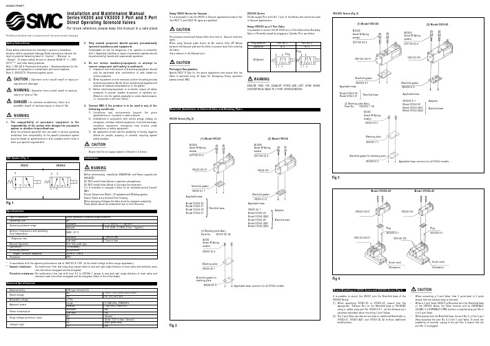
Installation and Maintenance ManualSeries VK300 and VK3000 3 Port and 5 Port Direct Operating Solenoid ValvesThis Manual should be read in conjunction with the current product CatalogueFor future reference,please keep this manual in a safe placeThese safety instructions are intended to prevent a hazardous situation and/or equipment damage.These instructions indicate the level of potential hazard by label of “Caution”,“Warning”or “Danger”.To ensure safety,be sure to observe ISO4414 (Note1),JIS B 8370 (Note2)and other safety practices.Note 1:ISO 4414:Pneumatic fluid power – Recommendations for the application of equipment to transmission and control systems.Note 2:JIS B 8370:Pneumatic system axiom.CAUTION :Operator error could result in injury orequipment damage.WARNING:Operator error could result in serious injury or loss of life.DANGER :In extreme conditions, there is apossible result of serious injury or loss of life.1.The compatibility of pneumatic equipment is theresponsibility of the person who designs the pneumatic system or decides its specifications.Since the products specified here are used in various operatingconditions,their compatibility for the specific pneumatic system must be based on specifications or after analysis and/or tests tomeet your specific requirements.2.Only trained personnel should operate pneumaticallyoperated machinery and equipment.Compressed air can be dangerous if an operator is unfamiliar with it.Assembly,handling or repair of pneumatic systems should be performed by trained and experienced operators.3.Do not service machinery/equipment or attempt toremove component until safety is confirmed.1) Inspection and maintenance of machinery/equipment shouldonly be performed after confirmation of safe locked-out control positions.2) When equipment is to be removed,confirm the safety processas mentioned above.Switch off air and electrical supplies and exhaust all residual compressed air in the system.3)Before machinery/equipment is re-started,ensure all safetymeasures to prevent sudden movement of cylinders etc.(Bleed air into the system gradually to create back-pressure,i.e.incorporate a soft-start valve).4.Contact SMC if the product is to be used in any of thefollowing conditions:1)Conditions and environments beyond the givenspecifications,or if product is used outdoors.2)Installations in conjunction with atomic energy,railway,airnavigation,vehicles,medical equipment,food and beverage,recreation equipment,emergency stop circuits,press applications,or safety equipment.3)An application which has the possibility of having negativeeffects on people,property,or animals,requiring special safety analysis.Ensure that the air supply system is filtered to 5 micron.ENSURE THAT THE EXHAUST PORTS ARE LEFT OPEN WHEN CONVERTING A VALVE TO 3 PORT CONFIGURATION.VK300-TFM71Specifications Type of operation Direct operated 2-position single solenoid Operating fluid AirStandard Operating pressure rangeVacuum Ambient temperature and operating fluid temperature MAX.50 ºC Standard * Response timeLow wattManual Operation Non-lock push type LubricationUnnecessary Mounting positionAny position ** Impact,vibration resistance 300m/s 2,50m/s ProtectionIP65*In accordance with the dynamic performance test of JIS B 8374-1981 (at the rated voltage,**Impact resistance:No malfunction from test using drop impact tester to axis and right angle direction of main valve and armature,one time when energised and de-energised.Vivration resistance:No malfunction from test with from 8.3 to 2000Hz 1 sweep to axis and right angle direction of main valve andarmature each time when energised and de-energised (Value in the initial stage).Solenoid Specifications Electrical entry DIN type terminal (D)AC Rated voltage DC Allowable voltage ±10%Inrush Apparent power Holding Standard Power consumptionLow watt AC Surge voltage protection circuit Fig 1PlugPlug231425134242513513M3X26Screw W/Spring washer Manifold gasketDXT199-23-4M3X8Screw W/Spring washer Blanking plate VK300-33-3VK3000-7-1Manifold gasket for blanking plateVK3000-6-3M3X26Screw W/Spring washer DXT199-23-4VK3120-OG-01VK3140-OGVK3000-6-1Manifold gasket VK3000-6-2Applicable base Model VV5k3-20Model VV5k3-21Manifold base}Applicable base VK3000-9-1Model VV5k3-40Model VV5k3-(S)41Model VV5k3-(S)42Manifold baseSubplate }(3) Blanking plate Ass’y Parts No.:VK3000-7-1AApplicable base:common for all VV5k3 modelsFig 2(1) Model VK332(2) Model VK334M3X26Screw W/Spring washerManifold gasket DXT199-23-4M3X26Screw W/Spring washer DXT199-23-4VK332-OG-01VK334-OGVK300-41-1VK300-33-3Manifold gasketVK300-41-2Applicable base Model VV3k3-20Model VV3k3-21Model VV5k3-20Model VV5k3-21Manifold baseManifold baseSubplate }Applicable baseVK300-45-1Model VV3k3-40Model VV3k3-(S)42Model VV5k3-40Model VV5k3-(S)41Model VV5k3-(S)42(3) Blanking plate Ass’y Parts No.:VK300-42-1A M3X8Screw W/Spring washer VK300-42-1Blanking plate VK300-41-3Manifold gasket for blanking plateApplicable base:common for all VV3k3 models}Mixed Mounting of VK300 Series and VK3000 Series (Fig 4)It is possible to mount the VK300 onto the Manifold base of the VK3000 Series.When specifying VV5K3-20 or VV5K3-40,ensure that theappropriate Exhaust Port on the Manifold base is PLUGGED using a rubber plug part No.VK3000-8-1,as this Exhaust port becomes redundant when mounting 3 port Valves.The 3 port Valve can also be mounted on additional Manifolds i.e.VV5K3-21,VV5K3-(S)41 and VV5K3-(S) 42 without additional modifications.CAUTION•When converting a 5 port Valve,from 3 ports back to 5 ports ensure that the exhaust plug is removed.•When a 3 port Valve (VK300) is Mounted onto the Manifold base of the VK3000 Series,the Valve function will be NORMALLY CLOSED.If a NORMALL Y OPEN function is required plug port No.of a 5 port Valve.•When piping from the Manifold base,the port No.Valve becomes the port No.4 of the 5 port Valve.possibility of incorrect piping to the port No.port No.2 is plugged.Model VV5K3-20VK332-OG-01VK3120-OG-01Plug VK3000-8-1Plug VK3000-8-1Notch mark (Recession)Notch mark (Recession)VK334-OGModel VV5K3-40VK3140-OGConnection Method for Lamp/Surge Voltage Protection Circuit (Fig 7)When using a DIN connector with DC voltage connect the positive side (-) to the symbol 2 of the terminal block.Part No.of the connector without lamp:VK300-82-1Part No.of the connector with lamp:Refer to the following table Rated voltage *Marking Parts No.AC100V 100V VK300-82-2-01AC110V 110V VK300-82-2-03AC200V 200V VK300-82-2-02AC220V 220V VK300-82-2-04AC240V 240V VK300-82-2-07DC6V 6V VK300-82-4-51DC12V 12V VK300-82-4-06DC24V 24VD VK300-82-3-05DC48V48VDVK300-82-3-53*Indicated on the terminal block.Changing the Direction of the Connector (Cable)After separating the Terminal block from the housing,the cable direction can be changed 4 ways at 90º intervals.WARNINGIf the connector is fitted with a lamp,ensure that the lamp is not damaged by the lead wire of the cable.Applicable Cable.( 2 conductors or 3* conductors)Outside diameter of the cable should be ø3.5 ~ ø7mm.Note 3 Conductor cables are used when connecting to Ground.CAUTIONEnsure that the connector is straight during insertion or removal.Piping tightening torque Connecting screwAppropriate tightening torqueN•m {kgf•cm}M5 1.5~2{15~20}Rc (PT) 1/87~9 {70~90}LubricationThe valve has been lubricated for life on assembly and requires no additional lubrication.element.Keep the residual leakage voltage to 20% or less of the rated voltage for AC coils and 2% or less of the rated voltage for DC coils.MaintenanceWARNINGWhen changing the rated voltage the valve MUST be replaced,as it is NOT possible to change the coil.It is NOT possible to dismantle the valve due to its design.Application of undue force to the valve may damage the valve section.Neon glow lamp with DC,connect the positive side to the Red lead wire and the Negative side to the Black the Blue lead wire is for 100VAC,and the Red Fig 7Varistor Varistor LED LED V a r i s t o rNo.1No.2No.2No.1(+)No.2(-)DiodeNo.1(+)2D i o d eRed (+)Black (-)Surge voltage protection circuitFig 9When you enquire about the product,please contact the following SMC Corporation :ENGLAND Phone 01908-563888TURKEY Phone 212-2211512ITALY Phone 02-92711GERMANY Phone 6103-402-0HOLLAND Phone 020-*******FRANCE Phone 01-64-76-10-00SWITZERLAND Phone 052-396 31 31SWEDEN Phone 08-603 07 00SPAIN Phone 945-184100AUSTRIA Phone 02262-62-280Phone 902-255255IRELAND Phone 01-4501822GREECE Phone 01-3426076DENMARK Phone 70 25 29 00FINLAND Phone 09-68 10 21NORWAY Phone 67-12 90 20BELGIUM Phone 03-3551464POLAND Phone 48-22-6131847PORTUGAL Phone 02-610 8922*Marking*MarkingFor AC and DC 12V or less For DC 24V or moreLight (built in connector)Surge voltage protection circuit (built into the terminal block)AC circuit drawingNL:Neon lamp R:ResistorDC circuit drawing 12V or lessLED:Light emitting diode R:ResistorDC circuit drawing 24V or moreD:Protective diodeLED:Light emitting diode R:Resistor*C o n t a c t p o i n tC -R e l e m e n tCurrent leakageVoltage leakageValvePower sourceC o i lC o i lCoilCoil CoilCoil No.1No.2No.1No.2No.1Neon glow lamp DiodeD i o d eNo.2No.12No.1V a r i s t o rFig 6Fixing screwHousing(Code)Refer to table below Terminal screw (3 places)Slotted area(Light installation position)Terminal block Grommet (Rubber)WasherGland nut。

在iOS应用中使用Core Data数据库随着移动应用的普及和功能的增加,数据管理变得越来越重要。
Core Data是苹果公司提供的一种数据持久化框架,它可以帮助开发者在iOS应用中高效地管理和操作数据。
本文将介绍如何在iOS应用中使用Core Data数据库。
1. Core Data简介Core Data是苹果公司提供的一种面向对象的数据持久化框架,它可以帮助开发者管理应用中的数据模型、数据存储和数据操作。
使用Core Data可以减少开发者编写数据库相关代码的工作量,提高开发效率。
2. 创建数据模型在使用Core Data之前,首先需要创建数据模型。
数据模型是应用中数据的结构和关系的描述,它使用实体(Entity)、属性(Property)和关系(Relationship)来定义数据的结构。
可以通过Xcode的数据模型编辑器来创建和编辑数据模型。
3. 数据持久化存储Core Data提供了多种数据持久化存储的方式,包括SQLite、二进制文件和内存等。
可以根据应用的需求选择适合的存储方式。
在创建数据模型时,可以选择数据模型的存储类型。
4. 创建数据上下文数据上下文(NSManagedObjectContext)是Core Data中操作数据的核心对象。
通过数据上下文可以进行数据的插入、删除、修改和查询等操作。
在应用启动时,需要创建一个数据上下文对象,并将其与持久化存储关联起来。
5. 插入数据使用Core Data插入数据非常简单。
首先需要创建一个实体对象,然后设置实体对象的属性值,最后将实体对象插入到数据上下文中。
数据上下文会负责将数据保存到持久化存储中。
6. 查询数据Core Data提供了强大的查询功能,可以通过谓词(NSPredicate)来过滤和排序数据。
可以使用谓词来创建查询条件,然后将查询条件传递给数据上下文的查询方法,即可获取符合条件的数据。
7. 更新和删除数据使用Core Data更新和删除数据也非常方便。

La desforradora de cables neumática de mesa WS-1000 de Molex desforra una amplia gama de cables AWG y métricos, así como aislamientos, lo cual permitelograr ciclos más cortos de las engarzadoras en aplicaciones de fabricantes bajo contrato y fabricantes de arnesesLa desforradora de cables neumática de mesa WS-1000 es capaz de desforrar aislamientos de cable estándar tipo PVC desde 0,03 mm2hasta 6,00 mm2(10 hasta 32 AWG) con la cuchilla estándar en V que viene con la máquina. Esta desforradora de cables semiautomática puede utilizarse con diferentes tipos de aislamiento fabricados con materiales naturales y sintéticos, como caucho, PUR y Teflon*.Esta desforradora de cables es de bajo costo, tiene controles neumáticos, es de funcionamiento semiautomático sobre la mesa de trabajo y está destinada paravolúmenes intermedios de producción. Si desea obtener información adicional, visite: /link/ws1000.html.Desforradora de cablesWS-1000 neumática, de mesa 63801-9200Desforradora de cables,de mesa, para cables AWG 63801-9250Desforradora de cables,de mesa, para cables conmedidas en sistema métricoCARACTERÍSTICAS Y VENTAJAS•Desforra cables desde 10 hasta 32 AWG y cables con medidas en sistema métrico, lo cual permitirá reducir las inversiones en otras máquinas para preparación de cables.•Desforra múltiples tipos de aislamientos y cables, tales como, entre otros: caucho, Teflon, cable para conexiones, cables planos, cable PUR y más, lo cual resulta en menores inversiones.•El cable acciona la máquina; se reduce la duración del ciclo ya que no se requiere accionamiento con un pedal separado.•La cuchilla estándar en V se ajusta a unaamplia gama de diámetros de cable paradesforrado sin necesidad de herramientas,para lograr rápidamente cambios en laproducción.•Las mordazas de sujeción autocentrantes ylos sensores de liberación aseguran la altacalidad, la seguridad y la eficiencia deldesforrado de cables.•Se puede modificar la cuchilla según lasespecificaciones del cliente para adaptarlaa múltiples tipos de cables por lo cual esmuy versátil.•El regulador estándar del filtro estádiseñado para usar aire comprimido hastaun máximo de 6 bar (87 psi) y permiteasegurar que la presión del aire no excedalos valores límites máximos para evitardaños en la máquina.•El desforrado completo y parcial del cablepermite cortar previamente el aislamiento,dejando parte del aislamiento paraproteger los filamentos del cable.•La distancia de la protección hasta lacuchilla es igual o menor que 9,00 mm(0,354 pulg.); se puede procesar longitudesde cable con trenzado corto.MERCADOS Y APLICACIONES •Mercado automotriz•Mercado industrial•Mercado comercial•Fabricantes bajo contrato•Instalaciones de diseño o ingeniería•Aplicaciones de diámetro de cable autilizarse en la desforradoraMolex WS-1000:- Cables circulares de hasta 5,00 mm(0,196 pulg.) D.E.- Sección transversal desde 0,15 hasta4,00 m2(26 a 12 AWG)- Cables planos de hasta 8,00 mm deanchura (0,315 pulg.)- Carrera parcial desde 1 hasta 15 mm(0,039 hasta 0,591 pulg.)- Longitud de desforrado completo desde1,50 hasta 15,00 mm (0,059 hasta0,591 pulg.)- Longitud de desforrado desde 0 hasta15,00 mm (0,591 pulg.)Desforradora de cables WS-1000 de mesa *Teflon es una marca registrada de DuPontDesforradora de cablesWS-1000 neumática, de mesa63801-9200Desforradora de cables,de mesa, para cables AWG63801-9250Desforradora de cables,de mesa, para cables con medidas en sistema métricoNo. de pedido 987650-5042Impreso en EE.UU./GF/2010.09©2010, Molex /link/ws1000.htmlINFORMACIÓN PARA PEDIDOSDesforradoras de cables similares para referenciaCaracterísticas físicas Peso: 4,3 kg (9 lb)Anchura: 95,0 mm (3,74 pulg.)Profundidad: 280,0 mm (11,02 pulg.)Altura: 165,0 mm (6,50 pulg.)Características mecánicas Presión neumática:43 hasta 87 PSI (3 hasta 6 BAR)Consumo de aire por ciclo: 0,15 (0,005 pies cúbicos)Duración del ciclo: 0,5 segundos Velocidad de producción: 3600 ciclos promedio por hora (dependiendo de la destreza del operador , la selección del producto y la longitud del cable).ESPECIFICACIONESDesforradora de cables, de mesa(desforra una amplia gama de alambres y cables)。

TESA RUGOSURF 10GSurface roughness gageTESA –TECHNOLOGYGenuine Swiss MadeQualityRUGOSURF 10G is a portable and versa-tile roughness gage that can be used in theworkshop, for incoming inspection or in thelaboratory. This heavy-duty hand-held tooloffers a wide range of accessories and canbe used in a number of applications that’svirtually unlimited.Technical DataTable of measured roughness parametersInternational StandardsISO 4287Ra Rq Rt Rz Rp Rv Rc RSm Rδc Rpc1997Rk Rpk Rvk Mr1Mr2Pa Pq Pt Pp Pv Pc Psm Pδc Ppc Din Rmax R3z R3zmISO 12085R AR Rx Rke Rpke RykeMeasuring range0 + 300 µm / 0 +12µinResolution0.005µm / 0.02µinCut-offs (I c in in)0.01 in0.03 in0.1 inTotal length(I m in in)0.05 in0.15 in0.5 inTraversing length(I c in in)0.06 in0.18 in0.6 inPossible selection of 2,3,4 or 5 cut-offsfor the measurement (length from 0.75 to 16 mm)J-2TESA RUGOSOFT 10GOrder No.EDP No.0693001124720TESA RUGOSOFT SoftwareComplete with:- CD ROM for installation in 5 languages- RS 232 Connection Cable- On-line instruction Manual (included on installation CD)Order No.EDP No.0696003423126Optional ProbesSB10 - For regular surface finish and bores.External diameters > .4"/10mm and internal diameters from 25"/6mmOrder No.EDP No.0696003623128SB20 - For slots with depths up to .2"/5mm max.Order No.EDP No.0696003723129SB30 - For small bores with a 15"/4mm minimum diameter,.8"/20mm in depth.Order No.EDP No.0696003823130SB40 - With a prismatic contact skid formeasuring cables. External diameters > 04"/1mm.Order No.EDP No.06960039231331SB50 - With front mounted contact skid for inspectingconcave surfaces.Ideal for measuring through to 90°.Order No.EDP No.Price0696004023132$719.00Standard AccessoriesSupport with Granite Base, 15.75" x 9.85" (400mm x 200mm)Order No.EDP No.0696003523127Roughness Specimen, Ra = 117 µin/2.97 µmOrder No.EDP No.0696004123133External Control SwitchOrder No.EDP No.0696004223134Additional accessories available upon requestJ-3J -4Summary of Roughness Parameters Commonly UsedArithmetical mean deviation of the profile R a (ISO 4287, DIN 4768)The arithmetical mean deviation R a is the mean value of the absolute value of the profile departure y within the reference length l.Max. profile valley depth R max (DIN 4768)Among the existing single roughness depths Z i , the max. profile valley depth R max counts for the most significant within the total measuring length l m .According to ISO 4288 and DIN 4287 - Part 1, this parameter is also specified as R y max .Mean roughness depth R z DIN (DIN 4768)The mean roughness depth R z is the arithmetical mean of the single rough-ness depths of successive sampling lengths l e .According to ISO 4287 and DIN 4762, the parameter R z DIN is also specified as R y5.Because R z is named differently in DIN 4768 and ISO 4287, this para m ater is also specified as R z DIN or R z ISO .When the parameter R z is measured according to DIN, it is generally admit-ted that the extreme value ISO is also matched providing that R z ISO is not exceeding R z DIN .Application of Roughness Comparison SpecimensThese specimens for testing the surface finish quality have long proven their value in practical use.They serve for touch and/or sight comparisons with the surface of the work-pieces that are manufactured using the same method. Condition is that materials have to be comparable.The comparison of the roughness of the workpiece surface is not quantitativelyexpressed. The extent to which the surfaces of both the specimen and the workpiece are matched is appreciated subjectively only.Sight comparison requires optimum light source angle. For small surfaces, the use of a magnifying glass with up to 8x magnifica-tion is recommended.Touch comparison is made using the finger nail or a small copper piece like a coin, for instance.5 x l Z Z Z Z Z 12345m a xR l = l t ee mI 0lyR amxPre-coursePost-courseJ -50693000029527Rugosurf 100 S, for probes with contact skids 0693000129910Rugosurf 100 SF, for probes without contact skids0693000229911Rugosurf 100 S-CNOMO, for probes with contact skids 0693000329912Rugosurf 100 SF-CNOMO, for probes without contact skidsProbe system:Hall Effect Technology,analogue with high-linear output signal.90° diamond stylus, radius 5 μm25 mm contact skid (TESA standard probe STS)Stylus force in staticmeasuring: < 0,5 mN (DIN 4772)Resting force on contact skids: < 0,15 mN Class 1 (± 5%) as per DIN 4772Linearity: < 2% throughout the measuring range,t emperature compensation from 0 to 60 °C Probing speed:0,8 mm/sReverse speed: approx. 2,0 mm/sRechargeableb atteries with μP controlled check Thermal printer for all measured values plus curve t pRS-232 digital output 80%, with no con-densation 10 °C to 40 °C 130 x 78 x 245 mm 700 gSuited plastic case Declaration of conformityTESA Surface Roughness Gage RUGOSURF 100Versatile roughness gauge designed for measuring roughness parameters according to ISO 4287/1, DIN 4768, 4772, 4777 or CNOMO (ISO 12085). A wide variety of interchangeable probes allows you to solve specificapplications, such as roughness measurements on surfaces of grooves, small bores, cylinders, steel balls etc.•Measured parameters: R a , R z DIN , R max , R 3z , R t , R q RMS along with printed profile bearing portion t p .•Integrated thermal printer.•Choice of cut-offs from 0.08 to 2.5 mm.•Traversing length l t from 0.48 to 15.0 mm.•RS-232 digital output compatible with PC.•Possible storage of the last 50 measured values.•Drive unit with or without contact skids.•Easily interchangeable probes (Hall Effect Technology).Roughness GagesRUGOSURF 100CNOMO S SF S SF Control unitG GCNOMO control unit G GS type measuring unit GG SF type measuring unitBattery charger, 90 - 230 Vac + Adapter EU/US G G TESA standard probe STS G G G G Connecting cableG G G G Roughness specimen, nominal value R a = 2,95 µm G G G G Screwdriver for socket head screw G G G G Carrying and storage case G G G G User’s guideG GGGRUGOSURF 100 consists of:J -6Measured roughness parameters R a , R z DIN , R max , R 3z , R t , R q RMS with output of the bearing portioncurve t p Measuring ranges R a , R q0 ÷ 20.00 μm 0 ÷ 800 µin R z , R max , R 3z , R t 0 ÷ 200.0 μm 0 ÷ 2000 µin ResolutionR a , R q0.01 μm 1 µin R z , R max , R 3z , R t 0.1 μm 1 µinCut-off l c (mm)0.080.250.8 2.5Traversing length l t (mm)0.48 1.50 4.815.0Total length l m (mm)0.41.254.012.5Technical DataRoughness Gage AssemblyR UG O S U R F 10012345678910111Mains adapter/Battery charger 2Cover plate 3Thermal paper4RUGOSURF 100 housing 5STS standard probe 6Supporting shoe 7Computer (optional)8Connection cable9Setting screw (calibration)10S (SF) drive unit 11Control button12Auxiliary probes (optional)Optional Accessories for RUGOSURF 100Probes with contact skids (for use with either of both S or SF drive units)Ø 8Ø3.52836Ø 641Ø 8Ø3.5Ø221510Transverse chisel probe. Measures small shafts (max. diameter: 1.0 mm), sharp edges etc.Probe for measuring small shafts (with diameter from 2.5 mm)Type AKS No. 06960002Type BOS No. 06960003J -7Ø 8Ø3.52581Ø 8Ø3.527415Probe for measuring concave or convex surfaces (radius from 3 mm, l c = 0.08 mm, l t = 0.48 mm)Probe for measuring grooves (with contact skids for depth up to 15 mm)Type CCS No. 06960004Type SLS No. 06960005Ø 8Ø3.527.04.5Ø 8Ø3.52710Ø4.32ca. 1.5Standard probeProbe for checking gear tooth flanks (module from 1,5)Type STS No. 06960006Type TFS No. 06960007Ø8.0Ø 7.027Ø 3.59018S / SFØ 822c a . 128b = 13 mmTransverse probeProbe for depth measurementType TRS No. 06960008Ø 8ca. 1401391781Tangent from 4 mm diameterType CBS No. 06960010Type BAS No. 06960009Probes without contact skids (for use with the SF drive unit)Ø 8Ø3.528Ø 3.51Ø 8Ø 326141 / 0.6Transverse chisel probe. Measures small shafts (max. diameter: 1.0 mm), sharp edges etc.BOSF-1.5: probe for small bores and gear tooth flanks, module from 0.75, 1.5 mm diameter BOSF-1.0: probe for small bores and gear tooth flanks, module from 0.5, 1.0 mm diameterType AKSF No. 06960011Type BOSF-1.5 No. 06960012Type BOSF-1.0 No. 06960013J -8Ø8.025xSLSF-15: probe for slots. Max. depth: 15 mm SLSF-10-1.5: probe for slots. Max. depth: 10 mm,min. width: 1.5 mmSLSF-20: probe for slots. Max. depth 20 mm (on request)X = 15 mm, type SLSF-15No. 06960014X = 10 mm, type SLSF-10-1.5No. 06960015X = 20 mm, type SLSF-20No. 06960016Ø 8267Ø 3.5m a x . 20 m mLASFRASFLASF, angled, left-hand side model, 20 mm RASF, angled, right-hand side model, 20 mm LASF-10, angled, left-hand side model, 10 mm (No. 06960019)RASF-10, angled, right-hand side model, 10 mm (No. 06960020)Type LASF No. 06960017Type RASF No. 06960018Additional accessories0696002129935EX100Extension, 100 mm (for STS probe only)0696002229936RS-3Roughness specimen, nominal value R a = 3 μm, 3% (as standard)0696002329937RS-0.8Reference specimen, nominal value R a = 0.7-0.8 μm, 8%0696002429938RSGM Roughness specimen in glass, nominal value R a = 0.5-2.5 μm 0696002529939RSGH Roughness specimen in glass, nominal value R a > 2.51 μm 0696002629976RSGL Roughness specimen in glass, nominal value R a < 0.49 μm 0696002729977MESU Measuring support, complete with granite plate 0696002829978AMU Adapter for both S and SF drive units 0696002929979CP90Connector, 90°0696003029980PR-20Thermal paper roll, 20 items30c a .75195250 (o p t i o n a l 500)AMUMESUJ -9Pocket Surf ®GageThe Pocket Surf gage is a pocket-sized, economically priced, completelyportable instrument for performing traceable surface roughness measurements on a wide variety of surfaces (including small inside diameters). The Pocket Surf gage is solidly built with a durable cast aluminum housing to provide years of accurate, reliable surface finish gaging. Designed for use in a shop environment or in the laboratory, the Pocket Surf works on both horizontal and vertical surfaces. It can be used at any angle and can even be held upside-down. For even greater versatility, it operates in four probe positions – closed or with the probe at 90˚, 180˚ or 270˚. Use the Pocket Surf for flat surfaces of both, inside and outside diameters, as well as many difficult-to-gage surfaces.CapabilitiesThe Pocket Surf can measure any one of four switch-selectable parameters.• R a Average Roughness • R y Maximum Roughness Depth • R max Maximum Roughness Depth (DIN)• R zMean Roughness Depth (DIN), also called R tm R max and R y are convenient “burr” and “scratch” control parameters and valu-able additions to R a and R z . The gage’s digital display is conveniently located on the top of the unit for optimum visibility. The easy-to-read LCD readoutpresents the measured roughness value, in microinches or micrometers, within half a second after the surface is traversed. Out-of-range (high or low) and “battery low” signals are also displayed.Selectable Traverse Length1, 3, or 5 cutoffs of .030" (0.8 mm) each, permit checking surface lands as short as .075" (1.9 mm). The start switch is centrally located for optimum stability.4 possible measuring positions of the stylusMeasuring prin-ciple of the contact system, piezoele ctric3-digit LC display 0.01 μm 1 μin See adjoining table Class 2 (± 10%) according to DIN 4772Cut-off: 0.03 in /0.8 mm (ANSI 2RC filter)The total measuring length l m may be set for 1, 3, or 5 cut-off lengthsFeed rate V t : 5 mm / s15 mN RS-2329V alkaline bat-tery, IEC 6F22≈ 3000 h Durable cast aluminum housing50°F to 113°F- 4°F to 149°F Basic instrument without probe:5.5 x 3 x 1 inBasic instr. without probe: ≈435 g Plastic case Declaration of conformity. Available upon request:reference standard No. 81.60000 with calibration certificateclosed270°180°90°J -10R a / R y .075 / 2.0.030 / 0.8 1 .135 / 3.5.090 / 2.4 3 R a / R z / R max.195 / 5.0.150 / 4.05Evaluation Length in / mm Number of Cutoffs/Switch PositionTraverse Length in / mmPocket Surf Measurement ParametersR a — Roughness AverageThe arithmetic average height of roughness irregularities measured from a mean line within the evaluation length (L).R max — Maximum Roughness Depth (per DIN)The largest of the 5 maximum peak-to-valley roughness depths in 5 succes-sive sampling lengths. In the illustration below, R max (DIN) = R y 4R z — Mean Roughness Depth (per DIN), also known as R tmThe mean of 5 maximum peak-to-valley roughness depths in 5 successive sampling lengthsNote: To fully meet the requirements of DIN 4768 for R max and R z , probes having a stylus radius of .0002" (5 µm) are available.R y — Maximum Roughness DepthFor the evaluation length equaling one cutoff, it is the vertical distance between the highest peak and the deepest valley within the sampling length. For the evaluation length equaling 3 cutoffs, it is the largest of the 3 maximum peak-to-valley roughness depths in 3 successive sampling lengths.J -11599-4000-31126814Pocket Surf Gage furnished with a 599-4000-90101 Certified Specimen and .0004" probe.599-4000-32126815Pocket Surf Gage furnished with a 599-4000-90101 Certified Specimen and .0002" probe. Optional Accessories 599-4000-242126841Vee Fixture 599-4000-249626843Height Stand 599-4000-250026899Swivel Fixture599-4000-259688239Height Stand w/Swivel Fixture 64.9000027171SPC Printer 47.6105126993Cable for Printer47.6803527005Optional Printer BatterySpecificationsOverall Dimensions Approx. 5 1/2" x 3" x 1"(140 mm x 76 mm x 25 mm)WeightApprox. 14 oz. (435g)Measuring RangesRa - 1μ" to 250μ" (0.03μm to 6.35μm)Ry - 8μ" to 999μ" (0.2μm to 25.3μm)Rmax* - 8μ" to 999μ" (0.2μm to 25.3μm)Rz* - 8μ to 999μ" (0.2μm to 25.3μm)Display Resolution 1μ" (0.01μm)Measurement Accuracy Meets ANSI-B46.1, ISO, DIN standards and MIL specificationsDigital Readout LCD; 3 digit; “Battery low” signal “H” and “L” (out-of-range measured values)Traverse Speed .2" (5.08 mm) per second Cutoff.030" (0.8 mm) ANSI 2RC filter Probe TypePiezoelectric Maximum Stylus Force 1500mfg/15.0mNPower9 volt consumer-type alkaline battery Battery CapacityApprox. 3000 measurements, depending on frequency of use and output option Operating Temperature 50˚ to 113˚F (10˚ to 45˚C)Storage Temperature-4˚ to 149˚F (-20˚ to 65˚C)* per DIN 4768. Note that the .0002" (5μm) stylus radius must be used to measure these parametersPocket Surf Kit ModelsA Pocket Surf kit is furnished complete in a plastic storage case and includes:• Pocket Surf unit• A general purpose probe • 125µ" (3.2µm) (nominal) certified specimen• Standard 9 volt alkaline battery • Riser plate, for calibrating the gage with the certified specimenProbe VarietyA variety of probes are easily interchangeable, increasing the gage’s capability for a wide range of applications, such as flats, O.D.s, I.D.s (including small bores), sharp edges, inside “O” ring grooves, short lands and shoulders. Built-in Digital OutputWith built-in digital output, the Pocket Surf gageis designed for SPC applications and is compatible with most major SQC data collection systems. Although it provides powerful flexibility for a portable sur-face finish gage, the Pocket Surf gage uses a regular, consumer-type, 9 volt alkaline battery. Data can be output through an RS-232 port and printed on a Brown & Sharpe SPC printer.Portable Vee FixtureThe Portable Vee Fixture simplifies the measurement of small outside diameter parts up to 1" (25mm). This optional accessory comes complete with aPS-145 setting pin.599-4000-242126841Height StandCompact and convenient, an optional height stand with bracket is available as a holding fixture for the Pocket Surf gage. This optional accessory holds the Pocket Surf both horizontally and vertically, making it easy to take measurements on a surface plate or on any suitable, flat working surface.599-4000-249626843Swivel Fixture for Mounting on Height Gage DP.For added flexibility, the Swivel Fixture allows the Pocket Surf to be moved and locked into position at any angle. Complete with a T-Bar attachment fixture, the Swivel Fixture will work with most standard column gages and height stands.599-4000-250026899Height Stand with Swivel FixtureFor maximum convenience and flexibil-ity, purchase the Height Stand togetherwith the Swivel Fixture. This completeset will give you a fully functional holdingfixture for your Pocket Surf gage, allow-ing you to position the tool horizontally,vertically, or at any angle in between.599-4000-259688239Built-inDigitalOutputBattery OperatedJ-12J -13Transport packingParallel Chisel Probe (Optional extra)A 90˚ sapphire chisel, .0004" (10μm)radius. Gages sharp edges or small O.D.s where probe is perpendicular (in 90˚ or 270˚ position) to axis of traverse.Also for O.D.s smaller than .25" (6.35 mm)staged on 599-4000-2421 Vee Fixture.599-4000-1020-226836Transverse Chisel Probe (Optional extra)A 90˚ sapphire chisel, .0004" (10μm)radius. Gages sharp edges or small O.D.s where probe is aligned with(in 180˚or closed position) axis of traverse.599-4000-1020-126835Groove Bottom Probe (Optional extra)A 90˚ conical diamond stylus, .0004"(10μm) radius. Gages grooves,recesses and holes to depths of .25"(6.35 mm). Also used for short lands and shoulders.Note: Groove Bottom Probes can only be used in the “180˚ position” with the Pocket Surf unit supported in a height stand or other fixture.599-4000-102826840Small Bore Probe (Optional extra)A 90˚ conical diamond stylus, .0002"(5μm) radius. Gages small bores (1/8" [3.2 mm] min I.D.) up to a depth of 3/4" (19 mm).Note: Small Bore Probes can only be used in the “180˚ position” with the Pocket Surf unit supported in a height stand or other fixture.599-4000-102726839Small Bore Probe (Optional extra)A 90˚ conical diamond stylus, .0004"(10μm) radius. Gages small bores (1/8" [3.2 mm] min I.D.) up to a depth of 3/4" (19 mm).Note: Small Bore Probes can only be used in the “180˚ position” with the Pocket Surf unit supported in a height stand or other fixture.599-4000-102126837General Purpose ProbesA 90˚ conical diamond stylus, .0004" (10μm)radius per ANSI–B46.1, ISO, and MIL specs.599-4000-101926834A 90˚ conical diamond stylus, .0002"(5μm) radius per DIN 4768 and certain ISO specs. This probe is identified by yellow dot at end of connector.599-4000-102626838Probes。

®Guía de instalación Adaptador Wi-Fi USB A6200Adaptador Wi-Fi 802.11acContenido de la cajaCD de recursosAdaptador Wi-Fi 802.11acDual Bandy base para escritorio Instalación1. Introduzca el CD de recursos en la unidad de CD del equipo. Si no se abre lapantalla principal del CD, acceda a los archivos del CD y haga doble clic enautorun.exe.2. Haga clic en Setup (Configurar).Aparecerá la ventana de búsqueda de actualizaciones de software.3. Si está conectado a Internet, haga clic en Check for Updates (Buscaractualizaciones). Si no lo está, haga clic en Install from CD (Instalar desde elCD).4. Haga clic en la opción I Agree (Aceptar) del acuerdo de licencia y, acontinuación, en Next (Siguiente).Aparecerá un mensaje en el que sele pedirá que espere mientras seinstala el software. Tras unosminutos, NETGEAR Genie le solicitaque introduzca el adaptador.5. Puede utilizar el adaptador con o sinla base para escritorio:• Para usar el adaptador con unabase para escritorio, coloque eladaptador inalámbrico en la basey conecte el cable USB al puertoUSB del equipo.• Para utilizarlo sin la base paraescritorio, inserte el adaptador enun puerto USB del equipo, comose muestra en la imagen de laderecha.6. Haga clic en Siguiente.NETGEAR Genie muestra una lista de las redes inalámbricas disponibles ensu área.Instalación del controlador independiente1.Introduzca el CD de recursos en la unidad de CD del equipo. Si no se abre lapantalla principal del CD, acceda a los archivos del CD y haga doble clic enautorun.exe.2. Haga clic en Install WindowsStandalone Driver (Instalar controladorindependiente para Windows).El controlador se instala en el equipo.3. Introduzca el adaptador en un puerto USBdel equipo cuando se le solicite, o bien,conéctelo con el cable USB incluido en lacaja del producto.Septiembre de 2012Este símbolo aparece conforme a la directiva 2002/96 de la UE sobre residuos de aparatoseléctricos y electrónicos (directiva RAEE). Si tuviera que desechar este producto dentro de la Unión Europea, deberá tratarlo y reciclarlo de conformidad con lo dispuesto en las leyes locales pertinentes, en aplicación de la directiva RAEE.NETGEAR, el logotipo de NETGEAR y Connect with Innovation son marcas comerciales o marcas comerciales registradas de NETGEAR, Inc. o sus filiales en Estados Unidos y otros países. La información contenida en el documento puede sufrir modificaciones sin previo aviso. El resto de marcas y nombres de productos son marcas comerciales o marcas comerciales registradas por sus respectivos titulares. ©NETGEAR, Inc. Todos los derechos reservados.Para uso exclusivo en interiores en todos los países de la UE y Suiza.Para consultar la declaración de conformidad de la UE completa, visite /app/answers/detail/a_id/11621/.Condiciones : con el fin de mejorar el diseño interno, el funcionamiento y la fiabilidad, NETGEAR se reserva el derecho de realizar modificaciones del producto descrito en el presente documento sin previo aviso. NETGEAR no asume responsabilidad alguna derivada del uso o la aplicación del producto o del circuito descritos en el presente documento.Conexión a una red inalámbricaPuede conectarse a una red inalámbrica desde NETGEAR Genie o bien, usar el botón WPS (Wi-Fi Protected Setup) si el router inalámbrico lo admite.• Opción 1: NETGEAR Genie . Haga clic en su red inalámbrica (SSID) paraseleccionarla y, a continuación, haga clic en Connect (Conectar). Si la red está protegida, introduzca la contraseña o clave de red. • Opción 2: WPS . Mantenga pulsado el botón WPS del lateral del adaptadordurante 2 segundos.Antes de que transcurran 2 minutos, pulse el botón WPS del router o la puerta de enlace inalámbricos.El adaptador se conectará a la red. Este proceso puede tardar varios minutos.La configuración se guarda en un perfil.Botón WPSComprobación del estado de la conexiónTras instalar el adaptador, el icono de NETGEAR Genie aparece en la barra de sistema de Windows y en el escritorio. Haga doble clic en él para abrir NETGEAR Genie y realizar cambios o conectarse a una red inalámbrica diferente. El color del icono indica la intensidad de la conexión inalámbrica:Blanco: 3-5 barras (intensidad alta)Amarillo: 1-2 barras (intensidad baja)Rojo: 0 (cero) barras (sin conexión)Si extrae el adaptador, NETGEAR Genie no estará disponible, por lo que el icono tampoco se mostrará. Cuando vuelva a conectar el adaptador, el icono apareceráde nuevo.Ampliación del alcance y del rendimientoPara aumentar el alcance y el rendimiento, puede gira la parte superior del adaptador de modo que quede perpendicular al mismo:En esta posición, las antenas internas se extienden desde el adaptador y aumenta el rendimiento Wi-Fi.Servicio técnicoUna vez instalado el dispositivo, busque el número de serie en la etiqueta del producto y regístrelo en https:// .De lo contrario, no podrá hacer uso del servicio telefónico de asistencia deNETGEAR. NETGEAR recomienda registrar el producto a través del sitio web de NETGEAR. Podrá encontrar actualizaciones del producto y asistencia técnica en .Encontrará el manual del usuario en línea en o a través de un vínculo en la interfaz de usuario.。

Alphacool's Core product series is characterized by high quality,outstanding performance and the uniform and functional design language.•Optimised fin structure enables very good water flow &increase of cooling surface•Modified jet plate ensures optimal distribution of the water on the cooling fins•Visually calm & simple design with digital aRGB illumination•Chrome-plated copper coolerV. 1.001 // 11.2023Alphacool Core RX 7900XTX/XT Nitro with BackplateAlphacool article number: 13540- Sapphire Nitro+ Radeon RX 7900 XT Vapor-X, 20GB GDDR6 (11323-01-40G) - Sapphire Pulse Radeon RX 7900 XT, 20GB GDDR6 (11323-02-20G)- Sapphire Nitro+ Radeon RX 7900 XTX Vapor-X, 24GB GDDR6 (11322-01-40G)- Sapphire Pulse Radeon RX 7900 XTX, 24GB GDDR6 (11322-02-20G)1x Core RX 7900XTX/XT Nitro Cooler 1x Backplate3x 51x15x1mm Pad14x 8x8x1mm Pad1x 100x8x1mm Pad1x 81x8x1mm Pad1x Thermal Grease1x Putty tool1x Screwdriver8x EVA Washer 8x M2x5mm Screw3x 51x15x3mm Pad1x 45x45x3mm GPU-Pad 1x 100x8x3mm Pad1 x 81x8x3mm Pad1x PCI Bracket6x M2x10mm Screw1x ARGB Adapter2x G1/4 Plug1x Plug toolAlphacool's Core product series is characterized by high quality, outstanding performance and the uniform and functional design language.The copper cooler which, like the end terminal, is milled from a single piece of copper and is the core of this cooler. The fine workmanship, paired with the hard and resistant chrome plating covering the entire copper cooler, meet the highest quality standards. The chrome-plated brass G1/4" threads integrated on both sides stand out visually from the terminal. They are a central feature of the new design language that will be evident in all products in the Core series.The aluminum backplate adapted to the design, together with the terminal, makes up the entire unit and enhances the back of the cooler with a clean and homogeneous look. The lighting consists of digitally addressable RGB LEDs, which illuminate the entire cooler evenly and effectively.The technical advancements can be seen in the water supply to the jet plate as well as in the optimization of the jet plate itself. The jet plate has been completely redesigned based on many simulations and practical tests in cooperation with board partners. The fin thickness and spacing have been enhanced, the cooling surface has been increased and the water flow to the core components with the greatest heat output has been optimized. The enclosed special soft thermal pads with up to 7 W/mK adapt perfectly to even the smallest tolerances.Drawing。
捕捉目标工具在工具-选项ctrl+j形状工具F10 , 像皮擦工具x 缩放工具z 手绘工具F5 艺术笔工具I 智能绘图工具s 矩形工具F6 椭圆工具F7 图纸工具 D 多边形工具Y 螺纹工具 A 文字工具F8 轮廓画笔对话框F12 轮廓颜色对话框shift+F12 填充对话框shift+F11 渐变填充对话框F11 交互式填充工具G 交互式网格填充M 编辑撤消删除,重做c+s+z,重复c+r,剪贴,复制,粘贴,选择性粘贴,删除,符号(新建,编辑,完成编辑,还原到对象,中断链接,符号管理器ctrl+F6),再制c+d,复制属性自,叠印轮廓,叠印填充,全选(对象,文体,辅助线,节点),查找和替换(查找或替换=对象或文本,插入因特网对象,插入条行码,插入新对象,对象,链接,属性alt+enter视图简单线框,线框,草稿,正常,增强,全屏预览F9,只预览选定对象O,页面排序器视图A,标尺R,网格G,辅助线I,显示H(页边框,出血,可打印区,叠印填充,文本框),启动翻滚,对齐网格c+y,对齐辅助线,对齐对象alt+z,动态导线alt+shift+d,网格和标尺设置,辅助线设置,对齐对象设置,动态导线设置,版面插入页,删除页面,重命名页面,转到某页,切换页面方向,页设置,页面背景,排列A变换(位置A+F7,旋转A+F8,比例A+F9,大小A+F10,倾斜),清除变换,对齐和分布(左L,右R,顶R端,底端B,水平居中E,垂直居中C,在页面居中P,),顺序(到前部shift+pgup,到后部shift+pgdn,向前一位ctrl+pgup,向后一位ctrl+pgdn,在前面,在后面,逆序),群组ctrl+g,取消群组ctrl+u,取消全部群组,结合ctrl+L,拆分ctrl+k,锁定对象,解除锁定对象,解除锁定全部对象,造型(焊接,修剪,相交,简化,前减后,后减前,),转换为曲线ctrl+q,将轮廓转换为对象c+s+q,闭合路径,效果C艺术笔,调和,轮廓图c+ F9,封套C+F7,立体化,透镜A+F3,添加透视点,图框精确剪裁(放在容器中,提取内容,编辑内容,完成编辑翻滚),翻滚,清除效果,复制效果,克隆效果,位图转换为位图,编辑位图,裁剪位图,跟踪位图,重新取样,模式,扩位图边框,位图颜色遮罩,中断链接,自链接更新,文体文本格式C+T,编辑文本C+S+T,插入字符C+F11,使文本适合路径,按文本框显示文本,对齐基线A+F12,矫正文本,书写工具,编码,更换大小写,生成WEB兼容文本,转换C+F8,文本统计信息,显示非打印字符,链接,断开链接,工具选项C+J,自定义,颜色管理,设置另存为默认设置D,对象管理器,对象数据管理器,视图管理器C+F2,链接管理器,撤消泊坞窗,因特尔书签管理器,颜色样式S,调色板编辑器,图形和文字样式C+F5,集锦簿,创建,窗口新建窗口,层叠,水平平铺,垂直平铺,排列图标,调色板,泊坞窗,工具栏,刷新窗口ctrl+w(重1镜像对象:就是将对象在水平或垂直方向上进行翻转,所有的对象都可以进行镜像处理。
选中对象后,选定圈选框的一个控制点向对角方向拉动,直到出现蓝色的虚线框注意:1如果要保持原对象在镜像后的长宽比不变,在镜像操作时按住CTRL 2镜像处理后,在生成新对像的同时,原始对像就会消失,使用拖动控制点的方法进行镜像的新对像会改变其原有的位置,而使用镜像按钮来完成镜像的新对像位置不会改变2焊接的使用方法1选中需要操作的多个图形对象,确定目标对象2圈选时压在最底层的为目标对象,多选时,最后选中的对象为目标对象3单击属性上的焊接按钮,完成的多个对象的焊接3修剪可将目标对象交叠在来源对象上的部分剪裁掉4相交,两个或两个以上的图形对象的交叠产生的一个新对象5群组:命令可将多个不同的对象结合在一起,作为一个整体来统一控制及操作.6组合:可把不同对象合并在一起,完全变为一个新的对象,组合时出现多个颜色,由最后目标颜色为准。
7打散ctrl+k8 橡皮擦方法:1使用挑选工具选定需要处理的图形对象2从工具箱中的形状工具的联级菜单中选择橡皮檫工具3此时鼠标光标变成了橡皮檫形状,拖动鼠标即可擦除拖动路径上的图形9刻刀工具1工具箱中选中刻刀工具此时鼠标就成的刻刀形状2可将对象切割成相互独立的曲线,且原有的填充效果将消失3 将鼠标移动到图形对象的轮廓线上,分别在不同的截断点位置单击4此时可看到图形被截断成了2条非封闭的曲线,且原有的填充消失10 贝塞尔工具;可较精确地绘制直线和圆滑曲线,由于矢量图形中的曲线是由邻接的节点构成,曲线上的任何一个拐弯处节点的变化都可以使曲线改变方向,就是通过改变节点控制点的位置来控制曲线的弯曲程度1从工具箱中选择手绘工具的级联菜单中的贝塞尔工具2在绘图页面中单击并拖动鼠标,即可确定起始点,此时该节点两边出现两个控制点,连接两个控制点的一条蓝色的控制虚线3装将鼠标移动到下一个节点选并拖动鼠标,两个节点之间会出现一条曲线线段,同时第二节点的两端也出现两个控制点4按住鼠标左键不放,拖动鼠标调节控制点连线的长度和角度,曲线的外观随之发生改变5调整完成后,释放鼠标即可完成曲线的绘制用贝塞尔工具绘制直线或拆线1将鼠标移动到绘图页面中单击,确定第一个节点位置2然后将鼠标移动到下一个节点位置后单击,此时两个节点之间就会出现一条直线3如果会绘制折线,继续在下一个节点处单击即可4如果要在直线或折线中绘制曲线,在单击节点时拖动鼠标即可12艺术笔工具:具有固定或可变宽度及形状的特殊的画笔工具,利用艺术笔工具可创建具有特殊艺术效果的线段或图案13添加透视效果1 选中需要添加透视效果的对象2 单击菜单命令效果-----添加透视点,此时对象上将弹出网格控制框3拖动网状控制框上的控制点,此时在绘图页面中会弹出一个或两个"X"标志,这就是该对象的透视点也叫灭点4拖动透视点的调整透视效果5完成透视后按空格键即可6单击菜单命令效果-清除透视点,可取消对象的透视效果,已经应用其它效果的不能在用透视效果,群组对象可添加透视效果15添加精确裁剪效果:类似我们通过照相机的即景框看景物,虽然我们只能看到部分景物,但取景框移动时,框内的景物也地随之改成。
因此,在创建效果需要2个对象,一个作为容器(取景框),另一个作为内置的对象(景物),作为容器的对象必须是封闭路径的图形对象1选定作为内置的对象2单击菜单命令效果---精确裁剪----放置在容器里,此时光标就向右的黑色粗箭头3单击作为容器的对象,即可完成效果4如果对其效果不满意,可单击效果----精确裁剪-提取内容命令选项,将弹出的内容移开即可取消效果5如果想编辑容器中的内容,可单击(效果)-精确裁剪-(编辑内容)命令选项,移动内容在灰色容器框中的位置,满意后单击(效果)--精确裁剪------完成编辑这一级16(对象管理器)泊乌窗通过调整对象的次序,层和页之间的隶属关系组织和处理对象。
对象管理器泊坞窗是通过页面,层,对像,的树状结构显示对象的状态和属性的,每一个对象都有一个对应的图标和简短的描述来说明对象填充和轮廓属性,这些图标是交互式的,,选择对象管理器中的某一图标,则绘图页面中的相应对象也会被选中,眼睛:图标可控制对象的可见性打印机:图标可控制该图层能否被打印。
铅笔;图标表示该图层中的对象能否被选择和编辑。
在对象管理器泊坞窗中,还有几个特殊的按钮显示对象属性按钮:可显示或隐藏图形对象的属性描述信息跨图层编辑:系统允许编辑所有图层图层管理器视图:可切换到图层管理器窗口,弹出图层列表新建图层:可在图形中添加一个新建的图层新建主图层:可在控制页面中添加一个新建的主图层删除:可选定的对象,图层或主图层删除17 向图层中添加对象1在对象管理泊坞窗中双击需要添加如对象的图层(Layer2)将其激活为红色图层2选中Layer1中的图标牛尾的填充对象图标,拖动其到Layer2图标处此时光标变为带页面标志的黑色向右粗箭头3释放鼠标即可看到Layer,图层中添加了牛尾填充对象注意:1向选定图层中添加对象时,必须先激活该图层,才能接受绘制,导入或粘贴的图形对象2此方法可实现对象在图层之间的移动和复制。
18图形样式是用来描述对象的填充和轮廓特性的,默认的图形样式是无填充和细黑轮廓线。
创建及应该图形样式的方法如下;1绘制一个圆角矩形图形对象2设置该矩形的轮廓线及填充色3右击该图形对象,在弹出的快捷菜单中选择样式-保存样式属性选项4在弹出的另存为样式属性选项对话框中的名称文本框中输入新创建样式的名称5单击OK按钮,即可,完成创建图形样式的操作操作6单击工具-图形和文本样式,命令选项或按下快捷键ctrl+5,在弹出的图形和文本泊坞窗中就可以看到新创建的样式7再绘制几个圆角矩形图形对象8在图形和文本泊坞窗中将"PAI"的样式拖动到需要应用样式的对象是,释放即可。
颜色样式创建及应用颜色样式的操作步骤1绘制或导入一幅图像,并选取该图像的所有对象2单击工具-颜色样式命令,弹出颜色样式泊坞窗3在颜色样式泊坞窗的顶部有5个按钮,单击(自动创建颜色样式)按钮,弹出(自动创建颜色样式对话框)4使用对话框中提供的默认设置,单击OK按钮,即可创建该图像的颜色样式,并显示在泊坞窗中19图层样式在对象管理器泊坞窗列表中图层的排列顺序,决定了图层中的对象在图形中的重叠次序。
改成图层排序1单击工具-对象管理器命令-打开对象管理器泊坞窗2拖动对象管理器列表中图层的名称,将出现一条黑线跟随鼠标,指示图层插入的位置3到适当的位置,释放鼠标即可将选定图层插入到指定位置。
20调和效果创建调和效果的操作步骤:1首先绘制2个制作调和效果的对象2要工具箱中选定交互式调和工具3在调和的起始上按住鼠标左键,然后拖动到终止,释放鼠标即可沿路径进行调和的操作步骤1使用绘图工具准备新的路径对象,并选中已建立调和的对象2单击属性栏中路径属性按钮,在弹出的菜单是选择新路径选项3将已变成曲柄箭头的光标,移动到作为路径的对象上单击即可交互式轮廓效果:是指由一系列对称的同心轮廓线圈组合在一起,所形成的具有深度的效果。
制作交互式轮廓效果的步骤1选中欲添加的效果的对象2在工具箱选择交互式轮廓工具3用鼠标向内或向外拖动对象的轮廓线,在拖动的过程中可以看到周围的虚线框4当虚线框达到满意的大小时,释放鼠标即可完成轮廓效果制作21交互式变形:指不规则地改变对象外观,使对象发生变形,从而产生的奇特效果封套效果:是通过操纵边界框,来改变对象的形状,其效果类似于印在橡皮上的图案,拉动橡皮则案随之变形交互变形的操作步骤:1在工具箱中选择交互式变形工具2在属性栏中选择变形的方式为:推拉变形,拉链变形,扭曲变形3将鼠标移动到需要变形的对象上,按住左键拖动鼠标到适合位置,此时可看见蓝色的变形虚线4释放鼠标即可完成22应用封套效果使用工具箱中交互式封套工具,可方便快捷地创建对象的封套效果。