UPSD3215BV-24U1中文资料
- 格式:pdf
- 大小:70.66 KB
- 文档页数:8

UPS基础知识[UPS作为一种不间断电源,在各个领域应用广泛。
本文着重介绍UPS基础知识及日常维护。
]目录第一章UPS电源概述 (4)1.1 UPS电源概述 (4)1.2 UPS的分类及工作原理 (5)1.3 UPS高可靠性供电方案 (6)第二章UPS功率器件 (10)2.1 UPS常见功率器件分类 (10)2.2 UPS常用器件 (11)第三章UPS基本原理 (17)3.1 UPS基本组成 (17)3.2 整流器 (17)3.3 逆变器 (18)3.4 静态旁路开关 (19)3.5 电池电路 (19)3.6 工作模式 (19)第四章UPS电池 (23)4.1 阀控式铅酸蓄电池的定义 (23)4.2 阀控式铅酸蓄电池的分类 (23)4.3 电池的结构及工作原理 (23)4.4 阀控式铅酸蓄电池的性能参数 (25)4.5 电池技术特性 (26)4.6 电池使用与维护 (32)第五章UPS工程设计参考 (35)5.1 UPS系统容量配置 (35)5.2 UPS电缆的选配 (35)第六章UPS 电源安全防护 (38)6.1 UPS设备接地系统 (38)6.2 雷电与UPS安全防护 (40)第七章UPS 日常维护内容 (47)7.1 日常维护和巡查内容 (47)7.2 季度电池组维护 (47)7.3 年度UPS 维护 (48)第一章UPS电源概述1.1UPS电源概述1.1.1什么是UPSUPS是一种利用电池化学能作为后备能量,在市电断电或发生异常等电网故障时,不间断地为用户设备提供电能的一种能量转换装置。
我们称之为不间断供电系统。
1.1.2UPS的发展过程UPS不间断电源起源于20世纪初的美国。
1903年,第一台UPS由艾默生公司制造,在当时的重工业中起到了重要作用,并为国家的快速发展奠定了基础。
这一阶段的UPS主要用于工业领域,为关键设备提供电力保护。
其次,随着技术的发展,UPS的功能和应用范围不断扩大。

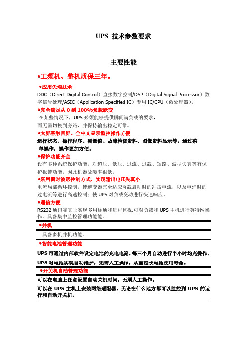
UPS 技术参数要求
主要性能
工频机、整机质保三年。
应用尖端技术
DDC(Direct Digital Control)直接数字控制/DSP(Digital Signal Processor)数字信号处理/ASIC(Application Specified IC)专用IC/CPU(微处理器)。
完全满足从0到100%负载跃变
在某些情况下,UPS必须能够提供瞬间满负载的要求,
而无需切换到旁路,并保持输出稳定可靠。
大屏幕触目屏、全中文显示监控操作方便
运行状态、操作程序、测量值、故障检修资料、图像资料显示等,通过菜
单操作,操作更加方便。
保护功能齐全
设有多种系统保护功能,对超压、低压、过流、过载、短路、波型失真等有保护报警功能,因此机器故障率很低。
采用瞬时波形控制方式,实现输出电压失真小
电流局部循环控制,使逆变器完全适应负载启动时的冲击电流,以及电涌时的过电流等进行高速控制;使UPS对负载变动进行快速响应。
通信方便
RS232通讯端真正实现多用途通和远程监视,可对负载和UPS主机进行英特网操作。
具备集中监控管理功能能。
并机
具备多机并机功能。
智能电池管理功能
UPS可通过内部软件设定电池的充电电流。
每三个月自动进行半小时均充操作。
UPS对电池实现自动维护,无需人工操作。
从而延长电池使用寿命。
开关机自动管理功能
可以在电脑上任意设置自动关机时间,无须人工操作。
可以在UPS主机上安装网络适配器,无论在什么地方都可以监控到UPS的运行和自动开关机。
技术参数。

TECUPS技术规格及要求交流静态不间断电源(UPS)装置,将被用来向仪表系统,火灾报警盘,电信系统等重要负荷提供不间断电源。
1.规范交流不间断电源应符合规格书及下列最新版法规、刊物及规范的要求。
1)国家标准和规范GB10963家用及类似场所用过电流保护断路器GB/T3859.1半导体变流器基本要求的规定GB/T4365电磁兼容术语(idtIEC60050-161)GB7260-2不间断电源设备(UPS)第2部分:电磁兼容性(EMC)要求GB/T7678半导体自换相变流器(IEC146-2)GB/T14549电能质量公用电网谐波2)国际标准IEC60076-1电力变压器第1部分:概述IEC60146半导体变流器IEC60478直流输出稳压电源IEC60686交流输出稳定电源IEC60896密固定式铅酸电池IEC60801工业过程测量与控制设备的电磁兼容要求JEC日本电气协会标准JEM日本电气制造协会标准NEC美国国家电气标准VDE德国电气协会标准DIN德国工业标准2.设计和结构1)使用条件交流不间断电源(UPS)应能在IEC60146-1-1规定的环境条件下工作。
UPS装于室内。
a本项目所在地的温度条件为:极端最高温度:42.6°C极端最低温度:-18.8°C平均相对湿度:67%地震设防烈度:6度海拔高度:1000m以下b电气使用条件根据IEC60146-23.1h条款的要求,在正常工作条件下的交流电源线电压为正弦波。
不间断电源(UPS)装置的额定值应以IEC60146-45.1条款中定义的电气使用条件为基础。
2)电气特性a在买方规定的输入输出电压和频率变化范围内,整流器应能正常地工作并提供连续的额定功率。
b在正常情况下,逆变器通过静态转换开关向重要负荷提供连续的交流电源,并向电池组提供所需要的最大电荷量。
cUPS应在逆变器及旁路侧同时配置有静态旁路开关,正常运行状态下逆变器侧静态开关导通,旁路侧静态开关断开。

在线式不间断电源UNINTERRUPTIBLE POWER SUPPLYPANPOWER User's Manual用户手册目录一、简介 (1)二、UPS工作原理方块图 (2)三、注意事项 (3)四、安装……………………………………………………………………………4-7动力连接.................................................................................5-6地线连接 (7)五、面板操作………………………………………………………………………8-125.1 LED状态指示 (8)5.2 按键操作…………………………………………………………………8-115.3 开/关机 (12)六、电脑监控………………………………………………………………………13-146.1 通讯线连接 (13)6.2 软件设置 (14)七、异常处理 (15)八、日常维护 (16)8.1 维护 (16)8.2 检查 (16)8.3 保修 (16)九、UPS技术规格 (17)十、UPS网络远程监控整体方案图 (18)十一、装箱清单 (18)一、简介1.CP系列UPS是真正在线式(TRUE ONLINE)不间断电源,隔离不稳定市电,如停电(BLOCKOUT)、杂讯(NOISE)、脉冲电压SPIKE&DIPS暂态过高电压(RTANSIENT)、低电压(BROWNOUT)高电压(OVERVOLTAGE)、电压突降或突升(SURGE—SAG)等电力问题,提供稳定的单相输出电源,是电脑及周边设备、程序控制系统、医疗设备、半导体厂设备、安全监视系统、化学工程设备、电台发射与接收系统、军用通讯、航空通讯系统及精密得要设备的最佳保护。
2.CP系列UPS采用20*2LCD模块及LED流程显示,可显示UPS规格、制造厂、序号、输入电压、输出电压、频率、电池电压、负载百分比、运转状态等,菜单式操作。
152For the latest on Altech Power Supply specifications please visit /power.CBI245A DC UPS Features:•Input: Single-phase 115 - 277 VAC •Output Load: power supply 24 VDC; 5 A •Output: Battery charging 24 VDC; 5 A •Suited for the following battery types:Open Lead Acid, Sealed Lead Acid, lead Gel and Ni-Cd (option)•Automatic diagnostic of battery status.•Switching technology, output voltage 22-28.8 VDC •Three charging levels: Boost, trickle and recovery •Protection degree IP20 - DIN rail mountableOUTPUT INPUTBATTERY OUTPUTLOADOUTPUT PROTECTION OTHERSCat. No.CBI245A Nominal Input Voltage 115 ~ 230 ~ 277 VAC Voltage range 90 – 305 VAC Inrush Current (V n – I n nom. Load). I 2t ≤11 A ≤ 5 msec Frequency 47 – 63 Hz Input Current (115 – 230 VAC) 2.8 ~ 1.3 A Internal fuse (factory replaceable) 4 A External Fuse (recommended) MCB curve B 10 A Output Voltage (V n ) / Nominal Current (I n )24 VDC / 5A Output Current I n 5 A Efficiency (at 50% of rated current)≥ 90 % Turn-On delay after applying input voltage 1 sec. (max) Start up with Strong Load (capacitive load) Yes, Unlimited Dissipation power load max 17 W Short-circuit protection Yes Over Load protection Yes Over Voltage Output protection Yes (typ. 35 VDC) Over Temperature protection Yes Output voltage (at I n ) 22 ~ 28.8 VDC Nominal current I load 1.1 x In A ± 5% Continuous current (without battery) I load = I n 5 A Continuous current (with battery) I load = I n + I batt 10 A Max. Current Output Load (Main) I load (4 sec.) 15 A max. Max. Current Output Load (Back Up) I load (4 sec.) 10 A max. Push Button or Remote Input Control (RTCONN cable) Start From Battery Without Main Time Buffering; min (switch output off without main input) ∞: standard 5 min.: Require SW Protection alarm against total discharge 19-20V DC battery Threshold alarm for battery almost flat 20-21 V DC battery Boost charge (25 °C) (at I n ) 28.8 VDC Max. time Bust Charge 15 h Min. time Bust Charge 1 min. Trickle charge (25 °C) (at I n ) 27.5 VDC Jumper Configuration battery type (V cell) Ni-Cd (optional) 2.23; 2.25; 2.27; 2.30; NiCd: 1.50 (20 elem.) Recovery Charge 2 ~ 16 VDC Charging current max I batt 5 A ± 5% Charging current limiting I adj 20 – 100 % / Ibatt Reverse battery protection Yes Sulfated battery check Yes by Jumper Detection of element in short circuit Yes Quiescent Current ≤ 5 mA Charging Curve automatic: I UoUo 3 stage Remote Input Control (RTCONN cable) Boost /Trickle / Recovery Ambient temperature (operation) -25 – +70°C De Rating Ta > 50°C - 2.5%(In) / °C Ambient temperature Storage -40 – +85°C Humidity at 25°C no condensation 95% Cooling Auto convention MTBF (IEC 61709)> 300.000 h153Altech Corp.®• 35 Royal Road • Flemington, NJ 08822-6000 • Phone (908)806-9400 • FAX (908)806-9490CBI245ADC UPSThe Altech DC-UPS system is built to optimize powermanagement. The available power is automatically allocated between load and battery, supplying power to the load is the firstpriority. For high inrush applications the charging power will reroute automatically to the load. In this case the maximum available current on the load output is two times the value of the device rated current.The Battery Care concept based on algorithms that achieve rapid and automatic charging, battery optimization during charging time, flat batteries recovery and real time diagnostic The Real Time Auto-diagnostic system, monitors battery faults, sulfated battery, short circuit battery elements, reverse polarity connection,battery disconnect. This conditions are detected and identified by the number of blinks of the diagnosis Led.The Altech DC-UPS system is designed to charge and monitor all battery types, by selecting the battery type via jumpers. Thepredefined curves include Open Lead Acid, Sealed Lead Acid, Gel,Ni-Cd (optional) battery types. The charging curve areprogrammed to automatically switch between Recovery Charge,Boost charge and Trickle charge. The continuous battery efficiencymonitoring, reduces battery damage risk and allows a safeoperation in permanent connection.A compact and rugged metal case with DIN rail mounting bracketprovide an easy installation and an IP20 protection.Voltage CurrentFast / Boost Charge Recovery Charge Tickle / Float Charge V o ltage /C u rrent Jumper for Battery Type SelectionSignal Output Contacts Main or Backup Power Yes Battery Power Low Yes Battery Fault Yes Max. Current Rating (Resistive Load)1A 30 VDC/60 VAC Minimum Permissible Current Rating 1mA @ 5 VDC RJ45 Connection Input/Output Temp. Comp. Battery (with ext. probe) Yes - Optional Remote monitoring display Yes - Optional Can Bus NoEnvironmentInsulation voltage (IN/OUT) 3000 VACInsulation voltage (input / ground) 1605 VAC Insulation voltage (Output / ground) 500 VAC Protection Class (EN/IEC 60529) IP20Pollution Degree Environment 2Connection TB, Screw Terminal 2,5 mm² (24–14AWG)Protection class (Ground Connected) Class I Dimensions (WxHxD) 65x115x135 mm 2.56x4.53x5.32 inWeight (approx.)0.6 kg (1.35 Lbs)Safety and EMC Battery charger standard compliance IEC/EN 60335-2-29Safety standards compliance:EN60950 / UL1950 / CEFire Detection and alarm compliance EN54-4 EMC Directive 89/336/EECCharging cycle DIN41773Emission IEC 61000-6-4Immunity IEC 61000-6-2。
不间断电源UPS的基本参数第一篇:不间断电源UPS的基本参数不间断电源UPS的基本参数UPS是(交流)不间断供电系统(Uninterruptable Power system)的缩写。
它分为动态和静态两种,动态UPS由旋转电机组成,而由电子元器件构成的UPS是静态的,一般所说的UPS多指静态UPS。
UPS主要用于敏感电子设备和不允许停电的场合,如计算机系统、生产线的过程控制、远距离通讯、医疗设备、飞机场、银行系统等。
UPS的基本参数(1)负载负载可分三类,10kV·A以下为小负载,10~60kV·A为中负载,60kV·A以上为大负载。
(2)输出电压的谐波含量(失真)谐波电压对电路中的参考电压及低电压工作的逻辑电路会造成噪声。
(3)非线性负载指电感性负载或电容性负载。
在计算机系统中,非线性负载主要是主机、打印机(特别是激光打印机)和显示终端等;线性负载主要是磁盘和磁带设各。
一般小负载是非线性负载;中负载是线性与非线性负载相近或其中一种稍大;而大负载一般是线性负载,因为大负载由多台设备构成,运行中此起彼伏,宏观看起来总负载比较稳定。
(4)阶跃负载当一部分负载接通或断开时,都会使负载产生阶跃变化。
由于UPS不能瞬时更正这种突然变化的电流9输出电压就会产生相应的变化。
小负载由于只接很少的设各,有时会出现100%的阶跃负载。
中等负载出现的阶跃不超过50%。
而大负载只有在不正常的运行状态下才可能出现超过z5%的阶跃负载。
一般的逆变器设计都能满足小于25%的阶跃负载。
(5)效率对于一个大系统来说,效率必须足够高。
比如一个125kV·A的UPS,若只有85%的效率,那么每年多消耗的费用相当于初始投资的30%。
(6)体积中小型UPS要求体积要尽可能小。
(7)噪声 UPS的噪声水平不应超过它所在环境要求的噪声水平。
第二篇:UPS不间断电源说到电源就不得不提一下UPS!什么是UPS?USP解释过来就是“不间断电源”的意思。
1/8DATA BRIEFINGJune 2002Complete data available on Data-on-Disc CD-ROM or at .µPSD3200FAMILYFlash Programmable System Devicewith 8032Microcontroller CoreFEATURES SUMMARYs The µPSD3200Family combines a Flash PSD architecture with an 8032microcontroller core The µPSD3200Family of Flash PSDs features dual banks of Flash memory,SRAM,general purpose I/O and programmable logic,supervi-sory functions and access via USB,I 2C,ADC,DDC and PWM channels,and an on-board 8032microcontroller core,with two UARTs,three 16-bit Timer/Counters and one External Interrupt.As with other Flash PSD families,the µPSD3200Family is also in-system program-mable (ISP)via a JTAG ISP interface.sLarge 8KByte SRAM with battery back-up optionsDual bank Flash memories–128KByte or 256KByte main Flash memory –32KByte secondary Flash memorysContent Security–Block access to Flash memorysProgrammable Decode PLD for flexible address mapping of all memories.s High-speed clock standard 8032core (12-cycle)s USB Interface (µPSD3234A-40U6only)s I 2C interface for peripheral connections s Five Pulse Width Modulator (PWM)channels s Standalone Display Data Channel (DDC)s Six I/O ports with up to 50I/O pins s 3000gate PLD with 16macrocells s Supervisor functionss In-System Programming (ISP)via JTAG s Zero-Power Technology sSingle Supply Voltage –4.5to 5.5V –3.0to 3.6VFigure 1.PackagesTQFP52(T)TQFP80(U)µPSD3200FAMILY2/8SUMMARY DESCRIPTION s Dual bank Flash memories–Concurrent operation,read from memory one while erasing and writing the other.In-Appli-cation Programming (IAP)for remote updates –Large 128KByte or 256KByte main Flash memory for application code,operating sys-tems,or bit maps for graphic user interfaces –Large 32KByte secondary Flash memory di-vided in small sectors.Eliminate external EE-PROM with software EEPROM emulation –Secondary Flash memory is large enough for sophisticated communication protocol (USB)during IAP while continuing critical system taskssLarge SRAM with battery back-up option –8KByte SRAM for RTOS,high-level languag-es,communication buffers,and stackssProgrammable Decode PLD for flexible address mapping of all memories–Place individual Flash and SRAM sectors on any address boundary –Built-in page register breaks restrictive 8032limit of 64KByte address space –Special register swaps Flash memory seg-ments between 8032“program”space and “data”space for efficient In-Application Pro-grammingsHigh-speed clock standard 8032core (12-cycle)–40MHz operation at 5V,24MHz at 3.3V –Two UARTs with independent baud rate,three 16-bit Timer/Counters and two External InterruptssUSB Interface (µPSD3234A-40U6only)–Supports USB 1.1Slow Mode (1.5Mbit/s)–Control endpoint 0and interrupt endpoints 1and 2sI 2C interface for peripheral connections –Capable of master or slave operation sFive Pulse Width Modulator (PWM)channels –Four 8-bit PWM units–One 16-bit PWM unitsStandalone Display Data Channel (DDC)–For use in monitor,projector,and TV applica-tions –Compliant with VESA standards DDC1and DDC2B –Eliminate external DDC PROM s Six I/O ports with up to 50I/O pins–Multifunction I/O:GPIO,DDC,I 2C,PWM,PLD I/O,supervisor,and JTAG –Eliminates need for external latches and logics3000gate PLD with 16macrocells–Create glue logic,state machines,delays,etc.–Eliminate external PALs,PLDs,and 74HCxx –Simple PSDsoft Express software ...FreesSupervisor functions–Generates reset upon low voltage or watch-dog time-out.Eliminate external supervisor device –Reset In pinsIn-System Programming (ISP)via JTAG –Program entire chip in 10-25seconds with no involvement of 8032–Allows efficient manufacturing,easy product testing,and Just-In-Time inventory –Eliminate sockets and pre-programmed parts –Program with FlashLINK TM cable and any PCsContent Security–Programmable Security Bit blocks access of device programmers and readerssZero-Power Technology–Memories and PLD automatically reach standby current between input changessPackages –52-pin TQFP–80-pin TQFP:allows access to 8032address/data/control signals for connecting to external peripherals3/8µPSD3200FAMILYFigure 2.µPSD3200Family Functional ModulesAI066194Channel ADC1Mb or 2Mb Main FlashDecode PLD64Kb SRAMCPLD -16MACROCELLSJTAG ISP Port 1Port 32UARTS Interrupt3Timer /Counters256Byte SRAM8051Core Port 3,UART,Intr,Timers,I2CPSD Internal Bus8032Internal BusUSB &TransceiverPort 1,Timers and 2nd UART and ADCDDC w/256Byte SRAM PWM 5Channels Port 4PWM and DDCDedicated USB PinsPort A &B,PLD I/O and GPIOPort D GPIO Port C,JTAG,PLD I/O and GPIOVCC,GND,XTAL256Kb Secondary FlashDedicated PinsI2CPort 0,2Ext.BusReset LogicLVD &WDTBus InterfaceResetD0-D7A0-A15RD,PSEN WR,ALEPage Register PSD MODULEMCU MODULEµPSD3200FAMILY4/8Table 1.80-Pin Package Pin DescriptionNote:PSD Port A and MCU Address/Data bus are added for 80-pin deviceSignal Name In/Out FunctionBasicAlternateAD7-AD0I/O Multiplexed Address/Data bus A11-A8I/O External Address BusRxD2-RxD1I/O General I/O port pinsUART Receive TxD2-TxD1I/O UART TransmitINT1-INT0I/O Interrupt inputs /timer gate controls T2-T0I/O Counter inputsSDA1-SDA2I/OI 2C Bus serial data I/O /DDC interface SCL1-SCL2I/O I 2C Bus clock I/OVSYNC I/O VSYNC input for DDC interface T2EX I/O Timer 2Trigger input ADC3-ADC0I/O ADC Channels inputPWM4-PWM0I/O 8-bit Pulse Width Modulation outputsUSB-,USB+I/O USB I/OAVREF O Reference Voltage input for ADC RD_O Read signal,external bus WR_O Write signal,external bus PSEN_O PSEN signal,external bus ALE O Address Latch signal,external bus RESET_I Active low reset inputXTAL1I Oscillator input pin for system clock XTAL2OOscillator output pin for system clockPA7-P A0I/O General I/O port pins1.PLD Macro-cell outputs2.PLD inputstched Address Out (A0-A7)4.Peripheral I/O mode PB7-PB0I/O General I/O port pins1.PLD Macro-cell outputs2.PLD inputstched Address Out (A0-A7)PC7-PC0I/O General I/O port pins1.PLD Macro-cell outputs2.PLD inputs3.SRAM stand by voltage input (VSTBY)4.JTAG Interface (TDI,TDO,TMS,TCK,TSTA T,TERR)5.SRAM battery-on indicator (PC4)PD2-PD1I/O General I/O port pin1.PLD I/O2.Clock input to PLD and APD3.Chip select to PSD ModuleµPSD3200FAMILY Figure3.TQFP52ConnectionsNote:NC=Not ConnectedPU=Pull-up resistor required(2kΩfor3V devices,7.5kΩfor5V devices)39P1.5/ADC1 38P1.4/ADC0 37P1.3/TXD1 36P1.2/RXD1 35P1.1/T2X 34P1.0/T233V CC32XTAL231XTAL130P3.7/SCL1 29P3.6/SDA1 28P3.5/T127P3.4/T0PD1 PC7 PC6 PC5 PU PC4 NC V CC GND PC3 PC2 PC1 PC0 12345678910111213525154948474645444342414PBPB1PB2PB3PB4PB5VREFGNDRST-INPB6PB7ADC3ADC21415161718192212223242526P4.7/PWM4P4.6/PWM3P4.5/PWM2P4.4/PWM1P4.3/PWMGNDP4.2/DDCVSYNCP4.1/DDCSCLP4./DDCSDAP3./RXDP3.1/TXDP3.2/EXINTP3.3/EXINT1AI05790B5/8µPSD3200FAMILY6/8Figure 4.TQFP80ConnectionsNote: 1.NC =Not ConnectedB-needs a pull-up resistor (see the description of the USB function)60P1.5/ADC1 59P1.4/ADC0 58P1.3/TXD1 57P2.3,A11 56P1.2/RXD1 55P2.2,A10 54P1.1/T2X 53P2.1,A9 52P1.0/T2 51P2.0,A8 50V CC 49XTAL2 48XTAL1 47P0.7,AD7 46P3.7/SCL1 45P0.6,AD6 44P3.6/SDA1 43P0.5,AD5 42P3.5/T1 41P0.4,AD4PD2 P3.3/EXINT1 PD1 PD0,ALE PC7 PC6 PC5 USB- PC4 USB+ NC V CC GND PC3 PC2 PC1 NC P4.7/PWM4 P4.6/PWM3 PC0123 45 6 7 8 9 10 11 12 13 14 15 16 1718 192080 79 78 77 76 75 74 73 72 71 70 69 68 67 66 65 64 63 62 61P B 0P 3.2/E X I N T 0P B 1P 3.1/T X DP B 2P 3.0/R X DP B 3P B 4P B 5N CV R E FG N DR E S E T -I NP B 6P B 7R D ,C N T L 1P 1.7/A D C 3P S E N ,C N T L 2W R ,C N T L 0P 1.6/A D C 22122232425262728293031323334353637383940P A 7 P A 6 P 4.5/P W M 2 P A 5 P 4.4/P W M 1 P A 4 P 4.3/P W M 0 P A 3 G N D P 4.2/D C C V S Y N C P 4.1/D D C S C L P A 2 P 4.0/D D C S D A P A 1 P A 0 A D 0,P 0.0 A D 1,P 0.1 A D 2,P 0.2 A D 3,P 0.3 P 3.4/T 0AI05791µPSD3200FAMILY PART NUMBERINGTable2.Ordering Information SchemeFor a list of available options(speed,package, etc.)or for further information on any aspect of this device,please contact your nearest ST Sales Of-fice.Example:uPSD3234B V–24U6TDevice TypeuPSD=Microcontroller PSDFamily3=8032corePLD Size2=16Macrocells3=32MacrocellsSRAM Size1=16Kbit3=64Kbit5=256KbitMain Flash Memory Size3=1Mbit4=2Mbit5=4MbitIP MixA=USB,I2C,PWM,DDC,ADC,(2)UARTsSupervisor(Reset Out,Reset In,LVD,WD)B=I2C,PWM,DDC,ADC,(2)UARTsSupervisor(Reset Out,Reset In,LVD,WD)Operating Voltageblank=V CC=4.5to5.5VV=V CC=3.0to3.6VSpeed24=24MHz40=40MHzPackageT=52-pin TQFPU=80-pin TQFPTemperature Range1=0to70°C(commercial)6=–40to85°C(industrial)OptionT=Tape&Reel Packing7/8µPSD3200FAMILYInformation furnished is believed to be accurate and reliable.However,STMicroelectronics assumes no responsibility for the consequences of use of such information nor for any infringement of patents or other rights of third parties which may result from its use.No license is granted by implication or otherwise under any patent or patent rights of STMicroelectronics.Specifications mentioned in this publication are subject to change without notice.This publication supersedes and replaces all information previously supplied.STMicroelectronics products are not authorized for use as critical components in life support devices or systems without express written approval of STMicroelectronics.The ST logo is registered trademark of STMicroelectronicsAll other names are the property of their respective owners©2002STMicroelectronics-All Rights ReservedSTMicroelectronics group of companiesAustralia-Brazil-Canada-China-Finland-France-Germany-Hong Kong-India-Israel-Italy-Japan-Malaysia-Malta-Morocco-Singapore-Spain-Sweden-Switzerland-United Kingdom-United States.8/8。