NE210.031AXA1中文资料
- 格式:pdf
- 大小:411.05 KB
- 文档页数:2

尼凯恩NX(neken NX)联通版终端参数
上行峰值: 11.标准配置:单电单充、数据线、耳机
外观:直板
颜色:白色
尺寸/体积:141.7*70.5*9.75mm 重量:176g
屏幕参数:5.0英寸、1920×1080、1677万色、电容触摸屏
网络频率:GSM 5Mbps
下行峰值:42Mbps
基带芯片型号、架构及主频: MTK MT6589T Cortex-A7四核
1.5GHz
操作系统:阿里云OS 2.0.1
AP芯片型号、架构及主频:芯片同上
SIM卡类型:双卡均为2FF
摄像头:1300万像素AF 副摄像头:500万像素AF
重力感应:支持 NFC:不支持
WIFI/WAPI:支持
GPS:支持FM:支持
蓝牙:支持
RAM:1GB
ROM: 16GB
用户可用内置存储:10.71GB 扩展存储卡:最大可支持到32GB
电池容量:2000mAh;( 3G:待机:160小时;通话:2.8小
时;2G:待机:200小时;通话:3.5小时)
预装联通业务:联通3G互联网沃门户、沃商店、116114、
手机邮箱、手机营业厅、USIM卡应用
第三方业务:应用中心、高德地图、淘宝、淘宝彩票、聚划
算、天猫、淘宝旅行、塔读文学、淘宝读书、支付宝钱包等
特色功能:阿里云系统。

Valid to 31‐01‐16DescriptionIridium Hardware$1,396.28 IR‐00‐AHKT1301Iridium GO! Global Communciations Device ‐ CONTACT YOUR ACCOUNT MANAGERFOR SPECIAL PRICINGc/w AC Travel Adapter, international plug kit, DC travel adapter, rechargeable Li‐ionbattery,protective cover, micro USB cable, user guide, legal guide, GEOS brochureIR‐00‐CPKT1101Iridium 9575 Portable Satellite Telephone ‐ CONTACT YOUR ACCOUNT MANAGER FOR$2,345.77 SPECIAL PRICINGc/w AC Travel Charger and International Plug, Rechargeable LI‐Ion Battery, Data CD,Adapter 9575 Power USBAdapter 9575 Antenna Power USB, Portable Auxiliary Antenna, Auto Accessory Adapter,Leather Holster,USB to Mini USB Cable, Hands Free Headset, Quick Start Guide and User GuideIR‐00‐BPKT0801Iridium 9555 Portable Satellite Telephone ‐ CONTACT YOUR ACCOUNT MANAGER FOR$1,898.95 SPECIAL PRICINGc/w AC Travel Charger and International Plug, Rechargeable LI‐Ion Battery, Data CD,Antenna Adapter, Portable Auxiliary Antenna, Auto Accessory Adapter, Holster,USB to Mini USB Cable, Hands Free Headset, Quick Start Guide and User GuideIR‐00‐MOCKGO!Dummy 9560 Iridium GO! Unit$122.87 IR‐00‐MOCK9575Dummy 9575 Handset$134.04 IR‐00‐MOCK9555Dummy 9555 Handset$100.53 IR‐00‐APKT0401 Iridium 9505A Portable Satellite Phone ‐ US Made Non‐RoHS$2,989.14 c/w AC Travel Charger and International Plug, Rechargeable LI‐Ion Battery,Antenna Adapter, Portable Auxiliary Antenna, Auto Accessory AdapterLeather Holster, Lanyard, Hands Free Headset and User GuideIR‐00‐SBD3D1201‐9603Iridium 9603 Transceiver & Developers Kit$4,026.52 IR‐00‐SBD1201‐9603‐1Iridium 9603 Transceiver & Developers Kit (10+)$2,558.02 IR‐00‐SBD3M1201‐9603Iridium 9603 Transceiver$738.19 IR‐00‐100724 Iridium 9602 Transceiver & Developers Kit$3,737.76 IR‐00‐SDB2M1001Iridium 9602 Transceiver$622.96 IR‐00‐102158Iridium 9522B LBT Tranceiver$2,118.06 IR‐01‐102167Iridium 9522B Accessory Kit$87.21IR‐00‐CLBT1101‐9523Iridium 9523 Core$2,684.34 IR‐00‐LBTDT1101‐9523Iridium 9523 Development & Transceiver Kit$4,026.52 Iridum Go! CablesIR‐01‐GO‐ADAPTCABLE Iridium Go! Adaptor Cable (ex Thailand)$25.00 IR‐01‐W5USB1301Outdoor cable 5M usb‐a to MicroUSB plug$95.77 IR‐01‐WBAT13019560 Battery 3500mAh$134.05 IR‐01‐WBKT1301Bracket Kit ‐ wall mount for 9560$79.82 IR‐01‐WCCS1301Carry Bag with karabiner for 9560 ‐ bagged$70.24 IR‐01‐WACTC1301AC Charger, USB 5V 2.1A, Black, 4 region plugs, Boxed$92.58 IR‐01‐WAUT1301Auto Adaptor, Cig‐lighter plug to USB$35.13 IR‐01‐WCVR13019560 Protective Cover (uses BEA_018_130) with polybag$35.13 IR‐01‐WMUSB1301Cable USB 1.2m USB‐A plug to microUSB plug, thick gauge$22.34 Standard Accessories for 9575 & 9555 Portable PhoneIR‐01‐PHS300IC Iridium AxcessPoint WiFi$325.47 IR‐01‐USBC0801USB‐Mini USB Cable ‐ 9555$65.77 Standard Accessories for 9575 Portable PhoneIR‐01‐BAT31001Rechargeable Li‐ion Battery ‐ 9575$213.70 IR‐01‐H3AA1101Adapter, 9575 Antenna, Power USB$263.03 IR‐01‐H3APU1101Adapter, 9575, Power USB$230.13 IR‐01‐H3HOL1101Leather Holster ‐ 9575$82.19 IR‐01‐H3QS1101Quick Start Guide – printable copies available via IR‐01‐H3UG1101User Guide ‐ 9575$39.46 IR‐01‐H3CD1101Data CD ‐ 9575$13.15 Standard Accessories for 9555 Portable PhoneIR‐01‐BAT41101Rechargeable Hi Capacity Li‐ion Battery ‐ 9555$295.90 IR‐01‐H2UG1002User Guide ‐ 9555 (& 9575)$39.46 IR‐01‐USBC0801USB‐Mini USB Cable ‐ 9555$65.77 IR‐01‐ H2AA0801Antenna Adapter ‐ 9555$115.06 IR‐01‐HOL0801Leather Holster ‐ 9555$82.19 IR‐01‐BAT21101Rechargeable Li‐ion Battery ‐ 9555$197.26 IR‐01‐H2CD0801Data CD ‐ 9555$13.15 PEL‐01‐1300Peli case for 9555$166.37 Standard Accessories for 9575, 9555 & 9505A Portable PhoneIR‐01‐ACTC0701AC Travel Charger $180.83 IR‐01‐IPK0601International Plug Kit $65.77 IR‐01‐AUT0901Auto Accessory Adapter $115.06 IR‐01‐PAA0601Portable Auxiliary Antenna$246.58 IR‐01‐HFHS0601Hands Free Headset, Retractable$36.17 Standard Accessories for 9505A Portable PhoneIR‐01‐RDA0401RS‐232 Adapter for Data Kit ‐ 9505A$164.38 IR‐01‐ADKT0602Data Kit ‐ 9505A$276.15 IR‐01‐PUG0602User Guide ‐ 9505A$39.46 IR‐01‐BAT0602Rechargeable Li‐ion Battery 2800 mAh ‐ 9505A$197.26Standard Accessories for SS9500, SS9505 and 9505A Portable PhonesIR‐01‐AAA0601Auxiliary Antenna Adapter$115.06 IR‐01‐DCD06002CD‐ROM$13.15 Standard Accessories for both SS9505 and 9505A Portable PhonesIR‐01‐SYN7863A Leather Holster for 9505$82.19 IR‐01‐ANT0501Replacement Antenna ‐ 9505/9505A$443.83 Standard Accessories for both SS9500 and SS9505 Portable PhonesIR‐01‐ACDC0601AC/DC Converter ‐ 9500/9505$147.96 IR‐01‐SYN7024A International Plug Kit$65.77 IR‐01‐SYN0039B Auto Accessory Adapter ‐ 9500/9505$115.06 IR‐01‐SYN0060C High Capacity Battery ‐ 9500/9505 $197.26 IR‐01‐SYN8371B Data Kit c/w Data Cable, Tripod Bracket & CD‐ROM ‐ 9505$276.15 IR‐01‐SYN0091A RS‐232 Adapter for Data Kit ‐ 9505 ‐ Whilst Stocks Last$164.38 Iridium SIM CardsIR‐01‐SIM SDL Iridium SIM Card (Includes Activation)IR‐01‐SIM 325 SDL Iridium SIM Card ‐ 325 for Pre‐Paid ServiceIR‐01‐SIM 318 SDL Iridium SIM Card ‐ 318 for Crew Calling Service。

441243GU (General Use) TypeSOP Series1- Channel (Form A) 4-Pin Typemm inch4.4±0.2.173±.0082.1±0.2.083±.0084.3±0.2.169±.008FEATURES1. SO package 4-Pin type in super min-iature designThe device comes in a super-miniature SO package 4-Pin type measuring(W)4.3 × (L)4.4 × (H)2.1 mm (W).169 × (L).173 × (H).083 inch —approx. 70% of the volume and 70% of the footprint size of SO package 6-pin type PhotoMOS Re-lays.2. Tape and reelThe device comes standard in a tape and reel (1,000 pcs./reel) to facilitate automat-ic insertion machines.Volume(4-pin)(6-pin)Approx. 70%FootprintApprox. 70%3. Controls low-level analog signals PhotoMOS relays feature extremely low closed-circuit offset voltage to enable control of low-level analog signals without distortion.4. Low-level off state leakage current In contrast to the SSR with an off state leakage current of several milliamps, the PhotoMOS relay features a very small off state leakage current of only 100 pA (AQY214S) even with the rated load volt-age of 400 V .TYPICAL APPLICATIONS• T elecommunications (PC, Electoronic Notepad)• Measuring and T esting equipment • Factory Automation Equipment • Security equipment• High speed inspection machinesTYPESAC/DC type* Indicate the peak AC and DC values.(1)Tape package is the standard packing style. Also available in tube. (Part No. suffix "X" or "Z" is not needed when ordering; T ube: 100 pcs.;Case: 2,000 pcs.)(2)For space reasons, the top two letters of the product number "AQY" and "S" are omitted on the product seal. The package type indicator "X"and "Z" are omitted from the seal. (Ex. the label for product number AQY210S is 210).Output rating*Part No.Packing quantity in tapeand reelLoad voltageLoad current Picked from the 1/2-pin side Picked from the 3/4-pin side350 V 120 mA AQY210SX AQY210SZ 1,000 pcs.400 V100 mAAQY214SX AQY214SZRATINGAC/DC type1. Absolute maximum ratings (Ambient temperature: 25 ° C 77 ° F )ItemSymbol AQY210SAQY214SRemarksInputLED forward current I F 50 mA LED reverse voltageV R 3 V Peak forward current I FP 1 A f = 100 Hz, Duty factor = 0.1%Power dissipationP in 75 mWOutputLoad voltage (peak AC)V L 350 V 400 V Continuous load current (peak AC)I L 0.12 A 0.1 A Peak load current I peak 0.3 A0.24 A 100ms (1 shot), V L = DCPower dissipationP out 300 mW T otal power dissipation P T 350 mW I/O isolation voltageV iso 1,500 V ACT emperture limitsOperatingTopr –40 ° C to +85 ° C –40 ° F to +185 ° F Non-condensing at low temperaturesStorageTstg–40 ° C to +100 ° C –40 ° F to +212 °FPhotoMOS RELAYS查询AQY210供应商捷多邦,专业PCB打样工厂,24小时加急出货AQY21 r S452. Electrical characteristics (Ambient temperature: 25 ° C 77 ° F )Note: Recommendable LED forward current IF = 5mA. For type of connection, see page 31.*Turn on/T urn off times For Dimensions, see Page 28.s For Schematic and Wiring Diagrams, see Page 31. s For Cautions for Use, see Page 36.ItemSymbol AQY210SAQY214SRemarks InputLED operate currentTypical I Fon 0.9 mA I L = Max.Maximum 3 mA LED turn off current Minimum I Foff 0.4 mA I L = Max.Typical 0.85 mALED dropout voltage Typical V F1.14 V (1.25 V at IF = 50 mA)I F = 5 mA Maximum 1.5 V OutputOn resistanceTypical Ron17 Ω 25 Ω I F = 5 mA IL = Max.Within 1 s on time Maximum 25 Ω35 ΩOff state leakage current Maximum ILeak 1 µ AI F = 0I L = Max.TransfercharacteristicsTurn on time*T ypical T on 0.23 ms0.21 ms I F = 5 mAI L = Max.Maximum 0.5 ms Turn off time*Typical T off 0.04 ms I F = 5 mA I L = Max.Maximum 0.2 ms I/O capacitanceMaximum C iso1.5 pF f = 1 MHz V B = 0Initial I/O isolation resistanceMinimumRiso1,000 M Ω500 V DCInputOutput10%90%REFERENCE DATA1. Load current vs. ambient temperature char-acteristicsAllowable ambient temperature:–40 ° C to +85 ° C–40 ° F to +185 ° F2. On resistance vs. ambient temperature char-acteristicsMeasured portion: between terminals 3 and 4;LED current: 5 mA; Load voltage: Max. (DC);Continuous load current: Max. (DC)3. T urn on time vs. ambient temperature char-acteristicsLED current: 5 mA; Load voltage: Max. (DC);Continuous load current: Max. (DC)60801001202040Ambient temperature, °C L o a d c u r r e n t , m A 01020304050Ambient temperature, °CO n r e s i s t a n c e , Ω1.01.52.50.52.03.0Ambient temperature, °CT u r n o n t i m e , m sAQY21 r S4. Turn off time vs. ambient temperature char-acteristicsLED current: 5 mA; Load voltage: Max. (DC);Continuous load current: Max. (DC)5. LED operate current vs. ambient tempera-ture characteristicsSample: All types; Load voltage: Max. (DC);Continuous load current: Max. (DC)6. LED turn off current vs. ambient temperature characteristicsSample: All types; Load voltage: Max. (DC);Continuous load current: Max. (DC)Ambient temperature, °C T u r n o f f t i m e , m s1234–4050–202040608085Ambient temperature, °C L E D o p e r a t e c u r r e n t , m A1234–4050–202040608085Ambient temperature, °CL E D t u r n o f f c u r r e n t , m A。
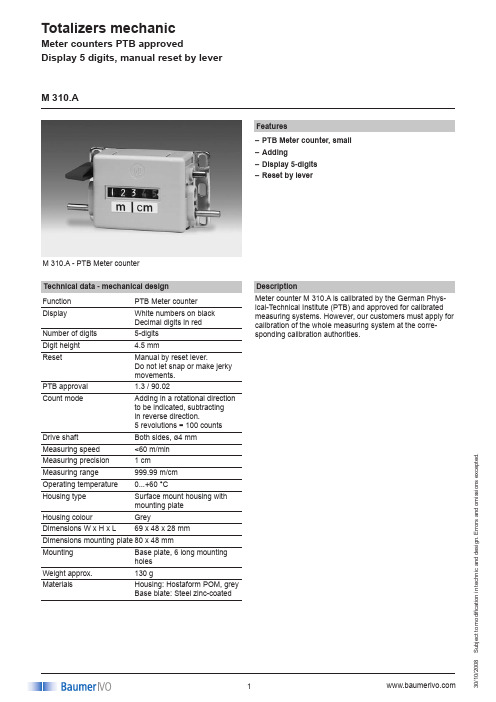
Totalizers mechanicS u b j e c t t o m o d i fi c a t i o n i n t e c h n i c a n d d e s i g n . E r r o r s a n d o m i s s i o n s e x c e p t e d .008M 310.A - PTB Meter counter FeaturesPTB Meter counter, small –Adding –Display 5-digits –Reset by lever–M 310.ATechnical data - mechanical design Function PTB Meter counter DisplayWhite numbers on black Decimal digits in red Number of digits 5-digits Digit height 4.5 mmResetManual by reset lever.Do not let snap or make jerky movements.PTB approval 1.3 / 90.02Count modeAdding in a rotational direction to be indicated, subtracting in reverse direction.5 revolutions = 100 counts Drive shaft Both sides, ø4 mm Measuring speed <60 m/minMeasuring precision 1 cm Measuring range 999.99 m/cm Operating temperature 0...+60 °CHousing type Surface mount housing with mounting plate Housing colour GreyDimensions W x H x L 69 x 48 x 28 mmDimensions mounting plate 80 x 48 mmMounting Base plate, 6 long mounting holes Weight approx.130 gMaterialsHousing: Hostaform POM, grey Base blate: Steel zinc-coatedMeter counters PTB approvedDisplay 5 digits, manual reset by leverMeter counter M 310.A is calibrated by the German Phys-ical-Technical Institute (PTB) and approved for calibrated measuring systems. However, our customers must apply for calibration of the whole measuring system at the corre-sponding calibration authorities.DescriptionTotalizers mechanicS u b j e c t t o m o d i fi c a t i o n i n t e c h n i c a n d d e s i g n . E r r o r s a n d o m i s s i o n s e x c e p t e d .008M 310.APart number M 310.A0Display / direction of rotation15-digits 999.99 m, 5 revolutions= 100 digits / direction I25-digits 999.99 m, 5 revolutions= 100 digits / direction IIMeter counters PTB approvedDisplay 5 digits, manual reset by leverAway from user Towards userSense of rotation I Sense of rotation IIDirection of strokes and rotationDimensionsAccessoriesMeasuring wheels (page %S)MR211.04A Circumf. 20 cm, knurled aluminium MR241.04D Circumf. 20 cm, smooth Hytrel TPE-E MR261.04A Circumf. 20 cm, knopped rubber NBR Nitril MR291.04D Circumf. 20 cm, grooved Hytrel TPE-E。

NewStar210A 中频信号采样器是东方联星针对GPS/GNSS 接收机前端工作过程设计研发的产品,具有体积小,功耗低,易于使用等优点。
特有的GPS 中频数据回放功能,为GPS 接收机开发、调试提供稳定、可靠、可重复使用的信号源,起到了GPS 信号发生器的部分作用。
数字回放式GPS 中频信号采样器NS210A 开放GPS 原始数据格式,开放GPS 信号处理源代码主要用途:◆ 软件GPS 接收机设计开发◆ GPS 芯片和接收机设计◆ GPS 干扰、抗干扰研究◆ GPS 载波相位研究与应用研究◆ 多径干扰研究◆ GPS 信号谱分析◆ 高灵敏度GPS 搜索与跟踪算法研究◆ 高精度GPS 接收机算法研究工作原理:NS210A 接收GPS L1信号,下变频,生成2比特数据流,通过USB 接口送给PC 机,在PC 机上设计实现GPS 核心算法和软件。
独特的2比特GPS 中频数据回放能力,为GPS 接收机开发、调试提供稳定、可靠、可重复使用的信号源。
NS210A 同时提供Matlab 源程序包括GPS CDMA 信号相关搜索、C/A 码相位测量、卫星Doppler 频移测量、频谱分析、三维图形界面等功能。
系统组成:◆ NewStar210A GPS中频信号采样单元 ◆ USB2.0接口◆ GPS L1天线◆ NewStar210A安装使用手册,技术参考手册,质量检验合格证,质量保证单,装箱单,安装光盘。
◆接收信号:G P S L1频率(1575.42MHz)◆测距码:C/A码◆信号带宽:2.4MHz◆采样频率:16MHz◆采样宽度:2比特◆计算机接口:USB2.0码相关相关峰主要技术指标:频谱分析。

P/N: 1802041000302*1802041000302*NE-4100 Series Quick Installation GuideVersion 5.1, December 2019Technical Support Contact Information /support Moxa Americas:Toll-free: 1-888-669-2872Tel: 1-714-528-6777Fax: 1-714-528-6778 Moxa China (Shanghai office): Toll-free: 800-820-5036 Tel: +86-21-5258-9955 Fax: +86-21-5258-5505 Moxa Europe:Tel: +49-89-3 70 03 99-0Fax: +49-89-3 70 03 99-99 Moxa Asia-Pacific: Tel: +886-2-8919-1230 Fax: +886-2-8919-1231 Moxa India:Tel: +91-80-4172-9088Fax: +91-80-4132-10452019 Moxa Inc. All rights reserved.OverviewThe MOXA NE-4100 Series of Network Enablers are serial-to-Ethernet embedded modules that come in 3 types: drop-in type (NE-4100T), RJ45 type (NE-4110S/A), and pin-header type (NE-4120S/A). MOXA provides a Starter Kit for each NE-4100 series module. Each Starter Kit contains an evaluation board that can be used to evaluate the modules and to develop applications. The following table lists the model names of all NE-4100 Series modules, along with the model names of the corresponding Starter Kits.Starter Kit Model NamesNE-4100 Series Model Names Standard ProgrammableNE-4100-ST NE-4100T NE-4100T-PNE-4110-ST NE-4110S NE-4110S-P NE-4110A NE-4110A-PNE-4120-ST NE-4120S NE-4120S-P NE-4120A NE-4120A-PPackage ChecklistEach NE-4100 series starter kit package contains the following items: • 1 NE-4100 series evaluation board• 1 universal power adaptor• 2 power cords• 1 null modem serial cable• 1 cross-over Ethernet cable• 1 quick installation guide (printed)• 1 warranty cardNotify your sales representative if any of the above items is missing or damaged.Hardware Installation ProcedureFollow these steps to prepare the module and evaluation board for testing and application development.STEP 1: Plug the NE-4100 module into the sockets on the top of the evaluation board.NE-4100-ST:After attaching the module to the evaluation board, the triangles on the module and evaluation board should line up.NE-4100-ST Starter KitNE-4110-ST:The module and evaluation board have two jumper arrays, each with a pin labeled 1. Be sure to connect the correct Pin 1 on the module to the correct Pin 1 on the evaluation board.NE-4110-ST Starter KitNE-4120-ST:The module and evaluation board have two jumper arrays, each with a pin labeled 1. Be sure to connect the correct Pin 1 on the module to the correct Pin 1 on the evaluation board.NE-4120-ST Starter KitNOTE For detailed information about the pin assignments, wiring, LED indicators, and board layouts, refer to Chapter 2 of the NE-4100 Series User’s Manual.STEP 2: Connect the 12 VDC power line with the evaluation board’s power jack.STEP 3: Use an RJ45 Ethernet cable to connect the NE evaluation board plus module to an Ethernet network. Note that for NE-4100T and NE-4120, the RJ45 Ethernet port is located on theevaluation board. For NE-4110, the RJ45 Ethernet port islocated on the module itself.STEP 4: Use the serial data cable to connect the evaluation board to a serial device.STEP 5: For NE-4110-ST and NE-4120-ST, use jumper JP2 on the evaluation board to select the proper serial interface. Seepages 3-6 and 3-7 of the NE-4100 Series User’s Manual fordetails.Software Utility Installation ProcedureNE-4100 ModuleSoftware Installation1.Start the “Network Enabler Administrator” setup program to beginthe installation. When the Welcome window opens, click on Next.2.When the Select Additional Tasks window opens, click on Next.3.Click on Install to install program files in the default directory.4.The Installing window reports the progress of the installation.5.Click on Finish to complete the installation.Module Configuration1.Start the “Network Enabler Administrator” program.2.Click on Configuration from the menu bar, and then selectBroadcast Search from the drop-down menu.3.After the search is finished, all NE-4100 modules that were foundwill be shown in the right panel of the Configuration window. Ifyou locate more than one module connected to this network, refer to the MAC address on the module(s) to determine which modules are the ones you wish to configure.4.Refer to pages 7-6 to 7-19 of the NE-4100 Series User’s Manualfor additional configuration instructions.NE-4100 Programmable ModuleSoftware Installation1.Start the “Network Enabler SDK” setup program to begin theinstallation. When the Welcome window opens, click on Next. 2.Select the target directory, and then click on Next when theSelect Destination Directory window opens.3.Click on Next when the Select Additional Tasks window opens.4.Click on Install. The Installing window will report the progress ofthe installation.5.Click on Finish to complete the installation.Module Configuration1.Start the “NE SDK Manager” program.2.Click on Search from the menu bar, and then select BroadcastSearch from the drop-down menu.3.After the search is finished, all NE-4100-P modules that werefound will be shown in the NE SDK Manager window. Refer to the “Network Enabler SDK 2 Programmer’s Guide” for additionalinformation about setting environment variables and developingapplications with NE-4100-P Series products.Reference MaterialThe following detailed user’s guides can be downloaded from Moxa’s product page under the NE-4100 Series’ product page.NE-4100 Standard Module•NE-4100 Series User’s ManualNE-4100-P Series•Network Enabler SDK 2 Programmer’s Guide•Network Enabler SDK 2 API Reference。
关于适配210大电流组件的说明下载提示:该文档是本店铺精心编制而成的,希望大家下载后,能够帮助大家解决实际问题。
文档下载后可定制修改,请根据实际需要进行调整和使用,谢谢!本店铺为大家提供各种类型的实用资料,如教育随笔、日记赏析、句子摘抄、古诗大全、经典美文、话题作文、工作总结、词语解析、文案摘录、其他资料等等,想了解不同资料格式和写法,敬请关注!Download tips: This document is carefully compiled by this editor. I hope that after you download it, it can help you solve practical problems. The document can be customized and modified after downloading, please adjust and use it according to actual needs, thank you! In addition, this shop provides you with various types of practical materials, such as educational essays, diary appreciation, sentence excerpts, ancient poems, classic articles, topic composition, work summary, word parsing, copy excerpts, other materials and so on, want to know different data formats and writing methods, please pay attention!关于适配210大电流组件的说明概述在现代科技发展的浪潮下,电力领域的需求日益增长。
专利名称:视频、音频数据记录和重放设备专利类型:发明专利
发明人:小黑正树
申请号:CN200310120417.3
申请日:20031211
公开号:CN1530958A
公开日:
20040922
专利内容由知识产权出版社提供
摘要:一种视频、音频数据记录和重放设备,包括:具有控制单元、数字记录媒体和电池的机身;提供在机身侧面的摄像机单元;可相对于机身活动的显示单元;和音频数据处理单元;控制单元和用作主数据记录媒体的微型硬盘驱动器,将设备中提供的各种产品单元的特征连系起来,从而提供微型的便携式视频、音频数据记录和重放设备,实现各种功能,这些产品单元例如数字摄像机、数字照相机、MP3播送器和录音机。
申请人:三星电子株式会社
地址:韩国京畿道
国籍:KR
代理机构:中科专利商标代理有限责任公司
代理人:戎志敏
更多信息请下载全文后查看。
iTN2100 智能专线接入平台iTN2100-12产品概述随着业务多元化发展,不同客户、不同业务之间差异化服务指标显现差异,而基于传统接入网的接入设备,无法实现基于业务感知的端到端性能监控维护,不能满足网络智能时代对网络行为的统计,业务精细化管理,故障准确定位,多业务差异化需求,以及用户所需的报表需求。
鉴于此种情况,iTN2100智能专线接入平台结合网络分组化趋势,不仅具备传统SDH网络方面强大的接入能力,分组方面更是和目前分组网络IP/MPLS/PTN网络无缝对通,实现基于业务的端到端监控维护、精细化管理。
iTN2100智能专线接入平台定位于PTN/IP/MPLS/SDH城域网边缘接入层,接入PTN/IP/MPLS网络时,可提供上行GE光口电口,并且可实现网络双归属、环网等灵活组网方式;接入SDH网络时,线路侧可提供SDH 155M/622M上行,满足和传统SDH设备的无缝对接,在业务需要实现多网络同时承载时,可使用不同交叉模块实现业务灵活选择接入到不同网络。
用户侧提供以太、SDH、PDH、PCM、G.SHDSL等各种接入方式,可灵活满足运营商各类大客户、中小商业客户、3G和NGN的接入需要。
iTN2100智能专线接入平台将SDH和分组网核心相融合,助力各大运营商在业务发展过程中,实现基于业务的端到端维护管理,并满足不同客户业务的定制化专线需求,真正做到了业务可度量、可管理,并且可保障网络平滑过渡。
iTN2100智能专线接入平台融合SDH完善的OAM管理功能和以太网OAM IEEE802.3ah、IEEE802.1ag、ITU-T Y.1731,结合瑞斯康达独特的远端网管协议RC.LINK技术,不仅可以实现基于现网设备的管理,而且实现了基于业务的管理维护,进而提高运营商对接入层网络的管理控制能力。
功能特点丰富的接入方式,满足多样化业务需求接入层复杂的网络结构,加上近年来业务种类及带宽的挑战,使得业务接入难以整体规划,iTN2100智能专线接入平台针对传统接入网络存在的不足,结合网络分组特点,及新增业务需求,带宽需求,针对性的开发出具有超大容量的分组交换能力、电路交叉能力及丰富接口类型的智能专线接入平台。
Preset counters electronic
S u b j e c t t o m o d i fi c a t i o n i n t e c h n i c a n d d e s i g n . E r r o r s a n d o m i s s i o n s e x c e p t e d .008
NE210 - LED Preset counter Features
Preset counter with one preset –Display 5-digits
–Operating mode, start count, scaling factor –programmable
Connection: Incremental encoder or digital sensors –Time meter with four time ranges
–Time relay with operation and release delay –Programmable as a time counter
–Technical data - electrical ratings Voltage supply
22...50 VAC (50/60 Hz) 85...265 VAC (50/60 Hz) 24 VDC ±10 %Power consumption 5 VA, 5 W
Sensor supply 24 VDC ±20 % / 100 mA Display
LED, 7-segment display Number of digits 5-digits Digit height 7.6 mm
Function Preset counter
Main counter with 1 preset Scaling factor 0.001...99.999
Count modes
Adding or subtracting A-B (difference counting) A+B total (parallel counting) Up/Down
A 90°
B phase evaluation Counting frequency 15 Hz, 10 kHz (set by Dip switch)
Operating modes Main preset, Time meter / time relay
Data memory >10 years in EEPROM Reset
Button, electric or automatic Outputs electronic NPN / PNP transistor switch Outputs relay Potential-free change-over contact Output holding time 0.01...99.99 s
Standard
DIN EN 61010-1Protection class II
Overvoltage category II Pollution degree 2Emitted interference DIN EN 61000-6-4Interference immunity
DIN EN 61000-6-2
NE210
Technical data - mechanical design Operating temperature 0...+50 °C Storing temperature -20...+70 °C
Relative humidity 80 % non-condensing E-connection Plug-in screw terminals Core cross-section 1.5 mm²
Protection DIN EN 60529IP 65 face with seal Operation / keypad Membrane with softkeys Housing type Built-in housing Dimensions W x H x L 48 x 48 x 108 mm Installation depth 108 mm Mounting
Clip frame Cutout dimensions 45 x 45 mm (+0.6)
Materials Housing: Makrolon 6485 (PC) Keypad: Polyester Weight approx.
150 g
1 preset, timer programmable
Display LED, 5-digits, programmable
Technical data - electrical ratings Programmable parameters
Operating modes Sensor logic Scaling factor Count mode
Time relay function Approvals
UL/cUL, CE conform
Preset counters electronic
S u b j e c t t o m o d i fi c a t i o n i n t e c h n i c a n d d e s i g n . E r r o r s a n d o m i s s i o n s e x c e p t e d .008
NE210
Part number NE210.0
AXA1
Voltage supply 122...50 VAC 285...265 VAC 324 VDC
Outputs
1Relay output
2Relay, signal output PNP 3Relay, signal output NPN
4
Without relay, signal output PNP
1 preset, timer programmable
Display LED, 5-digits, programmable
Optocoupler inputs Input circuit Control inputs PNP- / NPN-logic Count input Trigger current 9...16 mA Switch-off current <0.5 mA Input resistance 1.65 kΩ
Reset input Trigger current 5...8 mA Switch-off current <0.5 mA Input resistance 3.3 kΩRelay output
Output circuit Switching voltage max. 250 VAC / 110 VDC Switching current max. 1 A
Switching capacity max. 150 VA / 30 W Relay responding time
5 ms
Electronical outputs Output circuit PNP-switching transistor Open collector
Switching voltage 24 VDC ±20%Switching current max. 10 mA (AC)
50 mA (DC)
NPN-switching transistor Open collector
Switching voltage max. 35 V Switching current max.
50 mA
Trigger level
Block circuit diagram
Dimensions
Connection diagram
Accessories
Adaptor plates (page %S)Z 118.033Adaptor plate for screw mount,face 60 x 75 mm
Z 118.034Adaptor plate for clip mount,face 53.2 x 53.2 mm Z 118.035
Adaptor plate for clip mount,face 60 x 75 mm。