CANcardTools
- 格式:pdf
- 大小:359.51 KB
- 文档页数:9
3.1概述3.2准备工作3.3设置总线3.4发送数据3.5分析窗口3.6使用符号数据3.7数据窗口中信号值的分析3.8图形窗口中的信号响应分析3.9发动机面积仿真分析3.10记录测量3.11评估日志文件3.1概述经营理念如果你开始CANalyze r首次和它的功能和控制仍然对你来说完全是新的,下面的旅行会帮助你熟悉它。
经营理念及其最重要特征。
这次旅行你会先建立一个非常简单的CAN总线,CANalyzer作为发送方和接收方。
在第一步CANalyzer建立CANalyze r配置为数据源,即发射站。
然后你会了CANalyze r分析选项的研究,随后在分析窗口中生成数据。
在复杂的实际系统CANalyzer通常也作为发送器和接收器。
你可以利用程序作为数据源向其他控制器发送数据,但您可以同时使用它来观察、记录和评估CAN上的数据通信量,总线。
3.2准备工作如果你打开CANalyzer出发CANalyze r第一时间与台式机跟踪配置,配置和分析是自动打开的。
图1:配置有三台台式机有各种分析Windows(Windows CANalyzer跟踪、数据、图形和统计窗口)以及显示数据流和数据流的度量设置。
同时允许配置CANalyzer。
您可以通过丝带访问所有程序窗口。
图2:色带,分析和刺激标签测量装置的CANalyzer测量装置的数据流图中包含的数据,左边的来源——用PC卡的符号来象征——以及各种各样的评价。
作为数据接收器的右侧块。
也就是说,数据流是从左到右的。
在各个元素之间绘制连接线和分支以澄清数据流。
在数据流图中,您还可以识别小矩形:。
在这些插入点(热点),你可以插入额外的功能块来操作。
数据流(滤波器、重放或用户定义的函数CAPL程序块)。
分析窗口到达每个评估块的信息显示在分析窗口中。
街区的。
例如,跟踪窗口显示到达跟踪的所有信息。
而图形窗口显示您到达图形的信息。
唯一的例外是日志块,它没有分配一个窗口,而是一个记录到达块的数据的文件。


SCAN TOOL POSITION STATEMENTFCA US LLC vehicles, systems and components are engineered, tested and manufactured to help protect vehicle occupants. They are engineered to meet or exceed both government-mandated and internal corporate requirements relative to durability, NVH (noise vibration and harshness) and vehicle safety. Use of the Mopar®wiTECH vehicle diagnostic tester (Mopar Scan Tool) is an important part of FCA US vehicle service and maintenance. This tool contains software that aftermarket tools may not contain and can assess whether any FCA US vehicle’s safety and security systems contain active or stored Diagnostic Trouble Codes (DTCs).Safety and security-related systems, such as antilock brakes, supplemental restraint systems (SRS - airbags), occupant restraint controller (ORC), seat belts, active head restraints, forward facing camera and radar, blind spot monitoring, and other automated electronic driver assistance systems, MUST be tested for fault codes (DTCs) that could be active (current) or stored following a collision. Use of the Mopar wiTECH vehicle diagnostic tester is necessary before and after collision repair.ANY of the following conditions could trigger DTCs prior to or during collision repairs, which could result in improper vehicle performance: u Vehicle is involved in an accident or collision, even though the damage may appear minoru Vehicle has been in an accident with or without airbag deploymentu Voltage loss, including battery disconnects and hybrid battery disablingu Significant vehicle disassembly including, but not limited to, bumpers, door handles, headlamps and mirrorsu Interior trim repair or removalu Glass removal and replacement operationsAny repairs performed without using Mopar parts and not following published repair guidelines and procedures may expose current or future vehicle owners and occupants to unnecessary risk.If faults were stored in the DTC memory for any safety or security system, then these systems MUST be serviced according to the repair procedures in Service Information. After performing repairs, recheck the system to determine if any active or stored DTCs remain; if so, take appropriate service action to ensure proper function.SRS AIRBAG SQUIB STATUSMultistage airbags with multiple initiators (squibs) MUST be checked to determine that all squibs were used during the deployment event. The driver airbag (DAB) and passenger airbag (PAB) are deployed by electrical signals generated by the occupant restraint controller (ORC) through the driver or passenger squib circuits (up to 3) to the initiators in the airbag inflators. Typically, all initiators are exhausted and all potentially hazardous chemicals are burned during an airbag deployment event.However, it is possible for only one initiator to be exhausted; therefore, you MUST always confirm that all initiators have been cycled to minimize the risk of improper handling or disposal of potentially live pyrotechnic or hazardous materials. This procedure must be performed using the Mopar wiTECH diagnostic scan tool or at a company such as Collision Diagnostic S ervices that diagnostically remotely scans the vehicle using FCA US scan tools in conjunction with their patented asTech device, to verify the status of all airbag squibs, prior to removing deployed airbags from the vehicle for disposal.u Service Information can be obtained at uMopar wiTECH scan tools can be purchased from https:///Pdf/WiTechOrderForm.pdf©。
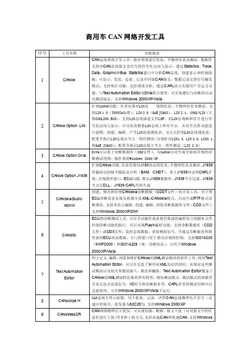
商用车CAN网络开发工具序号工具名称功能描述1 CANoe CAN总线系统开发工具,能对系统进行仿真,半物理仿真及测试。
数据库支持对CAN总线报文及信号的符号化访问与显示;通过Statistics, Trace, Data, Graphic和Bus Statistics窗口中分析CAN总线;创建显示和控制面板;可显示、发送、过滤、记录并回放CAN报文;数据记录支持信号触发模式;支持统计功能;支持离线分析;通过CAPL语言实现用户自定义功能。
与Test Automation Editor及DiV a联合使用,可实现通信与诊断的自动化测试验证。
支持Windows 2000/XP/Vista2 CANoe Option .LIN 扩展CANoe功能,从事实现对LIN总线的仿真,半物理仿真及测试。
支持LIN 1.3(TOYOTA标准),LIN 2.0(SAE J2602),LIN 2.1,COOL-LIN (又称COOLING BUS);支持LIN总线描述文件LDF,对LIN总线帧和信号进行符号化访问与显示;可以仿真整条LIN总线上所有节点,并对节点的功能进行建模;创建,编辑,产生LIN总线调度表;交互式控制LIN总线调度表;配置并执行LIN总线从节点一致性测试(分别针对LIN1.3, LIN 2.0, LIN2.1和SAE J2602);配置并执行LIN总线主节点一致性测试(LIN 2.0)3 CANoe Option DiV a DiVa可以基于诊断数据库(CDD文件),为CANoe自动生成全面而详细的诊断测试用例。
操作系统Windows 2000/XP4 CANoe Option J1939扩展CANoe功能,从而实现对J193协议的仿真,半物理仿真及测试。
J1939传输协议的细节跟踪及分析(BAM,CMDT),基于J1939协议的CAPL扩展,在线图形窗口,ECU扫描,默认J1939数据库,J1939节点过滤,J1939节点层DLL,J1939 CAPL代码生成5 CANdelaStudioAdmin创建,修改和管理CANdela诊断模板(CDDT文件)的开发工具,用于将ECU诊断需求实现为机器可读XML-CANdela格式。
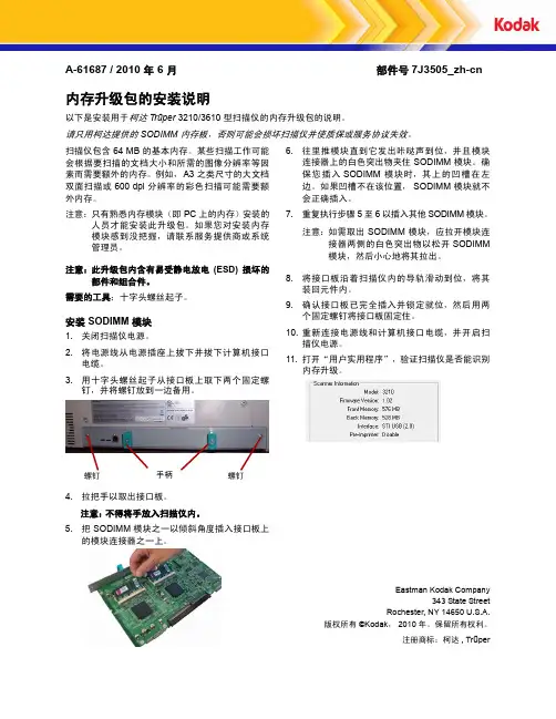
A-61687 / 2010 年 6 月部件号7J3505_zh-cn内存升级包的安装说明以下是安装用于柯达 Tr ūper 3210/3610 型扫描仪的内存升级包的说明。
请只用柯达提供的 SODIMM 内存板,否则可能会损坏扫描仪并使质保或服务协议失效。
扫描仪包含 64 MB 的基本内存。
某些扫描工作可能会根据要扫描的文档大小和所需的图像分辨率等因素而需要额外的内存。
例如,A3 之类尺寸的大文档双面扫描或 600 dpi 分辨率的彩色扫描可能需要额外内存。
注意:只有熟悉内存模块(即 PC 上的内存)安装的人员才能安装此升级包。
如果您对安装内存模块感到没把握,请联系服务提供商或系统管理员。
注意:此升级包内含有易受静电放电 (ESD) 损坏的部件和组合件。
需要的工具:十字头螺丝起子。
安装 SODIMM 模块1.关闭扫描仪电源。
2.将电源线从电源插座上拔下并拔下计算机接口电缆。
3.用十字头螺丝起子从接口板上取下两个固定螺钉,并将螺钉放到一边备用。
4.拉把手以取出接口板。
注意:不得将手放入扫描仪内。
5.把 SODIMM 模块之一以倾斜角度插入接口板上的模块连接器之一上。
6.往里推模块直到它发出咔哒声到位,并且模块连接器上的白色突出物夹住SODIMM 模块。
确保您插入SODIMM 模块时,其上的凹槽在左边。
如果凹槽不在该位置,SODIMM 模块就不会正确插入。
7.重复执行步骤 5 至 6 以插入其他 SODIMM 模块。
注意:如需取出 SODIMM 模块,应拉开模块连接器两侧的白色突出物以松开 SODIMM 模块,然后小心地将其拉出。
8.将接口板沿着扫描仪内的导轨滑动到位,将其装回元件内。
9.确认接口板已完全插入并锁定就位,然后用两个固定螺钉将接口板固定住。
10.重新连接电源线和计算机接口电缆,并开启扫描仪电源。
11.打开“用户实用程序”,验证扫描仪是否能识别内存升级。
Eastman Kodak Company343 State StreetRochester, NY 14650 U.S.A.版权所有©Kodak ,2010 年。
can-utils-master的canfdtest用法can-utils-master的canfdtest工具是用来测试和验证CAN FD (Controller Area Network Flexible Data Rate)功能的工具。
它可以用于发送和接收CAN FD 数据帧,并提供了一些选项来设置帧的参数和控制测试过程。
以下是canfdtest的一些常用用法示例:1. 发送CAN FD数据帧:`canfdtest can0 -i -t -f -D 1 -L 1 -n 1000`这个命令将会使用can0接口发送一千个CAN FD数据帧。
其中,-i选项表示使用随机数据填充帧的数据区域,-t选项表示发送数据帧而不是接收数据帧,-f选项表示发送CAN FD数据帧而不是普通CAN数据帧,-D选项表示数据区域的字节长度为1字节,-L选项表示数据区域的比特长度为1比特,-n 选项表示发送1000个数据帧。
2. 接收CAN FD数据帧:`canfdtest can0 -r`这个命令将会使用can0接口接收CAN FD数据帧。
3. 发送和接收CAN FD数据帧:`canfdtest can0 -i -r`这个命令将会使用can0接口发送和接收CAN FD数据帧。
4. 以指定周期发送CAN FD数据帧:`canfdtest can0 -i -f -c 1000`这个命令将会使用can0接口以1毫秒的周期无限循环地发送CAN FD数据帧。
以上只是一些简单的示例,canfdtest还有更多的选项可以用来设置不同的参数和操作。
你可以通过运行`canfdtest --help`命令来获取详细的帮助信息和用法说明。
GCAN Tools是一款功能强大的调试分析软件,主要用于车载网络通信的调试和分析。
以下是GCAN Tools的使用手册:1.安装与配置:首先,根据您的操作系统下载并安装GCAN Tools软件。
安装完成后,打开软件并根据需要配置车载网络通信的接口和参数。
确保正确连接车载网络通信设备,以便进行后续的调试和分析。
2.调试功能:GCAN Tools提供了丰富的调试功能,如实时监控、数据记录、断点控制等。
您可以使用这些功能来跟踪和分析车载网络中的数据包和通信状态。
通过实时监控,您可以观察到网络中的实时数据流,了解车辆的运行状态和各项参数。
3.分析功能:除了调试功能外,GCAN Tools还提供了强大的分析功能,帮助您深入了解车载网络通信的性能和问题。
您可以使用GCAN Tools的分析工具来分析数据记录文件,对车载网络通信进行全面的分析,包括数据包统计、协议分析、信号质量评估等。
4.故障排除:当车载网络通信出现问题时,GCAN Tools可以帮助您快速定位并解决问题。
通过实时监控和分析功能,您可以发现异常数据包或通信状态,从而判断故障的原因。
您可以使用GCAN Tools的故障排除工具来修复或解决相关问题,确保车载网络通信的正常运行。
5.更新与支持:GCAN Tools会不断推出新版本和更新,以增强软件的功能和修复潜在问题。
为了获得更好的使用体验和持续的技术支持,建议您定期检查并更新GCAN Tools软件。
总之,GCAN Tools是一款专门针对车载网络通信的调试和分析软件。
通过掌握以上使用手册中的基本操作和功能,您将能够充分利用GCAN Tools的强大功能,提高车载网络通信的调试效率和分析准确性。
基于周立功PCI-9820I 板卡的组态王CAN 通讯协议V2.2 2011-03-151.协议编制目的本协议是基于PCI-9820I 通讯卡而编写的CAN 通讯协议。
2.报文类型:2.1 服务数据报文SDO (Service Data Object )SDO 报文通过索引和子索引来传输数据,可批量下载和上传数据。
SDO 报文发送方式采用一对一或主从应答方式来传输数据。
2.2 过程数据报文PDO (Process Data Object )PDO 报文用来传输实时数据,数据从一个创建者传到一个或多个接收者。
PDO 报文发送方式包括定时触发、事件触发和请求应答触发。
3.CAN 帧格式3.1 帧结构一个CAN 帧包含13个字节,内容如下:◆ 帧信息:长度1字节,用于标识该CAN 帧的一些信息,如类型、长度等。
FF :标准帧和扩展帧的标识,1为扩展帧,0为标准帧。
本驱动固定为扩展帧。
RTR :远程帧和数据帧的标识,1为远程帧(用于请求数据),0为数据帧(用于数据传输)。
保留:值为0,不可写入1。
D3~D0:标识该CAN 帧的数据长度。
◆ 帧ID :长度4字节,标准帧有效位是11位,扩展帧有效位是29位。
内容如下:节点号(低字节) 类型 索引 备用(高字节)注意:1.本协议采用扩展帧格式。
2.本协议中帧ID采用高端对齐的方式,如果驱动程序接收的帧ID是低端对齐的话,需将帧ID左移三位后,再进行处理。
例如:计算机收到的扩展帧的帧ID(低端对齐)为0x2468ACE;实际处理时需将此帧ID左移三位(高端对齐)变成0x12345670。
即表示节点号为12H,类型为34H,索引为56H,备用为70H。
1-127(1-7f)|3.2 帧ID描述3.2.1 节点号节点号指下位机站点号,范围1-127。
3.2.2 帧类型帧类型描述了CAN帧的类别,定义如下:◆开关量PDO帧:用来传输开关量数据,一个开关量PDO帧可以传输最多64个数字I/O值。
cantools用法
cantools是一个开源工具,用于与CAN(Controller Area Network)总线进行通
信和解析。
CAN总线是一种在汽车和其他工业应用中广泛使用的通信协议,它允
许各种电子设备相互通信。
cantools提供了一套API和命令行工具,方便开发人员解析和处理CAN总线上的数据。
使用cantools,开发人员可以轻松地读取和写入CAN消息,实现汽车网
络中各个设备间的通信。
cantools的使用非常灵活。
用户可以使用cantools库直接从CAN数据文件中加
载数据库定义,也可以使用cantools命令行工具转换数据库定义文件格式。
数据库
定义文件包含了关于CAN总线上消息、信号和节点的信息,开发人员可以根据需
要解析其中的数据。
使用cantools,开发人员可以将CAN数据文件转换为各种数据格式,如JSON、XML等,以便后续处理或分析。
此外,cantools还提供了用于解析CAN消息的函
数和类,开发人员可以根据自己的需求自定义解析逻辑。
cantools的优点不仅仅在于可以解析CAN消息,它还提供了一系列的辅助函数
和工具,帮助开发人员处理和分析CAN数据。
开发人员可以使用cantools库进行
数据转换、过滤和验证,以确保数据的准确性和完整性。
总之,cantools是一个强大的工具,可以帮助开发人员处理和解析CAN总线上
的数据。
无论是开发汽车电子系统还是进行CAN数据分析,cantools都是不可或
缺的工具之一。
Card Motor Controller Controller Setting Software for LATCA(For Windows®7)LATC-Configurator[Before using this product]Read the "End-User License Agreement" shown on the next page carefully and accept the terms before using this software.End-User License AgreementSMC Corporation (hereinafter referred to as "SMC") grants the user (regardless the user is a corporation or an individual) a license to use this software "Controller Setting Software LATC-Configurator" (hereinafter referred to as "Software") provided according to this End-User License agreement (hereinafter referred to as "Agreement") under the articles listed below.The user is considered to have agreed to the terms of this Agreement by installing, copying or using this Software. Do not install, copy or use this Software if the terms of this Agreement cannot be accepted.The terms of this Agreement must be accepted by the user before downloading this Software if this Software has been supplied by SMC via the Internet or any other means. Do not download this Software if you cannot accept the terms of this Agreement.Article 1 (Grant of license)1. This Software is to be used in accordance with this Agreement non-exclusively for the limitedpurpose of using or setting SMC electrical actuators.2. This software can be installed and saved on a PC for the sole purpose specified in thepreceding paragraph.Article 2 (Restrictions)1. This software is not to be copied, except as specified in Articles 1-2.2. This software license is not to be transferred or lent wholly or in part to a third party, eitherfree of charge or for payment.3. Modification, translation, adaptation or reverse engineering of this software is not permitted. Article 3 (Other notices)1. Read the "Safety Instructions", "Precautions", "Specific Product Precautions" and"Specifications" described in the manual for the equipment when using any equipment controlled by this Software.2. This Software and the equipment controlled by it are subject to change without prior notice. Article 4 (Exemption of liability)SMC cannot take any responsibility for any damage incurred by the use of this Software. Article 5 (Termination)1. SMC has the full authority to terminate this agreement in the event of any terms andconditions have been breached.2. This Software and any copies thereof must be destroyed when this Agreement isterminated.Article 6 (Rights of this Software)The copyright and any other rights of this Software are owned by SMC, and protected by Japanese copyright laws and international treaty provisions.Article 7 (Governing law and jurisdiction)1. This Agreement shall be governed by Japanese laws.2. Any dispute arising from this Agreement shall be submitted in the first instance to theexclusive jurisdiction of the Tokyo District Court or the Tokyo Summary Court primarily.3. This Agreement has been made in the Japanese language as well. The Japanese text shallprevail over any inconsistencies between the Japanese and any translations thereof.1. ForewordPrepare the following before using this software (LATC-Configurator).1.1. Applicable computer-This software can be used on a computer with a Windows® 7 32bit or 64bit operating system.(Administrator rights are required to install the software and the drivers for the communication cable and virtual COM port.)-The computer screen resolution should be 1024 x 768 DPI or more.1.2. Preparation of communication cable and USB cablePrepare the communication cable (LEC-W2-C) and USB cable (LEC-W2-U) for connecting the Card Motor Controller to the PC.2. Installation procedures2.1. Installation of the USB drivers for the communication cablei. Insert the LATC-Configurator CD-ROM into the CD-ROM drive of your computer.Alternatively, after downloading the USB driver from our website, create a folder on the PC to unzip the USB driver.ii. Connect the communication cable LEC-W2-C to the USB port of the PC using the USB cable (LEC-W2-U). The message shown below will appear, as the driver has not yet been installed.iii. Open the Windows “Start” menu, right-click on “Computer”, select“Properties” and thereafter “Device Manager”.(Alternatively, open the Windows “Start” menu, select “Control Panel” and “System and Security” and click “Device Manager” in the “System” section.)iv. Double-click “Other Devices”, select the “SMC Serial Converter” with the“!”symbol and right-click to open the menu shown below on the left. Select“Update Driver Software”.v. Select the “Browse my computer for driver software” option when the dialog box shown below on the right appears.vi. When the dialog box shown below on the left appears, click "Browse", select the CD-ROM drive or the folder unzipped after downloading and the "¥Drivers¥32bit"folder for Windows7(32bit) and "¥Drivers¥64bit" for Windows7(64bit). Click "Next". vii. The warning message shown below on the right will appear. Select “Install this driver software anyway” to proceed with the installation.¥Drivers¥32bitviii. The following dialog box will appear when the SMC Serial Converter driver installation has been completed. Click the “Close” button.ix. Next the "virtual COM port driver" for the communication cable needs to be installed for the software to function properly.The “USB Serial Port” device should now appear in the “Device Manager” as shown below. Right-click on it and select “Update Driver Software”.Continue the installation of the "virtual COM port driver" following the same procedure beginning from step v.x. The following dialog box will appear when the installation has been completed.Click the “Close” button.2.2. Installation of the softwareCopy the controller setting software “LATC_Configurator.exe” on the CD-ROM or downloaded from our website to your PC or desktop computer.Double-click the copied file to start the software.CautionRead chapter "3. Check of the Communication Port" before starting the software.3. Check of the Communication PortWhen starting the LATC-Configurator software it is required to set the communication port number (COM no.) that has been assigned to the communication cable.Check the communication port number using the Windows “Device Manager” as follows. i. Connect the communication cable LEC-W2-C to the USB port of the PC using theUSB cable (LEC-W2-U).ii. Open the Windows Start menu, right-click on “Computer”, select “Properties” and thereafter “Device Manager”.(Alternatively, open the Windows “Start” menu, select “Control Panel” and “System and Security” and click “Device Manager” in the “System” section.)iii. Check in the “Device Manager” that the two driv ers have been installed as shown below.Check the COM number for the RS485 communication from the “Ports (COM & LPT)” device “SMC Serial Port”. In this example it is shown as COM3.The communication port number is needed when starting this software.CautionCheck the communication port number after connecting the communication cable.The communication port number depends on the USB port the communication cable is currently connected to.4. Starting the softwareWhen the "LATC-Configurator.exe" icon is double-clicked, the dialog box shown below will appear. Set the COM port number as confirmed according to the instructions in chapter "3. Check of the Communication Port".*If "COM port Not Available" is displayed and/or the number of COM port to which a controller setting cable is connected is not displayed as shown above, the controller setting cable is not recognised. Confirm that the wiring and two drivers are properly installed (Refer to "3. Check of the Communication Port ").5. Communication with the controllerThe connected controller is automatically detected when starting this software. However, if the communication settings, such as COM port number, are incorrect, communication cannot be established. Confirm the following before starting the communication.-That power is supplied to the connected controller.-That the controller and the computer are connected to each other via the communication cable.*If the dialog box shown, the controllerhas not been detected.Check the communication port setting,wiring, power supply to the controller andany other matter that may affect thecommunication with the controller.6. Functions of each functionRefer to the controller operation manuals for details of the controller and software functions.CautionDo not connect or disconnect the controller setting cable whilst theLATC-Configurator application is running.Disconnecting the cable during communication may cause a software corruption.The latest Operation Manual can be downloaded from the SMC's website shown below. Refer to SMC website for version update information.https:///4-14-1, Sotokanda, Chiyoda-ku, Tokyo 101-0021 JAPANTel: + 81 3 5207 8249 Fax: +81 3 5298 5362URL: https://Note: Specifications are subject to change without prior notice and any obligation on the part of the manufacturer.Windows is the registered Trademark or the Trademark of Microsoft Corporation in the United States or other countries.© 2019 SMC Corporation All Rights Reserved。
CAN总线分析工具BUSMASTERDesign DocumentCopyright 2011 Robert Bosch Engineering and Business Solutions Limited2 | BUSMASTER | TOCContentsInterface Details (6)Design Scope (7)Design Methodology (13)Design Notations (14)Design Considerations (15)Design overview (25)Architecture Design (26)DIL_Interface (26)IDIL_CAN (27)DIL_ES581 (28)DIL_BOA (29)DIL_Stub_CAN (30)ConfigDialogDIL (31)Bus Statistics (32)Simulation Engine (34)Project Configuration (38)Logger (42)Message Window (46)Filter (48)Session Replay (48)Node Simulation (50)Frame Transmission (55)Signal Watch Window (55)Test Automation (57)Test Setup Editor Lib module (58)Test Suite Editor and Executor Lib (59)Test Setup Editor (60)Automation Server Interface (61)Interface Design (63)User Interface (63)Component Interface (63)Test Suite Editor and Executor Lib (63)Design Alternatives (65)Design Feasibility (66)Design Tools used (67)Additional Hardware and Software required (68)Test Strategy (69)References (70)BUSMASTER | License Information | 3License InformationThis is a free document: you can redistribute it and/or modify it under the terms of the GNU Lesser GeneralPublic License as published by the Free Software Foundation, either version 3 of the License, or (at your option)any later version.This document is distributed in the hope that it will be useful, but WITHOUT ANY WARRANTY; without eventhe implied warranty of MERCHANTABILITY or FITNESS FOR A PARTICULAR PURPOSE. See the GNULesser General Public License for more details.You should have received a copy of the GNU Lesser General Public License along with this artifact. If not, see.4 | BUSMASTER | AcknowledgementAcknowledgementThe BUSMASTER application suite evoluted from its incipient stage of monolithic single bus - single controllerarchitecture towards the present stage of modular & reusable component based architecture, easily and seamlessly extendable to support multiple vehicle buses, exhibiting a rich set of carefully crafted feature list. Reaching ofsuch a milestone was possible only by the valuable contributions from many dedicated and skilful professionals who were involved at different cycles of the development process defin ing the trajectories of the product’sevolution, translating many innovative ideas into reality. The contributors so far are Mrs. Jalaja K.V, Mr. AmiteshBharti, Mr. Amarnath Shastry, Mr. Ratnadip Choudhury, Mr. Pemmaiah B.D, Mr. Raja N, Mr. Rajesh Kumar R,Mr. Anish Kumar, Mr. Pradeep Kadoor, Mr. Arunkumar Karri and Mr. Venkatanarayana Makam.This design document is the summation of all the relevant design documents, notes and an analysis report,produced and refined throughout the development process, and hence is an integrated version prepared to roll out the OSS version of BUSMASTER.BUSMASTER | List of Abbreviations | 5List of AbbreviationsAbbreviations, non-standard terms and acronyms that are used in this document are to be listed here.API Application Programming InterfaceBOA Basic Open ArchitectureCAN Controller Area NetworkDIL Driver Interface LibraryFlexRay A vehicle communication system developed bythe FlexRay consortiumGUI Graphic User InterfaceHLD High Level DesignJ1939 A CAN based higher layer vehicle bus standardLIN Local Interconnect NetworkOOD Object Oriented DesignOSS Open Source SoftwareRBEI Robert Bosch Engineering and BusinessSolutions LimitedSEI Software Engineering InstituteUI User Interface6 | BUSMASTER | Interface DetailsInterface DetailsThis document describes at length the various design aspects of BUSMASTER tool family which aims atsimultaneous support of any vehicle bus standard.For obvious reason the design approach primarily harps onthe principle of large-scale reuse and consequentlyis broadly inspired by product line model to leverage on this said aspect. The approach conforms to the SEIdefinition of product line engineering which is “A set of systems sharing a common set of features that satisfy the specific needs of a particular market segment or mission and thus are developed from a common set of core assets in a prescribed way”. So outlining of the engineering activity may be presented by the following:BUSMASTER | Design Scope | 7Design ScopeThe modules mostly have a one-to-one mapping with the feature set the application suite. The feature list against the implementing modules is tabulated below:8 | BUSMASTER | Design ScopeBUSMASTER | Design Scope | 910 | BUSMASTER | Design ScopeBUSMASTER | Design Scope | 1112 | BUSMASTER | Design ScopeThis design document addresses all the required different design aspects namely:ponent diagram2.State machine diagram3.Sequence diagram4.Class diagram5.Deployment diagramSo for every module the applicable design will be discussed on.BUSMASTER | Design Methodology | 13Design MethodologyHybrid design methodology consisting of structured and object oriented has been used.14 | BUSMASTER | Design NotationsDesign NotationsFor design, UML 2.0 notation is usedFor class nomenclature, the RBEI/ECM coding guideline has been followed.BUSMASTER | Design Considerations | 15Design ConsiderationsHere some the design requirements which are to be followed while carrying out development activitiesare described concisely. The BUSMASTER application design & architecture specification, followingcontinuous associated improvement activities, evoluted from a vast monolithic architecture into a properlyharmonised ensemble of loosely coupled reusable and efficient modules & components. As a natural and obvious consequence, certain patterns and structural approaches for development, albeit implicit, resulted. This document aims at capturing those steps and implied procedures.The various aspects can be listed as:1.Adequate loose coupling between UI and data: This application is GUI based for normal usage. However,usage as automation server is also possible.Towards this, a problem arises which is related to the complexity in harmonization of GUI with theapplication data (backend data).The user modifies the application data through the GUI which is a coarse visual reflection of the data. Thehandler modifies the data as per the user’s choice and domain rules and then updates the GUI based on the handler or function data.It is often missed that GUI is only one of the ways to initiate application data modification activity.Explicitness of the other one remains unconsidered mostoften. Therefore, the design and the very structuring of the sub modules & function list naturally don’t support this aspect. The result is obvious – whenever sucha need arises (e.g., exploitation of the feature from some other module while keeping the GUI on, automatedtesting etc), bugs with synchronization of GUI with the application data, unexpected crashes, duplication ofcodes etc creep in. This results in patch work, which further pervades into chaotic coding and many otherundesirable consequences.A sample code is presented below. The use case deals with 5 controls and takes the services of 5 utility APIcalls from the application data manager library.So long as we use the GUI to run this particular use case, things will proceed as expected, in the rightmanner. However, when it is done through some other means instead, (e.g., from a tester module running the application in the server mode, running the use case from another sub module etc). Something unexpectedhappens most often. In case of the former, a crash in case the GUI code doesn’t always validate the propernessof the window or control handles or object pointers. In case of the later, either duplicate code and hencepossibility of the GUI not appropriately reflecting the application data state. Add with it the numerous GUI conditions.16 | BUSMASTER | Design ConsiderationsVery defensive coding may solve the problem. Nevertheless – it should always be kept in mind that that ishard to practice and also this can make the code rather uglyand unreadable. Hence, a design solution may bethe most natural and therefore, best approach.// Data_Manager.cppRET_TYPE Function1_Exported(ARG_TYPE);RET_TYPE Function2_Exported(ARG_TYPE);RET_TYPE Function3_Exported(ARG_TYPE);RET_TYPE Function4_Exported(ARG_TYPE);RET_TYPE Function5_Exported(ARG_TYPE);// GUIClass.cpp#include "Data_Manager_extern.h"// Set of functions that operate on Control 1 upto 3void GUIClass::Modify_Control1(ARG_TYPE){// Modify control1 according to ARG_TYPE}void GUIClass::Modify_Control2(ARG_TYPE){// Modify control1 according to ARG_TYPE}void GUIClass::Modify_Control3(ARG_TYPE){// Modify control1 according to ARG_TYPE}void GUIClass::Handler(ARG_TYPE) // The handler implements the logic torealize{ // the desired functionality.if (Function1_Exported(..) == SUCCESS){Modify_Control3(..);if (Function5_Exported(..) == SUCCESS){if ( Function3_Exported(..) && Function2_Exported(..) ){// Code to update control 4Modify_Control2(..);}if (Function4_Exported(..) == FAILURE){Modify_Control1(..);}else{// Code to update control 5}}}}The solution crafted is layering of responsibilities by introducing a two-way communication with the data source. Any change in the back-end data can be indicated to the existing clients implemented either in eventnotification or call-back function. So the back-end data or the application data manager should have a well-defined interface. A typical use case can be realized by the execution of a few routines in some order, withadequate parameters.BUSMASTER | Design Considerations | 17The solution concept is inspired on the observer design pattern and the model-view-controller softwarearchitecture.2.Abstract data channel: Usage of BUSMASTER falls under two distinct categories namely, bus monitoring& analysis, and node simulation. Undercurrent of the first one is “retrieve data and represent the same in thedesired fashion”. All the major functionalities like frame display, logging, data interpretation, signal watchand graph, replay etc have frame data processing as the kernel of their activities. Tha t’s why it is of paramount importance to make the data retrieval procedure efficient and simple. The below diagram depicts such aschema ~18 | BUSMASTER | Design ConsiderationsThis calls for an optimised design for the message buffer classes which also qualifies the necessaryperformance criteria. Since frame data processing lies as the core of the activities, this issue is of paramountimportance and even an iota of improvement in this direction can significantly contribute is performanceelevation. The next point details on this.3.Optimised data design: Reiterating the RS, this discussion continues with the disclaimer that no loss of framedata can’t be guaranteed. Only the possibility of data loss can be brought down with efficient design of thedata structure. In a non-real time system like Windows this can be achieved by using buffer(s) as temporaryplaceholder(s) of data as shown in the figure above. The controller in addition contains a buffer that provides the first level of buffering whereas the application buffer is the last one. Hence we have an ensemble of twobuffers –one from the controller and the other from the application.BUSMASTER | Design Considerations | 19Hence the deciding factors can be the following:1.Size of the controller buffer2.Controller buffer management3.Size of the application buffer4.Application buffer management5.Retrieval process of frame data from the driver.‘A’ and ‘B’ are out of the purview of our discussion on analysis and strategy.Optimum size calculation of the application buffer depends on the following factors ~1. A.Current bit rate / throughput per second. It is finally the amount of data per second / millisecond thatmatters and hence the upper limit of total data at any moment.2. B.Space management of each frame entry. Since thepayload / data segment length of frames of buses like FlexRay or J1939 varies within a known range, a buffer of maximum allocable size can cater to a frame ofany allowable length. In another approach, only the space of the actual size may be used – given we knowthe current bit rate. The former approach may be called method of fixed-size entry whereas the later onemay be termed as method of variable-size entry.Formulation for method of variable-size entryLet rt bps be the data rate at any moment t. If T seconds is the total time for which the bus data are to beretained, then the total amount of space can be expressed as -S = # rt , where 1 <= t <= T.Assuming R be the average data rate,S = R * TLet C be the controller buffer size and M be the application buffer size. Hence, the following inequality musthold good -R * T < C + MConsidering the bus to be FlexRay, for each channel,Rmax = 10 MbpsRmax = 10 * 2^17 bpsCounting both the channels, the total data rate is 10 * 218 BpsCalculation of the optimized value of application buffer size depends on the realistic value of R and correctvalue of C.Assuming maximum data rate and neglecting C, we find for FlexRay ~M > 2.5 * T MBThe payload segment of a frame varies from 0 up to 127 WORDs. Hence the above formula is useful whenthe buffer for a frame is not assumed to be of fixed size and hence follows the implementation.Similarly, for a CAN controller with a single channel -Rmax = 1 MbpsRmax = 2^17 BpsAgain assuming maximum data rate and neglecting C, we find for CAN ~M > 1^27 * T kBFormulation for method of fixed-size entryThe first use case cited is for FlexRay bus.If Fcurr is the size in bytes of the current frame, thenFcurr = 8 + 2 * W, where 0 <= W <= 127 and W is the number of WORDs in the payload segment.。
CAN card Tools
URL /motion/cantools/cancard/ contains the link to the card drivers, firmware, and CANview software.
Installing PCI CAN card
Step 1 Load CAN Card Drivers
The files CANcard.inf and copleycan.sys can be placed in a temporary
file such as the desktop for locating with the Windows New Hardware
Found Wizard.
Step 2 Install the CAN Card
Shutdown windows and turn the power off and Install the CAN Card.
Image of PCI CAN card installed in PC slot. Card default has jumper installed for 121 Ohms termination.
Image of CAN1 (channel 0) connected with CAN Kit DB-9 to RJ45 adapter. Note: Last node on CAN network must also have 121 Ohms termination installed.
Turn the power ON and New Hardware will be detected.
Windows will run Found New Hardware Wizard.
Hit Next.
Select Search.
Select Specify a location.
Browse for the Drivers that you have placed on your PC.
If you put them on the desktop then look in the desktop folder.
Select CANcard.inf
Hit Next.
Hit Finish.
Windows Device Manager
The Windows Device Manager can be used to view the CANcard on your PC.
CME2 over Copley CAN Card
CME2 V4.2 or greater, available on the web, can recognize the Copley CAN card if the CAN card drivers are installed.
Step 1 Connecting Drives
Connect the CAN cable from the CAN Card to the first drive and then to any additional drives on the CAN network. Make sure the CAN card and last drive have termination installed. Set the drive node ID with switch (Xenus, AccelNet Panel, StepNet Panel, and Micro Development Kit.) or with jumpers on the signal connector. (AccelNet Micro Panel ACJ J5 +5V to IN6 bit 0 to IN9 bit 4, Xenus Micro Panel XSJ tbd)
Step 2 Connect CME2
Use CME2 tools\Communication Wizard to select CAN communication.
Select Copley, Channel 0 (if cable connected to bottom CAN 1 port), and 1Mbit/s default.
CME2 will scan all 127 possible nodes and identify any found nodes.
CME2 will upload drive parameters and display CAN tree, CAN Network node address, and CANopen State. The CAN Configuration screen can then be used to change settings if required. See CME2 Software manual for more details.
CML and CMO with Copley CAN Card
CML 1.07.20 or greater and CMO 2.1 or greater, available on the web, can recognize the Copley CAN card if the CAN card drivers are installed. See CMO Programmers manual and CANopen Programmers manual for more details.
CAN View
The CANview is now used to download firmware to the CAN Card. The Copley CAN monitor is able to view CAN messages and perform diagnostics on the CANopen network.
View Messages
Monitor bus
The CANview will show us the bus loading. The CAN bus can run well above 90% with no lost messages. If cables are greater than 20 meters at 1 mega bit or if stub lengths are greater than several inches, or if terminating resistors are not properly installed, we may see frame errors. (Tx, Rx, or open handles)
Network Analysis
The CANview will show us the approximate time for sending message to the furthest node and back. The results will be analyzed for good margin, low margin, or possible problem.
CAN Card Firmware
New firmware can be downloaded to the CAN card using the CANview program available on the web in the CANcardTools.zip file. New firmware will be required to take advantage of any new features.
To download firmware, select Tools\CANHardware to view the CAN Hardawre Configuration screen.
Press Update Firmware and select desired firmware.。