板式换热器使用说明书secret
- 格式:doc
- 大小:30.50 KB
- 文档页数:5
目录一、板式换热器概述 (1)二、板式换热器结构 (1)三、板式换热器型号表示方法 (2)四、板式换热器技术特点 (2)五、板式换热器的流程组合形式 (2)六、板式换热器的安装要求 (3)七、板式换热器的操作 (4)八、板式换热器的维修保养 (5)一、板式换热器概述板式换热器按GB16409-1996《板式换热器》进行设计、制造和检验。
板式换热器是以金属波纹板为传热元件的新型高效换热器。
由于板片组装后形成特殊流体通道,在较低雷诺数下可以产生湍流,并且不易结垢,板片材料选用优质进口不锈钢板、钛板等材质板材,传热系数高,相邻板片波纹波峰相互支撑,形成网状触点,提高了板片的刚性,可以承受较大的压差,保证了使用的安全可靠。
板式换热器所用板片是综合国内外先进技术而设计的高效换热板片,具有优越的传热性能、流通性能和耐压性能,流体分布均匀,不易结垢,以较小的压降取得最大的传热效果。
板式换热器应用“热混合”设计原理,使板式换热器的换热量、流量和允许压力降完全匹配,从而实现板式换热器的性能和面积最佳化。
板片的密封垫片结构独特,设计合理,性能稳定可靠,耐压能力强,维护便捷。
应用计算机设计选型,使板式换热器能够高效运行。
板式换热器的工作压力一般为 1.0MPa、1.6MPa,最高可以达到 2.5MPa.工作温度一般低于160℃。
板片材质一般为不锈钢(SUS304、SUS304L、SUS316、SUS316L)、钛板、钛钯合金、SMO254、哈氏合金等,密封胶垫使用丁腈橡胶、三元乙丙橡胶、氟橡胶、硅橡胶、食品橡胶等,板片和密封胶垫也可根据用户具体工况要求选用其它材料制造。
二、板式换热器结构板式换热器是由一组波纹金属板组成,板上有四个角孔,供传热的两种介质通过。
金属板片安装在一个侧面有固定压紧板和活动压紧板的框架内,并用夹紧螺栓压紧。
板片上装有密封垫片,将流体通道密封,并且引导流体交替地流至各自的通道内,形成热交换。
流体的流量、物理性质、压力降和温度差决定了板片的数量和尺寸。
管板式换热器设计说明书管板式换热器设计说明书一、概述管板式换热器是一种高效的换热设备,广泛应用于化工、石油、制药、食品等多个领域。
本设计说明书旨在介绍管板式换热器的设计原理、结构特点、选型方法、安装注意事项等相关内容。
二、设计原理管板式换热器采用管道和板式换热器结合的方式进行换热。
其主要原理是利用热流体在管道中流动时,通过管壁和板片与低温流体进行换热。
同时,管道和板片的结构也能使热流体均匀地流过,从而增强换热效果。
三、结构特点1.结构紧凑:管板式换热器体积小,结构紧凑,占用空间少,适用于场地狭小的场合。
2.换热效率高:管板式换热器采用多层板片进行换热,有效增加了换热面积,提高了换热效率。
3.应用广泛:管板式换热器适用于多种流体之间的换热,如液-液、气-液等。
4.可靠性高:管板式换热器采用优质材料制造,工艺先进,具有耐腐蚀、耐压等特点,具有较高的可靠性。
四、选型方法1.按照工艺要求确定换热参数:如换热量、流量、温度等。
2.确定流体性质:如流体介质、流速、粘度等。
3.进行换热器设计:选择合适的板片组合,计算换热器换热面积,确定尺寸和数量。
4.选择合适的材料:选择耐腐蚀、耐高温的合金材料,同时考虑生产成本。
五、安装注意事项1.在安装前,应仔细检查产品是否完好,检查连接处是否严密,以确保安装质量。
2.安装时应注意管路连接方式的选择,可选用法兰连接或焊接连接。
3.在碰到易燃易爆介质时,应注意防火防爆措施。
4.安装后应进行效验,检查管道连接是否泄漏,实验前应做好相应的准备工作。
六、总结管板式换热器具有结构紧凑、换热效率高、应用广泛、可靠性高等特点,是目前工业中使用的一种高效节能的换热设备。
在选型和安装过程中,应注意流体性质、工艺要求的确定,材料的选择和安装质量的保证。

设备安装运行维护使用说明书板式热交换器山东华昱压力容器有限公司目录一、板式热交换器概述 (1)二、板式热交换器结构 (1)三、板式热交换器型号表示方法 (2)四、板式热交换器技术特点 (2)五、板式热交换器的流程组合形式 (2)六、板式热交换器的安装要求 (3)七、板式热交换器的操作 (4)八、板式热交换器的维修保养 (5)一、板式热交换器概述板式热交换器按NB/T47004-2009《板式热交换器》进行设计、制造和检验。
板式热交换器是以金属波纹板为传热元件的新型高效换热器。
由于板片组装后形成特殊流体通道,在较低雷诺数下可以产生湍流,并且不易结垢,板片材料选用优质进口不锈钢板、钛板等材质板材,传热系数高,相邻板片波纹波峰相互支撑,形成网状触点,提高了板片的刚性,可以承受较大的压差,保证了使用的安全可靠。
板式热交换器所用板片是综合国内外先进技术而设计的高效换热板片,具有优越的传热性能、流通性能和耐压性能,流体分布均匀,不易结垢,以较小的压降取得最大的传热效果。
板式热交换器应用“热混合”设计原理,使板式换热器的换热量、流量和允许压力降完全匹配,从而实现板式换热器的性能和面积最佳化。
板片的密封垫片结构独特,设计合理,性能稳定可靠,耐压能力强,维护便捷。
应用计算机设计选型,使板式换热器能够高效运行。
板式热交换器的工作压力一般为 1.0MPa、1.6MPa,最高可以达到2.5MPa.工作温度一般低于160℃。
板片材质一般为不锈钢、钛板、钛合金、SMO254、哈氏合金等,密封胶垫使用丁腈橡胶、三元乙丙橡胶、氟橡胶、硅橡胶、食品橡胶等,板片和密封胶垫也可根据用户具体工况要求选用其它材料制造。
二、板式热交换器结构板式热交换器是由一组波纹金属板组成,板上有四个角孔,供传热的两种介质通过。
金属板片安装在一个侧面有固定压紧板和活动压紧板的框架内,并用夹紧螺栓压紧。
板片上装有密封垫片,将流体通道密封,并且引导流体交替地流至各自的通道内,形成热交换。
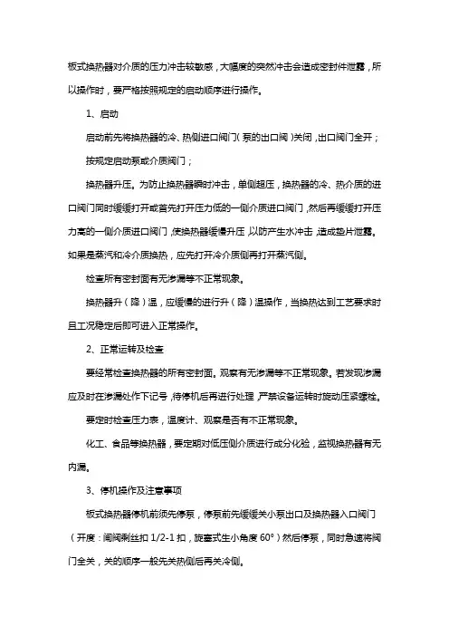
板式换热器对介质的压力冲击较敏感,大幅度的突然冲击会造成密封件泄露,所以操作时,要严格按照规定的启动顺序进行操作。
1、启动启动前先将换热器的冷、热侧进口阀门(泵的出口阀)关闭,出口阀门全开;按规定启动泵或介质阀门;换热器升压。
为防止换热器瞬时冲击,单侧超压,换热器的冷、热介质的进口阀门同时缓缓打开或首先打开压力低的一侧介质进口阀门,然后再缓缓打开压力高的一侧介质进口阀门,使换热器缓慢升压,以防产生水冲击,造成垫片泄露。
如果是蒸汽和冷介质换热,应先打开冷介质侧再打开蒸汽侧。
检查所有密封面有无渗漏等不正常现象。
换热器升(降)温,应缓慢的进行升(降)温操作,当换热达到工艺要求时且工况稳定后即可进入正常操作。
2、正常运转及检查要经常检查换热器的所有密封面。
观察有无渗漏等不正常现象。
若发现渗漏应及时在渗漏处作下记号,待停机后再进行处理,严禁设备运转时旋动压紧螺栓。
要定时检查压力表,温度计、观察是否有不正常现象。
化工、食品等换热器,要定期对低压侧介质进行成分化验,监视换热器有无内漏。
3、停机操作及注意事项板式换热器停机前须先停泵,停泵前先缓缓关小泵出口及换热器入口阀门(开度:闸阀剩丝扣1/2-1扣,旋塞式生小角度60°)然后停泵,同时急速将阀门全关,关的顺序一般先关热侧后再关冷侧。
如管线上装有放气阀,停机后打开放气阀放尽液体,避免设备管线被积存液体腐蚀或防止水冻结后将管线设备胀裂。
艾瑞德板式换热器(江阴)有限公司作为专业的可拆式板式换热器生产商和制造商,专注于可拆式板式换热器的研发与生产。
ARD艾瑞德专业生产可拆式板式换热器(PHE)、换热器密封垫(PHEGASKET)、换热器板片(PHEPLATE)并提供板式换热器维护服务(PHEMAINTENANCE)的专业换热器厂家。
ARD艾瑞德拥有卓越的设计和生产技术以及全面的换热器专业知识,一直以来ARD致力于为全球50多个国家和地区的石油、化工、工业、食品饮料、电力、冶金、造船业、暖通空调等行业的客户提供高品质的板式换热器,良好地运行于各行业,ARD已发展成为可拆式板式换热器领域卓越的厂家。
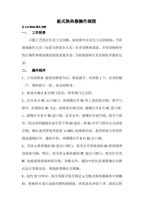
板式换热器操作规程以114-E02A到B为例一、工作职责日勤工艺组长负责下达切换、清洗指令以及完工后的验收;当班现场操作人员(包括当班保全人员)负责切换和清洗,并对切换程序的正确性和换热器的清洗质量负责;当班现场班长负责验收并做好记录。
二、操作程序1、工具的准备:接到切换指令后,准备扳手、对讲机1个、洁净的桶一个、塑料刷子一把、雨衣雨鞋等。
2、检查并确认B台阀门状况:所有阀门已关闭。
3、打开B台WC出口阀门;再缓慢打开WC管上部的放空阀、将空气排尽,直到排出WC为止,再将放空阀关闭;缓慢打开B台WC进口阀。
4、缓慢打开B台EG进口阀,直至全开;缓慢打开放空阀、将空气排尽,用洁净的桶接在放空管下将EG接住,将EG中空气排尽后关闭放空阀;确认备用管线顶部进114E01的球阀关闭,备用管线与常用管线连通阀打开。
通知中控,再缓慢打开B台EG出口阀;5、关闭A换热器的EG进出口阀门,依次打开其底部的EG排放阀和顶部放空阀;然后,再关闭A换热器的WC进出口阀门、依次打开其WC的底部排放阀和放空阀,切换完毕。
通知中控注意观察确认切换后运行效果良好,现场检查确认无泄漏。
6、过约20分钟后,保全用扳手拆开固定A台板式换热器换热片的螺栓,将换热片逐片逐面用塑料刷刷洗、再用清水冲洗干净。
清洗过程中还要注意防止换热片掉下伤人或割伤。
7、所有换热片清洗完后,由日勤工艺组长验收清洗质量,合格后按原样将换热器装好。
注意不要将换热片的方向装错;要检查换热器的夹紧厚度,保证符合供货厂家要求(详见供货商的操作手册)。
8、对A台板换进行填充试漏,打开A台WC管上部的放空阀,微开WC出口阀,待放空阀有WC流出时关闭放空阀。
打开A台EG管上部放空阀,微开EG进口阀,待放空阀有EG流出时关闭放空阀。
开始试漏(时间为24小时),合格后将A台WC出口阀全关及EG进口阀全关,进入备用状态。
9、清扫现场、将接得的EG进行回收。
按要求做好切换清洗记录。
高节能效率,低维护成本SpiralPro永远不会结垢SpiralCond:真空冷凝的理想解决方案SpiralPro用于液-液工况SpiralCond用于真空冷凝和蒸发SpiralPro用作蒸汽加热器SpiralCond“多合一”配置提升螺旋板式换热器的可持续性阿法拉伐全焊接螺旋板式换热器系列为高要求的液-液和两相工况提供了强大而可靠的选择,具有极低的维护要求。
全球已有超过80000台螺旋板式换热器装置交付使用,在化工、废水、采矿等应用领域久经验证,可应对其他类型的换热器难以解决的挑战,是值得信赖的可靠解决方案。
阿法拉伐螺旋板换的传热效率是同类管壳式换热器的2-3倍。
因此可回收更多的废热,从而为节约能源创造巨大潜力。
阿法拉伐螺旋板将更低的燃料成本和更少的排放相结合,可以为提升工艺流程的可持续性以及盈利能力提供更明智的解决方案。
同时,紧凑的设计能降低安装和材料成本,简化的服务减少了年度维护预算。
阿法拉伐螺旋板式换热器能缩短投资回收期、降低总投资成本。
对于涉及结垢流体、污泥、乳剂、泥浆、纤维或颗粒负载液体的工艺过程,阿法拉伐SpiralPro换热器的可靠性无与伦比。
SelfClean™的设计可防止脏流体结垢和堵塞,而这些脏流体会导致任何其他类型的换热器出现问题。
最大的正常运行时间和易于清洁性,极大地降低了运营费用,同时提高了生产能力。
SpiralPro换热器可以作为液液换热器或作为蒸汽加热器。
SpiralCond换热器是两相换热的高效解决方案,紧凑的立式安装,比同等效果的管壳式换热器占地面积小得多。
每一个SpiralCond换热器都完全根据所需的热负荷进行定制,并调整通道间距以提供最低的压降。
因此,Spiral-Cond换热器非常适合具有挑战性的真空冷凝和蒸发工况。
SpiralCond换热器能够安装在现有的工艺塔上或者作为“多合一”塔顶冷凝器,同时适配多种冷媒。
解决棘手问题的优势SpiralProSpiralCond适用于液液或者蒸汽加热工况适用于真空冷凝或蒸发工况能够被安装在现有的工艺塔上或者作为“多合一”塔顶冷凝器同时适配多种冷媒温度:-100°C 到400°C 温度:-100°C 到400°C 设计压力:全真空至 100 barg 设计压力:全真空至 100 barg 压差:高达50 barg 压差:高达50 barg 传热面积(最大):900 m 2传热面积(最大):2500 m 2 (“多合一“冷凝器)• 提升热回收效率可显著降低能源消耗,同时减少化石燃料消耗和二氧化碳排放。
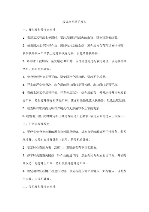
板式换热器的操作一、开车操作及注意事项1、在新工艺管线上使用时,要注意消除管线内的杂物,以免堵塞换热器。
2、如果用污水作冷却介质,或回收污水的余热,或介质内含有粒状固体物时,要在换热器入口端装上过滤器或除污器,以免堵塞换热器。
3、冷却水(被加热)温度超过40℃时,应尽可能先进行软化处理,以免换热器结垢,影响传热效果,4、检查管线连接是否正确,避免两种介质相混,引起不良后果。
5、开车前严格检查冷、热介质的进口阀门是否关闭,出口阀门是否开启。
6、完成上述工作后可开机。
开车先启动冷、热介质的泵,慢慢地打开冷介质的进口阀,然后打开热介质的进口阀,使介质缓慢地流入换热器,以免温度过高。
7、检查所有密封面及所有焊缝处有无渗漏等不正常的现象。
8、缓慢地升温,同时测定和计算是否满足工艺要求。
满足后即可进入正常操作。
二、正常运行及检查1、要经常检查换热器的所有密封面及焊缝,观察有无渗漏等不正常现象。
若发现渗漏,应及时在渗漏处作上记号,待停机后处理。
2、要定时检查压力表、温度计,观察是否有不正常现象。
3、停车时先慢慢关闭热、冷介质的进口阀,然后关闭两介质的出口阀。
开机时则反之,先打开出口阀,然后缓慢地打开进口阀。
4、要定期对低压侧介质进行化验,以免有高压侧介质混入。
如有混入,说明发生内漏,应停机处理。
三、停机操作及注意事项1、停机前必须先停泵,切断电源。
2、停泵后,先缓慢地关闭热介质进口阀门,再关闭冷介质的进口阀门。
最后关闭两介质的出口阀门。
3、如果管线上装有放空阀,应打开。
4、对温度较高的介质及腐蚀性介质,应尽量使设备放空,以免打开设备时烫伤人和腐蚀设备。
四、常见运行故障的诊断及处理(一)运行状况偏离工艺要求新投产的板式换热器如果达不到工艺要求,应仔细检查原始设计参数、设计计算、组装等是否正确,然后决定是否应增加或者减少换热面积,以及改变流程组合。
若板式换热器开始运行是正常的,经过一段时间运行后出现偏离工艺要求的情况,如出现出:压力降增大或减小;介质出口温度上升或下降。
固定管板式换热器手册固定管板式换热器是一种常见且重要的换热设备,广泛应用于工业生产过程中的热交换领域。
本手册旨在提供详细的使用和维护指南,以确保换热器的高效运行和长期可靠性。
1. 换热原理和工作过程:固定管板式换热器是一种传热效率高、紧凑型结构的装置。
它由一系列排列整齐的管道和板片组成,通过管道中的工作介质进行热量传递,实现冷热介质之间的热交换。
2. 设备安装和调试:在安装固定管板式换热器之前,必须仔细阅读生产商提供的安装说明,确保设备的正确摆放和固定。
安装过程中,需要特别注意与管道系统的连接、密封及电气接线等关键细节。
安装完成后,进行系统调试和泄漏检查,确保设备能够正常工作。
3. 换热器操作和维护:换热器操作前,需要检查并清理管道和板片,确保其清洁无阻。
运行过程中,要定期检查压力、温度和流量等参数,及时排除故障。
同时,定期对换热器进行维护,包括清洗、检修和更换磨损的部件等。
维护过程中,应遵循生产商提供的保养手册。
4. 故障排除和常见问题:固定管板式换热器可能会出现一些常见问题,如泄漏、堵塞、温度不稳定等。
对于这些问题,手册提供了一些排除方法和解决方案的指导,以帮助用户快速解决故障。
5. 安全注意事项:在使用固定管板式换热器时,必须遵循相关的安全操作规程。
手册列出了一些常见的安全注意事项,包括防止热介质泄漏、定期检查设备及周围环境的安全性,并提供了应急处理措施。
本手册作为固定管板式换热器的使用和维护指南,将帮助用户正确操作设备、确保其高效运行和延长使用寿命。
用户应认真阅读并按照手册的指导进行操作,同时定期进行维护和检修,以保障设备的安全稳定运行。
IntroductionThis manual provides information needed to install, operate and carry outmaintenance of the port filter used for gasketed plate heat exchanger with portsize 200 mm or larger.Intended useThe intended use of this equipment is to prevent foreign objects from enteringand causing clogging in gasketed plate heat exchangers.All other use is prohibited. Alfa Laval will not be held responsible for injury ordamage if the equipment is used for any other purpose than the intended usedescribed above.Environmental complianceAlfa Laval endeavours to perform its own operations as cleanly and efficientlyas possible, and to take environmental aspects into consideration whendeveloping, designing, manufacturing, servicing and marketing its products.Waste managementSeparate, recycle, or dispose of all material and components in a safe, andenvironmentally responsible way, or according to national legislation or localregulations. If there is any uncertainty regarding what material a component ismade of, contact the local Alfa Laval sales company. Use a certified (ISO14001 or similar) scrapping or waste handling company.UnpackingPacking material consists of wood, plastics, cardboard boxes and, in somecases, metal straps.•Wood and cardboard boxes can be reused, recycled or used for energyrecovery.•Plastics should be recycled or burnt at a licensed waste incineration plant.•Metal straps should be sent for material recycling.200001927-2-EN-GBThis document and its contents are subject to copyrights and other intellectual property rights owned by Alfa Laval Corporate AB. No part of this document may be copied, re-produced or transmitted in any form or by any means, or for any purpose, without Alfa Laval Corporate AB’s prior express written permission. Information and services provided in this document are made as a benefit and service to the user, and no representations or warranties are made about the accuracy or suitability of this information and these services for any purpose. All rights are reserved.© Alfa Laval Corporate ABMaintenance•All metal parts should be sent for material recycling.•Oil and all non-metal wear parts must be taken care of in accordance with local regulations.ScrappingAt end of use, the equipment shall be recycled according to relevant, local regulations. Besides the equipment itself, any hazardous residues from the process liquid must be considered and dealt with in a proper manner. When in doubt, or in the absence of local regulations, please contact the local Alfa Laval sales company.SafetySafety considerationsThe port filters shall be used and maintained in accordance with Alfa Laval’s instructions in this manual. Incorrect handling of the port filters may result in serious consequences with injuries to persons and/or property damage. Alfa Laval will not accept responsibility for any damage or injury resulting from not following the instructions in this manual.The port filters shall be used in accordance with the specified configuration of material, media types, temperatures and pressure for the specific plate heat exchanger were the port filter are used.Definitions of expressionsPersonal protective equipmentProtective shoesA shoe with a reinforced toe cap to minimize foot injuries caused by dropped articles.Protective helmetAny helmet designed to protect the head from accidental injury.Protective gogglesA pair of tight-fitting eyeglasses worn to protect the eyes from hazards.Protective glovesGloves that protects the hand from hazards.Working at heightIf the installation requires working at a height of two meters or higher, safety arrangements must be taken in consideration.DescriptionComponentsThe port filter consists of a cylindrical meshed tube with a flange in one end. The length of the filter tube is adapted for the total length of the plate pack including the thickness of the frame and pressure plate. The conical guide ring is inserted at the opposite port and keep the filter tube centered after installation. The welded rings in both ports provide a flat surface for flange gasket sealing against pipework and inspection cover.Following parts are required to install port filter.1.Port filter2.Conical guide ring3.Flange gasket (4 pieces per port filter)FunctionThe port filter is used to ensure high thermal efficiency of the plate heat exchanger by preventing foreign objects from entering and causing clogging of the plate pack. The port filter is designed to operate in conditions involving sea water, process water, cooling tower water or any kind of liquid containing particles with potential risk of disrupting the performance of the system.InstallationUnpackingFollow the instruction below to unpack the components of the port filter1Prepare an area with required space forunpacking.2Open the transport enclosure.3Check your shipment immediately uponarrival and make sure that the port filterreceived is in accordance with the orderspecification. In the event of damage, defectsor deficiency, immediately report the problemto the transport company and Alfa Laval.4Remove all additional components such asconical guide ring or other delivered partsfrom the transport enclosur.5Lift the port filter from the transport enclosure.Use lifting equipment with straps attachedaccording to picture or by hand for smallerport filters.Before installationPreparation of the plate heat exchanger before installation of the port filter. 1.Prepare the installation area around the plate heat exchanger and ensurethat required space is available.2.Installing port filter into an existing plate heat exchanger requirepreparation to ensure that correct port arrangement is in place for theinstallation. Consult Alfa Laval representative if any hesitation.3.Shut down, isolate and drain the plate heat exchanger by following theinstruction in section Shut-down4.Install port filter according to the section Installation of port filterShut-down1Slowly close the valve controlling the flowrate of the pump you are about to stop.2When the valve is closed, stop the pump.3Repeat the two steps for the other side for the second media.4If the plate heat exchanger is shut down forseveral days or longer, it should be drained.Draining should also be done if the process isshut down and the ambient temperature isbelow the freezing temperature of the media.Depending on the media processed, it is alsorecommended to rinse and dry the plate heatexchanger plates and connections.Installation of port filterInstallation of the port filter can be done when all preparation has been performed with shut-down and isolating the plates heat exchanger.1.Pressure plate 2.Frame plate 3.Inspection cover 4.Port filter 5.Conical guide ring 6.Flange gasket1Remove the connection flange pipe on the frame plate by loosening all nuts.2Attach one flange gasket at the port in the frame plate if not already in place.3Insert the conical guide ring into the port of the inlet flow (frame plate).4Attach one flange gasket to the outside of the conical guide ring flange.5Remove the inspection cover from the pressure plate by loosening all nuts. Uselifting equipment with straps attachedaccording to picture.6pressure plate if not already in place.7Insert the port filter into the port in the pressure plate.a)For large port filter use lifting equipment.b)Installation in lower port: Arrange strapsand chain pulley according to picture forinstallation in ports. Protect the threads ofthe tightening bolts by sliding a metal tubeover the tightening bolt.and chain pulley according to picture forinstallation in ports. Protect the threads ofthe tightening bolts by sliding a metal tubeover the tightening bolt.8Thread the port filter tube over the cone atthe opposite port by pushing the lower part of flange against the port and pull the upper part to guide the tube over the cone. Then pushthe port filter until the flange reach the liningof the port.9Attach the flange gasket to the outside of the port filter flange if not already in place.10Put the inspection cover back in place and fasten the nuts. Use lifting equipment withstraps arranged in the same way as in thestep of removing the inspection cover earlierin this instruction.11Attach the flange connection and fasten the nuts.OperationStart-upDuring the start-up, check that there are no visible leakages from the plate pack, valves or piping system.Centrifugal pumps must be started with valves closed and the valves must be operated as smoothly as possible.Do not run pumps temporarily empty on the suction side.1Check that the valve is closed between thepump and the unit controlling the system flowrate to avoid pressure surge.2If there is a vent valve installed at the exit,make sure it is fully open.3Increase the flow rate slowly.4Open the air vent and start the pump.5Open the valve slowly.6When all the air is expelled, close the airvent.7Repeat the procedure for the second media.MaintenanceTo keep a high performance of the plate heat exchanger the port filter needs to be cleaned at regular intervals. The frequency depends on volume of clogging or impurities in the media.Indicators of clogging filters can be pressure drop over the plate heat exchanger or difficulties to reach design temperature.Cleaning of port filters can be done by manual cleaning of port filter, see instruction Manual cleaning of the port filterManual cleaning of the port filter1Shut-down the plate heat exchangeraccording to the instruction Shut-down.2Close the valves and isolate the plate heat exchanger from the rest of the system.3Remove the inspection cover on the pressure plate by loosening all nuts. Use liftingequipment and arrange it according toinstruction in Installation of port filter.4Remove flange gasket5Grip around the port filter flange and pull out the port filter. If stuck, use a sharp tool toloosen it from the gasket. Use liftingequipment and arrange it according toinstruction in Installation of port filter.6Flush the port filter with water and brush to remove all clogging.7If clogging is present in the plate pack follow instruction in the Instruction Manual for theplate heat exchanger.8Re-insert the port filter, follow instruction in Installation of port filter.。
板式换热器操作手册
一、目的:建立纯化水制备岗位操作法,使操作工人正确操作该设备。
二、适用范围:适用于纯化水制备岗位。
三、责任者:纯化水制备岗位操作人。
四、板式换热器操作规程
1.原理:由于水温对RO膜的产水量影响较大,利用换热器来提高
进水温度,使RO
进水温保持在25℃,确保RO膜的产水量。
2.操作原理
正常运行时,通过换热器冷水侧出水管路上的温度检测,来控
制换热器热源进入阀门的开启与关闭。
目标温度设定值为
25℃,RO系统在运行状态,并且送水泵与高压泵已正常运行,检测水温低于25℃一定范围时,开启阀门,当水温高于25℃一
定范围时,关闭阀门。
五、注意事项
1)通过调整蒸汽管路上的手动阀来控制热水进入量,以保证冷水侧出水的温度在25℃;
2)RO运行时冷水侧出水的温度不得超过45℃,否则将损坏RO 膜;。
高效智能板式换热机组安装、运行、维护、使用说明书包钢重菱锅炉制造有限公司一、用途板式换热机组,是一套经过有机组合的完整的换热设备,它可进行汽-水、水-水的热交换,用户只需接上管道及电源即可使用。
本系列机组广泛用于住宅、机关、学校、厂矿、医院、宾馆等场合的采暖和空调系统。
二、结构特点1、板式换热机组采用蒸汽为热源时,在蒸汽进口前配置管壳式减温器,将蒸汽温度降到150℃以下,再进入板式换热器进行换热,使热介质温度低于胶垫能承受的温度,防止板式换热器密封垫的老化,使其寿命更长(高温胶垫可降到180℃以下)。
2、减温器和板式换热器的结合,充分利用板式换热器水—水换热系数高的特点,设备运行更加节能。
3、为保证设备正常运行,在板式换热器各进口阀门前安装过滤器。
4、变频定压补水系统,通过管网的远传压力表,调节补水泵的流量。
当系统水膨胀超压时,通过安全阀开启泄压达到系统稳压目的。
5、采用本公司生产的高性能板式换热器,机组体积小,占地面积少。
6、设备结构紧凑,便于安装和运输;设备布置便于检修,且流程顺畅阻力小。
7、操作简便,工况稳定,无噪音。
8、耐腐蚀、易拆卸,清垢维修简便。
三、选用说明1、该产品适用于住宅、机关、学校、厂矿、医院、宾馆等场合采暖和空调系统。
2、机组允许工况不能超过设备铭牌和板式换热器铭牌规定的参数。
3、热媒种类为蒸汽或高温水,我公司可根据您的具体工况和要求进行单独设设计和制造。
4、循环泵系统正常为一泵备用。
5、应留出相对独立的控制操作间,以安装控制柜。
6、换热机组出厂时不进行保温,为节能用户应自行保温。
7、用户如对机组的技术性能、配置、外形尺寸、接管方向等有具体的特殊要求时,我公司免费为用户和设计单位提供咨询和选型方案。
四、工作原理二次网路的回水经过除污器,流入二次网路循环泵;加压后进入板式换热器(汽水时还经过列管减温器)与一次网进行交换,达到二次网供水所需的水温后,进入二次网供水管路。
在循环水泵的进出口侧增加了泄压管,防止了因突然停泵造成水击事故。
螺旋板式换热器的使用说明传热元件由螺旋形板组成的换热器。
螺旋板式换热器是一种高效换热器设备,合用汽-汽、汽-液、液-液,对液传热。
它合用于化学、石油、溶剂、医药、食物、轻工、纺织、冶金、轧钢、焦化等行业。
按结构方法可分为不成拆式(Ⅰ型)螺旋板式及可拆式(Ⅱ型、Ⅲ型)螺旋板式换热器螺旋板式换热器结构及功用:1、本设备由两张卷制而成,组成了两个均匀的螺旋通道,两种传热介质可进行全逆流运动,大大增强了换热后果,即使两种小温差介质,也能抵达梦想的换热后果。
2、在壳体上的接纳采用切向结构,局部阻力小,由于螺旋通道的曲率是均匀的,液体在设备内运动没有大的转向,总的阻力小,因而可提高设计流速使之具有较高的传热才干。
3、I型不成拆式螺旋板式换热器螺旋通道的端面采用焊接密封,因而具有较高的密封性。
4、II型可拆式螺旋板换热器结构事理与不成拆式换热器基本一样,但个中一个通道可拆开清洗,非凡合用有粘性、有沉淀液体的热交流。
5、III型可拆式螺旋板换热器结构事理与不成拆式换热器基本一样,但其两个通道可拆开清洗,合用局限较广。
6、单台设备不能知足运用要求时,可以多台组合运用,但组应时必需契合下列规矩:并联组合、串联组合、设备和通道间距一样。
搀杂组合:一个通道并联,一个通道串联。
我公司是生产换热器的专业性单位,多年来,在各大专院校、科研单位的鼎力相助和各用户单位的大力支持下,已形成了一定规模的换热器生产体系。
我公司生产螺旋板式换热器、列管式冷凝器(换热器)、烟气换热器、空气冷却器等。
以及生产各种规格型号的换热器和散热器,而且还在不断地开发新的散热器品种。
目前我公司散热器的主要品种有:发酵设备、换热设备、搅拌设备、石油化工设备、高温水或蒸汽散热器(GL型、SRZ型、U型、SRL 型等)、高温导热油散热器(FUL型)、表面空气冷却器(KL型、TLS型)。
翅片管型式有:绕片式、挤压式、串片式、焊片式等。
翅片管材质有:钢、铜、铝、不锈钢、钢铝复合、铜铝复合等。
E 5.815.1.1 / 08.16are particularly2FunctionFluids flow in counterflow through the plate heat exchanger:With brazed plate heat exchangers it is possible to reverse the inlet and outlet connections of a medium without adversely affecting the function. However, to guarantee the counterflow principle, the inlet and outlet of the other medium must also be changed. However, changing the cold and hot side is not recommended. The plate heat exchangers are designed to have hot fluid always flowing through the outer plate. If cold medium flows through, condensation could form on the outside of the heat exchanger.With gasketed plate heat exchangers it is not possible to change the connections because of the more complex plate stamp pattern. In this case the connections can be selected before manufacture of the plate heat exchanger. Please consult our technical sales department.In counterflow, the hot medium is cooled more rapidly than in parallel flow because the cold medium flows in the opposite direction to the hot fluid.Multi-way flow pattern:The connections are on the front cover plate and the end cover plateOne-way flow pattern:All connections are on one sideE 5.815.1.1 / 08.16Sizing ProgramThe sizing program for brazed plate heat exchangers helps you to select the right size and number of plates.Please ask for the latest version from the technical sales department.For gasketed plate heat exchangers please fill in the Specification Sheet in this brochure and send it to the technical sales department. We will help you to find the appropriate plate heat exchanger for your specific application.Application FieldA plate heat exchanger can be used wherever there should be heat transfer between two media.Typical applications are: l Hydraulic systems l Pressesl Lubrication systems l Test rigsl Motors / enginesSectional ViewCooling CapacityThe maximum cooling capacity of a plate heat exchanger depends on several factors:l the inlet temperature of the hot and cold medium l the flow rate of the hot and cold medium lthe media used.Cross-section of abrazed plate heat exchanger4Specification Sheet for Plate Heat ExchangersIn order to be able to make the correct selection, it is necessary to have various data to hand. The following check-list is designed to help.Project:Contact:Telephone:E-mail:GeneralDesign pressurebarHot sideMedium to be cooled○ Oil ISO VG SAE○ Water○ Water glycol % Glycol:%○ Other medium(Please attach technical datasheet for medium, if available.)Inlet temperature:°C Flow rate:l/min orm³/hMax. pressure drop:bar Required cooling capacity:kWorOutlet temperature:°CCold sideCooling medium:○ Oil ISO VG SAE○ Water ○ Seawater (Gasketed PWT only)○ Water glycol % Glycol:%○ O ther medium(Please attach technical datasheet for medium, if available.)Inlet temperature:°C Flow rate:l/min orm³/h(if known)Max. pressure drop:barCommentsE 5.815.1.1 / 08.16GeneralWith plate heat exchangers, the heat from the fluid being cooled is transferred to a cooling fluid. The advantage is that they can maintain the fluid temperature at a very low and stable level –depending on the temperature of coolant.Brazed heat exchangers thereforeensure efficient heat transfer combined with compact dimensions and low Product FeaturesBrazed heat exchangers consist of a stack of stamped heat transfer plates with connections in stainless steel. The plates are vacuum brazed with copper or nickel.The plates have smoothed edges and the end plate is provided with edge protection.The special stamp pattern of the plates induces a turbulent flow which is necessary for optimum heat transfer and which in addition has a self-cleaning effect because the high level of wall friction reduces deposits on the surface.6Application FieldCooling circuits operated using water,coolant, HFC operating fluid or oil.Typical applications are:l Machine toolsl Pressesl Injection moulding machinesl Motors / enginesl Test rigsl GeneratorsWater QualityThe following limits refer to copper-brazed plate heat exchangers and a watertemperature of + 60°C:0: Corrosive+: SuitableFor nickel-brazed versions, please contact the technical sales department.Oil coolingHeat pumpChillerVacuum pumpOil tankAir coolerCompressorOil separatorEconomizerBypassAir inletPump30 °C30 °C30 °C25 °C25 °C25 °C TransmissionoilAir outletCoolantreceiverCoolantCoolingwaterCoolingwaterCon-denserCon-sumerExpansion valveCondenserCompressorWaterheaterWaterPumpCoolingwaterCoolingwaterCoolingwaterCom-pressorWater-cooledmotorE 5.815.1.1 / 08.163455621HYDAC HEX S400-10-00/G3/4"33 1.33383847HYDAC HEX S400-14-00/G3/4"42 1.53455623HYDAC HEX S400-20-00/G3/4"55 1.83399435HYDAC HEX S400-30-00/G3/4"78 2.33455655HYDAC HEX S400-40-00/G3/4"1012.8HYDAC HEX S400HYDAC HEX S6103366746HYDAC HEX S610-10-00/G1"34 2.53361012HYDAC HEX S610-20-00/G1"58 4.23366754HYDAC HEX S610-30-00/G1"82 5.53366759HYDAC HEX S610-40-00/G1"106 6.93366760HYDAC HEX S610-50-00/G1"1308.253366761HYDAC HEX S610-60-00/G1"1549.63366762HYDAC HEX S610-70-00/G1"17810.93527300HYDAC HEX S610-80-00/G1"20211.03366763HYDAC HEX S610-100-00/G1"25014.23366764HYDAC HEX S610-120-00/G1"29816.680±276±240L27SW32154190±2194±2Female thread G¾"l = 18 mm106±2102±250L27SW41250302±2306±2Female thread G1"l = 20 mmDimensionsE 5.815.1.1 / 08.1683366787HYDAC HEX S615-10-00/G1"34 5.33366788HYDAC HEX S615-20-00/G1"587.53366790HYDAC HEX S615-30-00/G1"829.73366792HYDAC HEX S615-40-00/G1"10611.93366793HYDAC HEX S615-50-00/G1"13014.13366794HYDAC HEX S615-60-00/G1"15416.33366815HYDAC HEX S615-80-00/G1"20220.73383853HYDAC HEX S615-100-00/G1"25025.7HYDAC HEX S615HYDAC HEX S7223457465HYDAC HEX S722-20-00/G1 1/2"6215.33457473HYDAC HEX S722-30-00/G1 1/2"8619.43457474HYDAC HEX S722-40-00/G1 1/2"11023.53457486HYDAC HEX S722-50-00/G1 1/2"13427.63457489HYDAC HEX S722-60-00/G1 1/2"15831.73457490HYDAC HEX S722-70-00/G1 1/2"18235.83457491HYDAC HEX S722-80-00/G1 1/2"20640.03457493HYDAC HEX S722-90-00/G1 1/2"23044.03457494HYDAC HEX S722-100-00/G1 1/2"25448.03457495HYDAC HEX S722-120-00/G1 1/2"30253.43457496HYDAC HEX S722-150-00/G1 1/2"37469.03673112HYDAC HEX S722-160-00/G1 1/2"39472.73463069HYDAC HEX S722-190-00/G1 1/2"47084.8186±2182±292L27SW66519609±2613±2Female thread G1½" l = 25 mm106±2102±250L 27SW41466518±2522±2Female thread G1"l = 20 mmE 5.815.1.1 / 08.16HYDAC HEX S522246±2241±2174L 27SW55456523±2528±2Female thread G1½"l = 25 mmHYDAC HEX Z800Special size for high cooling capacities and large volumes:l Diagonal flow patternl Connections: threaded bolts with female ormale threads, flange, soldered or SAE connections3383854HYDAC HEX S522-20-00/G1 1/2"6017.63383906HYDAC HEX S522-30-00/G1 1/2"8422.83383908HYDAC HEX S522-40-00/G1 1/2"10828.03383909HYDAC HEX S522-50-00/G1 1/2"13231.23383910HYDAC HEX S522-60-00/G1 1/2"15638.43383911HYDAC HEX S522-70-00/G1 1/2"18043.63383913HYDAC HEX S522-80-00/G1 1/2"20448.83383914HYDAC HEX S522-100-00/G1 1/2"25259.23651724HYDAC HEX S522-110-00/G1 1/2"27660.83383925HYDAC HEX S522-120-00/G1 1/2"30069.63383926HYDAC HEX S522-150-00/G1 1/2"37285.23738950HYDAC HEX S522-160-00/G1 1/2"39684.83383927HYDAC HEX S522-190-00/G1 1/2"468106.0321316220Ø3070a aa5050L180270650(650)751746E 5.815.1.1 / 08.1610Please note:For mounting heat exchangers with 60 plates and above, two clamps are recommended.HYDAC Part No.HYDAC Type Code c [mm] d [mm]l [mm] b [mm]3092917HYDAC HEX S400194802392193014028HYDAC HEX S6103061063513313014029HYDAC HEX S6155221065665463343306HYDAC HEX S5225282465735533013884HYDAC HEX S722613186658638Rubber profileRubber profileM8C ±2B (10)LOctagon nutClamping band Cylinder head screwGuide rollerMounting plateCooler not suppliedE 5.815.1.1 / 08.16GeneralWith plate heat exchangers, the heat from the fluid being cooled is transferred to a cooling fluid. The advantage is that they can maintain the fluid temperature at a very low and stable level –depending on the temperature of coolant.Gasketed plate heat exchangers are particularly suitable for large flows and high cooling capacities and are therefore a useful supplement to the brazed range.Product FeaturesGasketed plate heat exchangers consist of a stack of individually stamped heat transfer plates and gaskets. The plate stack is clamped using bolts in a frame consisting of a fixed cover and a moveable cover. The advantage is that the plate heat exchanger can also be dismantled for cleaning and maintenance. Furthermore it is possible to add more plates at a later date to achieve a higher capacity.There are several sizes with varying numbers of plates and different stamp designs available to cover the capacity range. In this way they can cater for heavily contaminated or high viscosity fluids, or even if the temperature difference between the hot and cold medium is only minimal.SymbolWater QualityA = under normal circumstances, good resistanceB = danger of corrosion, especially if several B substances are presentC = n ot suitable>300 ppm Ti Ti Ti Ti Application FieldCooling circuits in counterflow whichare operated using water, coolant,HFC operating fluids or oil. Forapplications using other fluids pleasecontact the specialist department.Typical applications are:l Hydraulic systemsl Pressesl Lubrication systemsl Test rigsl Motors / enginesNote: This table is not exhaustive and serves only as a guide.E 5.815.1.1 / 08.16DimensionsThe dimensions can vary according to the frame type. Gasketed plate heat exchangers are calculated individuallyaccording to the application. You will find the relevant frame length L on the data sheet for your calculation.Pressure ranges: 16 bar, 25 barSize Dimension H Dimension C H8621 mm 381 mm H16896 mm656 mm200200160L12L+ 100L +60L20Ø1830F 4F 1F 3F 27030H40200CInstallationFramePressure ranges: 16 bar, 25 barSize Dimension H Dimension CH14694 mm 394 mm H28994 mm 694 mm H401,194 mm894 mmH14 / H28 / H40300300LLHHH + 50C C160160F 4F 4F 1F 1F 3F 3F 2F 2126126300260L+ 100L + 60L20Ø18InstallationFrame 16 barFrame 25 barE 5.815.1.1 / 08.16395395LLHHCC132132F 4F 4F 1F 1F 3F 3F 2F 2192192344351Pressure ranges: 10 bar, 16 barSize Dimension H Dimension C H18626 mm 380 mm H38946 mm 700 mm H621,296 mm1,050 mmH18 / H38 / H6230275L +1021720Ø18Ø18Ø14HH + 70C205BL2035F 4F 1F 3F 2225B B - 100140LL +55Ø18Ø18Pressure ranges: 10 bar, 16 bar, 25 barSize Dimension H Dimension C Dimension B H42 / H441,238 mm 719 mm 495 mm H941,884 mm 1,365 mm 480 mm H1282,291 mm1,771 mm480 mmInstallationFrame 10 barFrame 25 barInstallationFrameE 5.815.1.1 / 08.16Pressure ranges: 10 bar, 16 barSize Dimension H Dimension C H741,441 mm 1,070 mm H1021,855 mm1,484 mmPressure ranges: 10 bar, 16 bar, 25 barSize Dimension H Dimension C Dimension B 10, 16 bar Dimension B25 bar H82 / H841,450 mm 890 mm 608 mm 640 mmH1241,852 mm 1,292 mm 608 mm 640 mm H1722,254 mm 1,694 mm 608 mm 640 mm H2202,654 mm2,094 mm608 mm640 mmH82 / H84 / H124 / H172 / H220H H + 300C275BL20F 4F 1F 3F 2296BB - 100L +50Ø18Ø18HH + 70C 200480L2035F 4F 1F 3F 2238480380140LL +55Ø18Ø18InstallationFrameInstallationFrameNoteThe information in this brochure relates to the operating conditionsand applications described.For applications and operating conditions not described, please contactthe relevant technical department. Subject to technical modifications.。
板式换热器操作规程《板式换热器操作规程》一、目的为了保证板式换热器的正常运行,提高换热效率,延长设备的使用寿命,特制定本规程。
二、操作前准备1. 检查板式换热器设备及周围环境,确保无杂物堵塞。
2. 查看换热器工作参数是否正常。
3. 检查冷却水、热介质等流体供给情况。
三、操作步骤1. 打开换热器进口和出口阀门。
2. 检查冷却水和热介质供给情况。
3. 根据现场情况调整流速和压力。
4. 监测换热器工作状态,发现异常及时处理。
四、操作注意事项1. 遵守设备操作规程,严格按照工艺要求进行操作。
2. 定期清洗换热器,保持清洁。
3. 注意换热器的进出口温度和压力变化,及时调整。
4. 确保冷却水和热介质的质量,避免产生结垢及腐蚀。
5. 检查换热器设备及管道连接是否紧固牢靠。
五、操作后处理1. 关闭换热器进出口阀门,停止流体供给。
2. 对设备和周围环境进行清洁。
3. 记录换热器的运行参数和异常情况。
六、安全注意事项1. 操作人员必须具备相关操作证书和经验,熟悉设备操作规程。
2. 在设备操作过程中,必须严格遵守安全操作规程,如穿戴好安全防护用品,严格执行相关操作规定。
3. 操作人员须具备紧急处理意外事故的知识和技能,熟悉设备的应急处理方法。
七、设备保养1. 定期进行设备的保养和检修,及时更换易损件。
2. 定期清洗设备,保证设备干净、卫生。
3. 注意设备的工作状态,发现异常及时处理,避免影响设备正常运行。
八、规定1. 操作人员必须按照本规程进行操作,严禁违反规程操作。
2. 对于发现设备异常情况,必须及时报告上级领导,并及时采取合理措施处理。
以上就是《板式换热器操作规程》,希望广大操作人员认真执行,确保设备的安全运行。
4、(1)简单流程表达式热1×7,流程组合如图6。
冷1×7(2)复杂流程表达式热1×3+1×3,流程组合如图7。
冷1×4+1×3(3)带中间隔板的流程表达式热1×2+1×11×3,流程组合如图8。
冷1×2+1×21×45、板片的装配顺序(1)在装配好的框架上,按制造厂提供的《板式换热器安装图册》中的流程组合图,由固定压紧板侧依次装配,A、B板交替排列。
(2)如果有中间隔板,在装配框架时,连同中间隔板一起装好,按流程组合图先装固定压紧板和中间隔板之间部分板片,依次排列就位。
五储存吊运安装1、储存要求(1)板式换热器在安装前储存若超过半年时,应预先松开夹紧螺柱,使板片压紧尺寸不小于1.1B,使用时再把合至压紧尺寸B,如图9。
(2)板式换热器应在干燥通风的库房内存放,环境温度不得超过40℃。
图92、吊运(1) 设备一般是整体装箱发运,箱体上标明正立,重心标记;起吊包装箱时应考虑重心位置。
(2)板式换热器在固、活压紧板上设有起吊装置,起吊时,吊绳不得挂套在接管、导杆或夹紧螺柱上。
3、安装(1)按随机文件《板式换热器安装图册》给定的设备安装尺寸,准备地基平台,并按图布置地脚螺栓位置,换热器四周应有足够的空间,以便安装和维护。
换热器与最近的隔离物(如墙)之间的距离至少应为1m。
(2)设备放置在地基平台上,先对准固定压紧板侧连接板上的螺孔,按下导杆进行找平,平面度不大于3/1000,然后紧固地脚螺栓。
(3)按介质标牌连接对应管线,所有与换热器连接的管线必须安装关断阀,靠近换热器的冷热介质的进口管线应安装过滤器,高处安装排汽阀,最低处应安装排水(污)阀,介质进出口管线均须安装温度计、压力表。
(4)当活动压紧板侧有进出口接管时,管线最好安装金属软管短节,以便在操作过程中,补偿由于压紧尺寸B的变化使活动压紧板位置发生变化。
可编辑
精品
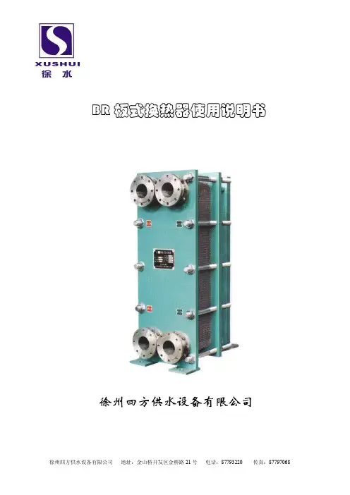
板式换热器使用说明书
一、概 况
板式换热器是液—液、液—汽进行热交换的理想设备。它具有换热效率高,热损失小、
结构紧凑轻巧、占地面积小、安装清洗方便、应用广泛、使用寿命长等特点。在相同压力损
失情况下,其传热系数比管式换热器高3—5倍,占地面积为管式换热器的三分之一,热回
收率可高达90%以上。板式换热器广泛应用于冶金、石油、化工、食品、制药、船舶、纺织、
造纸等行业,是加热、冷却、热回收、快速灭菌等用途的优良设备。
二、结构及外形尺寸
BR型系列产品,整机装配有普通式结构(不经常拆洗工况采用)和悬挂式结构(拆洗
较频繁的工况采用)两种。
普通式结构由人字形波纹板片、密封垫、压紧板、上下定位螺栓、压紧螺栓等主要零
件组成。
悬挂式结构由人字形波纹板片、密封垫、固定压紧板、中间板、活动压紧板、支架、
上下定位横梁、压紧螺栓等主要零件组成。
三、技术参数及规格型号表示方法
1、技术参数
型 号
项 目
BR0.05
BR0.1 BR0.2
单片换热面积㎡ 0.05 0.1 0.22
板片尺寸mm 500×168 660×250 970×330
板片厚度mm 0.8 0.8 0.8
角孔直径mm 38 60 75
接管直径mm 28 38 46
波纹形状 人字形波纹
波纹间距mm 10 12 12
平均板间距mm 3.8 4.2 4.2
可组合换热面积㎡ 0.5~5 4~10 10~38
最大允许使用压力Mpa 0.4~2
最高允许使用温度 ℃ 一般要求120~160,特殊要求可达250
可编辑
精品
传热系数 W/㎡℃ 2000~6000
2、规格型号表示方法:
表示:人字形板式换热器,单板片换热面积0.2㎡,经过第一次改型,工作压力1.6Mpa,
工作温度150℃,单机公称换热面积20㎡,流程组合形式 2×25 ,式中分子表示热介质,
分母表示冷介质,2表示程数有2程,亦为折流次数,25表示每程有25条流道。
四、流程工作原理
板式换热器由于板片波纹表面的特殊作用,使流体沿着狭窄弯曲的通道流动其速度的大小方
向不断的改变,致使流体在不大的流速下(Rc=200时),激起了强烈端动,因而加快了流
体边界层的破坏,强化了传热过程,有效地提高了传热能力。 并使其具有结构紧凑、金属
耗量低、操作灵活性大、热损失小、安装、检查拆洗方便、耐腐性强、使用寿命长等突出优
点。
换热器的流程是由许多板片按一定工艺及需方技术工作要求组装而成的。 组装时A板和B
板交替排列,板片间形成网状通道四个角孔形成分配管和汇合管,密封垫把冷热介质密封在
换热器里,同时又合理的将冷热介质分开而不致混合。在通道里面冷热流体间隔流动,可以
逆流也可以顺流,在流动过程中冷热流体通过板壁进行热交换。板式换热器的流程组合形式
很多,都是采用不同的换向板片和不同组装来实现的,流程组合形式可分为单流程,多流程
和汽液交换流程,混合流程形式。
要根据工艺条件来选择换热器的流程组合。(图二)
五、换热器安装
1、板式换热器的两块压紧板上有4个吊耳,供起吊时用,吊绳不得挂在接管、定位横梁或
板片上。
2、换热器周围要留有1米左右的空间,以便于检修。
3、冷热介质进出口接管之安装,应严格按照出厂铭牌所规定方向连接,否则,换热器性能
将受到影响。
4、安装管路时,应在管路上配齐阀门、压力表、温度计,流量控制阀应装在换热器进口处,
在出口处应装排气阀。
5、设备管道里面要清理干净,防止砂石焊渣等杂物进入换热器,造成堵塞。
6、当使用介质不干净,有较大颗粒或长纤维时,进口处应装有过滤器。
可编辑
精品
7、换热器连接管道安装焊接时,应将电焊地线搭在焊接处,严禁将地线搭在远处,使电流
回路通过换热器而造成损坏。
可编辑
精品
六、使用投产前准备
1、设备使用前应检查夹紧螺栓是否松动,按照说明书应紧到尺寸A保证所有螺栓均匀一致。
2、使用前按1.25倍的操作压力分到进行水压试验,保压二十分钟无泄漏方可投产。
3、本设备使用前用清自来水进行20分钟左右清洗循环即可了。
4、在管路系统中应设有放气阀开启后应排出设备中空气防止空气停留在设备中,降低传热
效果。
5、冷热介质进出口接管之安装,应严格按出厂铭牌所规定方向连接。否则,没能发挥设备
最佳性能。
6、本设备用于食品、制药投产前将每只螺栓松开,将每板片用棕刷清洗干净,应按照流程
进行均匀组装完毕。82o-90o热水进行10-20分钟循环消毒,立即起动物料泵,使冷却物
料把板片内剩余水全部顶出,直至完全是物料即可生产了。
七、操 作 规 程
1、开始运行操作时,如两种介质压力不一样,要先应缓慢打开低压侧阀门,然后开入高压
侧阀门。
2、停车运行时应缓慢切断高压侧流体,再切断低压流体,请注意这样做将大大有助于本设
备之使用寿命。
3、设备应在本产品规定的工作温度、压力范围下操作。超温超压可能破坏密封性能造成泄
漏。禁止操作时猛烈冲击。
八、设备的清洗和维护
1、一般情况可不解体清洗,用水以与介质流动反方向冲洗,可冲出杂物,但压力不得高于
工作压力,也可用对不锈钢无腐蚀性的化学清洗剂清洗。
2、如长时间使用,板片会有一定的沉积物结垢而影响换热效果,因此须定期拆洗。拆洗时
将换热器解体,用棕刷洗刷板片表面污垢,也可用无腐蚀性的化学清洗剂洗刷。注意不得用
金属刷洗刷,以免损伤板片影响防腐能力。
3、拆装方法:
A、普通式换热器:松开压紧螺栓,按顺序解体清洗后,严格按图纸流程顺序用工艺螺栓(即
等于定位螺栓和压紧螺栓1.5倍长的螺栓,长出部分均为螺纹,直径与定位螺栓和压紧螺栓
相同,由用户自行加工)。组装压紧,再换上定位螺栓均匀压紧到不泄漏,压紧尺寸不得小
于尺寸A。
B、悬挂式换热器:松开螺栓后,将活动压紧板向支架一端移去。然后将每块板片移开分别
洗刷后照原样装回压紧至不泄漏。
可编辑
精品
4、换热器使用一定时间后,如有松动泄露,可再均匀压紧螺栓至不泄漏,但如压紧到小于
尺寸A时或密封垫老化,则必须对密封垫进行更换。
5、更换密封垫的方法,拉下旧垫片,用汽油浸泡密封槽内剩余胶水,清洗干净,干燥后,
再在槽内和密封垫背面薄薄涂上一层801强力胶,将密封垫嵌入槽内,四周均匀压紧,72
小时后方可组装使用。