机器人学导论(双语)
- 格式:doc
- 大小:47.50 KB
- 文档页数:2
《机器人学导论》课程教学大纲课程名称:机器人学导论课程编号:BF(英文):Introduction to Robotics先修课程:线性代数、机构学、自动控制适用专业:机械电子、机械工程及自动化开课系(所):机械与动力工程学院机器人研究所教材和教学参考书:1.1.教材:机器人学、蔡自兴、清华大学出版社、20002.教学参考书: 机器人学导论,约翰J.克雷格、西北工业大学出版社、1987 注:上述教材和参考书将根据教材课购买情况可互换一、一、本课程的性质、地位、作用和任务面对21世纪知识经济时代的机遇与挑战,人类(地球人)正在以非凡的智慧构思新世纪的蓝图。
世界的明天将更加美好。
但是,地球人在发展中也面临着环境、人口、资源、战争和贫困等普遍问题,同时还要学会与机器人共处,这是21世纪地球人必须正视和处理的紧要问题,是影响地球人生存和发展的休戚与共的重大事件。
机器人学是一门高度交叉的前沿学科,机器人技术是集力学、机械学、生物学、人类学、计算机科学与工程、控制论与控制工程学、电子工程学、人工智能、社会学等多学科知识之大成,是一项综合性很强的新技术。
自第一台电子编程工业机器人问世以来,机器人学已取得令人瞩目的成就。
正如宋健教授1999年7月5日在国际自动控制联合会第14届大会报告中所指出的:“机器人学的进步和应用是本世纪自动控制最有说服力的成就,是当代最高意义上的自动化。
”机器人技术的出现与发展,不但使传统的工业生产面貌发生根本性的变化,而且将对人类的社会生活产生深远的影响。
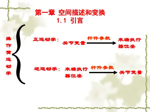
二、二、本课程的教学内容和基本要求1.1.绪言简述机器人学的起源与发展,讨论机器人学的定义,分析机器人的特点、结构与分类。
2.2.机器人学的数学基础空间任意点的位置和姿态变换、坐标变换、齐次坐标变换、物体的变换和逆变换,以及通用旋转变换等。
3.3.机器人运动方程的表示与求解机械手运动姿态、方向角、运动位置和坐标的运动方程以及连杆变换矩阵的表示,欧拉变换、滚-仰-偏变换和球面变换等求解方法,机器人微分运动及其雅可比矩阵等4.4.机器人动力学机器人动力学方程、动态特性和静态特性;着重分析机械手动力学方程的两种求法,即拉格朗日功能平衡法和牛顿-欧拉动态平衡法;然后总结出建立拉格朗日方程的步骤5.5.机器人的控制机器人控制与规划6.6.机器人学的现状、未来包括国内外机器人技术和市场的发展现状和预测、21世纪机器人技术的发展趋势、我国新世纪机器人学的发展战略等。

•Point•Vector•Matrix•Calculus•Linear algebra •Dot product •Cross product •Position/Orientation •Rotation matrix •Direction cosine•Coordinate system •Frame•Mapping •Translation •Rotation •Homogeneous transorm •Cross product •Operator •Translational operator •Rotational operator•Transformation operator •Compound transformation •Inverting a transformChapter3 Manipulator Kinematics•What is kinematics ?Kinematics is the sciences of motion that treats the subject without regard to the forces that cause it.•Example:With the knowledge of manipulator’s link length and joint angles, how to compute the position and orientation of the manipulatorsIn kinematics, we consider about the position, the velocity,the acceleration, and the higher derivatives of the position.The study of kinematics refers to all the geometrical and time-based properties of the motion.•Forward kinematicsGiven the joint variables of the robot, determine the position and orientation of the end-effector.[]12...T n θθθΘ=),,,,,(αβγz y x Y =•Kinematic ChainA robot can be treated as a set of right bodies (rigid links) connected together at various joints.•Lower pair:describe the connection between a pair of bodies when relative motion is characterized by two surface sliding over on another.•Joint type (lower pair):1. Revolute2. Prismatic3. Cylindrical4. Planar5. Screw6. Spherical•We consider the joint with 1degree-of-freedom (DOF). A joint with m DOF can be modeled as m joints of 1DOF connected by m-1links of zero length.•The action of joint can be described by a single real number: the angle of rotation in the case of a revolute joint, or the displacement in the case of a prismatic joint.•Number of the links starts from the immobile base (link 0), the first moving body is link 1and so on, out to the freed end of the arm, which is link n .…link1link2link0link6•In kinematics, a link is considered as a rigid body that define the relationship between two neighboring joint axes.1−i a axis i-1axis ilink i-11−i α1−i α:twist angle•Two parameters: link length and link twist angle are used to define the relative location of the two axes.•L ink length: the distance between two axes is measured along a line that is mutually perpendicular to both axes. This line is unique except in the case that two axes are parallel.axis i-1axis ilink i-1a1−ia:link length1−i•Imagine that a plane, whose normal is the mutuallyperpendicular line just constructed, we can project the axis i-1and axis i onto that plane and measure the angle from axis i-1to axis i by the right-hand rule .axis i-1axis ilink n-11−i α:twist angle1−i a•Intermediate links in the chain:Neighboring links has a common joint axis between them. The distance along this common axis from one link to another is defined as “link offset”. It will be variable for prismatic joint.axis i-1axis ilink i-11−iαid1−iaiθiaid:link offset•The angle that rotates about this common axis between one link and its neighboring link is defined as “joint angle ”. It will be variable for revolute joint.axis i-1axis ilink i-11−i αid 1−i a iθia i θ:joint angle•Link length and link twist angle depend on joint axes i and i+1.•For first link in the chain, we set and .00=a 00=α•For last link in the chain, we set and .0=n a 0=n α•If joint 1 is revolute, is set to be 0, zero position ofwill be chosen arbitrarily.1d 1θ•If joint 1 is prismatic, is set to be 0; zero position ofwill be chosen arbitrarily.1θ1d•Link parameters¾For revolute joint, the joint angle is called “joint variable”, and the other three quantities are fixed link parameters.¾For prismatic joint, the link offset is called “jointvariable”, and the other three link quantities are fixed link parameters.θd •Any robot can be described kinematically by giving the values of four quantities for each link, i.e., Denavit-Hartenberg notation[]i i iid a θαvariableconstant• A frame is attached to each link to describe the location of a link relative to its neighbors.•The link frame are named by number according to the link to which they are attached. Step1: frame {i}link {i}link1link2link0link6{0}{1}{2}{6}•Step2: intermediate link in the chain:iZ ˆjoint axis i frame {i}axis i-1axis ilink i-11−i αid 1−i a iθia 1ˆ−i Z 1ˆ−i X 1ˆ−i Y iZ ˆiX ˆiY ˆlink i•Step 3: direction of -along , from joint i to joint i+1iX ˆi a axis i-1axis ilink i-11−i αid 1−i a iθia 1ˆ−i Z 1ˆ−i X 1ˆ−i Y iZ ˆiX ˆiY ˆlink i•Step 4: direction of can be determined by right-hand rule ˆiY•How about if intersect ?is normal to the plane of and .i Z ˆ1ˆ+i Z iX ˆi Z ˆ1ˆ+i Z •First link in the chainsSelection of frame {0} is arbitrarily, will be selected along .0ˆZ 1ˆZ •Last link in the chainsFor revolute joint is chosen along when , the origin of frame {n} is chosen to set . n X ˆ0=n d 1ˆ−n X 0=n θFor prismatic joint, the direction of is chose to make and the origin of {n} is chosen at the intersection of and joint axis n when .0=n θnX ˆ1ˆ−n X 0=n daxis i-1axis ilink i-11−i αid 1−i a iθia 1ˆ−i Z 1ˆ−i X 1ˆ−i Y iZ ˆiX ˆiY ˆlink i•Summary of link parameters: the distance from to measured along : the angle from to measured about : the distance from to measured along : the angle from to measured about iX ˆi a i αi Z ˆ1ˆ+i Z i Z ˆ1ˆ+i Z iX ˆi d i θ1ˆ−i X i X ˆi Z ˆ1ˆ−i X iX ˆi Z ˆ•Summary of link-frame attachment procedure:Step1: identify the join axis (revolute joint/prismatic joint)Step2: identify the common perpendicular between two neighbouring joint axes, at the point of where the common perpendicular meets the i-th axis, assign the link-frame origin. (special case: the two axes intersect)Step3: assign the axis pointing along the i-th joint axis Step4: assign the axis pointing along the common perpendicular (special case: the two axes intersect)iX ˆi Z ˆStep5: assign the axis to complete a right-hand coordinate system.iY ˆStep6: assign the {0} to match {1} when first joint variable is 0.For {n}, chosen origin and directly of freely, but so as to cause as many link parameters as possible to be zero.nX ˆExample 3.3 in the text book(a)(b)Example 3.4 in the text bookwhere two adjacentaxes intersect(a)(b)D-H Tablei1−i a 1−i αid i θ11ˆZ 1ˆX 2ˆZ 2ˆX 3ˆZ 3ˆX 2L Link1Link2Link323D 90000)(2t d 2L )(1t θ)(3t θFrame {0} is coincident with frame {1}.Example 3.5 in the text bookwhere two adjacentaxes intersect•It is possible that there is no unique attachment of frames to link and result in several possible D-H representation.¾There are two choice of direction in which to point .¾In the case of intersecting axes, there are two choices fordirection of . 2ˆZ iX ˆ01=a 901−=α01=d 22L a =02=α12L d =1ˆZ 1ˆX 2ˆZ 2ˆX 3ˆZ 1L 2L case 111()t θθ=22()t θθ=−1=a 901=α01=d 22L a =02=α12L d −=1ˆZ 1ˆX 2ˆZ 2ˆX 3ˆZ 1L 2L case 2•When the direction of is changed, some link parameters willalso be changed. There are four more possible assignments offrames with pointing down.1X 11()t θθ=22()t θθ=1ˆZ•The above problem will be broken into four sub-sub-problems.Each sub-sub problem will be a function of only one link parameter.[]i i i i d a θα11−−Ti i1−•Sub-problem: construct the transform that define frame {i} to frame {i-1}•Problem statement: solve for the position and orientation of link n relative to link 0.•The problem can be broken into n sub-problem. Each sub-problem will involve transformation from one link to its neighboring link.•Introduce three intermediate frames: {P}, {Q}, and {R} for each link for transformationaxis i-1axis ilink n-11−iαid1−iaiθia 1ˆ−iZ1ˆ−iXiZˆiXˆRZˆRXˆQXˆQZˆPZˆPXˆ•Step1: {i}--->{P}, translation transform•Step2: {P}--->{Q}, rotation transform•Step3: {Q}--->{R}, translation transform•Step4: {R}--->{i-1}, rotation transform)(ˆi z P id D T i =)(ˆi z Q Pi R T θ=)(1ˆ1−−=i X R Qa D T i )(1ˆ11−−−=i X i Ri R T α)()()()(ˆˆ1ˆ1ˆ111i Z i Z i X i X i id D R a D R T iii i θα−−−−−=We can write))()()((11T T T T T P iQ P R Q i R i i−−=⎥⎥⎥⎥⎦⎤⎢⎢⎢⎢⎣⎡−−−=−−−−−−−−−−10001111111111i i i i i i i i i i i i i i i i i i i d c c s c s s d s s c c c s a s c T αααθαθαααθαθθθBy substituting the link parameters into above equation, we have•The Unimation Puma 560 is a robot with 6 degree of freedom, and all rotational joints (6R).•The link frames are assigned in the position corresponding to all joint angles equal to 0.forearm•Join axes of joint 4,5,6 intersect at a common point, and the joint axes 4,5,6 are mutually orthogonal. This design is used in many industrial robot.Schematic of the 3R wrist of PUMA 560•Link parameters of the PUMA 560 is listed in the following D-H table.•Transformation of each link can be computed as follows:•The transformation of all six link:•For a manipulator with n DOF, the position of all the links can be specified with a set of n joint variable. This set is often called as joint vector.•The space of joint vectors is referred as joint space.•Cartensian space: position is measured along orthogonal axes, and orientation is described by the rotation matrix wespecified before.•Cartensian space is often called as task-oriented space or operational space.•In the case that joint is not actuated directly by actuator, and the position sensors are often located at the actuators, actuator position should be considered.•Actuator vector: a set of actuator position•Actuator space: the space of actuator vectorsActuator SpaceJoint Space Cartesian Space•Base frame {B}, or frame {0}. It is attached to a non-moving part of the robot, i.e., the base, sometimes called link 0link1link2link0link6{B}{W}{T}{S}{G}link1link2link0link6{B}{W }{T }{S}{G}•The station frame {S}, located in a task-relevant location. Sometimes is called universe frame , task frame or world frame . It is often specified with respect to frame {B} as:TS B S =}{link1link2link0link6{B}{W }{T }{S}{G}•The wrist frame {W}, attached to the last link of themanipulator (frame {N}). It is defined relative to the base frame {B} asTT W N B W 0}{==link1link2link0link6{B}{W }{T }{S}{G}•The tool frame {T}, attached to the end of tool that the robot isholding. It can be defined according to wrist frame {W}.TT W T=}{link1link2link0link6{B}{W}{T }{S}{G}•The goal frame is utilized to describe the location to which therobot is to move the tool. It is specified relative to the station frame {S}.TG S G=}{•Where is the tool?The problem is to locate the position and the orientation of the tool that the robot is holding.))(()(1T T T T W TB W BS ST −=}{}{S T →•Example of the assignment of standard frames:Thank You!。
DONG QiuhuangCollege of Mechanical and Electronic Engineering, FAFU.Mathematical BasisManipulator-Mechanism Design 2Mathematical basisIntroduction4and tools will be some sort of mechanism.How to define the manipulate mathematical quantities (数学量)that represent location of the body?IntroductionRigid Body Motion (刚体运动)Position andOrientation Mathematical Quantities (Coordinates)Velocities, Forces (速度和力)must define coordinate systems representation.Mathematical basisDescription (描述)83×1 position vector.DescriptionCatesian coordinate system (笛卡尔坐标系):9Description10Description of Orientations (姿态描述)position , but also need to describe its orientation in the space.DescriptionHow to describe the orientation of a body ?Description of Orientationsreference system.Description12Description of OrientationsDescription1314Description of OrientationsDescriptionDescription of OrientationsDescriptionObtain the projection of that vector onto the unit directions of its reference coordinate.Example:Compute the Rotation MatrixRotation about axisExample:Rotation about axis:Rotation about axis:Description of OrientationsDescription19Description20manipulator hand is a position DescriptionWe define such a entity which contain the pair of position and Mathematical basiscoordinate system .工具坐标系目标坐标系固定坐标系基座坐标系Mapping23Mathematics of changing descriptions of the same quantity from frame to frame.1. Translation(平移)已知S 点在坐标系{B}中的表达,那么在坐标系{A}中如何表达?242. Rotation (旋转)求矢量在坐标系{A}三个主轴上的投影。
机器人学导论chapter6Manipulator DynamicsOutlineIntroduction运动学控制Why do we need to study the dynamics 4Given a set of force or torques applied the manipulator, try to calculate how the manipulator Given a desired trajectory, try to find out the desired torque inputs to cause this motion. E.g.: ControlContents of Dynamics:5RobotTwo methods for formulating dynamics model :OutlineAcceleration of a Rigid Bodycalled linear acceleration /angular acceleration :Vectors of linear acceleration / angular acceleration can be described in different reference frame1.Linear acceleration of rigid body:9frame {A} and frame {B} have coincident origins, the velocity This form of the equation will be useful when deriving the corresponding acceleration equation.1.Linear acceleration of rigid body:10By differentiating1.Linear acceleration of rigid body:11origins are not coincident, we add one term which gives the origin of {B}:The above equation will be utilized to calculate thelinear acceleration of a manipulator (both revolute joint and prismatic joint). 2.Angular acceleration of rigid body: Consider that frame {B} rotate with respect to frame {A} with and frame {C} rotate with respect to frame {B} with , we can obtain:By differentiating:Applying equation (6.6):This equation will be utilized to calculate the angularacceleration of the links of a manipulator.Outline Mass DistributionMass Distributionexpressed in the following matrix form:whereMass moments of inertia Mass products of inertia Mass Distribution16As note, the inertia tensor is a functionof the location and orientation of thereference frame.{C}Where {C} is located at the center ofmass of the body.Mass Distributionwhereparallel-axis theorem:If the reference frame {C}(body frame) are selected such that theproducts of inertia being set to zero, the axes of this reference frameare called “principal axes(主轴)”, and the mass moment arenoted as “principal moments of inertia(主惯性矩)”.Outline1. Newton-Euler Dynamic Formulation 19rate of change of the linearmomentum is equal to theapplied forceLinear Momentum (动量) 1. Newton-Euler Dynamic Formulation 20Angular Momentum (角动量)Inertia Tensor1. Newton-Euler Dynamic Formulation where m is the mass of a rigid body, represent inertia tensor , F C is the external force on the center of gravity, N is the torque on the rigid body, v C represent the translational velocity , while ω is the angular velocity .2. Iterative (递推)Newton-Euler Dynamic Formulation 2.1 Compute velocities and accelerations Angular velocity from link to link:By differentiating:When joint i +1 is prismatic:2. Iterative (递推)Newton-Euler Dynamic Formulation The linear velocity of each link-frame origin:By differentiating: When joint i +1 is prismatic:The linear acceleration of the center of mass of each link:2. Iterative (递推)Newton-Euler Dynamic Formulation2. Iterative (递推)Newton-Euler Dynamic Formulation The torque-balance relationship for link i :2. Iterative (递推)Newton-Euler Dynamic Formulation 26Rearrange the force and torque equations:These equations are evaluated link by link, starting from linkn and working inward toward the base of the robot (inward force iterations ).2. Iterative (递推)Newton-Euler Dynamic Formulation As in the static case, the required joint torque are Found by taking the component of the torque Applied by one link on its neighbor: prismatic:2. Iterative (递推)Newton-Euler Dynamic Formulation 28Outward iterations: i: 0→n292. Iterative (递推)Newton-Euler Dynamic Formulation 2. Iterative (递推)Newton-Euler Dynamic Formulation Inward iterations: i: n →1移动关节转动关节2. Iterative (递推)Newton-Euler Dynamic Formulation32Newton-Euler Formulation of Manipulator Dynamics All mass exists as a point mass : The vectors that locate the Center of mass for each link:The inertia tensor for each link:33Newton-Euler Formulation of Manipulator Dynamics : There are no force acting on the end-effector:The base of the robot is not rotating:To include gravity force, we will use:34Newton-Euler Formulation of Manipulator Dynamics : The rotation between successive 35Newton-Euler Formulation of Manipulator Dynamics iteration for link 1:36Newton-Euler Formulation of Manipulator Dynamics iteration for37Newton-Euler Formulation of Manipulator Dynamics iteration for 38Newton-Euler Formulation of Manipulator Dynamics : The outward iteration for 39Newton-Euler Formulation of Manipulator Dynamics Example:Step 4: The outward iteration for link 2:40Newton-Euler Formulation of Manipulator Dynamics : The outward iteration for link 2:41Newton-Euler Formulation of Manipulator Dynamics : The inward iteration for 42Newton-Euler Formulation of Manipulator DynamicsNewton-Euler Formulation of Manipulator Dynamics 44Newton-Euler Formulation of Manipulator Dynamics torque: Written in Matrices Form:Newton-Euler Formulation of Manipulator Dynamics Example:有效惯量(effective inertial):关节i 的加速度在关节i 上产生的惯性力Newton-Euler Formulation of Manipulator Dynamics 耦合惯量(coupled inertial):关节i,j 的加速度在关节j ,i 上产生的惯性力Newton-Euler Formulation of Manipulator Dynamics 向心加速度(acceleration centripetal)系数关节i,j 的速度在关节j ,i 上产生的向心力Newton-Euler Formulation of Manipulator Dynamics 哥氏加速度(Coriolis accelaration)系数:关节j,k 的速度引起的在关节i 上产生的哥氏力(Coriolis force)Newton-Euler Formulation of Manipulator Dynamics 重力项(gravity):关节i,j 处的重力OutlineLagrangian Formulation of Manipulator Dynamics 51Lagrangian Formulation of Manipulator Dynamics522-links manipulatorand Potential Energy Lagrangian Formulation of Manipulator Dynamics 53Example:2-links manipulatorKinetic Energy K 2 and Potential Energy P 2 of link 2:where Lagrangian Formulation of Manipulator Dynamics542-links manipulatorLagrangian Formulation of Manipulator Dynamics55OutlineFormulation Manipulator Dynamics in Cartesian Space The above dynamic equations is developed interms of the manipulator joint angles (jointspace).We could use the serial-link nature ofmechanism to advantage in deriving theequations.Sometimes, it might be desirable to express thedynamics with respect to Cartesian variablesform.57Formulation Manipulator Dynamics in Cartesian Space58 whereSummarySummarize steps to form Lagrangian Equation of n-link。

Introduction to Robotics(机器人学导论)School of Electrical Engineering and AutomationTianjin UniversityFall Semester, 2010•Time: Monday Night(Room 115, Section A,Building No. 26)Week 1st to Week 8th•Instructor: Dr. Xian, Bin (鲜斌)•Office: Room 525, Section E, Building No.26•Office Hours: 3:00 pm to 5:00 pm, Wednesday •E-mail : xbin@•Text Book and Reference Books1.John J. Craig, Introduction to Robotics: Mechanics AndControl, Third Edition, Pearson Education, 2005.约翰J. 克拉格,机器人学导论,机械工业出版社,2006.¥49$732.Saeed B. Niku, 机器人学导论-分析、系统及应用,孙富春等翻译,电子工业出版社,2004.3. Mark W. Spong, M. Vidyasagar, Robotics and Control, John Wiley& Sons, 2004.•Grading: Homework 20%Final exam 80%•Course Outline1.Background and Introduction2.Rigid Motion and Homogeneous Transformation3.Forward Manipulator Kinematics4.Inverse Manipulator Kinematics5.Velocity Kinematics6.Manipulator Dynamics7. Control of ManipulatorsChapter 1 IntroductionHollywood’s RobotsR2-D2T800Ch1.1Background1. What is a robot?By general agreement, a robot is:A programmable machine that imitates the actions orappearance of an intelligent creature–usually a human.A robot (industrial robot) is a reprogrammable,multifunctional manipulator designed to move materials, parts, tools, or specialized devices, through variable programmedmotions for the performance of a variety of tasks.(definition from Robotics Institute of American)¾ A Robot is controlled by a computer or similar device.¾ A Robot can be easily re-programmed.2.JIRA Standards for Robot¾Human-Controlled System¾Fixed Sequence Robot¾Alterable Sequence Robot¾Playback RobotRIA ¾Numerical Controlled Robot¾Intelligent Robot•Type of robots¾Robot Manipulator¾Ground Mobile Robot¾Under Water Robot¾Humanoid Robot3.What is Robotics?¾Robotics is the technology and knowledge that are used for design and application of robots.4.Robotics is a interdisciplinary research area:¾Mechanical Engineering: methodologies for the study of machine in static and dynamic situation …¾Electrical Engineering: design of sensor, actuator, interface, control algorithms, ….¾Computer Sciences: software, vision, intelligence….¾Mathematics¾BiologyCh1.2History of Robotics1.1922, Karel Capkef’s novel “Rossum’s Universal Robots”,--Rabota2.1952, First Numerical Control Machine Tool by MIT3.1954, First Re-programmable Robot by George Devol4.1955, Homogeneous Transformation by Denavit &Hartenberg5.1962, First Industry Robot by Unimation6.1968, First Intelligent Robot (Shakey)by SRI7.1972, Cartesian Space Robot by IBM (to IBM7565 Robot)8.1973, T3 Robot by Cincinnati Mialcron9.1978, PUMA Robot by Unimation10.1983, Robotics course were provided in many universitiesStanford Research Institute ---ShakeyUnimation-Puma RobotCh1.3Components of Robot •What a robot will contain?1.Manipulator or Mobile Vehicle2.End-effector3.Actuator: Servo Motor, Stepper Motor, HydraulicCylinder…4.Sensor: Resolvers/Potentiometers, Tachometer, StrainGauge, Encoder…5.Controller6.Processor7.Software: OS, Robot Software, Application Routines …Ch1.4Architecture of RobotEnvironmental sensors Motionplanner ControllerMechanicalStructureConfigurationsensorProcessorPower Supply CommunicationUser InterfaceCh1.5DOF of Robot•The Number of degree of freedom: the number of independent position variables that would have to bespecified in order to locate all the parts of the mechanism.•How to determine the location of a point in three dimension space?•How to determine the location of a rigid objective in three dimension space?Both position and orientation of the objective are needed!•For the robot with DOF greater than 6, there is no identical solution for the system.•What is the number of DOF for human’s arm?•Due to the structure of actuator, there is limited DOF, i.e,0.5 DOF.A B•Number of DOF for robot is determined by its application,i.e, robot for PCB assembly often has 3.5 DOFCh1.5Robot Joints•Main types: Rotary Joint, Prismatic Joint, and Ball Joint•It is customary to classify robots of kinematically simple class according to the design of their joints(the positioningstructure).•P: Prismatic JointR: Rotary JointS: Ball Jointi.e, 3P3R, 2RSCartesian (3P)Cylindrical (R2P)Spherical(2RP)Articulated (3R)SCARA: Selectively Compliant Assembly Robot ArmAdept Cobra s350 (2RP)Ch1.7Performance of Robot •Load Capacity: depends upon the size of its structural members, power-transmission systems and actuator. Example: Adept S1700 6 Axis Robot, Wight 280kg, payload 10kg(rate)/20kg(maximum)•Workspace: The maximum distance that the robot can reached within its working area.•Speed: be determined by robot’s application.•Accuracy: how accurately a robot can reach its destination, some industry robots can meet 0.001 inch ( or 0.0254mm) or higher accuracy.•Repeatability: the accuracy for a robot to reach the same destination for given times, most industry robots can reach0.001 inch or higher level.Ch1.8Application of Robot •Installed Industry Robots•Industry¾Welding¾Painting¾Assembly¾Pick and Place¾Diagnosis•Biotechnology¾Micro/Nano Manipulation¾Sample Handling¾Automated Analysis•MedicalSurgery, Rehabilitation ….•Military Application ¾Reconnaissance¾Battle field fighting¾Search¾Rescue•Space ExplorationMars Exploration Rovers: twin robot geologist, landed on Mars on Jan 3and 4, 2004Chinese Lunar Rovers: test inthe desert•EntertainmentSony QrioSony I-sobot RobotHonda ASIMOSony Qrio ---Fan DanceCh1.9Robot Coordinate System •Global Reference Coordinate System (frame)XY Z•Joint Reference Coordinate System (frame)XYZ(base)1θ2θ3θ•Tool Reference Coordinate System (frame)XYZ(base)X1Y1Z1Ch1.10Forward Kinematics •Kinematics: the science of motion that treats motion without regard to the forces which cause it.•Within the sciences of kinematics, we study position, velocity, acceleration and all higher derivative of theposition variables.•Kinematics refers to all the geometrical and time-based properties of the motion.•Forward kinematics: static geometrical problem of computing the position and orientation of the end-effector of the manipulator.•Given a set of joint angles, how to compute the position an orientation of the tool frame relative to the base frame.XYZ(base)X1Y1Z11θ2θ3θ•Inverse Kinematics: given the position and orientation of the end-effector, calculate all possible set of joint angles that could be used to attain this specified position and orientation.XYZ(base)X1Y1Z11θ2θ3θCh1.11Inverse Kinematics•This problem can be considered as a mapping of locations in external 3-D Cartesian space to locations in the robot’sinternal joint space.•The inverse kinematics problem is more complicate than the forward kinematics¾The kinematic equations are nonlinear, the solutionprocedure is not always easy.¾Existence of the solution? and multiple solution?Ch1.12Velocity Kinematics •Velocity Kinematics: derive the velocity relationship, relating the linear and angular velocities of the end-effector (or any other point on the robot) to the joint velocitiesXYZ(base)vw3θ2θ1θ•Jacobian Matrix: specifies a mapping from velocities in the joint space to velocities in the Cartesian space.•The nature of this mapping changes as the configuration of the robot varies.•Singularities: at certain points, the mapping is not invertible.Ch1.13Robot Dynamics •Dynamics: study devoted to study the force required to cause motion.XYZ(base)AV 1τ2τ3τ•The exact form of the required actuator torquedepends on mass properties of the robotlink/payload, the attributes of the path taken by the end-effector.•Robot dynamic mode can be utilized in¾calculating the desired actuator torque functionto drive the robot to follow desired trajectory¾simulationCh1.14Robot Control•Why need to consider robot control problem?¾The vast majority of manipulator are driven byactuators that supply a force or a torque to cause themotion of robot.¾An algorithm is needed to compute torque/force thatwill caused the desire motion.•Linear position control: control algorithm design based on linear approximations to the dynamics of a robot.•Nonlinear position control: control algorithm design based on the nonlinear dynamics of a robot.Ch1.15Summary •Definition and classification of robot •History of robot•Structure of robot•Application of robot•Basic concepts of robotics•Research on open problem¾Manipulation, Locomotion¾Navigation, Control¾Learning an Adaptation (AI)¾Human-Robot Interaction¾Biologically inspired robotThank You!。
S OLUTIONS M ANUALI NTRODUCTION TOR OBOTICSM ECHANICS AND C ONTROLT HIRD E DITIONJ OHN J.C RAIGUpper Saddle River, New Jersey 07458Associate Editor: Alice DworkinExecutive Managing Editor: Vince O'BrienManaging Editor: David A. GeorgeProduction Editor: Craig LittleSupplement Cover Manager: Daniel SandinManufacturing Buyer: Ilene Kahn©2005 by Pearson Education, Inc.Pearson Prentice HallPearson Education, Inc.Upper Saddle River, NJ 07458All rights reserved. No part of this book may be reproduced in any form or by any means, without permission in writing from the publisher.The author and publisher of this book have used their best efforts in preparing this book. These efforts include the development, research, and testing of the theories and programs to determine their effectiveness. The author and publisher make no warranty of any kind, expressed or implied, with regard to these programs or the documentation contained in this book. The author and pub-lisher shall not be liable in any event for incidental or consequential damages in connection with, or arising out of, the furnishing, performance, or use of these programs.Pearson Prentice Hall®is a trademark of Pearson Education, Inc.This work is protected by United States copyright laws and is provided solely for the use of instructors in teaching their courses and assessing student learning. Dissemination or sale of any part of this work (including on the World Wide Web) will destroy the integrity of the work and is not permitted. The work and materials from it should never be made available to students except by instructors using the accompanying text in their classes. All recipients of this work are expected to abide by these restrictions and to honor the intended pedagogical purposes and the needs of other instructors who rely on these materials.Printed in the United States of America10 9 8 7 6 5 4 3 2 1ISBN 0201-54362-1Pearson Education Ltd., LondonPearson Education Australia Pty. Ltd., SydneyPearson Education Singapore, Pte. Ltd.Pearson Education North Asia Ltd., Hong KongPearson Education Canada, Inc., TorontoPearson Educación de Mexico, S.A. de C.V.Pearson Education—Japan,TokyoPearson Education Malaysia, Pte. Ltd.Pearson Education, Inc., Upper Saddle River, New Jersey。
机器人学导论:分析、控制及应用(第二版)
《机器人学导论:分析、控制及应用(第二版)》是由日本机器人学大师Tomizuka Masayoshi编写的一本机器人学教材,旨在介绍机器人的基本原理、运动学、动力学、控
制技术等方面的知识。
本书内容详实、全面,适合机器人学、控制工程、机械工程、自动
化等专业的学生和从业人员学习使用。
本书主要分为四个部分,分别介绍机器人的基本概念、机器人的运动学和动力学、机
器人的控制技术以及机器人的应用。
其中基本概念包括机器人的概述、机器人的结构、运
动规划、感知与反馈等方面;运动学和动力学包括机器人的运动学、力学、运动控制等方面;控制技术包括机器人的控制模型、控制策略、控制算法、力控制、触觉反馈等方面;
应用包括机器人的应用领域、工业机器人、服务机器人、医疗机器人、一体化机器人等方面。
本书作者根据自己多年的教学和研究经验,整理出了系统而严谨的机器人学知识体系,涉及了机器人运动规划、运动控制、力控制、感知与反馈等方面。
同时,本书也涉及了一
些最新的机器人应用领域,比如服务机器人、医疗机器人以及一体化机器人等。
通过本书
的学习,读者不仅能够掌握机器人学的基本理论和知识,还能够了解最新的机器人应用趋势,提高自身的机器人应用技能。
总之,《机器人学导论:分析、控制及应用(第二版)》是一本很好的机器人学教材,不仅对于学生的学习有很大的帮助,对于从业人员的工作也有很大的指导作用。
好的学习
文献能够帮助我们更好地了解机器人学的基本概念、原理和应用,从而在未来的机器人领
域中更好地创造和创新。
天津大学本科课程描述
(表格内容:题头为加黑小四号宋体,内容为普通小四号宋体,1.5倍行距)学院:电气与自动化工程专业名称:自动化
本科课程信息
课程名称:机器人学导论(双语) 课程编号:2030373
学分: 2 学时:32
课程描述:本课程为双语教学课程,是针对自动化专业本科生开设的专业选修课。
本课程主要学习有关机器人的基础知识、机器人运动与齐次变换、机器人正/逆运动学、机器人速度运动学、机器人动力学等内容。
通过本课程的学习,使学生对机器人学的基础知识有一个全面的理解和应用,同时能够掌握基本的机器人学英语术语。
课程名称:机器人学导论(双语) 课程编号:2030373 学分: 2 学时:32
课程描述:本课程为双语教学课程,是针对自动化专业本科生开设的专业选修课。
本课程主要学习有关机器人的基础知识、机器人运动与齐次变换、机器人正/逆运动学、机器人速度运动学、机器人动力学等内容。
通过本课程的学习,使学生对机器人学的基础知识有一个全面的理解和应用,同时能够掌握基本的机器人学英语术语。
Course Description
(表格内容:题头为加黑小四号Times New Roman,内容为普通小四号Times New Roman,1.5倍行距)
School:School of Electrical
Engineering and
Automation
Major:Automation Engineering
Information of undergraduate courses:
Title:Introduction of Robotics Code:2030373 Credit points:32 Hours: 2
Course Description: Spatial description of rigid body, homogeneous transformation; link description of robot manipulator, the derivation of D-H table; the solvability of inverse kinematics problem, examples of PUMA 560 robots' inverse kinmeatics; linear and angular velocity of rigid bodies, derivation of Jacobian matrix; using Larange and Netwon-Euler methods to calculate dynamic equations for a rigid body
Title:Introduction of Robotics Code:2030373 Credit points:32 Hours: 2
Course Description: Spatial description of rigid body, homogeneous transformation; link description of robot manipulator, the derivation of D-H table; the solvability of inverse kinematics problem, examples of PUMA 560 robots' inverse kinmeatics; linear and angular velocity of rigid bodies, derivation of Jacobian matrix; using Larange and Netwon-Euler methods to calculate dynamic equations for a rigid body。