比博士RS5调节说明书
- 格式:docx
- 大小:10.78 KB
- 文档页数:1
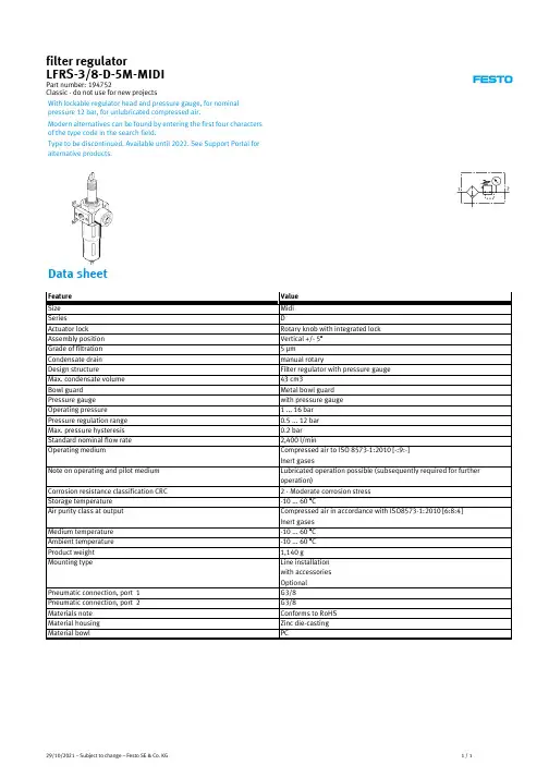
文件名称:雷赛交、直流伺服驱动器调试说明书 文件版本:中文简体A4版文件页数:共 36 页(含此页)日 期:2009年7月18日深圳市雷赛机电技术开发有限公司1地址(Address):深圳市南山区登良路25号天安南油工业区二栋三楼雷赛交、直流伺服驱动器调试说明书(版本:中文简体A4版)深圳市雷赛机电技术开发有限公司w 2地址(Address):深圳市南山区登良路25号天安南油工业区二栋三楼地址(Address):深圳市南山区登良路25号天安南油工业区二栋三楼3声 明版权所有 © 深圳市雷赛机电技术开发有限公司 保留一切权利。
未经深圳市雷赛机电技术开发有限公司的许可,任何组织和个人不得擅自摘抄、复制文档内容的部分或全部,并不得以任何形式传播。
商标声明商标为深圳市雷赛机电技术开发有限公司的注册商标,并对其享有独占使用、许可使用、转让、续展等各项法定权利,未经深圳市雷赛机电技术开发有限公 司允许,任何组织或个人不得在商品上使用相同或类似的商标。
注意在所规定的支持保修范围内,深圳市雷赛机电技术开发有限公司履行承诺的保修服务,超出所在规定的保修范围的,恕不承担保修服务。
对于在使用本产品过程中可能造成的损失,深圳市雷赛科技有限公司不承担相关责任。
如发生任何争议,应按中华人民共和国的相关法律解决。
深圳市雷赛机电技术开发有限公司随时可能因为软件或硬件升级对使用说明书的内容进行更新,所有这些更新都将纳入使用说明书新的版本中,恕不另行通知。
地址(Address):深圳市南山区登良路25号天安南油工业区二栋三楼4前 言版本说明本资料对产品的工作原理、安装方法、操作使用、故障排除、运输储存、维护保养等进行说明。
如果你是第一次使用该产品,请在安装使用之前仔细阅读此资料。
请妥善保管此资料,以便将来查阅参考。
符号说明为了预防可能对人体造成的伤害或设备损坏,本使用说明书用以下安全标志加以提示,在使用设备时请注意标志提示的内容,以确保您和周围人员的安全以及正确使用设备。
Electric Drivesand Controls Hydraulics Linear Motion andAssembly Technologies Pneumatics ServiceRexroth变频器VFC 3610 / VFC 5610R912005517版本04快速启动指南Bosch Rexroth AG VFC 3610 / VFC 5610更改过程出版颁发日期备注DOK-RCON04-VFC-x610***-QU01-ZH-P2014.04第一版DOK-RCON04-VFC-x610***-QU02-ZH-P2014.05机型扩展DOK-RCON04-VFC-x610***-QU03-ZH-P2014.05新功能DOK-RCON04-VFC-x610***-QU04-ZH-P2014.06新功能关于此文档该《快速启动指南》基于产品《使用手册》,《使用手册》包含产品的详细数据。
在未通读产品《使用手册》中的安全相关章节内容以及产品标准供货所附《安全说明》前,请勿操作该产品。
参考文档如需其他类型或语言的文档,请联系当地代理商或访问以下网址:/vfcx610版权© 博世力士乐(西安)电子传动与控制有限公司 2014该文档以及其中的数据、技术规格和其它信息均为博世力士乐(西安)电子传动与控制有限公司的专有财产。
未经同意,禁止复制或供第三方使用。
责任规格数据仅用于产品说明,如果未在合同中明确规定,不得视为对特性的保证。
本公司保留关于该文档内容和产品可用性的所有权利。
RS-3c2d36fafe071a120a6846a5015a435a-4-zh-CN-3VFC 3610 / VFC 5610 Bosch Rexroth AG目录目录页数1 结构安装 (1)1.1 目视检查 (1)1.2 环境条件 (1)1.3 安装条件 (2)1.4 外型和尺寸 (3)1.4.1 外型 (3)1.4.2 尺寸 (4)1.4.3 DIN导轨安装 (5)2 电气连接 (6)2.1 电气连接概述 (6)2.2 电缆规格 (7)2.2.1 主回路配线 (7)2.2.2 控制回路配线 (8)2.3 端子 (9)2.3.1 主回路端子 (9)2.3.2 控制回路端子 (11)控制回路端子示意 (11)控制回路端子说明 (11)数字输入X1...X5 NPN / PNP接线方式 (13)数字输出DO1a、DO1b负载上拉 / 下拉接线方式 (14)模拟输入端子(AI1、AI2、+10 V、+5 V、Earth和GND) (14)3 起动 (15)3.1 LED操作面板和防尘盖 (15)3.1.1 LED操作面板 (15)3.1.2 防尘盖 (16)3.1.3 LED指示灯 (17)3.1.4 操作说明 (18)3.2 起动过程 (19)3.2.1 通电前检查 (19)3.2.2 通电后检查 (19)3.2.3 检查起动参数 (20)3.2.4 控制电机 (21)3.2.5 电机参数自动整定 (22)3.3 参数列表 (23)3.3.1 参数列表中术语和缩写 (23)DOK-RCON04-VFC-x610***-QU04-ZH-P I页数3.3.2 b 组: 系统参数....................................................................................... 23b0: 基本系统参数................................................................................... 233.3.3C 组: 功率参数....................................................................................... 24C0: 功率控制参数.................................................................................. 24C1: 电机和系统参数............................................................................... 25C2: V/f 控制参数.................................................................................... 26C3: 矢量控制参数.................................................................................. 273.3.4E 组: 功能控制参数................................................................................. 28E0: 控制与设定参数............................................................................... 28E1: 输入端子参数................................................................................... 31E2: 输出端子参数................................................................................... 33E3: 多段速与简易PLC 参数.................................................................... 35E4: PID 控制参数................................................................................... 36E5: 扩展功能参数................................................................................... 37E8: 标准通讯参数................................................................................... 37E9: 保护与故障参数............................................................................... 383.3.5U 组: 操作面板参数................................................................................ 40U0: 操作面板通用参数............................................................................ 40U1: LED 操作面板参数........................................................................... 403.3.6 d 组: 监视参数....................................................................................... 414 诊断...................................................................................................... 424.1 状态代码............................................................................................... 424.2 警告代码............................................................................................... 424.3故障代码 (43)Bosch Rexroth AG 目录VFC 3610 / VFC 5610II DOK-RCON04-VFC-x610***-QU04-ZH-PVFC 3610 / VFC 5610 Bosch Rexroth AG结构安装1 结构安装1.1 目视检查打开变频器包装后,请进行详细目视检查。
FMR56FMR57操作说明一.外观及基本操作1.FMR56和FMR57的外观相似,都是矩形的设计,机身上有LCD显示屏和按键。
2.按键说明:主要按键包括电源开/关键、频道调节键、音量调节键和模式选择键等。
3.开机与关机:长按电源开/关键开启或关闭收音机。
4.频道调节:按频道调节键可以实现对电台频道的切换,同时LCD屏幕上会显示当前频道号。
5.音量调节:按音量调节键可以实现音量大小的增加和减小,同时LCD屏幕上会显示当前音量大小。
6.模式选择:按模式选择键可以切换收音机的不同模式,例如FM收音、AM收音以及录音等。
二.FM收音模式1.进入FM收音模式:按模式选择键切换至FM模式,即可进入FM收音界面。
2.自动电台:按住频道调节键数秒,收音机会自动当前区域可接收的FM电台,并保存在存储空间中。
3.手动电台:单击频道调节键可以实现手动电台,每次单击都会切换到一个新的频道。
4.保存电台:在FM模式下,长按频道调节键即可将当前电台保存在收音机的存储空间中。
5.进入已保存电台:在FM模式下,按频道调节键可以切换到已保存的电台。
6.调节音量:按音量调节键可以实现FM收音的音量调节。
三.AM收音模式1.进入AM收音模式:按模式选择键切换至AM模式,即可进入AM收音界面。
2.自动电台:按住频道调节键数秒,收音机会自动当前区域可接收的AM电台,并保存在存储空间中。
3.手动电台:单击频道调节键可以实现手动电台,每次单击都会切换到一个新的频道。
4.保存电台:在AM模式下,长按频道调节键即可将当前电台保存在收音机的存储空间中。
5.进入已保存电台:在AM模式下,按频道调节键可以切换到已保存的电台。
6.调节音量:按音量调节键可以实现AM收音的音量调节。
四.录音模式1.进入录音模式:按模式选择键切换至录音模式,即可进入录音界面。
2.录音开始与结束:按下电源开/关键可开始录音,再次按下可结束录音。
3.保存录音:录音结束后,按频道调节键即可将录音保存在收音机的存储空间中。
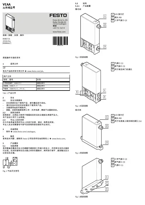
原版操作手册的译本1适用文件有关产品的所有可用文件 è /pk。
用户文件名称,型号目录H 导轨安装件,VAME-P7-T 装配说明书安装板,VAME-P...-Y装配说明书气路条,VABM-P6-15.../-P7-18...装配说明书Tab. 1 产品文件2安全2.1安全注意事项–仅在原装状态下使用产品,请勿擅自进行改动。
–请仅在技术状态完好的情况下使用本产品。
–注意使用地的环境条件。
–装配、安装和维修保养工作:关闭电源,确保不会重新启动。
2.2按规定使用按照规定,比例压力阀用于根据给定的设定点值按比例调节压力。
本产品设计用于工业领域。
2.3专业人员的资质仅允许由具备资质的专业人员进行安装、调试、保养及拆卸。
专业人员必须掌握电气和气动控制系统安装的专业知识。
3详细信息–附件 è /catalogue 。
4服务若有技术问题,请联系 Festo 公司在您所在地的联系人è 。
5产品概览5.1功能原理其所配备的集成式压力传感器可感测到工作接口的压力,并将其与设定点值进行比较。
在实际值和设定点值之间存在偏差时,阀将进行调节,直到输出压力达到设定点值。
Fig. 1 气动开关符号5.2结构5.2.1产品配置管式阀1LED 指示灯2插头 M83工作气接口 (2)Fig. 2前部视图1气源口 (1)2排气接口 (3)3用于固定阀门的通孔Fig. 3 后部视图板式阀1LED 指示灯2插头 M83用于在底座上固定阀的通孔 (2x)Fig. 4 前部视图1工作气接口 (2)2排气接口 (3)3气源口 (1)Fig. 5 底部视图8080724VEAA比例调压阀80807242018-05a [8080667]Festo AG & Co. KG Ruiter Straße 82 73734 Esslingen 德国+49 711 347-0 5.2.2产品派生型特性型号代码说明基本功能VEAA 压电式比例调压阀L 管式阀阀类型B 板式阀阀功能3三位三通阀,常闭D20 … 2 bar D90 … 6 bar 压力范围D110 … 10 bar F 法兰/底座气接口Q4快插接头 4 mm V1电压型 0 … 10 V 额定值输入和实际值输出A4电流型 4 … 20 mA 额定工作电压124 V DC 电接口R1插头 M8,4 针Tab. 2 产品派生型6运输和存放–在干燥、防紫外线、防腐蚀的环境中存放本产品。

Maintenance ManualA Regal BrandIntroductionThe PM500 is an encapsulated electronic voltage regulator intended for use with the Marathon PMG systemand most Marathon AC generators. The PM500 controls the output of a brushless AC generator by regulating the DC current input to the exciter field. The PM500 is designed as a three phase or single phasetrue RMS sensing regulator that is capable of accepting analog voltage adjustment input. The PM500 is UL Recognized and UL Certified for Canada – Component per UL File E222903. The PM500 bears the CE markfor the European Union.SpecificationsSensing Input175 - 600Vac, True RMS, 60/50Hz, 3 Phase/1 PhasePower Input 175 - 260Vac, 300Hz PMG, 60/50Hz ShuntPower Output, Continuous 85Vdc at 3.5Adc with 240Vac input powerPower Output, Forcing 170Vdc at 7Adc for 10 sec. with 240Vac input powerFuse 5 x 20mm S505-5A, Slow Blow TypeVoltage Regulation ± 0.25%, with 4% engine governingExcitation Resistance9 ohms, minimumOver Excitation Protection Excitation exceeds 190Vdc or 7Adc for more than 10 seconds Manual Voltage Adjustment Range ± 20% with 2000 ohm rheostat± 10% with 1000 ohm rheostatAnalog Voltage Input A1 & A2 ± 20% with 0-10Vdc or ± 5Vdc biasUnder Frequency Factory Setting 58Hz preset for 60Hz operation and 48Hz preset for 50Hz operation Voltage Build-up Voltage build up from input voltage ≥ 5Vac at 25Hz.Response Time<1 CycleWeight16.6 oz.Operating Temperature -40°C to +60°CStorage T emperature -40°C to +85°CPower Dissipation12 watts, maximumSize 5.9” L x 5.3” W x 2.2” HThermal Drift 0.05% / °C change in AVR ambient temperature Electromagnetic Compatibility TestsImmunityIEC61000-4-2 - Electrostatic DischargeIEC61000-4-3 - Radiated RFIEC61000-4-4 - Electrical Fast TransientIEC61000-4-5 - SurgeIEC61000-4-6 - Conducted RFIEC61000-4-11EmissionEN61204-3 - Conducted RFCISPR 22IEC61000-3-2 - Harmonic IECIEC61000-3-3 - Flicker IEC2InstallationMOUNTINGThe PM500 is mounted through a keyed hole in the generator conduit box and secured with a plastic mounting nut.The PM500 should be mounted directly to the conduit box panel with the rubber gasket positioned between the outside of the conduit box panel and the mounting nut.Protect front panel adjustment pots by installing clear or black plastic cover.Mounting nut torque is 26 – 43 lbf-in. Refer to the Figure 1 for dimensions.Wiring and ConnectionsEXCITER FIELD POWER CIRCUITThe exciter field resistance must be ≥ 9 ohms.If the exciter field resistance is less than 9 ohms andthe full load field current does not exceed 3.5 amps, add a resistor in series of sufficient wattage to increase the total resistance to 9 ohms.Connect the generator F+ (F1) field lead to the regu- lator F+ terminal. Connect the generator F- (F2) field lead to the regulator F- terminal. Refer to Figure 3 for typical connection points.POWER I NPUT C IRCUITThe PM500 is designed to be powered by a PMG and capacitor. A 7.5µƒ capacitor is connected in parallel between the PMG leads and the regulator power input terminals.The regulator power input terminals are labeled P1 and P2. Connect leads from P1 and P2 to the capacitor terminals.Connect regulator terminals P1 & P2 to generator leads that will provide 240Vac output. No capacitor is used with the PM500 in shunt mode.Refer to Figure 3 for typical connection points.Figure 23TO PREVENT PERSONAL INJURY OR EQUIPMENT DAMAGE, ONLY QUALIFIED PERSONNEL SHOULD INSTALL, OPERATE OR SERVICE THIS DEVICE.Figure 1Wiring and Connections (cont’d)Figure 3a – Three PhaseFigure 3b – Single PhaseSENSING CIRCUITSSensing input range is 175 - 600Vac. DIP switch SW1 and SW2 must be set appropriately. Refer to Figures 3a & 3b for typical connections.Single Phase SensingConnect PM500 terminal E1 to output lead L1 and E2 to output lead L2. PM500 terminal E3 is jumpered to E2. 3 Phase SensingConnect PM500 terminal E1 to output lead L1, E2 to output lead L2 and E3 to output lead L3.If used in a paralleling application, a paralleling CT will be required in the generator B phase. Paralleling CT must be sized to provide either a 1A or 5A signal when the generator is under full load.4Wiring and Connections (cont’d)DIP SWITCH PROGRAMMINGEight DIP switches located on the back of the regulator must be set appropriately for correct regulator operation and generator control. Refer to Figure 4.Switches 1 & 2 set the regulator sensing range.Switches 3 – 8 Configure multiple functions: 3 or Single Phase Sensing, Frequency, Over Excitation Protection, kW Range and Paralleling CT Range.SW1 : OFF SW2 : OFF Volts ≤ 280VacSW1 : OFF SW2 : ON Volts ≤ 480VacSW1 : ON SW2 : ON Volts ≤ 600VacOFF ONSW3 : 3 Phase Sensing 1 Phase SensingSW4 :60 Hz 50 HzSW5 :O/E Protect On O/E Protect OffSW8 :CT 1A CT 5ASW6 : OFF SW7 : OFF< 90kWSW6 : ON SW7 : OFF90 - 500kWSW6 : ON SW7 : ON> 500kW PROTECTION F UNCTIONSThe PM500 has built in protection functions for Over Excitation, Under Frequency and Over Voltage Protection.Over ExcitationThe Over Excitation function protects the PM500 and generator components in the event the excitation system demands excessive levels of voltage and/or current to maintain output.The Over Excitation function will trip when excitation output exceeds 190Vdc or 7Adc for more than 10 sec. with 220Vac input power.The Over Excitation O/E LED on the front panel will be illuminated when thePM500 when the OverExcitation system has tripped. Replace the fuse on theback panel if required and inspect the generator. ThePM500 will reset when power is cycledUnder FrequencyUnder Frequency protection allows the generatorvoltage to decrease when the output frequency dropsbelow the Roll-Off point. This reduces the load on theengine, allowing engine RPM to recover. This is normaloperation and no reset is required.5 Figure 4Operating AdjustmentsSix adjustable potentiometers are accessible on the front panel of the PM500. These are: VOLT, STAB, U/F, DIP, DROOP and TRIM.Figure 6VOLTAGE ADJUST (VOLT)Set PointOutput voltage may be adjusted via the VOLT poten- tiometer on the front panel of the regulator. The set point range is 175 - 600Vac.Remote Voltage AdjustA 2000 ohm, 2 watt rheostat may be connected to VR1 and VR2 - replacing the factory jumper, providing a ±10% voltage adjustment range. T erminals A1 & A2 may not be used when a rheostat is installed.Analog Voltage AdjustRegulator terminals A1 & A2 may be connected to the analog output of a gen-set controller. The allowable voltage input range is 0-10Vdc or ± 5Vdc will provide a 20% range. Jumper VR1 & VR2 when analog voltage adjustment terminals are used.TRIM ADJUST (TRIM)The analog bias range is adjusted via the TRIM potenti-ometer on the front panel. Set the TRIM potentiometer fully clockwise to provide a ± 20% adjustment range. DROOP ADJUST (DROOP)Requires a 1A or 5A CT in the B Phase.DIP switch SW8 must be set appropriately.In a paralleling system, the PM500 adjusts the genera- tor output voltage when the B phase current leads or lags the B phase voltage.The adjustment range may be preset via the DROOP potentiometer. The default setting is full counter clock-wise for minimum range. Maximum range is ±7% at 1.7 PF lagging to 0.7 PF leading.UNDER FREQUENCY ROLL-OFF ADJUST (U/F) The Roll-Off point is the frequency at which the gen- erator output voltage is allowed to decrease and is factory preset at 57Hz for 60Hz operation and at 47Hz for 50Hz operation.When the U/F LED on the front panel it lit, the PM500 is operating in Under Frequency mode.To change the roll-off point, first verify that the gen-set is operating at the intended speed and voltage.Fixed Engine RPMOn most new engines (Tier 4i and up), the engine speed is fixed at 1800RPM or 1500RPM.Adjust the roll-off point by block loading the genera-tor and observing the U/F LED on the front panel. To ensure the generator maintains voltage under a given block load, adjust U/F potentiometer until the U/F LED remains off during the block load test.Adjustable Engine RPMAdjust engine speed to the new roll-off point. Verify that the output voltage still matches the intended set-point voltage.Next, adjust the U/F potentiometer clockwise until the voltage starts to drop off, then slightly adjust the poten- tiometer counterclockwise until the voltage returns to rated voltage. Re-adjust engine speed to rated speed. U/F DIP ADJUST (DIP)When Under Frequency (U/F) protection is activated, the voltage dip follows a linear Volts / Hertz curve. The voltage dip ratio may be adjusted via the DIP potentiometer with an adjustable range of 3-10V/Hz. The default setting is full clockwise for 10V/Hz. STABILITY ADJUST (STAB)Stability is the ability of the generator to respond to load changes. Decreasing the stability setting allows the generator to respond faster to load changes. If the stability setting is too low, the generator voltage will tend to hunt under steady state conditions.Correct stability adjustment must be conducted while the generator is operating unloaded.Adjust the STAB potentiometer clockwise until the voltage becomes unstable, then slightly adjust coun- terclockwise (Approximately 1/5 turn) until the voltage becomes stable.6Warnings & CautionsIMPORTANT INFORMATIONPlease Read CarefullyThis document is not intended to provide operational instructions. Appropriate Marathon Electric instructions provided with the generator and precautions attached to the generator should be read carefully prior to installation, operations and/or maintenance of the equipment. Injury to personnel or generator failure may be caused by improper installation, maintenance or operation.The following and information is supplied to you for your protection and to provide you with many•Buyer shall be solely responsible for determining the adequacy of the product for any and all uses to which Buyer shall apply the product. The application by Buyer shall not be subject to any implied warranty of fitness for a particular purpose.•For safety, Buyer or User should provide protective guards over all shaft extensions and any moving apparatus mounted thereon. The User is responsible for checking all applicable safety codes in his area and providingsuitable guards. Failure to do so may result in bodily injury and/or damage to equipment.•Hot oil can cause severe burns. Use extreme care when removing lubrication plugs.•Disconnect power and lock out drive equipment before working on a generator.•Always keep hands and clothing away from moving parts.•The lifting eyes on the generator are not to be used to lift the entire generator set. Only the generator may be safely lifted by the lifting eyes. Do not use the conduit box for lifting or support of the generator.•Install and ground the generator per local and national codes.•Discharge all capacitors before servicing the generator.•Misapplication of a generator in a hazardous environment can cause fire or an explosion and result in serious injury.•Never attempt to measure the temperature rise of a generator by touch. Temperature rise must be measured by thermometer, resistance, imbedded detector or thermocouple.•Operation of a generator at higher than its nameplate ratings may result in fire, damage to equipment or serious injury to personnel.•Do not apply any force to the generator fan when rotating the generator rotor.•Generators should not be operated faster than their rated speed.•The following statement is only applicable to high voltage generators (above 5000 V). A grounding strap is supplied from the generator neutral to ground. This grounding strap not only bleeds off any voltage potential on the main statorafter the high potential test, but also bleeds off any static charge that can build-up on the main stator during shipmentand storage. THIS GROUND STRAP IS NOT A PERMANENT PART OF THE GENERATOR CONSTRUCTION. REMOVETHIS GROUND STRAP ONLY AFTER A PERMANENT GROUND IS INSTALLED ON THE GENERATOR MAIN STATOR(not supplied by Marathon Electric), OR THE GENERATOR FINAL INSTALLATION IS COMPLETE.•Mounting bolts should be routinely checked to ensure that the unit is firmly anchored for proper operation.•Consult qualified personnel with questions. All electrical repairs must be performed by trained and qualified personnel only.•For inverter applications, follow the inverter manufacturer’s installation guidelines.•Make sure the generator is properly secured and aligned before operation.•When installing the generator, insure that loose parts or tools do not fall inside the generator.•When connecting the generator, be sure to follow the correct wiring diagram for the desired voltage. Insure that the voltage regulator is connected per the wiring diagram.RESALE OF GOODSIn the event of the resale of any of the goods, in whatever form, Resellers/Buyers will include the following language in a conspicuous place and in a conspicuous manner in a written agreement covering such sale:The manufacturer makes no warranty or representations, express or implied, by operation of law or otherwise, as to the merchantability or fitness for a particular purpose of the goods sold hereunder. Buyer acknowledges that it alone has deter- mined that the goods purchased hereunder will suitably meet the requirements of their intended use. In no event will the manufacturer be liable for consequential, incidental or other damages. Even if the repair or replacement remedy shall be deemed to have failed of its essential purpose under Section 2-719 of the Uniform Commercial Code, the manufacturer shall have no liability to Buyer for consequential damages.Resellers/Buyers agree to also include this entire document including the cautions and warnings above in a conspicuous place and in a conspicuous manner in writing to instruct users on the safe usage of the product.This information should be read together with all other printed information supplied by Marathon Electric.For more information contact: Regal Beloit America, Inc., 100 E. Randolph St., Wausau, WI 54401Phone: 715-675-3311 or Fax: 715-675-80267A Regal Brand100 E. Randolph Street PO Box 8003Wausau, WI 54402-8003 U.S.A. PH: 715-675-3359 FAX: 715-675-8026 ©2019 Regal Beloit Corp GPN056 v1.2100/11-19/FSPrinted in the U.S.A.。
一、引言505/505E就是以微处理器为基础得调速器,适用于单执行机构或双执行机构得汽轮机控制。
调速器采用菜单驱动软件以引导现场工程师根据具体得发电机或机械驱动应用要求对调速器进行编程组态。
本说明书主要介绍调速器得工作原理、系统构成、面板操作。
由于英文版手册存在不断增加与更改内容等方面得因素,使用woodward 505/5 05E时,还请参考随调速器提供得woo d ward正式英文版手册。
二、505/5O5E得工作原理及系统介绍505/50 5 E电子调节器比一般液压系统控制精度高,自动化水平大大提高,热电负荷自整性也高,它能实现升速(手动或自动),配合电气并网,负荷控制(阀位控制或功频控制), 抽汽热负荷控制及其它辅助控制,并与DCS通讯,控制参数在线调整与超速保护功能等。
能使汽轮机适应各种工况并长期安全运行。
2、1基本原理并网前在升速过程中,转速闭环为无差控制,505 / 505E控制器将测量得机组实际与给定转速得偏差信号经软件分析处理及PID运算后输出标准电流信号给电液转换器•电液转换器接受调节器输出得标准电流信号•输出与输入电流信号相对应得调节信号油压。
调节信号油压经液压伺服机构放大,控制油动机活塞移动,通过调节杠杆•改变调节汽阀得开度•调节汽轮机高压段、低压段得进汽量。
从而减少转速偏差,达到转速无差控制,当转速达到3000 r/min,机组可根据需要定速运行•此时505/5 0 5 E可接受自动准同期装置发出得或运行人员手动操作指令,调整机组实现同步,以便并网。
机组并网后.如果采用功率闭环控制•可根据需要决定5 0 5/ 5 05 E使机组立即带上初负荷,DEH实测机组功率与机组转速作为反馈信号,转速偏差作为一次调频信号对给定功率逬行修正,功率给定与功率反馈I:匕较后,经PI D运算与功率放大后,通过电液转换器与油动机控制调节阀门开度来消除偏差信号•对机组功率实现无差调节,若功率不反馈.则以阀位控制方式运行,即通过增加转速设定,开大调节汽阀•增加逬汽量达到增加负荷得目得。
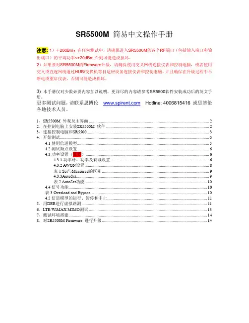
SR5500M 简易中文操作手册注意: 1)+20dBm:在任何测试中,请确保进入SR5500M的各个RF端口(包括输入端口和输出端口)的平均功率<+20dBm,否则可能造成损坏。
2)如果要对SR5500M的Firmware升级,请确保使用交叉网线连接仪表和控制电脑,或者使用交叉或直连网线通过HUB/交换机等自适应设备连接仪表和控制电脑。
并且确保在升级过程中不断电或重启仪表,否则可能造成损坏。
3) 本手册仅对少数必要内容加以说明,更详尽的内容请参考SR5500软件安装成功后的英文手册。
更多测试问题,请联系思博伦 Hotline: 4006815416 或思博伦各地技术人员。
1、SR5500M 外观及主界面 (2)2、在控制电脑上安装SR5500M 软件 (2)3、连接控制电脑和SR5500 (3)4、开始测试 (5)4.1使用信道模型 (5)4.2测试频点设置 (6)4.3功率设置(重要) (6)4.3.1功率计、功率及衰减设置 (6)4.3.2 AWGN设置 (8)表1 Set与Measured的区别 (9)4.3.3AutoSet (9)表2 AutoSet功能 (10)4.4信号功能 (10)表3 Overload and Bypass (10)4.5信道模型的运行、暂停和中止 (11)5、用DEE进行虚拟路测 (11)6、LTE/WiMAX MIMO测试 (13)7、测试环境搭建 (14)8、对SR5500M Firmware 进行升级 (14)1、SR5500M 外观及主界面2、在控制电脑上安装SR5500M 软件¾在安装SR5500M 软件之前,请启动SR5500M,从SR5500M前面的蓝色液晶屏上确认SR5500M的版本。
然后在控制电脑上安装相应版本的软件。
各版本的软件从以下网址可以免费获得:/的“Download Software Updates”链接下载SR5500M 最新的软件。
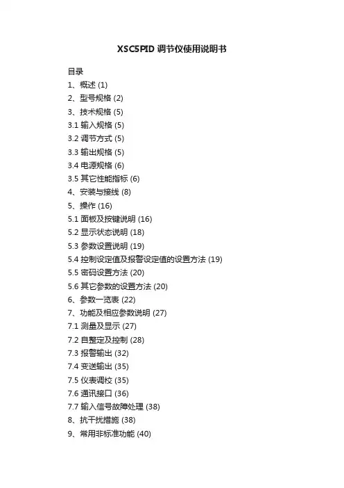
XSC5PID调节仪使用说明书目录1、概述 (1)2、型号规格 (2)3、技术规格 (5)3.1 输入规格 (5)3.2 调节方式 (5)3.3 输出规格 (5)3.4 电源规格 (6)3.5 其它性能指标 (6)4、安装与接线 (8)5、操作 (16)5.1 面板及按键说明 (16)5.2 显示状态说明 (18)5.3 参数设置说明 (19)5.4 控制设定值及报警设定值的设置方法 (19) 5.5 密码设置方法 (20)5.6 其它参数的设置方法 (20)6、参数一览表 (22)7、功能及相应参数说明 (27)7.1 测量及显示 (27)7.2 自整定及控制 (28)7.3 报警输出 (32)7.4 变送输出 (35)7.5 仪表调校 (35)7.6 通讯接口 (36)7.7 输入信号故障处理 (38)8、抗干扰措施 (38)9、常用非标准功能 (40)10、常见问题及解决办法 (41)概述1、概述XSC5系列PID智能调节仪与各类传感器、变送器配合,可实现对温度、压力、液位、成分等过程量的测量、变换、显示、通讯和控制。
采用先进的PID智能控制算法,抗超调,具备自整定(A T)功能。
误差小于0.2%F·S,并具备调校、数字滤波功能,可帮助减小传感器、变送器的误差,有效提高系统的测量、控制精度。
适用于电压、电流、热电阻、热电偶、m V、电位器、远传压力表等信号类型。
3点报警输出,可选择12种报警方式,报警灵敏度独立设定。
具备延时报警功能,有效防止干扰等原因造成误报。
全透明、高速、高效的网络化通讯接口,实现计算机与仪表间完全的数据传送和控制。
独有的控制权转移功能使计算机可以直接控制仪表的报警输出、控制输出和变送输出。
多种外形尺寸和面板形式可供选择。
良好的软件平台,具备二次开发能力,能够满足特殊的功能需求。
提供测试软件,组态软件和应用软件技术支持。
产品获得权威机构电磁兼容(EMC)检验证书。
光谱仪调试说明书1. 系统概述光谱仪是一种用于分析物质光谱特性的仪器,广泛应用于物理、化学、生物等领域。
本调试说明书将为您提供光谱仪的详细调试步骤和操作指南,以确保您能够正确使用和调试光谱仪。
2. 调试前准备在开始调试光谱仪之前,请确保您已经完成了以下准备工作:- 正确连接光谱仪和电源;- 检查仪器及其配件的完整性和清洁度;- 熟悉光谱仪的各个部件和功能。
3. 硬件调试3.1 电源设置将适配器插入光谱仪电源插口,并将电源插头插入电源插座。
请务必确认电源电压与仪器要求相符。
3.2 信号输入将待测物体的信号输入到光谱仪。
可以通过连接光纤、探头或者其他信号源的方式,将要分析的信号输入到光谱仪的输入接口。
3.3 仪器校准光谱仪需要进行校准以确保其输出的数据准确可靠。
按照仪器提供的校准指南,进行仪器的零点校准和波长校准。
4. 软件调试4.1 软件安装按照光谱仪供应商提供的软件安装步骤,将光谱仪的控制软件安装到计算机上。
确保安装过程中不出现任何错误。
4.2 仪器连接通过USB、LAN等方式将光谱仪与计算机连接。
确保连接稳定可靠,并正确安装驱动程序。
4.3 软件设置启动光谱仪控制软件,并根据软件提供的操作指南设置相关参数。
包括信号采集频率、波长范围等。
4.4 数据获取根据需要,选择合适的数据获取模式,并进行数据采集。
确保光谱仪能够准确获取待测信号的光谱特性。
5. 故障排除在调试过程中可能会遇到各种问题和故障。
下面列举一些常见问题及其解决方法:- 仪器无法开机或无法正常工作:请检查电源连接是否正确,电源是否正常;- 数据获取异常:请检查信号输入是否正确,校准是否准确;- 软件运行异常:请重启软件,并检查驱动程序是否安装正确。
6. 注意事项在使用光谱仪进行调试和操作时,请注意以下事项以确保安全和正确性:- 确保光谱仪处于稳定的工作环境中,避免强光照射和强磁场干扰;- 调试和操作时,务必按照操作手册和说明书的指引进行,避免操作错误;- 定期对光谱仪进行维护和保养,确保其可靠性和使用寿命。
bosense纠偏器说明书
1:将需要纠偏的卷筒料按要求固定在纠偏机指定位置,并按要求与切袋机或印刷机连接。
2:把纠偏机电源连接线接入三相电插板,打开纠偏机控制器电源总开关、电眼开关、检查纠偏控制器面板、电眼灯是否正常显示。
3:根据纠偏实际要求调节电眼位置、左右纠偏按钮、纠偏速度、张力大小、单双纠偏调节为单路纠偏。
4:纠偏控制器调速范围:0~10;数值越小纠偏速度越快,一般建议纠偏速度调为3。
5:张力控制器:建议调节为0.25KG。
6:左右纠偏的调节:根据纠偏实际需求;纠左边调为左;纠右边调为右。
7:注意:纠偏控制器调节任何按钮前,请先按开关按钮。
RWF50.2 和 RWF50.3比例调节仪用于比调或多段燃烧器和空调系统的温度/压力优化控制用户手册RWF50.2/RWF50.3 调节器以及本用户手册专供在其产品中使用 RWF50.2 或 RWF50.3 的原始设备制造商 (OEM) 使用!告诫!RWF50 数据表 N7866 中给出的所有安全、警告和技术信息也显示在本文件中。
CC1U7866zh Building Technologies Division2/68补充文件数据表 RWF50 ........................................................................................................ N7866 环保声明 RWF50 ..................................................................................................... E78663/684/68目录1前言 (9)1.1一般提示 (9)1.2手册说明 (10)1.2.1安全技术提示 (10)1.2.2警告符号 (10)1.2.3提示符号 (11)1.2.4显示类型 (11)1.3说明 (12)1.4程序图 (13)2识别设备规格 (14)2.1铭牌 (14)2.2供货范围 (14)3安装 (15)3.1安装地点和气候条件 (15)3.2尺寸 (15)3.3并排安装 (16)3.4在控制柜面板上开孔安装 (16)3.5从控制柜面板上拆除 (17)3.6前面板的保养 (17)4电路连接 (18)4.1安装说明 (18)4.2电隔离 (20)4.3端子配置 (21)5运行模式 (23)5.1小火运行 (23)5.2大火运行 (24)5.2.1比例调节燃烧器:三位浮点输出 (24)5.2.2燃烧器比例模拟量输出 (25)5.2.3二段燃烧器:三位浮点输出 (26)5.2.4二段燃烧器:模拟量输出 (27)5.3燃烧器停机 (28)5.4预置设定点 (29)5.5反应阈值 (q) (30)5.6设备冷启动 (31)5.7热冲击保护 (TSS) (33)6操作 (34)5/686.4手动操作比例燃烧器 (37)6.5手动操作二段燃烧器 (38)6.6启动自整定 (39)6.7显示软件版本 (40)7参数设置PArA (41)8ConF配置 (44)8.1模拟量输入端InP1 (45)8.2调节器Cntr (46)8.3热冲击保护 (TSS) rAFC (47)8.4控制输出OutP (48)8.5二进位输入binF (49)8.6显示diSP (50)9自整定功能 (51)9.1大火运行自整定 (51)9.2检查控制参数 (53)10PC 软件 ACS411 (54)10.1安全提示 (54)10.2正确的参数设置 (54)10.3更改参数 (54)10.4适用位置 (55)10.5许可证规定和责任规定 (55)10.6PC 软件 ACS411 的购买 (55)10.7语言 (55)10.8操作系统 (55)10.9硬件前提条件 (55)10.10安装 (56)10.11其他 (57)10.11.1使用 USB 接口 (57)10.11.2USB 接口供电 (57)11答疑解难 ... .. (58)11.1警告消息 (58)11.2其他 (58)12技术参数 (59)12.1输入 (59)12.1.1电阻式温度计 (59)6/6812.3控制输出OutP (60)12.4调节器 (61)12.5电气数据 (61)12.6外罩 (61)12.7环境条件 (62)12.8段式显示 (62)12.9标准与证书 (62)13图例 (63)14插图索引 (65)7/688/681 前言1.1 一般提示☞使用设备之前,请阅读本用户手册。
本文部分内容来自网络整理,本司不为其真实性负责,如有异议或侵权请及时联系,本司将立即删除!== 本文为word格式,下载后可方便编辑和修改! ==博世手电钻说明书篇一:博世电动工具10.8充电钻说明书小尺寸,大功率。
采用锂电技术的 14.4 伏和 18 伏基本机型充电式电钻/起子机不仅设计紧凑,而且性能卓越、速度高、使用时间长。
经销商团队(bss)中的翘楚,年销售额均名列前茅。
公司主营进口、国产专业电动工具、气动工具、五金手动工具、机电设备等业务,资源丰富,业务娴熟,为国内知名电动工具、机电设备供应商。
g = 专业级 ( gbh 2-22 re )p = 家用级 ( pbs 75a )第二、三位字母表示机器的种类bm = 电钻(gbm 350 re)sb = 冲击钻(gsb 13 re)bh = 电锤 (gbh 2-22 re)sh = 电镐(gsh 388 x )sr = 充电式起子机 (gsr 9.6-2)ws = 角磨机 ( gws 7-125 )st = 曲线锯 ( gst 65e )ho = 电刨(gho 10-82)hg = 热风枪(ghg 500-2)dm = 云石机(gdm 13-34)第四位后数字表示机器的主要参数公斤级别( gbh 2-22 s)功率 ( gbm 350 re )最大加工直径(gbh2-26re)几挡机械调速 ( gbm13-2 re )电压(充电工具)(gsr9.6- 1 )锯割能力 ( gst54 e )盘片直径( gws14-150ci )后缀字母这款机器所具有的功能r = 正反转 ( gsb 550 re )e = 电子无级调速 ( gsb 550 re )a = 吸尘功能 ( gss 280 a )p = 摆动功能 ( gst 85 pbe )b = 弧型手柄 ( gws24-180b )v = 电压(充电工具) ( gsr 7.2 v )c = 恒速控制 ( gws 8 – 100 ce )l = 长臂直磨机 ( ggs 27 l )s = 平钻功能 ( gbh2-24dsr )d = 凿击功能 ( gbh 5 – 38 d )f = 夹头更换( gbh4dfe )x = 六角钻/凿头 ( gbh5-38x )[2]经验丰富:五百强信赖的合作伙伴,在电动工具行业经营15年以上,对市场及产品有着独特的认识,可以为客户提供专业的产品技术咨询、产品维修保养等服务;专业团队。
刀具预调仪操作保养规程引言在机械加工过程中,正确的调整刀具位置和角度对产品的加工质量起着极为重要的作用。
随着科技的进步,越来越多的刀具预调仪应运而生,极大地简化了调整刀具的过程。
本文就刀具预调仪的操作和保养进行规程说明。
操作流程准备工作1.确认刀具预调仪型号和需要调整的刀具类型;2.清理刀具预调仪的工作平台上的灰尘和油渍。
调整刀具角度1.将需要调整的刀具装至预调仪定位架上;2.打开预调仪电源,并将刀具预调仪平台复位;3.在预调仪控制面板上选择“刀具角度调整”操作;4.在控制面板上设置正确的刀具尺寸和角度;5.调整刀具的角度,待刀具角度调整完成后,锁紧刀具定位架。
调整刀具高度1.选择“刀具高度调整”操作;2.开启升降装置,将预调仪工作平台上的刀具移动到加工台面上;3.调整刀具高度(与被加工工件位置和高度保持一致),让刀具顶头与工件。
完成工作1.关闭预调仪电源;2.将调整好的刀具卸下。
保养维护1.切勿将液体或其他物质倒入预调仪内部;2.建议定期对预调仪进行清洁、检查,并使用抗静电器进行防静电处理;3.使用预调仪前,应仔细检查顶针、螺钉、固定装置等是否松动,防止在操作过程中产生异响或破坏设备;4.防止预调仪长时间运行而导致设备过热损坏;5.不要在工作中随意拆卸和改动预调仪内部设备,以免影响设备性能和操作安全。
总结在刀具的预调过程中,刀具预调仪的使用大大提高了刀具定位的精度和效率。
经过本文的操作规程和保养维护的介绍,希望能够使读者更加深入地了解刀具预调仪的操作流程和保养维护,为加工过程中的安全和高效提供保障。
XSC5E0796×48 尺寸的仪表名 称PID 调节仪 XSC5 系列使用说明书③ 指示灯④ 设置键 72×72 尺寸的仪表 操 作 键请不要使用在原子能设备、医疗器械等与生命相关的设备上。
本仪表没有电源保险丝,请在本仪表电源供电回路中设置保险丝等安全断路器件。
请不要在本产品所提供的规格范围之外使用。
请不要使用在易燃易爆的场所。
请避免安装在发热量大的仪表(加热器、变压器、大功率电阻)的正上方。
为了您的安全,在使用前请阅读以下内容⑤ 左 键 ⑥ 确认键 ⑦ 增加键 ⑧ 减小键注意安全 说 明 OUT:模拟量输出时始终亮,位式输出 断开时灭,接通时亮 AT:自整定运行时亮 AL1:第 1 报警点状态显示 AL2:第 2 报警点状态显示 AL3:第 3 报警点状态显示 M:手动输出时亮,控制权转移到计算机后闪烁 控制状态下,按住 2 秒钟以上不松开则进入设置 状态 在设置状态下,显示参数符号时,按住 2 秒以上 不松开进入下一组参数或返回测量状态 在控制状态下,切换第二显示状态 在设置状态下:① 调出原有参数值 ② 移动修改位 在控制状态下, 进行手动/自动切换 在设置状态下,存入修改好的参数值 在手动控制输出时,增加控制输出量 在设置状态下,增加参数数值或改变设置类型 在手动控制输出时,减小控制输出量 在设置状态下,减小参数数值或改变设置类型 第四组参数 通讯及其它 符号 名称 内容 Add 仪表通讯地址 bAud 通讯速率选择 ctd 报警输出控制权选择 ctA 控制、变送输出控制权选择 oA1 第 1 组参数是否受密码控制选择 HL 设定值显示内容选择 bout 故障代用值 Li 冷端补偿修正值 boP 变送输出信号选择 bA-L 变送输出下限 bA-H 变送输出上限 注 1:该参数的值以符号形式表示,下表给出了对应关系: 序号 显示符号 输入信号 序号 显示符号 0 Pt100 11 1 cu100 12 2 cu50 13 3 BA1 14 4 BA2 15 5 G53 16 6 K 17 7 S 18 8 R 19 9 b 20 10 N 注 2: 电位器输入时,输入信号选择参数设置为 注 3: 0~10V 输入时,输入信号选择参数设置为 注 4: 0~3 顺序对应 注 5: 0~11 顺序对应 注 6: 0~3 顺序对应 注 7: 0 对应 ,1 对应 , , 注 8: 0~3 顺序对应 注 9: 0~2 顺序对应 . , 到 , 。
比博士RS5调节说明书
往H方向调节即是回弹慢往H方向调节即是下压硬。
快慢阻尼可调24段。
往S方向调节即是回弹快,往H方向调节即是回弹慢,软硬阻尼可调24段往S方向调节即是下压软往H方向调节即是下压硬。
可调的减震器有一个齿盘,拧紧后可获得不同的软硬度。
改变空气弹簧的气体压力大小用来进行调节。
调整汽车的减震需要找专业的工作人员进行精准的调整,调整的过程是非常复杂的。
比博士减震器是用来抑制弹簧吸震后反弹时的震荡及来自路面
的冲击。
广泛用于汽车,为了加速车架与车身振动的衰减,用来改善汽车的行驶平顺性。
在经过不平路面时,虽然吸震弹簧可以过滤路面的震动,但弹簧自身还会有往复运动,而减震器就是用来抑制这种弹簧跳跃的。