ISO 17636:2003中文版 焊缝的无损检验.熔焊接头的放射检验
- 格式:pdf
- 大小:694.61 KB
- 文档页数:33


国际标准ISO 176372003焊缝的无损检测——金属材料熔化焊接头的外观检验标准号ISO4137:2003(E)© ISO目录1 范围 (3)2 检测条件和设备 (3)3 人员资格 (4)4 外观检验 (4)5 检测报告 (6)焊缝的无损检测——金属材料熔化焊接头的外观检验1 范围本标准规定了金属材料熔化焊焊缝的外观检验方法。
本标准也可用于焊接之前的接头外观检验。
2 检测条件和设备表面光照度至少应达到350LX,推荐采用500LX的光照度。
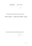
为了便于直接检查,在检查表面600mm,视角至少30°范围内,应为外观检测备好足够的空间(见图1)。
a 范围图1 检测范围当不具备图1规定的检测范围条件,或应用标准另有规定时,应考虑采用放大镜、内窥镜、纤维光导或相机做间接检查。
为了获得缺欠和背景之间良好对比和鲜明的效果,可采用辅助光源。
外观检验无法提供决定性结果时,应附加其他表面无损试验方法。
附录A给出了外观检验设备示例。
3 人员资格焊缝外观检验和最终结果评定应由具备资格和能力的人员进行。
人员资格的评定建议按ISO9712或有关工业部门相应等级的类似标准。
4 外观检验4.1 总则本国际标准不规定外观检验的范围。
外观检验范围应根据应用文件或产品标准事先规定。
检查人员应有条件获得必要的检验文件和产品文件。
所有焊前、焊接过程中或焊后的外观检验应在操作可达性条件下进行。
这可能包括含表面处理的外观检验。
4.2 坡口的外观检验要求做焊前外观检验时,应对接头做如下检查:a)焊接坡口的形状和尺寸满足焊接工艺规程的要求;b)熔化面和相邻表面是清洁的,根据应用标准或产品标准进行了所要求的表面处理;c)按照图样和工艺指令,对被焊工件进行了正确的固定。
4.3 焊接过程中的外观检验有要求时,在焊接过程应对焊缝进行如下检查:a)每条焊道或焊层被后续焊道覆盖前进行了清理,特别要注意焊缝金属和熔化面的结合处;b)无外观缺陷,比如裂纹或气孔;如果发现缺陷,应做记录以便在进一步焊接之前进行补救;c)焊道之间、焊缝与母材之间的过渡良好,便于下道焊缝熔合良好;d)为了保证能按照规定完整地去除焊缝金属,气刨的深度和形状应符合WPS要求,或与原始坡口大体一致;e)进行了所有必要的修复或补救措施之后,焊缝符合WPS的原始要求。

X射线探伤检测规程一、依据及适用范围依据ISO17636:2003、ISO10675-1:2008标准和本公司设备的特殊性制定本操作规程,本规程适用于对焊缝进行无损检测射线探伤前应做的准备工作和射线探伤中全过程的管理。
二、探伤前工艺准备1.人员要求从事射线照相检验的人员必须持有国家有关部门颁发的,并与其工作相适应的资格证书。
无损检测人员应每年检查一次身体,校正视力不得低于1.0。
2.工件表面状态要求工件焊缝及热影响区表面质量应经焊接检验员外观检查合格,表面的不规则状态在底片上的图象应不掩盖焊缝中缺陷或与之相混淆(如溅物、油污、锈蚀、凹坑、焊瘤、咬边等),否则应做适当的修整。
3.工件划线按照射线检测工艺卡在规定的检测部位划线。
采用单壁透照时需在工件两侧(射源侧和胶片侧)同时划线,并要求所划的线段尽可能对准。
采用双壁单影透照时,只需在工件胶片侧划线。
划线顺序由小号指向大号,纵焊缝按从左至右顺序,环向焊缝采用顺时针方向划线编号。
(工件表面应作出永久性标记以作为对每张底片重新定位的依据,工件不适合打印标记时,应采用详细的透照部位草图和其它的有效方法标注)。
4.像质计和标记摆放4.1像质计的摆放丝型像质计应放在射源一侧的工件表面上,位于被检焊缝的一端(被检长度的1/4处),钢丝横跨焊缝并与焊缝方向垂直,细丝置于外侧。
当射源一侧无法放置像质计时,可将其放在胶片侧,像质计应附加“F”标记以示区别,做一次对比试验,使实际像质指数达到规定要求。
外径大于等于200 mm的管子或容器环缝,采用射线中心法做周向曝光时,整圈环焊缝应等间隔放置至少三个像质计。
4.2.标记的摆放各种铅字标记应齐全,包括有:(↑)中心标记、(↑)搭接标记(↑)、工件编号、焊缝编号,部位编号,钢板厚度、焊工代号和透照日期。
返修透照时,应加返修标记R1、R2。
各种标记的摆放位置应距离焊缝边缘至少5mm,其中搭接标记的位置:在双壁单影或射源在内F>R的透照方式时,应放在胶片侧,其余透照方式应放在射源侧。

外观检验ISO17637:2003-焊缝外观检验-熔化焊接头外观检验1 范围本国际标准的覆盖范围是金属材料熔化焊外观检验。
它也可以用于接头的焊前外观检验。
2 检测条件和设备表面光照度至少应达到350LX,建议应达到500LX。
出于直接实施检查的目的,在将实施检查的表面600mm之内,应给外观检测备好足够的空间,而且其检测角度不应小于大约30°(见图1)。
a 范围图1 检测范围当不能根据图1的检测范围或有应用标准规定时,应考虑采用放大镜、内窥镜、纤维光导或相机间接检查。
可采用辅助光源获得缺陷和背景之间的良好对比和鲜明效果。
在有疑义的情况下,对表面有缺陷之处,应采用其他无损试验方法来辅助外观检测。
外观检验检测设备的举例在附录A中给出。
3 人员资格从事焊缝外观检验和最终结果评定应该是有资格和能力的人。
人员资格评定推荐按ISO9712或相关工业部门的适当水平的同等标准。
4 外观检验4.1 总则本国际标准没有定义外观检验的范围。
然而,这些必须事先定义,比如参考某应用或产品标准。
检查者应可接近进行检测和查找产品文件。
焊前、焊接过程中或焊后的所有外观检验必须在物理可接近的情况下进行。
这可能包含表面处理的外观检验。
4.2 接头外观检验准备如果焊前需要外观检验,应检验接头以确定:a)焊接接头坡口准备的外形和尺寸达到焊接工艺规程的要求;b)熔化面和相邻表面是清洁的,且已进行了所有根据应用或产品标准的表面处理;c)将被焊的部分根据划线或说明互相对正正确。
4.3 焊接过程中的外观检验如果需要的话,须检测焊接过程以确定:a)每条焊道或层应在被覆盖前进行清理,特别要注意焊缝金属和熔化面的结合处;b)没有外观缺陷,比如裂纹或孔;如果发现缺陷,应提出来以便在进一步焊接之前进行补救;c)焊道之间、焊缝与母材之间的过渡成型良好,以便下一道完成良好;d)刨削的深度和外形是根据WPS的或与原始凹槽外形比较以确定焊缝金属按规定的完全去除;e)在所有必要的修补或补救措施之后,焊缝符合WPS的原始要求。

射线检测工艺标准1.适用范围本工艺标准适用于锅炉、压力容器、压力管道特种设备熔化焊对接接头的射线检测和质量级。
本工艺标准为锅炉、压力容器、压力管道特种设备通用的射线检测工艺标准,它与施工图纸和相关标准、规范配合使用。
2.编制依据2.1 本工艺标准主要依据JB4730编制,锅炉、压力容器、压力管道检测中若需执行行业标准时,应以现行行业标准为准。
2.2 本工艺标准执行时若与国家,行业标准相抵触时,应以现行行业标准为准。
3.射线检测范围及要求3.1 射线检测范围3.1.1 锅炉、压力容器、压力管道对接接头检测的数量抽查比例,应与施工图纸和相应标准、规范的要求相一致。
3.1.2 焊接接头进行抽查检测时,若发现有不合格的缺陷,应做抽查数量双倍数目的补充检测抽查,双倍补充检测仍有不合格,则应对焊工焊接的全部焊接接头进行无损检测。
3.2 射线检测要求3.2.1 焊接接头的射线检测,应执行G B3323《钢熔化焊对接接头射线照相和质量分级》的规定,射线照相的质量要求不应低于AB级。
3.2.2 焊接接头质量的评定,应根据锅炉、压力容器、压力管道检测行业标准要求执行的相关标准满足施工图纸的要求。
4.检测人员4.1 从事射线检测人员,必须持有锅炉、压力容器无损检测人员资格证书。
评片人员必须具备II级或II级以上的资格,操作人员必须具备I级或I级以上的检测资格。
4.2 评片人员的视力应符合JB4730标准4.3.3条的规定。
5.检测时机5.1 射线检测前,焊缝及热影响区的表面质量应经外观检查合格。
表面的不规则状态在底片上的影象应不掩盖焊缝中的缺陷或与之混淆,否则表面应经修整合格后方可进行检测。
5.2 具有延迟裂纹倾向材质的焊缝,射线检测应在焊后24小时后方可进行。
6.设备、胶片、增感屏6.1 射线机、观片机、黑度计等射线检测设备,应经调试合格并符合有关标准规定。
6.2 射线检测应使用中粒、中速工业用胶片和铅箔增感屏。
7.象质计7.1 射线检测用象质计必须符合JB4730的要求。

国际标准ISO17637:2003焊缝无损检测—熔化焊焊接接头外观检测1 范围本国际标准的适用范围是金属材料熔化焊外观检测,它也可以用于接头的焊前外观检测。
2 检测条件和设备表面光照度至少应达到350Lx,建议应达到500Lx。
出于直接实施检测的目的,在距实施检测的表面600mm之内,应给外观检测备好足够的空间,且其检测角度不应小于大约30°(见图1)。
a 范围图1 检测状态当不能满足图1的检测状态或相关应用标准规定时,应考虑采用放大镜、内窥镜、纤维光导或相机间接检测。
可通过采用辅助光源,来获得缺陷和背景之间的良好对比和鲜明效果。
在有疑义的情况下,对表面有缺陷之处,应采用其他无损试验方法来辅助外观检测。
外观检测设备的举例在附录A中给出。
3 人员资格从事焊缝外观检测和最终结果评定的应该是有资格和能力的人员。
人员资格评定推荐按ISO9712或相关工业部门的适当水平的同等标准。
4 外观检测4.1 总则本国际标准没有定义外观检测的范围。
然而,这些必须事先定义,比如参考某应用或产品标准。
检测人员应查看进行检测和生产的产品文件。
焊前、焊接过程中或焊后的所有外观检测,必须在物理可接近的情况下进行。
这可能包含表面处理后的外观检测。
4.2 接头准备的外观检测如果焊前需要进行外观检测,应检测接头以确定以下内容:a)焊接接头坡口准备的外形和尺寸达到焊接工艺规程的要求;b)熔化面和相邻表面干净,且已进行了所有根据应用或产品标准的表面处理;c)将被焊的部分根据图纸或规程互相对位正确。
4.3 焊接过程中的外观检测如果需要的话,须检测焊接过程以确定以下内容:a)每条焊道或层应在被覆盖前进行清理,特别要注意焊缝金属和熔化面的结合处;b)没有外观缺陷,比如裂纹或孔穴;如果发现缺陷,应提出来以便在下一步焊接之前进行补救;c)焊道之间、焊缝与母材之间的过渡成型良好,以便下一道完成良好;d)刨削的深度和外形是根据WPS或与原来沟槽形状来比较,以确定焊缝金属可按规定完全去除;e)在所有必要的修补或补救措施之后,焊缝应符合WPS的原来要求。


焊缝的无损试验——熔焊接点的放射检验目录1.范围 (2)2.标准的参考文献 (3)3.术语和定义 (3)3.1额定厚度t (3)3.2穿透深度w (3)3.3 物体到胶片的距离b (3)3.4射线源大小d (4)3.5 射线源到胶片的距离SFD (4)3.6射线源到物体的距离f (4)3.7直径De (4)4符号和缩写 (4)5.放射技术的等级 (5)6概述 (5)6.1致电离射线辐射的防护 (5)6.2表面准备和生产步骤 (5)6.3在放射照片中焊缝的位置 (5)6.4 放射的标识 (6)6.5标注 (6)6.6胶片的重叠 (6)6.7图像质量指数的类型和位置 (6)6.8图像质量的评估 (7)6.9最低图像质量值 (7)6.10人员资格 (7)7进行辐射摄影建议的技术 (8)7.1检验调节 (8)7.2电压和辐射源的选择 (12)7.3胶片体系和屏幕 (13)7.4光束的调准 (15)7.5扩散辐射的减少 (16)7.6辐射源至物体的距离 (16)7.7一个单独照射的最大区域 (17)7.8辐射摄影术的色度 (17)7.9处理 (18)7.10胶片观测条件 (18)8试验报告 (18)附录A(规范化的) (20)铁材料的最低图像质量值 (20)A.1单面墙技术,IQI在辐射源边 (20)附录B(介绍性的) (27)圆形对接焊合格试验的参考曝光数量 (27)参考文献 (27)1.范围本国际标准规定了金属材料熔焊接点放射检验的基本技术。
采用最经济的方法来获得满意效果和可以复验的结果。
该技术是基于普遍认可的实践和基础性理论基础上的。
此国际标准适用于板或管上的熔焊接点的试验。
它是根据ISO5579上的基本条款的。
此国际标准没有规定读数的验收等级。
2.标准的参考文献下列参考文献是本标准应用不可缺少的部分,对于有日期的参考,只有标注日期的版本有效,对于没有标注日期的参考,采用最新的版本(包括任何的修订本)。

EUROPEAN STANDARD NORME EUROPÉENNE EUROPÄISCHE NORM EN ISO 17638 November 2016ICS 25.160.40 Supersedes EN ISO 17638:2009English VersionNon-destructive testing of welds - Magnetic particletesting (ISO 17638:2016)Contrôle non destructif des assemblages soudés - Magnétoscopie (ISO 17638:2016) Zerstörungsfreie Prüfung von Schweißverbindungen - Magnetpulverprüfung (ISO 17638:2016)This European Standard was approved by CEN on 2 October 2016.CEN members are bound to comply with the CEN/CENELEC Internal Regulations which stipulate the conditions for giving this European Standard the status of a national standard without any alteration. Up-to-date lists and bibliographical references concerning such national standards may be obtained on application to the CEN-CENELEC Management Centre or to any CEN member.This European Standard exists in three official versions (English, French, German). A version in any other language made by translation under the responsibility of a CEN member into its own language and notified to the CEN-CENELEC Management Centre has the same status as the official versions.CEN members are the national standards bodies of Austria, Belgium, Bulgaria, Croatia, Cyprus, Czech Republic, Denmark, Estonia, Finland, Former Yugoslav Republic of Macedonia, France, Germany, Greece, Hungary, Iceland, Ireland, Italy, Latvia, Lithuania, Luxembourg, Malta, Netherlands, Norway, Poland, Portugal, Romania, Slovakia, Slovenia, Spain, Sweden, Switzerland, Turkey and United Kingdom.EUROPEAN COMMITTEE FOR STANDARDIZATIONC O M I TÉE UR O PÉE N DE N O R M A L I SA T I O NE UR O PÄI SC HE S KO M I T E E FÜR N O R M UN GCEN-CENELEC Management Centre: Avenue Marnix 17, B-1000 Brussels© 2016 CEN All rights of exploitation in any form and by any means reservedworldwide for CEN national Members.Ref. No. EN ISO 17638:2016 EBS EN ISO 17638:2016EN ISO 17638:2016 (E) 3European forewordThis document (EN ISO 17638:2016) has been prepared by Technical Committee ISO/TC 44 “Welding and allied processes” in collaboration with Technical Committee CEN/TC 121 “Welding and allied processes” the secretariat of which is held by DIN. This European Standard shall be given the status of a national standard, either by publication of an identical text or by endorsement, at the latest by May 2017, and conflicting national standards shall be withdrawn at the latest by May 2017. Attention is drawn to the possibility that some of the elements of this document may be the subject of patent rights. CEN [and/or CENELEC] shall not be held responsible for identifying any or all such patent rights. This document supersedes EN ISO 17638:2009. According to the CEN-CENELEC Internal Regulations, the national standards organizations of the following countries are bound to implement this European Standard: Austria, Belgium, Bulgaria, Croatia, Cyprus, Czech Republic, Denmark, Estonia, Finland, Former Yugoslav Republic of Macedonia, France, Germany, Greece, Hungary, Iceland, Ireland, Italy, Latvia, Lithuania, Luxembourg, Malta, Netherlands, Norway, Poland, Portugal, Romania, Slovakia, Slovenia, Spain, Sweden, Switzerland, Turkey and the United Kingdom. Endorsement noticeThe text of ISO 17638:2016 has been approved by CEN as EN ISO 17638:2016 without any modification.BS EN ISO 17638:2016ISO 17638:2016(E) Contents PageForeword (iv)1 Scope (1)2 Normative references (1)3 Terms and definitions (1)4 Safety precautions (1)5 General (1)5.1 Information required prior to testing (1)5.2 Additional pre-test information (2)5.3 Personnel qualification (2)5.4 Surface conditions and preparation (2)5.5 Magnetizing (2)5.5.1 Magnetizing equipment (2)5.5.2 Verification of magnetization (3)5.6 Application techniques (3)5.6.1 Field directions and testing area (3)5.6.2 Typical magnetic testing techniques (6)5.7 Detection media (9)5.7.1 General (9)5.7.2 Verification of detection media performance (9)5.8 Viewing conditions (10)5.9 Application of detection media (10)5.10 Overall performance test (10)5.11 False indications (10)5.12 Recording of indications (10)5.13 Demagnetization (11)5.14 Test report (11)Annex A (informative) Variables affecting the sensitivity of magnetic particle testing (13)Bibliography (15)© ISO 2016 – All rights reserved iiiBS EN ISO 17638:2016ISO 17638:2016(E)ForewordISO (the International Organization for Standardization) is a worldwide federation of national standards bodies (ISO member bodies). The work of preparing International Standards is normally carried out through ISO technical committees. Each member body interested in a subject for which a technical committee has been established has the right to be represented on that committee. International organizations, governmental and non-governmental, in liaison with ISO, also take part in the work. ISO collaborates closely with the International Electrotechnical Commission (IEC) on all matters of electrotechnical standardization.The procedures used to develop this document and those intended for its further maintenance are described in the ISO/IEC Directives, Part 1. In particular the different approval criteria needed for the different types of ISO documents should be noted. This document was drafted in accordance with the editorial rules of the ISO/IEC Directives, Part 2 (see /directives). Attention is drawn to the possibility that some of the elements of this document may be the subject of patent rights. ISO shall not be held responsible for identifying any or all such patent rights. Details of any patent rights identified during the development of the document will be in the Introduction and/or on the ISO list of patent declarations received (see /patents).Any trade name used in this document is information given for the convenience of users and does not constitute an endorsement.For an explanation on the meaning of ISO specific terms and expressions related to conformity assessment, as well as information about ISO’s adherence to the World Trade Organization (WTO) principles in the Technical Barriers to Trade (TBT) see the following URL: /iso/foreword.html. The committee responsible for this document is ISO/TC 44, Welding and allied processes, Subcommittee 5, Testing and inspection of welds.This second edition cancels and replaces the first edition (ISO 17638:2003), which has been technically revised.Requests for official interpretations of any aspect of this document should be directed to the Secretariat of ISO/TC 44/SC 5 via your national standards body. A complete listing of these bodies can be found at .© ISO 2016 – All rights reservedBS EN ISO 17638:2016 INTERNATIONAL STANDARD ISO 17638:2016(E)Non-destructive testing of welds — Magnetic particle testing1 ScopeThis document specifies techniques for detection of surface imperfections in welds in ferromagnetic materials, including the heat affected zones, by means of magnetic particle testing. The techniques are suitable for most welding processes and joint configurations. Variations in the basic techniques that will provide a higher or lower test sensitivity are described in Annex A.This document does not specify acceptance levels of the indications. Further information on acceptance levels for indications may be found in ISO 23278 or in product or application standards.2 Normative referencesThe following documents are referred to in the text in such a way that some or all of their content constitutes requirements of this document. For dated references, only the edition cited applies. For undated references, the latest edition of the referenced document (including any amendments) applies. ISO 3059, Non-destructive testing — Penetrant testing and magnetic particle testing — Viewing conditions ISO 9934-1:2015, Non-destructive testing — Magnetic particle testing — Part 1: General principles ISO 9934-2, Non-destructive testing — Magnetic particle testing — Part 2: Detection media ISO 9934-3, Non-destructive testing — Magnetic particle testing — Part 3: Equipment3 Terms and definitionsFor the purposes of this document, the terms and definitions given in ISO 12707 and ISO 17635 apply. ISO and IEC maintain terminological databases for use in standardization at the following addresses:— IEC Electropedia: available at /— ISO Online browsing platform: available at /obp4 Safety precautionsSpecial consideration shall be given to toxic, inflammable and/or volatile materials, electrical safety and unfiltered UV radiation.Magnetic particle testing often creates high magnetic fields close to the object under test and the magnetising equipment. Items sensitive to these fields should be excluded from such areas.5 General5.1 Information required prior to testingPrior to testing, the following items shall be specified (where applicable):a)specific test procedure;b)certification requirements for NDT personnel;© ISO 2016 – All rights reserved 1BS EN ISO 17638:2016ISO 17638:2016(E)extent of coverage;state of manufacture;testing techniques to be used;overall performance test;any demagnetization;acceptance level;action necessary for unacceptable indications.5.2 Additional pre-test informationPrior to testing, the following additional information can also be required:type and designation of the parent and weld materials;welding process;location and extent of welds to be tested;joint preparation and dimensions;location and extent of any repairs;post-weld treatment (if any);surface conditions.Operators may ask for further information that could be helpful in determining the nature of any indications detected.5.3 Personnel qualificationMagnetic particle testing of welds and the evaluation of results for final acceptance shall be performed by qualified and capable personnel. It is recommended that personnel be qualified in accordance with ISO 9712 or an equivalent standard at an appropriate level in the relevant industry sector.5.4 Surface conditions and preparationAreas to be tested shall be dry unless appropriate products for wet surfaces are used. It may be necessary to improve the surface condition, e.g. by use of abrasive paper or local grinding to permit accurate interpretation of indications.Any cleaning or surface preparation shall not be detrimental to the material, the surface finish or the magnetic testing media. Detection media shall be used within the temperature range limitations set by the manufacturer.5.5 Magnetizing5.5.1 Magnetizing equipmentGeneral magnetization requirements shall be in accordance with ISO 9934-1:2015, Clause 8. Unless otherwise specified, for example, in an application standard, the following types of alternating current-magnetizing equipment shall be used: electromagnetic yokes;© ISO 2016 – All rights reservedBS EN ISO 17638:2016ISO 17638:2016(E)b)current flow equipment with prods;c)adjacent or threading conductors or coil techniques.DC electromagnets and permanent magnets may only be used by agreement at the time of enquiry and order.The magnetizing equipment shall conform to ISO 9934-3.Where prods are used, precautions shall be taken to minimize overheating, burning or arcing at the contact tips. Removal of arc burns shall be carried out where necessary. The affected area shall be tested by a suitable method to ensure the integrity of the surface.5.5.2 Verification of magnetizationFor the verification of magnetization, see ISO 9934-1:2015, 8.2.For structural steels in welds, a tangential field between 2 kA/m to 6 kA/m (r.m.s.) is recommended. The adequacy of the surface flux density shall be established by one or more of the following methods: a)by testing a representative component containing fine natural or artificial discontinuities in the least favourable locations;b)measurement of the tangential field strength as close as possible to the surface using a Hall effect probe; the appropriate tangential field strength can be difficult to measure close to abrupt changes in the shape of a component or where flux leaves the surface of a component;c)calculation of the approximate current value in order to achieve the recommended tangential field strength; the calculation can be based on the current values specified in Figure 5 and Figure 6;d)by the use of other methods based on established principles.Flux indicators (i.e. shim-type) placed in contact with the surface under test provide a guide to the magnitude and direction of the tangential field strength, but should not be used to verify that the tangential field strength is acceptable.NOTE Information on b) is given in ISO 9934-3.5.6 Application techniques5.6.1 Field directions and testing areaThe detectability of an imperfection depends on the angle of its major axis with respect to the direction of the magnetic field. This is explained for one direction of magnetization in Figure 1.© ISO 2016 – All rights reserved 3BS EN ISO 17638:2016ISO 17638:2016(E)Keymagnetic field direction αangle between the magnetic field and the direction of the imperfection optimum sensitivity αmin minimum angle for imperfection detection reducing sensitivity αi example of imperfection orientationinsufficient sensitivity Figure 1 — Directions of detectable imperfectionsTo ensure detection of imperfections in all orientations, the welds shall be magnetized in two directions approximately perpendicular to each other with a maximum deviation of 30°. This can be achieved using one or more magnetization methods.Testing in only one field direction is not recommended but may be carried out if specified, for example, in an application standard.When using yokes or prods, there will be an area of the component in the vicinity of each pole piece or tip that will be impossible to test due to excessive magnetic field strength. This is usually seen as furring of particles.Care shall be taken to ensure adequate overlap of the testing areas as shown in Figure 2 and Figure 3.© ISO 2016 – All rights reservedBS EN ISO 17638:2016ISO 17638:2016(E)Dimensions in millimetresKeyd separation between the poles (yoke/prod )Figure 2 — Examples of effective testing area (shaded) for magnetizing with yokes and prods © ISO 2016 – All rights reserved 5BS EN ISO 17638:2016ISO 17638:2016(E)Keyeffective area overlap Figure 3 — Overlap of effective areas5.6.2 Typical magnetic testing techniquesMagnetic particle testing techniques for common weld joint configurations are shown in Figure 4, Figure 5 and Figure 6. Values are given for guidance purposes only. Where possible, the same directions of magnetization and field overlaps should be used for other weld geometries to be tested. The width of the flux current (in case of flux current technique) or of the magnetic flow (in case of magnetic flow technique) path in the material, d , shall be greater than or equal to the width of the weld and the heat affected zone +50 mm and in all cases, the weld and the heat affected zone shall be included in the effective area. The direction of magnetization with respect to the orientation of the weld shall be specified.© ISO 2016 – All rights reservedBS EN ISO 17638:2016 ISO 17638:2016(E)Dimensions in millimetresd ≥ 75b ≤ d/2β ≈ 90ºd1 ≥ 75b1 ≤ d1/2b2 ≤ d2 – 50d2≥ 75d1 ≥ 75d2 ≥ 75b1 ≤ d1/2b2 ≤ d2 − 50d1 ≥ 75d2 > 75b1 ≤ d1/2b2 ≤ d2 − 50Key1longitudinal cracks2transverse cracksFigure 4 — Typical magnetizing techniques for yokes© ISO 2016 – All rights reserved 7BS EN ISO 17638:2016 ISO 17638:2016(E)Dimensions in millimetresd ≥ 75b ≤ d/2β ≈ 90ºd ≥ 75b ≤ d/2d ≥ 75b ≤ d/2d ≥ 75b ≤ d/2Figure 5 — Typical magnetizing techniques for prods, using a magnetizing current prod spacing© ISO 2016 – All rights reservedBS EN ISO 17638:2016ISO 17638:2016(E)Dimensions in millimetres20 ≤ a ≤ 50 N ·I ≥ 8D 20 ≤ a ≤ 50 N ·I ≥ 8D20 ≤ a ≤ 50 N ·I ≥ 8DKeyN number of turns I current (r.m.s)a distance between weld and coil or cableFigure 6 — Typical magnetizing techniques for flexible cables or coils (for longitudinal cracks)5.7 Detection media5.7.1 GeneralDetection media may be either in dry powder form or magnetic inks in accordance with ISO 9934-2.5.7.2Verification of detection media performanceThe detection media used shall fulfil the requirements of ISO 9934-2.© ISO 2016 – All rights reserved9BS EN ISO 17638:2016ISO 17638:2016(E)Indications obtained with the medium to be verified shall be compared against those obtained from a medium having a known and acceptable performance. For this purpose, the reference indications may be real imperfections,photograph(s), andreplica(s).5.8 Viewing conditionsThe viewing conditions shall be in accordance with ISO 3059.5.9 Application of detection mediaAfter the object has been prepared for testing, the detection medium shall be applied by spraying, flooding or dusting immediately prior to and during the magnetization. Following this, time shall be allowed for indications to form before removal of the magnetic field.When magnetic suspensions are used, the magnetic field shall be maintained within the object until the majority of the suspension carrier liquid has drained away from the test surface. This will prevent any indications being washed away.Depending on the material being tested, its surface condition and magnetic permeability, indications will normally remain on the surface even after removal of the magnetic field due to residual magnetism within the part (mainly at the location of the poles). However, the presence of residual magnetism shall not be presumed and post evaluation techniques after removal of the prime magnetic field source are only permitted when a component has been proven by an overall performance test to retain magnetic indications.5.10 Overall performance testWhen specified, an overall performance test of the system sensitivity for each procedure shall be carried out on site. The performance test shall be designed to ensure a proper functioning of the entire chain of parameters including the equipment, the magnetic field strength and direction, surface characteristics, detection media and illumination.The most reliable test is to use representative test pieces containing real imperfections of known type, location, size and size-distribution. Where these are not available, fabricated test pieces with artificial imperfections or flux shunting indicators of the cross or disc or shim-type may be used.The test pieces shall be demagnetized and free from indications resulting from previous tests.NOTE It can be necessary to perform an overall performance test of the system sensitivity for each specific procedure on site.5.11 False indicationsFalse indications which may mask relevant indications can arise for many reasons, such as changes in magnetic permeability, very important geometry variation in, for example, the heat affected zone. Where masking is suspected, the test surface shall be dressed or alternative test methods should be used.5.12 Recording of indicationsIndications can be recorded in one or more of the following ways by using: description in writing;sketches;10 © ISO 2016 – All rights reservedBS EN ISO 17638:2016ISO 17638:2016(E)c)photography;d)transparent adhesive tape;e)transparent varnish for “freezing” the indication on the surface tested;f)peelable contrast coating;g)video recording;h)magnetic particle dispersion in an epoxy curable resin;i)magnetic tapes;j)electronic scanning.5.13 DemagnetizationAfter testing welds with alternating current, residual magnetization will normally be low and there will generally be no need for demagnetization of the object under test.If demagnetization is required, it shall be carried out using a defined method and to a predefined level. For metal cutting processes, a typical residual field strength value of H < 0,4 kA/m is recommended.5.14 Test reportA test report shall be prepared.The report should contain at least the following:a)name of the company carrying out the test;b)the object tested;c)date of testing;d)parent and weld materials;e)any post weld heat treatment;f)type of joint;g)material thickness;h)welding process(es);i)temperature of the test object and the detection media (when using media in circulation) throughout testing duration;j)identity of the test procedure and description of the parameters used, including the following:— type of magnetization;— type of current;— detection media;— viewing conditions;k)details and results of the overall performance test, where applicable;l)acceptance levels;© ISO 2016 – All rights reserved 11BS EN ISO 17638:2016ISO 17638:2016(E)m)description and location of all recordable indications;test results with reference to acceptance levels;names, relevant qualification and signatures of personnel who carried out the test.12 © ISO 2016 – All rights reservedBS EN ISO 17638:2016ISO 17638:2016(E)Annex A(informative)Variables affecting the sensitivity of magnetic particle testingA.1 Surface conditions and preparationThe maximum test sensitivity that can be achieved by any magnetic testing method is dependent on many variables but can be seriously affected by the surface roughness of the object and any irregularities present. In some cases, it can be necessary to— dress undercut and surface irregularities by grinding, and— remove or reduce the weld reinforcement.Surfaces covered with a thin non-ferromagnetic coatings up to 50 µm thickness may be tested provided the colour is contrasting with the colour of the detection medium used. Above this thickness, the sensitivity of the method decreases and may be demonstrated to be sufficiently sensitive before proceeding with the test.A.2 Magnetizing equipment characteristicsThe use of alternating current gives the best sensitivity for detecting surface imperfections. Yokes produce an adequate magnetic field in simple butt-welds but where the flux is reduced by gaps or the path is excessive through the object, as in T-joints a reduction of sensitivity can occur.For complex joint configurations, i.e. branch connections with an inclined angle of less than 90°, testing using yokes might be inadequate. Prods or cable wrapping with current flow will, in these cases, prove more suitable.A.3 Magnetic field strength and permeabilityThe field strength required to produce an indication strong enough to be detected during magnetic particle testing is dependent mainly on the magnetic permeability of the object. Generally, magnetic permeability is high in softer magnetic materials, for example, low alloy steels and low in harder magnetic materials, i.e. martensitic steels. Because permeability is a function of the magnetizing current, low permeability materials usually require application of a higher magnetization value than do softer alloys to produce the same flux density. It is essential, therefore, to establish that flux density values are adequate before beginning the magnetic particle testing.A.4 Detection mediaMagnetic particle suspensions will usually give a higher sensitivity for detecting surface imperfections than dry powders.Fluorescent magnetic detection media usually give a higher test sensitivity than colour contrast media, because of the higher contrast between the darkened background and the fluorescent indication. The sensitivity of the fluorescent method will, nevertheless, decrease in proportion to any increase in the roughness of the surface to which magnetic particles adhere and can cause a disturbing background fluorescence.© ISO 2016 – All rights reserved 13BS EN ISO 17638:2016ISO 17638:2016(E)Where the background illumination cannot be adequately lowered or where background fluorescence is disturbing, coloured detection media in conjunction with the smoothing effect of a contrast aid will usually give better sensitivity.14 © ISO 2016 – All rights reservedBS EN ISO 17638:2016ISO 17638:2016(E)Bibliography[1] ISO 9712, Non-destructive testing — Qualification and certification of NDT personnel[2] ISO 12707, Non-destructive testing — Magnetic particle testing — Vocabulary[3] ISO 17635, Non-destructive testing of welds — General rules for metallic materials[4] ISO 23278, Non-destructive testing of welds — Magnetic particle testing — Acceptance levels © ISO 2016 – All rights reserved 15This page deliberately left blank。

结构可靠性评价及失效分析第15讲焊接缺陷评定1、ISO17635:2003(EN12062:2002)《焊缝无损检测——金属材料熔化焊总则》摘要介绍1.1 应用范围本标准基于质量要求,对有关材料、焊接厚度、焊接程序和检查内容,出于质量管理的目,本标准对焊接的无损检查方法的结果的评估均做出了指导。
本标准对不同的检查形式要应用的总的规则和标准也指出了规定。
1.2 适用材料本标准适用于下列材料和其合金及其组合材料的熔化焊焊缝:——钢铁;——铝;——铜;——镍;——钛。
其他金属材料使用此标准应在合同双方之间达成协议。
1.3 检测方法的选择在表1中列出了有关表面缺陷进行焊缝检测的一般可接受的方法,在表2中列出了有关内部缺陷进行焊缝检测的一般可接受的方法。
1.4 推荐的规则和标准在标准附录A中列出了ISO5817或ISO10042质量标准和检查技术之间的校正关系,列出了检测水准和无损检测标准的可接受水准之间的质量标准关系,详见表3~表8。
表3 目视检测(VT)表4 渗透检测(PT)表5 磁粉检测(MT)表6 涡流检测(ET)表8 铁素体超声波检测(UT)2、ISO5817:2003《钢、镍、钛及其合金的熔化焊接头(高能束焊接头除外)——缺欠质量分级》摘要介绍2.1 应用范围该国际标准作为0.5mm以上钢、镍、钛及它们的合金焊缝评定等级的标准。
本标准适用于:—非合金钢和合金钢;—镍和镍合金;—钛和钛合金;—手工焊、机械焊接和自动焊接;—所有的焊接位置;—所有焊接接头,例如:对接、角接和支管连接;—下面所讲的与国际标准ISO4063编号一致的焊接方法:11 无气体保护的金属电弧焊;12 埋弧焊;13 金属气体保护焊;14 钨极气体保护焊;15 等离子焊;31 氧焰气焊(仅针对钢)。
2.2 缩写下列缩写在表1(见表9)中使用:A——气体夹杂的面积;a——角焊缝的标称厚度(参见ISO 2553);b——焊缝余高的宽度;d——气孔的直径;h——缺欠的高度或宽度;l——缺欠的长度;lp——投影面积或横截面面积;s——标称对接焊缝厚度(参见ISO 2553);t——管壁厚度或板厚(标称尺寸);Wp——焊缝宽度或断口面积的宽度或长度;z——角焊缝的焊脚长度(参见ISO 2553);α——焊趾的角度;β——角的角度误差。

焊缝检测的国内外标准对比分析,总结的真好1. 概述对于日常工件的无损检测而言,标准是最重要的工作依据。
从工件的检测方法选择、检测过程的注意事项,到工件的最终评定、报告的参数出具,往往都需要遵循一定的、供需双方均认可的标准规范。
随着国际合作的不断加强,我们和国外的交流也日益广泛。
其中,涉及到产品质量验收时,应该遵循何种标准、采取怎样的验收级别,这往往是供需双方讨论的焦点之一。
因此,将国内焊接构件焊缝无损检测标准和国外、国际标准进行一定的对比,分析其在日常生活中的应用,对于我们的工作,也是非常有好处的。
2. 国内、外焊缝无损检测标准钢结构焊缝的无损检测在国内已有成熟标准,以锅炉压力容器部门运用最为广泛,如GB/T11345,NB/T47013、GB/T3323和TB/T1558等。
近来铝合金轻量化材料的使用,使铝合金焊接结构的探伤检验也变得越来越重要,由于国内起步较晚,实用标准还不是很多。
随着航空航天和高铁技术的发展,铝合金焊接结构件越来越多。
如高速动车组全部采用铝合金车体,大量使用预制型材、板材以焊接方式连接,如法国阿尔斯通的全铝焊接车体,德国克诺尔的铝合金焊接风缸等,由于国内尚无成熟检验标准,不得不按外方要求采用国际标准进行检验,因此关于铝合金焊接结构件的无损检测标准的研究正在开展之中。
国内外关于焊接结构件的无损检测主要有下列所示标准:o GB/T 14693 焊缝无损检测符号o GB/T 3323金属熔化焊焊接接头射线照相o GB/T 12605钢管环缝熔化焊对接接头射线透照工艺和质量分级o GB/T 11345钢焊缝手工超声波探伤方法和探伤结果的分级o GB/T 15830钢制管道对接环焊缝超声波探伤方法和检验结果的分级o JB/T 9212常压钢质油罐焊缝超声波探伤o JB/T 6061焊缝磁粉检验方法和缺陷磁痕的分级o JB/T 6062焊缝渗透检验方法和缺陷磁痕的分级o NB/T 47013承压设备无损检测o TB/T 1558对接焊缝超声波探伤o ISO 5817焊缝钢、镍、钛及各自合金熔化焊接头(除波束焊外)不完整性质量分级o ISO 10042焊缝铝及其合金弧焊接头不完整性质量分级o ISO 17636-1焊缝无损检测射线检测 X和伽马射线胶片技术o ISO 17636-2焊缝无损检测射线检测 X和伽马射线电子成像技术o ISO 10675-1焊缝的无损检测第1部分钢、镍、钛及其合金制品射线检测的评价可接受水平o ISO 10675-2焊缝的无损检测第2部分铝合金制品射线检测的评价可接受水平o ISO 17640焊缝无损检测超声波检测检测技术、验收等级和结果评估o ISO 11666焊缝无损检测焊接接头超声波检测验收等级o ISO 17638焊接无损检测焊接接头磁粉检测o ISO 23278焊缝的无损检测焊接接头磁粉检测验收等级o ISO 3452无损检测渗透检测o ISO 23277焊缝无损检测焊缝渗透检测验收等级o JIS Z3105铝焊缝的射线照相检验方法和底片评级方法o JIS Z3080铝焊缝超声波斜角探伤方法及检验结果的等级分类方法o JIS Z3081铝管焊缝超声波斜角探伤方法及检验结果的等级分类方法o ASTM E1032焊接件的射线透照检测方法o ASTM E390钢熔化焊射线检验标准底片o ASTM E1648用于铝熔焊检验的射线照相参考底片3.国内、外焊缝检验标准对比分析由于ASTM标准中关于焊缝检验需要采用相应的图谱进行比对,这种方式对于要求较高的焊缝而言,相对难以评判,因此国内若无特殊需求一般很少采用。
ISO国际标准化组织ISO 17636:2003焊缝的无损检测 —— 熔化焊接头的射线检测Non-destructive testing of welds —— Radiographic testing of fusion-welded joints(翻译稿)国际标准化组织 发布ww .b z f xw .c o m国际标准化组织标准焊缝的无损检测 —— 熔化焊接头的射线检测翻译单位:哈尔滨焊接研究所 翻 译:陈宇校 对:朴东光 编 辑:朴东光2006年8月ww .b zf xw .c o1 范围本国际标准规定了金属材料熔化焊接头射线检验的基本方法。
目标是通过经济的方法得到满意的和可重复的结果。
该方法总体基于该学科中认可的实践和基本原理。
本国际标准适用于板或管的熔化焊接头检验。
它遵循ISO5579中给出的规则。
本国际标准没有规定缺陷的验收等级。
注:由于本国际标准的目的,术语“管”适用于“导管”、“管”、“水管”、“锅炉”和“压力导管”。
2 规范性引用文件下列文件对于本标准的应用是不可或缺的。
对于注日期的引用文件,只能引用指定的版本。
对于未注日期的引用文件,应采用其最新版本(包含所有修改版)。
ISO2504 焊缝射线检验和胶片观察条件——推荐模式的图象质量指示器的使用 ISO5580 无损检测——工业射线照明——最低要求ISO11699-1 无损检测——工业射线胶片——第一部分:工业射线照相系统分级ISO11699-2 无损检测——工业射线胶片——第二部分:照相过程控制,通过参考值的方法3 术语和定义由于本文件的目的,使用以下术语和定义。
3.1 公称壁厚 t指母材的公称厚度。
注:制造偏差不予考虑。
3.2 透照厚度 w射线入射方向上的材料厚度,基于公称壁厚来计算。
注:多壁透照时的透照厚度由公称壁厚计算取得。
3.3工件—胶片的距离 b在射线中心束方向上被检工件的非射线照射一侧至胶片间的距离。
3.4射线源的尺寸 d放射性源的尺寸。
3.5射线源—胶片的距离 SFD在射线透照方向上射线源与胶片之间的距离。
3.6ww .b zf xw .c of在射线中心束方向上被检工件的射线源一侧至射线源之间的距离。
3.7 直径 D e管的公称外径。
4 符号和缩略语基于本文件的目的,运用的符号和缩略语见表1。
表1 符号和缩略语符 号定 义t 公称壁厚 w 透照厚度b 工件—胶片的距离 d 射线源的尺寸SFD 射线源—胶片的距离f 射线源—工件的距离D e直径5 射线照相技术分级射线照相技术分为两个等级:—等级A :普通级 —等级B :较高级技术的选择应在检测前规定。
当等级A 的灵敏度无法达到要求时,才应用等级B 的检验技术。
注:可能有比等级B 更好的技术,但是不在本国际标准的含盖范围之内。
如果由于技术原因,不能达到等级B 规定的某一个条件,比如射线源类型或射线源-工件之间的距离f ,可以使用等级A 中规定的条件。
但是,灵敏度的降低应通过将最小密度增至3.0或高对比度的照相系统来补偿。
由于相对于等级A 的较高的灵敏度,检测样本可被看作检验成等级B 。
但如果应用象7.6中针对检测安排7.1.4和7.1.5描述的特殊SFD 缩减,以上将不应用。
6 一般性说明6.1 电离射线的防护当使用电离射线时,必须严格遵守地方、国家和国际上相关的安全法规。
警告:人体的任何部位被x-射线或γ-射线照射都会对健康造成很大损害。
任何使用x-射线机或放射源的地方,应有适当的法定设备。
6.2 表面准备和制造状态如果表面缺陷或涂层给缺陷扫查造成困难,表面须被磨平或涂层须被消除。
否则,没有必要进行表面准备。
除非另有规定,射线探伤应该在最终制造状态之后(如打磨或热处理之后)进行。
6.3 焊缝在射线照片中的位置如果照片不能清晰的显示焊缝,应该在焊缝的任何一边做高密度标记。
ww .b zf xw .c o m应该在被检工件的每一部分作标记。
照片的符号应该出现在照片中非重要的位置,且可以清楚的识别每一部分。
6.5 标记工件表面应作出永久性标记,以保证每张射线底片准确定位。
当工件不适合打印标记时,应采用详细的透照部位草图来标注。
6.6 底片的搭接采用两张或多张胶片照相时,底片上必须有一定的搭接区域,以确保整个被检区域都能反映在底片上。
在被检工件表面必须使用高密度材料的搭接标记,以保证每张底片上均能显现出来。
6.7 象质计(IQI )的类型和位置图象质量应根据ISO2504使用IQI 来评判。
象质计应优先放置在射线源侧工件表面并和表面紧贴。
IQI 应放置在照片中有标准光学密度特点的标准厚度区域。
针对使用的IQI 类型,它应被放置在: a ) 线型象质计的细丝应垂直于焊缝放置,同时应保证至少10mm 在具有标准光学密度区域,通常是在母材靠近焊缝的地方。
采用透照布置时,线型象质计的细丝应与穿过管子轴线方向的线放置在一起,但不能在焊缝图象上出现。
b ) 当使用步进/孔式IQI 时,它应该以这样的方法放置,即将必要的孔编号靠近焊缝。
采用7.1.6节和7.1.7节透照布置时,象质计既可放在射线源一侧又可放在胶片一侧。
如果不能按照上面 a ) 中列出的条件放置IQI ,IQI 应被放置在胶片一侧,同时图象质量决定于射线源侧和胶片侧的同等条件下的 IQI 的对比透照。
对于双墙透照,当IQI 放置在胶片侧,没有必要进行上面的检测。
这种情况下 ,参考表格A.1至A.12。
象质计采用胶片一侧放置时,应紧贴象质计放置“F ”标记,并在检验报告中给予说明。
如果能保证相似检测目标和区域的射线照片使用的是同样的透照方式,且过程技术和图象质量值的无差别很相似,图象质量不需要一一证明。
但是,图象质量的查证范围应该在检测前规定。
外径大于等于200mm 的管子,采用射线源置于圆心位置的周向曝光技术时,应至少放置3个在管子周长方向上均匀分布的象质计。
这些胶片指示的IQI 图象可被认为代表整个圆周。
6.8 图象质量评定照片观察应参照ISO5580。
应该检测射线照片中IQI 的图象,判定其中所能分辨出的最细的丝或最小的孔的数量。
如果在一个具有标准光学密度区域有一条至少10mm 的连续的线,则图象合格。
在使用步进和孔型IQI 情况下,如果有两个同样直径的孔,两个必须都是可分辨的,以使步进被认为是可见的。
所得到的图象质量应该记录在射线检验报告中。
使用的IQI 类型也应该有清晰的记录。
6.9图象质量最小值表格A.1至A.12给出了铁材料的最小质量值。
本国际标准的使用者应参考EN462-4,判断这些值是否适合其他材料。
6.10人员资格从事焊缝无损检验和最终结果评定应该是有资格和能力的人。
人员资格评定推荐按ISO9712或相关工业部门的适当水平的同等标准。
7 推荐的射线照片制作方法7.1 检测安排 7.1.1 总则推荐参照7.1.2节和7.1.9节中给出的射线检验技术。
外径大于100mm ,公称壁厚大于8 mm 和焊缝宽度大于De/4的管子对接焊缝,不适用双壁双影椭圆透ww .b zf xw .c o m缝宽度。
外径小于等于100mm ,不能采用双壁双影椭圆透照技术时,可参考7.1.7采用垂直透照技术(见图12)。
这种情况下,分三次透照,每次间隔120°或60°。
参照图11,13和14的测量安排,光速的倾斜应尽可能的小,以防止两个图象的重叠.射线源和工件之间的距离,f,应尽可能的小,参照7.6。
IQI 应有一个导向符号“F ”,且尽可能靠近胶片放置。
当工件的几何外型或材料厚度的不同不允许使用7.1.2至7.1.9中列出的方法时,可以使用其他射线照射方法。
工件截面形状均匀时,为缩短曝光时间,不允许采用多胶片透照技术。
注: 附录B 给出了足够覆盖管对接焊缝整个圆周的必要的射线照片最小数量。
7.1.2射线源位于工件前部,胶片位于另一侧(见图1)注:1 射线源2 胶片图1 平壁和单壁透照的透照布置7.1.3 射线源位于工件外部,胶片位于内侧(见图2至图4)ww .b zf x w .c o m注:1 射线源2 胶片图2 曲面单壁透照的透照布置注:1 射线源2 胶片图3 曲面单壁(插入式焊缝)透照的透照布置ww .b zf xw .c o注:1 射线源2 胶片图4 曲面单壁(骑座式焊缝)透照的透照布置7.1.4 射线源位于工件内部中心,胶片位于外侧(见图5至图7)注:1 射线源2 胶片图5 曲面单壁透照的透照布置ww .b zf xw .c o注:1 射线源2 胶片图6 曲面单壁(插入式焊缝)透照的透照布置注:1 射线源2 胶片图7 曲面单壁(骑座式焊缝)透照的透照布置7.1.5 射线源位于工件内部且不在中心,胶片位于外侧(见图8至图10)ww .b zf xw .c o注:1 射线源2 胶片图8 曲面单壁透照的透照布置注:1 射线源2 胶片图9 曲面单壁(插入式焊缝)透照的透照布置ww .b zf xw .c o注:1 射线源2 胶片图10 曲面单壁(骑座式焊缝)透照的透照布置7.1.6椭圆技术(见图11)注:1 射线源2 胶片图11 双壁评定时曲面双壁双影透照布置(射线源和胶片在工件外部)ww .b zf xw .c o m7.1.7 垂直透照技术(见图12)注:1 射线源2 胶片图12 双壁评定时曲面双壁双影透照布置(射线源和胶片在工件外部)7.1.8 射线源位于工件外部,胶片位于另外一侧(见图13至图18)注:1 射线源2 胶片图13 曲面双壁单影透照布置,评定其中靠近有IQI 附着的胶片的壁ww .b zf xw .c o m注:1 射线源2 胶片图14 双壁单影透照布置注:1 射线源2 胶片图15 纵缝双壁单影透照布置ww .b zf xw .c o注:1 射线源2 胶片图16 曲面双壁单影透照布置,评定靠近胶片的壁注:1 射线源2 胶片图17 角焊缝射线探伤的透照布置ww .b zf xw .c o注:1 射线源2 胶片图18 角焊缝射线探伤的透照布置7.1.9 母材厚度不同时的透照技术(见图19)注:1 射线源2 胶片图19 多胶片技术ww .b zf xw .c o7.2 线源和管电压的选择7.2.1 500kV 以下的x-射线设备为了更好地发现缺陷,应采用较低的管电压。
不同材质厚度对应的允许最高管电压见图20。
当工件被透照区域厚度变化时,可适当提高最高管电压,但值得注意的是,管电压的明显提高会降低缺陷分辨力。
钢的最高管电压最大允许提高50KV ;钛的最高管电压最大允许提高40KV ;铝的最高管电压最大允许提高30KV 。
3 钛及其合金4 铝及其合金x -射线电压透照厚度w1 铜/镍及其合金2 钢图20 不同透照厚度和不同材质允许使用的最高x-射线电压7.2.2 其他射线源γ射线和1MeV 以上的X 射线所允许的透照厚度范围见表2。