燃油滤清器
- 格式:doc
- 大小:24.00 KB
- 文档页数:2
柴油车保养项目
柴油车保养项目包括:
1. 更换机油和机油滤清器:柴油车每隔一定里程或时间需要更换机油和机油滤清器,以保持发动机的正常运行和润滑。
2. 更换燃油滤清器:柴油车的燃油滤清器需要定期更换,以确保燃油的清洁和流畅供给。
3. 更换空气滤清器:空气滤清器需要定期更换,以避免灰尘、杂质等进入发动机,影响燃烧效率和发动机性能。
4. 更换燃油添加剂:柴油车的燃油添加剂可以保持燃油系统的清洁,并提高燃油的燃烧效率。
5. 轮胎保养:定期检查轮胎的气压和磨损情况,并进行必要的轮胎旋转和平衡,以延长轮胎的使用寿命并确保行驶安全。
6. 刹车系统保养:定期检查刹车片和刹车盘的磨损情况,并进行必要的更换,以确保刹车系统的正常工作。
7. 发动机冷却液保养:定期检查发动机冷却液的冷却效果和液面,并进行必要的更换和清洗,以保持发动机的正常工作温度。
8. 更换传动系统油液:柴油车的传动系统(变速器、传动轴等)需要定期更换油液,以保持传动系统的正常工作和润滑。
9. 定期检查电池和充电系统:定期检查电池的电量和充电系统的工作情况,以确保电池正常充电和启动车辆。
10. 定期检查底盘和悬挂系统:定期检查底盘和悬挂系统的松动、磨损和损坏情况,并进行必要的修复和更换。
简述燃油系统供油的工作过程
燃油系统是汽车引擎的重要组成部分,其功能是将燃油输送至发动机内部,为其提供所需的燃料。
该系统由多个部件组成,包括燃油箱、燃油泵、燃油滤清器、喷油嘴等。
下面我将简要介绍燃油系统供油的工作过程。
燃油系统的工作过程一般包括供油、增压和燃烧三个主要步骤。
在供油阶段,燃油系统需要从燃油箱中取出燃油,并将其输送至发动机。
供油过程如下:
1. 燃油箱:燃油系统的起点是燃油箱,其中存储了汽车的燃油。
燃油箱通常位于车辆底盘下方,通过加油口加入燃油。
在燃油箱内部,还配有一定数量的燃油沉淀器,可以避免杂质进入供油系统中。
2. 燃油泵:燃油泵位于燃油箱内部或者附近,其作用是将燃油从燃油箱抽取,并进行初步的增压。
燃油泵的工作是由发动机转速控制的,一般来说,当发动机转速提高时,燃油泵的工作频率也会随之增加,以满足发动机对燃料的需求。
3. 燃油滤清器:在燃油流向发动机前,燃油会经过滤清器,以清除其中的杂质和杂质,保证燃油的纯净度。
燃油滤清器通常由一层或者多层滤纸组成,能够有效过滤掉燃油中的杂质和颗粒。
4. 燃油喷射系统:在燃油进入发动机之前,它需要经过燃油喷射系统,这是现代汽车上最常用的供油方式。
燃油喷射系统通过喷油嘴将燃油喷射到发动机的气缸内,在气缸内与空气混合后,通过火花塞着火燃烧,驱动汽车前进。
燃油系统的供油过程是一个由燃油箱、燃油泵、燃油滤清器和喷油系统等多个部件共同协作完成的过程。
这些部件的协作流畅运转,才能保证发动机的正常运行,为汽车提供所需的动力。
汽车发动机三滤使用常识汽车发动机的三滤是指发动机的机油、燃油、空气滤清器,它们是发动机的重要附件,起着过滤、清洁发动机机油、燃油、空气的作用。
可以说,没有三滤的良好工作,就没有发动机的正常工作。
一、机油滤清器:机油滤清器安装在发动机机油油路上,起过滤和清洁机油的作用。
现在使用的机油滤清器通常是两种:一种是总成式及我们说的滤清器总成{FILTER ASSEMBLY},其结构一般为内部交织在一起的钢丝滤网和外部的铁质外壳组合在一起。
其型号或者部件号打印在铁质外壳上,更换时需整体更换。
另外一种是分体滤芯式(FILTER ELEMENT),其外部是一个金属材质的保护、安装外壳(通常有铁质、铝质两种),内部是一个滤芯(通常有毛毡、纸质和金属丝材质三种)。
外壳和里面的滤芯是分离的,更换时只需换掉里面的滤芯即可。
1.机油滤清器的更换周期:机油滤清器滤清机油时,把各种杂质和污物留在滤清器内,随着各种杂质、污物的堆积,时间长了就需要更换。
机油滤清器的更换总是和机油的更换同时进行的。
一般我们根据生产厂家推荐的机油滤清器的更换周期来更换机油滤清器。
如果没有推荐的时间,可以参考类似发动机的机油滤清器更换周期。
一般车辆的机油滤清器更换周期是每行行驶10000-15000公里更换一次。
在野外环境下工作的车辆,建议每5000公里或者150小时更换一次。
在尘土飞扬特别恶劣环境下工作的车辆可考虑适当缩短更换周期。
2.机油滤清器的拆装:机油滤清器的结构不一样,其拆卸和安装的步骤也不一样,下面以总成式为例介绍滤清器的拆装步骤。
总成式滤清器的拆装步骤:1)清洁需要更换的滤清器总成表面,用滤芯扳手拧松并取下滤清器。
并用干净棉纱或卫生纸清洁滤清器基座的安装面。
2)检查新滤清器,确保干净无破损。
然后在滤清器密封圈涂抹少许干净机油。
3)用手拧紧新滤清器直到其密封圈与安装面接触,然后用滤芯扳手再拧紧3/4圈。
4)检查发动机机油油面后,启动发动机运转3分钟,检查是否有机油泄露。
车辆燃油喷射系统故障排查与修复随着汽车技术的不断发展,燃油喷射系统已成为现代汽车引擎的核心部件之一。
然而,由于长期使用和不当维护,燃油喷射系统可能会出现一些故障,导致车辆性能下降、油耗增加甚至无法正常启动。
本文将讨论常见的燃油喷射系统故障,并介绍一些排查和修复方法。
一、燃油喷射系统故障的表现1. 引擎启动困难或无法启动如果车辆出现启动困难或无法启动的情况,首先需要检查燃油喷射系统是否正常工作。
可能的故障原因包括供油不足、喷嘴堵塞或燃油泵故障等。
2. 怠速不稳或发动机抖动燃油喷射系统故障还可能导致车辆怠速不稳或发动机抖动。
这可能是由于燃油喷嘴喷油不均匀、油压不稳或进气系统漏气等原因引起的。
3. 加速不畅或动力减弱燃油喷射系统出现故障还会导致车辆加速不畅或动力减弱。
常见的原因有进气系统堵塞、氧传感器失效或燃油压力过低等。
4. 油耗增加如果发现车辆的油耗明显增加,燃油喷射系统可能存在问题。
可能的原因包括燃油喷嘴喷油量过多、燃油压力不稳或氧传感器损坏等。
二、燃油喷射系统故障排查方法1. 检查燃油供给系统首先,我们需要排除燃油供给系统的问题。
检查燃油泵是否正常工作,燃油滤清器是否堵塞以及燃油管路是否有泄漏等。
确保燃油供给充足、清洁,并解决相关问题。
2. 检查喷油嘴喷油嘴是燃油喷射系统的核心组件,它的喷油效果直接影响到发动机的工作效率。
检查喷油嘴是否堵塞或喷油不均匀,并进行清洗或更换。
3. 检查燃油压力燃油压力过高或过低都可能引起燃油喷射系统故障。
使用专用工具测量燃油压力,并根据压力标准进行调整或更换相关部件。
4. 检查氧传感器氧传感器是监测排放系统工作状况的重要传感器之一,其功能的正常与否直接关系到燃油的燃烧效率。
检查氧传感器是否损坏或失效,并及时更换。
三、燃油喷射系统故障修复方法1. 清洁喷油嘴如果喷油嘴堵塞或喷油不均匀,可使用专用清洁剂进行清洁。
按照使用说明操作,将清洁剂注入燃油系统中,清洗并清除喷油嘴中的积碳和污垢。
燃油系统加油工作原理燃油系统是现代汽车发动机中至关重要的部件之一,它的工作原理不仅影响到发动机的性能和效率,也直接关系到驾驶者对于汽车加油操作的体验和安全性。
燃油系统的加油工作原理是在汽车行驶中将汽油或柴油从油箱输送到发动机燃烧室中,保证引擎正常的燃烧运行。
下面将详细介绍燃油系统的加油工作原理。
一、燃油系统概述燃油系统主要包括油箱、油泵、燃油滤清器、喷油嘴、进气歧管、燃油压力调节器等组成。
其基本工作原理是利用油泵将油箱中存储的汽油或柴油通过油管输送到发动机的燃烧室中,然后经过喷油嘴喷射出来形成可燃混合气,与气体混合后经过点火系统点燃从而推动发动机活塞运动。
二、加油工作原理1. 油箱与油泵当驾驶者需要加油时,将汽车停放在加油站,打开油箱盖将加油枪插入油箱口,启动加油泵将油箱内的汽油或柴油通过油管输送到发动机。
油泵通常位于油箱中,主要工作是利用电动或机械方式将汽油或柴油抽送出来,供给发动机燃烧使用。
2. 燃油滤清器在燃油系统中,燃油滤清器起着过滤燃油中杂质和污垢的作用,保证燃油的纯净度和清洁度。
在加油工作中,燃油滤清器的作用是过滤进入发动机的燃油,确保燃油系统的正常运行和使用寿命。
3. 喷油系统喷油系统是燃油系统中的关键部件,它负责将燃油喷入发动机的进气歧管中,并根据发动机工作状态和驾驶需求进行精确控制喷油量和喷射时间。
这一过程确保了燃油与空气的充分混合,促进了燃烧效率以及发动机的动力输出。
4. 燃油压力调节器燃油压力调节器在燃油系统中起着调节燃油压力的作用,一般位于燃油供给管路上。
它根据发动机的负荷情况和运行状态调节燃油的供给压力,以确保燃油系统的稳定运行和发动机性能的优化。
三、燃油系统加油过程中的运行原理在驾驶者进行汽车加油时,整个燃油系统会依照以上原理进行协调运转。
液位传感器会检测油箱内燃油的液位情况,并向仪表板显示油位,提醒驾驶者加油。
接着,将加油枪插入油箱口,启动加油泵,燃油开始被抽送到发动机所需的位置。
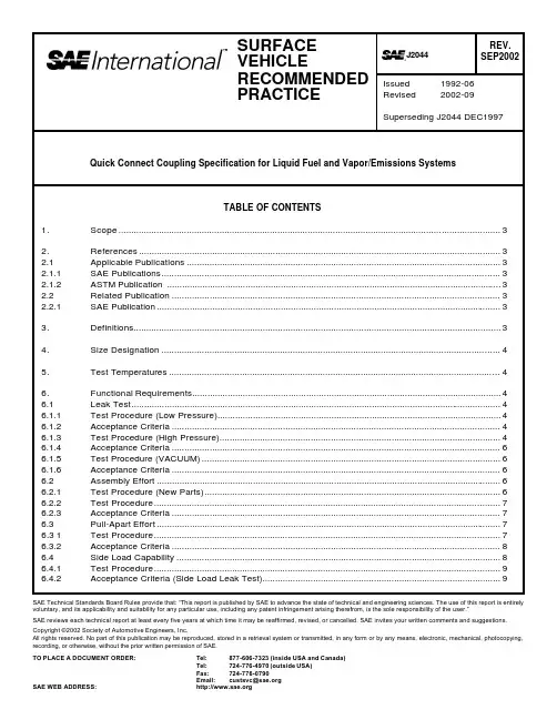
SAE Technical Standards Board Rules provide that: “This report is published by SAE to advance the state of technical and engineering sciences. The use of this report is entirely voluntary, and its applicability and suitability for any particular use, including any patent infringement arising therefrom, is the sole responsibility of the user.”SAE reviews each technical report at least every five years at which time it may be reaffirmed, revised, or cancelled. SAE invites your written comments and suggestions. Copyright ©2002 Society of Automotive Engineers, Inc.All rights reserved. No part of this publication may be reproduced, stored in a retrieval system or transmitted, in any form or by any means, electronic, mechanical, photocopying, recording, or otherwise, without the prior written permission of SAE.TO PLACE A DOCUMENT ORDER:Tel: 877-606-7323 (inside USA and Canada)Tel: 724-776-4970 (outside USA)Fax: 724-776-0790Email: custsvc@6.4.3Test Requirement (Side Load Fracture Test) (9)6.4.4Acceptance Criteria (9)6.5Resistance to Evaporative Emissions (10)6.5.1Test Procedure (10)6.5.2Acceptance Criteria (10)6.6Electrical Resistance (10)6.6.1Test Procedure (10)6.6.2Acceptance Criteria (10)7.Design Verification/Validation Testing (11)7.1Corrosion (11)7.1.1Test Procedure (11)7.1.2Acceptance Criteria (11)7.2Zinc Chloride Resistance (11)7.2.1Test Procedure (11)7.2.2Acceptance Criteria (11)7.3External Chemical and Environmental Resistance (11)7.3.1Test Procedure (11)7.3.2Fluid or Medium (12)7.3.3Acceptance Criteria (12)7.4Fuel Compatibility (12)7.4.1Test Procedure (12)7.4.2Test Fuels (12)7.4.3Test Requirement (12)7.4.4Acceptance Criteria (12)7.5Life Cycle (13)7.5.1Test Procedure (13)7.5.2Vibration Frequency (13)7.5.3Acceleration (13)7.5.4Vibration Duration (13)7.5.5Fluid Pressure (13)7.5.6Fluid Flow (Liquid Fuel Quick Connectors Only) (13)7.5.7Test Duration (13)7.5.8Test Cycle (14)7.5.9Acceptance Criteria (15)7.6Flow Restriction (16)7.7Elevated Temperature Burst (16)7.7.1Test Procedure (16)7.7.2Acceptance Criteria (17)8.Design Verification/Validation and In-Process Testing Matrix (17)9.Notes (17)9.1Marginal Indicia (17)Appendix A Mating Tube End Template Examples (18)1.Scope—This SAE Recommended Practice defines standard tube end form dimensions so as to guaranteeinterchangeability between all connector designs of the same size and the standard end form. This document also defines the minimum functional requirements for quick connect couplings between flexible tubing or hose and rigid tubing or tubular fittings used in supply, return, and vapor/emissions in fuel systems. This document applies to automotive and light truck applications under the following conditions:a.Gasoline and diesel fuel delivery systems or their vapor venting or evaporative emission controlsystems.b.Operating pressure up to 500 kPa, 5 bar, (72 psig).c.Operating vacuum down to –50 kPa, –0.5 bar (–7.2 psi).d.Operating temperatures from –40 °C (–40 °F) to 115 °C (239 °F).Quick connect couplings function by joining the connector to a mating tube end form then pulling back to assure a complete connection. The requirements stated in this document apply to new connectors in assembly operations unless otherwise indicated. For service operations, the mating tube should be lubricated with SAE 30-weight oil before re-connecting.NOTE—New connector designs using the same materials as previously tested connectors may use the original results as surrogate data for 7.1, 7.2, 7.3, and 7.4.Vehicle OEM fuel system specifications may impose additional requirements beyond the scope of this general SAE document. In those cases, the OEM specification takes precedence over this document.2.References2.1Applicable Publications—The following publications form a part of this specification to the extent specifiedherein. Unless otherwise specified, the latest issue of SAE publications shall apply.2.1.1SAE P UBLICATIO NS—Available from SAE, 400 Commonwealth Drive, Warrendale, PA 15096-0001.SAE J1645—Fuel System—Electrostatic ChargeSAE J1681—Gasoline, Alcohol, and Diesel Fuel Surrogates for Materials TestingSAEJ1737—Test Procedure to Determine the Hydrocarbon Losses from Fuel Tubes, Hoses, Fittings, and Fuel Line Assemblies by RecirculationSAE J2045—Performance Requirements for Fuel System Tubing Assemblies2.1.2ASTM P UBLICATION—Available from ASTM, 100 Barr Harbor Drive, West Conshohocken, PA 19428-2959.ASTM B 117—Method of Salt Spray (Fog) Testing2.2Related Publication—The following publication is provided for information purposes only and is not a requiredpart of this specification.2.2.1SAE P UBLICATIO N—Available from SAE, 400 Commonwealth Drive, Warrendale, PA 15096-0001.SAE J30—Fuel and Oil Hoses3.Definitions3.1Unexposed coupling—One that has not been used or deteriorated since manufacture.3.2Lot—A group of couplings that can be traced to a single assembly set-up or material lot. No more than oneweek production in a lot.4.Size Designation—The following system of size designations apply to the tube end and connector portions ofquick connect couplings. The connector size designation consists of two numbers. The first number designates the OD of the mating tube end. The second number designates the tubing size suited for the stem.EXAMPLE—9.5 mm x 8 mm connector fits a 9.5 mm male and 8 mm flexible tubing or hose. The mating tube end size designations refers to the nominal OD of the sealing surface. Refer to Figure 1 for anillustration of this Coupling Nomenclature.FIGURE 1—CONNECTOR NOMENCLATUREDetails for standard coupling sizes and dimensions for standard tube end forms are shown on Figure 2.NOTE—On metal or nonmetallic tubing, the OD is used to designate size and on flexible hose and tubing, the ID is used to designate size.5.Test Temperatures—Unless otherwise specified, all tests will be performed at room temperature 23 °C ± 2 °C(73.4 °F ± 4 °F).6.Functional Requirements—This section defines the minimum functional requirements for quick connectorcouplings used in flexible tubing fuel systems.6.1Leak Test—In order to provide a production compatible process, all leak testing should be performed usingcompressed air in a manner that insures the connectors will not leak liquid fuel or vapor.6.1.1T EST P ROCEDURE (L OW P RESSURE)a.Insert leak test pin, shown in Figure 3, into the connector.b.Pressurize between the seals with suitable air leak test equipment to 69 kPa ± 7 kPa, 0.69 bar ±0.07bar (10 psig ± 1 psig).NOTE—For single seal connectors, the stem must be capped or sealed.6.1.2A CCEP TANCE C RITERIA (L OW P RESS URE)—Maximum leak rate 2 cc/min at stabilization.6.1.3T EST P ROCEDURE (H IGH P RE SSURE)a.Insert leak test pin, shown in Figure 3, into the connector.b.For liquid fuel quick connector couplings, pressurize between the seals with suitable air leak testequipment to 1034 kPa ± 35 kPa, 10.34 bar ± 0.35 bar (150 psig ± 5 psig).c.For vapor/emission quick connector couplings, pressurize between the seals with suitable air leak testequipment to 138 kPa ± 10 kPa, 1.38 bar ± 0.10 bar (20 psig ± 2 psig).FIGURE 2—MATING TUBE FORM6.1.4A CCEP TANCE C RITERIA (H IGH P RESSURE)—Maximum leak rate 5 cc/min at stabilization.NOTE 1—For single seal connectors, the stem must be capped or sealed.NOTE 2—Appropriate safety precautions should be taken when testing with high-pressure air.6.1.5T EST P ROCEDURE (V ACUUM)a.Insert leak test pin shown in Figure 3 into connector.b.Apply a vacuum of 7 kPa with suitable vacuum leak test equipment.6.1.6A CCEP TANCE C RITERIA (V ACUUM)—Maximum leak rate 2 cc/min at stabilization.FIGURE 3—LEAK TEST PIN6.2Assembly Effort—Quick connect coupling assembly effort is the peak force required to fully assemble (latchor retain) the mating tube end into the connector. Use a suitable tensile/compression tester to verify conformance to this document.6.2.1T EST P ROCEDURE (N EW P ARTS)a.Test a minimum of 10 couplings.b.Test the quick connect coupling as supplied. Do not add additional lubrication to the quick connectcoupling or test pin.c.Attach quick connect coupling to a suitable test fixture.d.Wipe the test pins, before each test, with a clean lint-free cloth to prevent an accumulation oflubrication.e.Insert assembly test pin, shown in Figure 4, into the quick connect coupling at a rate of 51 mm/min ± 5mm/min (2 in/min ± 0.2 in/min) and measure assembly effort. (Simulated maximum tube end form)6.2.2T EST P ROCEDURE—Connectors after Section 7 exposure.a.Allow samples to dry 48 h before insertion testing.b.Lubricate test pin with SAE 30-weight oil by dipping the end in oil up to the retaining bead.c.Insert assembly test pin, shown in Figure 4, into the quick connector at a rate of 51 mm/min ± 5 mm/min (2 in/min ± 0.2 in/min) and measure assembly effort.6.2.3A CCEP TANCE C RITERIAa.Maximum first time assembly effort must not exceed 67 N (15 lb) for sizes <11 mm male tubes, and111 N (25 lb) for sizes ≥11 mm male tubes.b.Maximum assembly effort after Section 7 exposures must not exceed 111 N (25 lb) for <11 mm maletubes and 156 N (35 lb) for ≥11 mm male tubes.FIGURE 4—ASSEMBLY TEST PIN6.3Pull-Apart Effort—Quick connect coupling pull-apart effort is the peak force required to pull the mating tubeend out of the quick connect coupling. Use a suitable tensile tester to verify conformance to this document.For hose pull-off, see SAE J2045.6.3.1T EST P ROCEDUREa.Attach the quick connector body stem to a fixture suitable for pulling axially through the centerline ofthe quick connector.e the pull-apart test pin shown in Figure 5. (Simulated minimum mating end form)c.Apply a tensile load, at a rate of 51 mm/min ± 5 mm/min (2 in/min ± 0.2 in/min), until completeseparation occurs.6.3.2A CCEP TANCE C RITERIAa.Minimum Force P required to separate the test pin from the fuel quick connector should be, P = 56d upto a maximum of 600 N (135 lb) or for unexposed connectors and P = 37d up to a maximum of 400 N(90 lb) after Section 7 exposure where P = Force in Newtons and d = Nominal Tube Diameter inmillimeters.b.Minimum Force P required to separate the test pin from the vapor/emissions quick connector shouldbe P = 16d up to a maximum of 400 N (90 lb) for unexposed connectors, P = 12d up to a maximum of300 N (67 lb) after Section 7 exposure.FIGURE 5—PULL APART PIN6.4Side Load Capability—Quick connect couplings must be able to withstand side loads typical of what might beimposed by hose routing in a vehicle application as well as from having the hose pushed aside to reach other objects on the vehicle during service procedures. The connector side load capability is measured using a side load leak test and a side load fracture test. All connector designs and all tube end forms on metal or plastic molded parts must meet the requirements of this procedure.6.4.1T EST P ROCEDUREa.Insert quick connector into a length of design intent flexible tubing or hose with the opposite endsealed.b.Attach the quick connector to a suitable side load leak fixture or the plastic molded part, shown inFigure 6. (Simulated minimum end form)c.For liquid fuel quick connect couplings, pressurize the assembly with 1034 kPa ± 35 kPa, 10.34 bar ±0.35 bar (150 psig ± 5 psig) air pressure.d.For vapor/emission quick connect couplings, pressurize the assembly with 69 kPa ± 14 kPa, 0.69 bar± 0.14 bar (10 psig ± 2 psig) air pressure.e.Side load the hose or tube center point with the required load specified and perform the leak test.f.Mount a sample in the fracture fixture or plastic molded part, side load quick connector, at a rate of12.7 mm/min ± 5 mm/min (0.5 in/min ± 0.2 in/min), until the specified force is applied or fracture of thequick connector occurs. Kinking of design intent hose is permitted.6.4.2A CCEP TANCE C RITERIA (S IDE L OAD L EAK T ES T)a.No leaks, fracture, or rupture of the quick connector or its components or the plastic molded tube endpermitted below the minimum F = 19d up to maximum of 225 N (50 lb), where F = Side Load inNewtons and d = nominal tube diameter in millimeters.b.Maximum leak rate is 8 cc/min at stabilization with 10.34 bar ± 0.34 bar (150 psig ± 5 psig) appliedpressure for liquid connectors or 69 kPa ± 14 kPa, 0.69 bar ± 0.14 bar (10 psig ± 2 psig) appliedpressure for vapor connectors.6.4.3T EST R EQ UIREMENT (S IDE L OA D F RACTURE T EST)—Push above the end of the stem.6.4.4A CCEP TANCE C RITERIA—No fracture, rupture, or yield of the quick connector or its components or the plasticmolded tube end permitted, below the minimum of F = 28d up to a maximum of 400 N (90 lb), where F = Side Load in Newtons and d = nominal tube diameter in millimetersFIGURE 6—SIDE LOAD TEST FIXTURE6.5Resistance to Evaporative Emissions—Fuel line couplings are an integral part of the fuel system barrier toevaporative emissions. They are viewed as potential leak sites in the system. This method is to be used to determine hydrocarbon losses from permeation or micro leaks that are characteristic of each connector design.6.5.1T EST P ROCEDUREa.Because the losses from a single coupling are normally too small to measure accurately, it isrecommended that a test specimen be created consisting of 10 couplings. The value measured isthen divided by the number of connectors in the test specimen to arrive at the per connector value.b.Connector stem is to be inserted into the design intent flexible tubing or hose and a design intent tubeend inserted into the connector. The flexible tubing or hose should have its permeation propertiesmeasured independently using the same test fluid, preconditioning time and temperature, testtemperature and measurement technique. The value measure in this test is then corrected bysubtracting the permeation contribution from the flexible tubing.c.For the purpose of making the correction described in b. (previously) measure the length of flexibletubing in the test specimen that will be exposed to fuel during the test. For each section of flexibletubing this should be measured from a point half way up the stem on one connector to the same pointon the next connector in line.d.Precondition the test specimen per SAE J1737 until steady state permeation/leak measurements areobtained. Use Test Fluid C per SAE J1681. Precondition at 40 °C and 60 °C for separate tests ateach of those temperatures.e.Measure the hydrocarbon losses using a suitable SAE test method (i.e., SAE J1737, Mini-SHED,weight loss, etc) providing it is sufficiently accurate and the flexible tubing has been permeation testedusing the same method. Test at steady state temperatures of 40 °C and 60 °C.f.Correct the measured value for the multi-coupling test specimen by first subtracting the permeationvalue attributed to the flexible tubing then dividing that value by the number of couplings in the testspecimen.6.5.2A CCEP TANCE C RITERIA—None. Report value for each size and material combination only.6.6Electrical Resistance—If required by the OEM, all connectors used in fuel system applications involvingflowing liquid fuel must be sufficiently conductive and capable of creating an electrical connection with the flexible tubing into which they are inserted and with the tube end form that is inserted into them in order to prevent the buildup of harmful electrostatic charges.6.6.1T EST P ROCEDUREa.Test specimen is to consist of a coupling representative of the design as it will be installed in a vehicleapplication. The coupling is to be in the middle of the specimen. The length of both the flexible tubingor hose and rigid tubing must be 250 mm.b.Expose the specimens in accordance with 7.4 of this document then dry the exterior thoroughly.c.Measure electrical resistance per SAE J1645 between the inner surfaces at each end of the specimen.CAUTION—Measurement device may produce hazardous electrical charge, handle components with insulated means.d.With the measurement system in place and recording, using insulated tongs or grasping device, movethe connector both axially and tangentially with respect to the installed tube end.6.6.2A CCEP TANCE C RITERIAa.Measured resistance must be less than 106Ω (at 500 V).b.Electrical continuity must be maintained in all orientations of the connector relative to the tube end.c.Maintain material certification log to show in-process capability.7.Design Verification/Validation Testing7.1Corrosion—The corrosion test is performed to assure that the quick connector components will meet thefunctional requirements of the fuel system after exposure to the corrosion test.7.1.1T EST P ROCEDUREa.Insert design intent mating tube ends, shown in Figure 2, into the quick connect couplings.b.Cap the mating tube ends and the stem ends of the quick connect couplings, so internal surfacesremain free of water and corrosion.c.Perform salt spray test per ASTM B 117.7.1.2A CCEP TANCE C RITERIA—The quick connect couplings shall be capable of meeting the functionalrequirements of 6.1, 6.2, and 6.3 after 500 h salt spray. Appearance is not a functional requirement.7.2Zinc Chloride Resistance—Zinc chloride is an environmental stress-cracking agent to which somehygroscopic polymers are sensitive. This test is performed to assure that the quick connect couplings meets their functional requirements after exposure to zinc chloride.7.2.1T EST P ROCEDUREa.Insert mating tube ends, shown in Figure 2, into the quick connect couplings.b.Cap the mating tube ends and stem ends of the quick connect couplings, so internal surfaces remainfree of water and corrosion.c.Immerse the couplings in a 50% aqueous solution (by weight) of zinc chloride for 200 h at 23°C (roomtemperature). Cover or cap the container to prevent the solution from changing concentrationsignificantly during the exposure. When in doubt, measure the concentration of ZnCl at the completionof the test.d.When the exposure is complete, remove the quick connect couplings from the zinc chloride solution,do not rinse or clean.e.The quick connect couplings must then be held at room temperature for 24 h.f.Quick connect couplings are to be inspected after each exposure sequence for any evidence ofcracking.7.2.2A CCEP TANCE C RITERIAa.No cracks or fractures of the quick connector or its components permitted.b.The quick connect couplings shall be capable of meeting the functional requirements of 6.1, 6.2, and6.3 after exposure to zinc chloride.7.3External Chemical and Environmental Resistance—Quick connect couplings may be exposed to a range ofchemicals typical of the automotive environment. This chemical resistance test is performed to assure that the quick connect couplings will meet their functional after exposure to typical automotive fluids.7.3.1T EST P ROCEDUREa.Insert mating tube ends, shown in Figure 2, into the quick connect couplings.b.Cap mating tube ends and stem ends of the quick connect couplings.c.Submerge the quick connect coupling assemblies completely.d.At the end of 60 days, dry connectors at room temperature for 48 h.7.3.2F LUID OR M EDIUM—See Table 1.7.3.3A CCEP TANCE C RITERIA—The quick connect couplings shall be capable of meeting the functionalrequirements of 6.1, 6.2, and 6.3 upon completion of the external chemical and environmental testing.NOTE—New connector sizes using the same materials and architectural design as previously tested connectors may use the original results as surrogate data.TABLE 1—FLUID OR MEDIUM(1)Fluid or Medium Exposure Time ProcedureAutomatic Transmission Fluid60 Days Soak @ room tempMotor Oil60 Days Soak @ room tempBrake Fluid (Dot 3)60 Days Soak @ room tempEthylene Glycol (50% Water)60 Days Soak @ room tempPropylene Glycol (50% Water)60 Days Soak @ room tempDiesel Fuel60 Days Soak @ room tempEngine Degreaser60 Days Soak @ room temp1.The fluids in Table 2 shall be considered generic or those that are common to the industry.7.4Fuel Compatibility—The fuel compatibility test is performed to assure that the quick connector will meet thefunctional requirements of the fuel system after exposure to specific fuel blends.NOTE—The intention of the document is that all couplings be fully interchangeable. As such couplings must be qualified to operate with all available fuels. Connectors made of materials that are not suitable foruse in some fuels must be clearly labeled to identify their limitations.7.4.1T EST P ROCEDUREa.Insert mating tube ends, shown in Figure 2, into the connectors.b.The samples shall have fuel contact surfaces exposed to the fuels specified in 7.4.2, see Table 2.c.Replace the fuel every 7 days.d.New samples must be used for each test.7.4.2T EST F UE LS—Reference SAE J1681 and Table 2.7.4.3T EST R EQ UIREMENT—One-half the samples shall be tested immediately after removal from the test fuel andthe remaining samples shall be tested after a 48-h dry-out period.7.4.4A CCEP TANCE C RITERIA—The quick connect coupling shall meet the functional requirements of 6.1, 6.2, and6.3 after the completion of the fuel compatibility test.NOTE—New connector sizes using the same materials and architectural design as previously tested connectors may use the original results as surrogate data.TABLE 2—TEST FLUIDSTest Fluid (Per SAE J1681)Exposure Time ProcedureASTM Reference Fuel C60 Days Soak @ 40 °CSAE CE10 (Fuel C Plus 10% Ethyl Alcohol)60 Days Soak @ 40 °CSAE CM30 (Fuel C Plus 30% Methyl Alcohol)60 Days Soak @ 40 °CSAE CME15 (Fuel C Plus 15% MTBE)60 Days Soak @ 40 °CSAE CP (Auto-Oxidized Fuel)60 Days Soak @ 40 °C7.5Life Cycle—The life cycle test is performed to assure that the quick connector will meet the functionalrequirements of the fuel system when exposed to pressure, vibration, and temperature cycles typical of severe duty in automotive applications.7.5.1T EST P ROCEDUREa.Insert a connector in each end of a 500 mm (19.69 in) length of suitable flexible tubing.b.Leak test the assembly per 6.1, except use mating tube end shown in Figure 2.c.Connect the assembly to a test fixture, shown in Figure 7 using production intent tubes.d.Test fluid (liquid fuel quick connect couplings)—Mobil Arctic 155 refrigerant oil or equivalent.e.Test fluid (vapor/emission quick connect couplings)—Air.NOTE—Use of flammable materials is not recommended. However, tests in fuel or fuel surrogates can produce better results at low temperatures.7.5.2V IBRATIO N F REQUENCY—Continuously sweep the frequency from 7 Hz to 200 Hz, with 3 sweeps per hour. 7.5.3A CCELERATION—See Table 3.TABLE 3—ACCELERATION(1)Maintain Acceleration Load From To18 m/s2 (2 G)7 Hz25 Hz90 (10 G)2550182 (20 G) 5075163 (18 G) 75100145 (16 G)100125127 (14 G)125150109 (12 G)15017590 (10 G)1752001.This test may be interrupted or shut down for weekends at the end of anysection.7.5.4V IBRATIO N D URATION—Maintain vibration as specified in 7.5.8 (Test Cycles).7.5.5F LUID P RESSUREa.For liquid fuel quick connect couplings during pressure portions of the test, alternate pressure between0 and 1034 kPa ± 35 kPa, 10.34 bar ± 0.35 bar (150 psig ± 5 psig). Alternate pressure one time perminute (i.e., 1 min at each pressure).b.For vapor/emission quick connect couplings during pressure portions of the test, alternate pressurebetween 0 and 69 kPa ± 2 kPa, 0.69 bar ± 0.02 bar (10 psig ± 0.3 psig). Alternate pressure one timeminute (i.e., 1 min at each pressure).NOTE—Pressure transition rate is to be as close to a square wave as practical but not so abrupt that pressure overshoot occurs. This may require up to 3 s.7.5.6F LUID F LOW (L IQUID F UEL Q UICK C ONNECT C OUP LINGS O NLY)—Flow rate during the specified test cycle is1.33 Lpm ± 0.2 Lpm (0.46 gpm ± 0.07 gpm) through each quick connect coupling.7.5.7T EST D URATION—336 h (14 test cycles) (14 days)7.5.8T EST C YCLES—The test cycle consists of five sections to simulate hot operation, hot soak, hot operation afterhot soak, cold soak, and cold operation. See Table 4.NOTE—Included at the beginning of the hot and cold test sections are temperature transitions times of 1h maximum.7.5.8.1Hot Operation Testa.Length of Time—7 hb.Chamber Temperature—125 °C ± 5 °C (257 °F ± 9 °F)c.Fluid Temperature (liquid fuel quick connect couplings only)—66 °C ± 5 °C (151 °F ± 9 °F)d.Fluid Pressure—yese.Fluid Flow—yesf.Vibration—yes7.5.8.2Hot Soaka.Length of Time—2 hb.Chamber Temperature—125 °C ± 5 °C (257 °F ± 9 °F)c.Fluid Temperature (liquid fuel quick connect couplings only)—Heat to chamber temperatured.Fluid Pressure—yese.Fluid Flow—nof.Vibration—no7.5.8.3Hot Operation after Hot Soaka.Length of Time—7 hb.Chamber Temperature—125 °C ± 5 °C (25 7°F ± 9 °F)c.Fluid Temperature (liquid fuel quick connect couplings only)—66 °C ± 5 °C (151 °F ± 9 °F)d.Fluid Pressure—yese.Fluid Flow—yesf.Vibration—yes7.5.8.4Cold Soaka.Length of Time—7 hb.Chamber Temperature— –40 °C (-40 °F)c.Fluid Temperature (liquid fuel quick connect couplings only)—Cool to chamber temperatured.Fluid Pressure—yese.Fluid Flow—nof.Vibration—no7.5.8.5Cold Operationa.Length of Time—1 hb.Chamber Temperature— –40 °C (–40 °F)c.Fluid Temperature (liquid fuel quick connect couplings only)—Cool to chamber temperatured.Fluid Pressure—yese.Fluid Flow—yesf.Vibration—yes7.5.9A CCEP TANCE C RITERIAa.No fluid leaks permitted during or at completion of test, for Vapor connector couplings, air leak test per6.1.b.The connector shall meet the functional requirements of 6.1, 6.2, and 6.3 after the completion of thelife cycle test.c.Perform visual inspection of connector and its components. No fractures, cracks, or unusual wearpermitted.FIGURE 7—LIFE CYCLE TEST SET UP7.6Flow Restriction—Quick connect couplings shall be designed to provide minimal flow restriction. 7.6.1T EST P ROCEDURE a.Insert connector into its intended flexible tubing.b.Connect the flexible tubing to a source for controlled flow of water.c.Measure the pressure required to create 120 L/h flow through each connector design.7.6.2A CCEP TANCE C RITERIA —None. Measure and report value.7.7Elevated Temperature Burst—The elevated temperature burst test is performed to assure that the quick connect coupling will withstand the pressure requirements of the fuel system at the maximum operating temperature. This test can be performed as part of the tube and hose assembly requirements of SAE J2045 or as follows.7.7.1T EST P ROCEDURE a.Insert a quick connector in each end of a 500 mm (19.69 in) length of tubing or reinforced fuel hose.Secure each end with a hose clamp if required, to prevent failure of the stem to hose interface.b.Insert male tube ends, shown in Figure 2, into the quick connect couplings.c.Attach assembly to a suitable, air or hydraulic, burst pressure source.d.Place the assembly in a suitable environmental chamber and soak at 115 °C (239 °F) for 1 h.e.Perform burst by pressurizing the hose assembly at a rate of 3450 kPa/min (500 psig/min) until burst or rupture occurs.TABLE 4—LIFE CYCLE TEST SCHEDULESection Hour Chamber TemperatureFluid TemperatureFluid PressureFluid FlowVibration 7.5.8.11 125 °C (1)1.Temperature may be in transition.125 °C (1)Yes Yes Yes 2125°66°Yes Yes Yes 3125°66°Yes Yes Yes 4125°66°Yes Yes Yes 5125°66°Yes Yes Yes 6125°66°Yes Yes Yes 7125°66°Yes Yes Yes 7.5.8.28125°125°(1)Yes No No 9 125°125°Yes No No 7.5.8.310125°66°(1)Yes Yes Yes 11125°66°Yes Yes Yes 12125°66°Yes Yes Yes 13125°66°Yes Yes Yes 14125°66°Yes Yes Yes 15125°66°Yes Yes Yes 16125°66°Yes Yes Yes 7.5.8.417–40 °C (1)–40°(1)Yes No No 18–40°–40°Yes No No 19–40°–40°Yes No No 20–40°–40°Yes No No 21–40°–40°Yes No No 22–40°–40°Yes No No 23–40°–40°Yes No No 7.5.8.524–40°–40°YesYesYes。
汽车发动机燃油系统的工作原理汽车发动机燃油系统是确保发动机正常运转的关键部件之一。
它的主要功能是将燃油从燃油箱传送到发动机,并在发动机工作时提供适量的燃油。
燃油系统包括燃油箱、燃油泵、燃油滤清器、喷油器等多个部件,它们共同协作,保证发动机燃油供应的稳定性和可靠性。
燃油系统的工作原理可以分为四个主要过程:供油、过滤、喷射和调节。
第一,供油过程。
燃油系统的燃油供应始于燃油箱。
燃油箱通常位于车辆底部,通过燃油泵将燃油从燃油箱中抽取,并通过燃油管路输送至发动机。
燃油泵的工作原理是利用电动或机械的方式产生压力,将燃油送入燃油滤清器。
第二,过滤过程。
燃油滤清器的作用是过滤掉燃油中的杂质和颗粒物,确保燃油的干净和纯净。
燃油滤清器通常由滤芯和滤壳组成,滤芯是由纤维材料制成的,可以有效地过滤掉燃油中的杂质。
经过滤清器过滤后的燃油将进入喷油器。
第三,喷射过程。
喷油器位于发动机进气道上方,其作用是将燃油以恰当的方式喷射到发动机的气缸中。
喷油器内部有一个电磁阀,通过控制电磁阀的开启和关闭来控制喷油量。
当发动机工作时,电控单元会根据发动机的工作状态和负荷情况来控制喷油器的喷油量和喷油时机,以确保燃油的最佳喷射效果。
第四,调节过程。
燃油系统还具备调节燃油供应量的功能,以满足不同工况下发动机的需求。
发动机的负荷和转速变化都会对燃油供应量产生影响,因此需要通过调节燃油压力或喷油器的喷油量来实现燃油供应的调节。
现代汽车燃油系统通常配备了电控单元,它通过传感器检测发动机的工作状态和环境条件,并根据这些信息来调整燃油供应量,以实现燃油的经济性和动力性的平衡。
总结起来,汽车发动机燃油系统的工作原理包括供油、过滤、喷射和调节四个主要过程。
这些过程的协同作用保证了发动机正常运转所需的燃油供应。
燃油系统的稳定性和可靠性对发动机的性能和寿命有着重要影响,因此对燃油系统的维护和保养至关重要。
定期更换燃油滤清器、清洗喷油器等维护措施能够保持燃油系统的良好状态,确保发动机的正常工作。
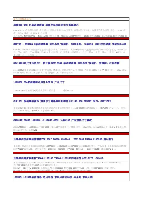
录入日期2015/5/9奔驰R90-MER-01柴油滤清器 奔驰发电机组油水分离器滤芯R90-MER-01 产品图片参照 类目属性:柴油滤清器/油水分离器 适用车型/发动机:奔驰系列发电机组 外径:107mm 高度:213mm 螺纹:M16×1.5 止回阀原件编号:R90-MER-01 Benz:A000 477 13 02 Nissan:16403-NY000 Isuzu:897605118 Daewoo:65.12501-5021 65 12503-5100 1125010-F57K0 FS19737 FS19591 SFC1813 P551746 PFF5602 R90-MER-01 R120-D-DAE-01 R120-D1-03 S3211CX0706 、CX0706-1柴油滤清器 适用车型/发动机:TC87系列、大柴498 福田时代驭菱 莱动380/480CX0706、CX0706-1柴油滤清器适用车型/发动机:TC87系列、大柴498福田时代驭菱莱动380/480产品尺寸螺纹 CX0706 外径:77mm 高度:77mm 螺纹:M16×1.5 止回阀:无 旁通阀:CX0706-1 外径:77mm 高度:87mm 螺纹:M16×1.5止回阀:无 旁通阀:无5041995510尺寸是多少?.豹王编号TF-8944 柴油滤清器 适用车型/发动机:依维柯、红岩杰狮5041995510柴油滤清器适用车型/发动机:依维柯、红岩杰狮产品尺寸螺纹 豹王滤清器编号是TF-8944 外径:94mm 高度:207mm 螺纹:M16×1.5 止回阀:无 旁通阀:无 产品图片参照1105050-50A燃油滤清对用什么型号 产品尺寸1105050-50A燃油滤清对用什么型号产品尺寸 对应PL420CLX-201 旋装柴油滤芯 燃油水分离器康明斯零件号1119G-030 FF5327 国内:CX0710F2.平原牌CLX-201旋装柴油滤芯燃油水分离器适用于康明斯零件号1119G-030FF5327国内编号:CX0710F2 产品尺寸: 外径*高:77*145 螺纹:M16*1.5 放水螺母:M14CX0817E D2000-1105240 b1117050-d535 玉柴4108 产品规格尺寸螺纹CX0817ED2000-1105240b1117050-d535玉柴4108产品规格尺寸螺纹 直径:85mm高度:200mm螺纹尺寸:M16*1.5技术标准:欧三适用车型:玉柴4105玉柴柴油机用柴油滤清器YCX-6607 FG200-1105140 YCX-6608 FG200-1105350.通用型号.玉柴的,柴油机用柴油滤清器YCX-6607FG200-1105140YCX-6608FG200-1105350通用型号,产品尺寸 玉柴柴油滤清器YCX-6607FG200-1105140: 通用型号有,CX0816E 4897833 FF5485 FF5612 612600081334 螺纹M20*1.5 ..玉柴柴油滤清器组件T9000-1105140 T9000-1105350的通用型号CX1017F CX1017.玉柴柴油滤清器组件T9000-1105140-937(YCX-6531)的通用型号CX1017F 玉柴柴油滤清器组件T9000-1105350-937型式:YCX-6532适用车型:YC6T450C-20的通用型号:CX1017 CX1017A CX1017E 玉柴欧三 VG1540080211 UC-4035 1105-00159 玉柴:G5800-1105240(c) 重汽:VG1540080211上柴:D00-305-02+A互换:YCX6360;W0002 宇通客车YCCB1011000195011025BF11-020柴油滤清器 适用车型 东风风神发动机 4H系列 东风天锦所属类别:柴油滤清器 适用车型/发动机:东风风神发动机4H系列东风天锦 产品尺寸(高*外径*内径*罗纹):142.5*93*M20*1.5 原厂件号码:1025BF11-02016403-NY000 R120FG03燃油滤清器 燃油水分离器产品尺寸16403-NY000R120FG03燃油滤清器燃油水分离器产品尺寸 通用型号: 尼桑:16403-NY000, 弗列加滤清器:FS19754 DONALDSON唐纳森滤清器:P55-1746 亨斯特滤清器:H7120WK30 MANN滤清器:WK1175X,WK11002X RACOR滤清器:R120P,R120FG03,PFF5602FS1280柴油滤清器 适用车型 康明斯6BT.6CT 油水分离器所属类别:柴油滤清器 适用车型/发动机:康明斯6BT.6CT油水分离器 产品尺寸(高*外径*内径*罗纹):162/135*94*13/16〞-18 原厂件号码:3925274 FS1280 CX0809 CX0811A借用FF5052柴油滤清器 适用车型 康明斯6BT.6CT 柴油格所属类别:柴油滤清器 适用车型/发动机:康明斯6BT.6CT柴油格 产品尺寸(高*外径*内径*罗纹):115*76*M16*1.5 原厂件号码:FF5052 CX0710F1ME006066柴油滤清器 适用车型 三菱4D30.4DR5所属类别:柴油滤清器 适用车型/发动机:三菱4D30.4DR5 现代挖机 产品尺寸(高*外径*内径*罗纹):81*90*M20*1.5 原厂件号码:ME006066 129907-55800 31945-41020ME035829柴油滤清器 适用车型 三菱FK415 6D14 &..所属类别:柴油滤清器 适用车型/发动机:三菱FK415/6D14.6D15 加藤HD700-5.7/6D14.6D31 产品尺寸(高*外径*内径*罗纹):125*90*M20*1.5 原厂件号码:ME035393 ME035829 ME015254 ME240521 KS568C ME0168238-94414-796-3柴油滤清器 适用车型 五十铃 卡特 E200B 小松所属类别:柴油滤清器 适用车型/发动机:五十铃NHR.NKR/4JA1.4JB1 卡特E200B.小松PC60-5 羊城金星货车双排座 产品尺寸(高*外径*内径*罗纹):90*83*3/4"-16 原厂件号码:8-94414-796-3/0 600-311-7440 8-94167400-1 600-311-7441 0559-23-570WF2074柴油滤清器 适用车型 康明斯V28、NT855所属类别:柴油滤清器 适用车型/发动机:康明斯V28、NT855 产品尺寸(高*外径*内径*罗纹):135*93*11/16"-16 原厂件号码:WF2073 WF2074 WF2075 P552075WF2072柴油滤清器 适用车型 康明斯系列 解放J6、天龙所属类别:柴油滤清器 适用车型/发动机:康明斯系列 解放J6、天龙 产品尺寸(高*外径*内径*罗纹):103.5*93*11/16"-16 原厂件号码:WF2071C WF2072 P552071 3315116 .FS19544燃油水分离器和哪一个通用?产品尺寸,适用车型。
汽车燃油供给系统的故障诊断与修复技巧汽车作为现代社会中重要的交通工具,其性能的稳定与否直接关系到我们的出行安全和效率。
燃油供给系统作为汽车发动机的重要组成部分,负责为发动机提供适量、清洁的燃油,一旦出现故障,会导致发动机工作异常,影响汽车的动力性、经济性和排放性能。
因此,掌握汽车燃油供给系统的故障诊断与修复技巧对于汽车维修人员和车主来说都具有重要意义。
一、汽车燃油供给系统的组成及工作原理汽车燃油供给系统主要由燃油箱、燃油泵、燃油滤清器、燃油压力调节器、喷油器以及燃油管路等组成。
燃油箱用于储存燃油,燃油泵将燃油从燃油箱中吸出,并加压输送到燃油滤清器。
燃油滤清器的作用是过滤燃油中的杂质和污染物,确保进入发动机的燃油清洁。
经过过滤的燃油在燃油压力调节器的调节下,保持稳定的压力,然后通过喷油器喷射到发动机的进气道或气缸内,与空气混合后燃烧。
在这个过程中,燃油压力调节器根据发动机的工况和负荷,调整燃油压力,以保证燃油的供给量与发动机的需求相匹配。
喷油器则根据发动机控制单元(ECU)的指令,精确控制燃油的喷射时间和喷射量,实现最佳的燃烧效果。
二、常见故障类型及表现1、燃油压力异常燃油压力过高或过低都会导致发动机工作不正常。
燃油压力过高可能会造成喷油器喷射量过大,使混合气过浓,发动机冒黑烟、油耗增加;燃油压力过低则会导致喷油器喷射量不足,混合气过稀,发动机动力不足、加速不良,甚至无法启动。
2、喷油器故障喷油器堵塞会导致燃油喷射不畅,发动机工作不稳、抖动;喷油器泄漏则会使燃油未经正常喷射而直接进入气缸,造成混合气过浓,发动机冒黑烟、油耗增加。
3、燃油泵故障燃油泵磨损或损坏会导致供油不足,发动机动力下降、启动困难甚至无法启动;燃油泵工作噪声过大也可能是其出现故障的征兆。
4、燃油滤清器堵塞燃油滤清器堵塞会导致燃油流通不畅,供油压力下降,发动机动力不足、加速不良。
5、燃油管路泄漏燃油管路泄漏会导致燃油压力下降,发动机工作不稳,甚至可能引发火灾等安全隐患。
![长城GW2[1].8TC发动机零件图(CRS2.0)](https://uimg.taocdn.com/e55e2018b7360b4c2e3f64b6.webp)
保养卡车的技巧保养卡车是保证其正常运行和延长使用寿命的重要环节。
下面将为您详细介绍保养卡车的技巧。
第一,定期更换机油和机油滤清器。
机油是润滑发动机的关键,定期更换能有效减少摩擦和磨损,保护发动机。
而机油滤清器则能过滤掉机油中的杂质,防止其进入发动机内部,保持机油的清洁状态。
一般建议每行驶5000公里或3个月更换一次机油和机油滤清器。
第二,检查和更换空气滤清器。
空气滤清器能过滤空气中的灰尘和颗粒物,防止其进入发动机燃烧室,保护发动机。
如果空气滤清器堵塞,会导致空气供应不足,影响燃烧效率和动力输出。
建议每行驶1万公里或6个月检查和清洁一次滤清器,如果滤芯损坏或污垢较多,则需要更换滤清器。
第三,检查和更换燃油滤清器。
燃油滤清器能过滤燃油中的杂质和水分,防止其进入喷油系统和发动机,提供清洁的燃油供应。
如果燃油滤清器堵塞,会导致燃油供应不稳定,影响燃烧效率和动力输出。
建议每行驶1万公里或6个月检查和更换一次燃油滤清器。
第四,保持轮胎正常状态。
轮胎是卡车行驶的重要组成部分,如果轮胎磨损严重或出现裂纹,则需要及时更换。
保持轮胎的气压也非常重要,气压过高或过低都会影响操控性能和燃油经济性。
建议每月检查一次轮胎的磨损和气压,并定期做轮胎的旋转和平衡。
第五,保持车身干净。
卡车外部的污垢和尘埃会附着在车身上,如果不及时清洗,会影响车漆的质量和降低车身的抗锈性能。
建议每周洗车一次,注意清洗车身的每个角落和隐蔽部位,还可以定期给车身打蜡,增加保护层。
第六,定期检查和更换刹车片和刹车油。
刹车是卡车行驶过程中的重要保证,如果刹车片磨损严重或刹车油油质变差,则会影响制动性能和安全性。
建议每行驶1万公里或6个月检查刹车片的磨损情况,并根据实际情况更换刹车片和刹车油。
第七,定期清洗和更换冷却系统的冷却液。
卡车冷却系统的冷却液能有效降低发动机的温度,防止过热。
定期清洗和更换冷却液,可以保持冷却系统的正常运行和防止结垢。
建议每行驶2万公里或12个月清洗和更换一次冷却液。
汽车喷油系统故障的常见原因及维修手段汽车喷油系统是现代汽车发动机燃油供给的关键部件之一。
它负责将燃油喷入汽缸内,以供发动机正常燃烧。
然而,由于各种原因,喷油系统可能会出现故障,导致汽车性能下降甚至无法正常行驶。
本文将探讨汽车喷油系统故障的常见原因以及相应的维修手段。
一、喷油系统故障的常见原因1. 燃油滤清器堵塞燃油滤清器的作用是过滤燃油中的杂质,防止其进入喷油嘴和燃烧室,从而保护发动机正常运行。
然而,长时间未更换燃油滤清器或者使用低质量燃油,都可能导致其堵塞。
堵塞的燃油滤清器会导致燃油供应不足,进而影响喷油系统的工作。
2. 喷油嘴堵塞喷油嘴是喷油系统中的关键部件,负责将燃油以适当的压力和雾化度喷入燃烧室。
然而,由于长时间使用低质量燃油或者进气系统中的杂质堵塞,喷油嘴会出现堵塞现象。
堵塞的喷油嘴会导致燃油无法正常喷射,从而影响汽车的燃烧效率和动力表现。
3. 燃油泵故障燃油泵是喷油系统中的核心部件,负责将油箱中的燃油送至发动机燃油供应系统。
燃油泵故障可能导致燃油供应不足或无法正常启动,从而影响汽车的动力输出。
4. 燃油压力调节器故障燃油压力调节器是喷油系统中的重要组成部分,用于调节燃油供应系统的压力。
如果燃油压力调节器故障,就会导致燃油供应系统的压力异常,从而影响喷油量和喷油压力的稳定性。
5. 电子控制单元(ECU)故障电子控制单元是喷油系统的大脑,负责监测和控制燃油喷射的时机和量。
如果ECU故障,就无法正常调节喷油系统的工作状态,从而导致燃油供应不稳定或无法正常工作。
二、喷油系统故障的维修手段1. 更换燃油滤清器如果燃油滤清器堵塞,应立即更换新的滤清器。
同时,定期更换燃油滤清器也是预防堵塞的有效手段。
选择质量可靠的滤清器,并按照汽车制造商的建议进行更换。
2. 清洗喷油嘴对于堵塞的喷油嘴,可以采用专业的清洗剂进行清洗。
将清洗剂加入油箱中,然后按照相关要求进行操作。
清洗喷油嘴能够恢复其正常工作状态,提高燃油的喷射效果。
柴油机的保养方法柴油机是一种利用压燃燃料引起热机械能的内燃机,因其功率大、耐用等特点被广泛应用于各个领域。
然而,柴油机的维护保养却是一项重要的工作,直接关系到柴油机的性能和使用寿命。
本文将介绍柴油机的保养方法,以便延长柴油机的使用寿命。
一、机油更换机油是柴油机运行中最重要的润滑剂之一,它可以减少摩擦和磨损,冷热循环时也能够保护机器零部件。
在使用过程中,长时间的磨擦摩擦也会使机油的性能下降,这时候应及时更换机油,以免造成零部件损坏。
一般来说,应该每经过5000到10000公里就更换一次机油。
二、空气滤清器更换空气滤清器的作用是过滤进入柴油机内的空气,保持机器零部件的清洁,起到延长维护周期的作用。
柴油机的空气滤清器应根据使用条件定期检查和更换,避免灰尘、沙土和其他杂质进入汽油滤清器内部,影响柴油机运行。
三、燃油滤清器更换燃油滤清器的作用是保护柴油机的高精度燃油喷射器,防止进入燃油中的杂质和水分对燃油系统造成损害。
在使用状况下,燃油滤清器应该每千公里进行更换,以确保柴油机的稳定性和正常运行。
如果柴油机运行时有异响或抖动的情况,可能是因为燃油滤清器过脏而导致的,此时应及时进行更换。
四、维护柴油机水箱在使用柴油机时,重要的一点是要注意柴油机水箱的情况。
不及时清理柴油机水箱里面的沉淀物和泥沙,将影响柴油机的功率和燃油效率,还可能导致冷却不足的相应问题的出现,因此柴油机水箱应根据使用情况及时进行清理,以保持柴油机的正常运行。
五、及时更换喷油嘴喷油嘴是柴油机燃油系统中的重要零部件之一,能够控制汽油喷射和燃烧进程,使柴油机正常运行。
如果喷油嘴损坏,将导致排气量、油耗增加,同时还会引起燃油喷射系统的故障,从而使柴油机损坏的可能性增加。
因此,在使用柴油机时,喷油嘴应遵循每年至少检测一次的原则,有必要时更换喷油嘴。
六、其他维护细节除了以上几点,使用柴油机还应注意以下几个细节问题:1、新车应不定期更换燃油过滤器,释放积气和泥沙,以延长柴油机的使用寿命。
发动机外围部件的名称及作用一、进气系统1. 进气管道:将空气引入发动机内部,为燃烧提供氧气。
2. 进气滤清器:过滤进入发动机的空气,阻止灰尘、污物等杂质进入燃烧室,保护发动机。
3. 进气歧管:将进气管道中的空气分配到各个气缸中。
二、燃油系统1. 燃油箱:储存汽车所需的燃料。
2. 燃油泵:将燃油从燃油箱抽取并送到发动机的燃油供给系统中。
3. 燃油滤清器:过滤燃油中的杂质,防止杂质进入燃油系统和发动机内部。
4. 燃油喷射器:将燃油雾化并喷射到燃烧室中,实现燃烧过程。
三、点火系统1. 点火线圈:将低电压转换为高电压,以点燃燃烧室中的混合气体。
2. 火花塞:产生电火花点燃混合气体,引发燃烧反应。
四、冷却系统1. 水箱:储存冷却液,用于散热。
2. 水泵:循环冷却液,保持发动机正常工作温度。
3. 散热器:通过散热片将冷却液中的热量散发到空气中,保持发动机温度稳定。
4. 风扇:增加散热器的散热效果,降低发动机温度。
五、润滑系统1. 机油箱:储存机油,为发动机各个运动部件提供润滑。
2. 机油泵:将机油从油箱抽取并送到发动机各个润滑部位。
3. 机油滤清器:过滤机油中的杂质,保持机油的清洁。
4. 油底壳:存储和冷却机油,防止机油过热。
六、排气系统1. 排气管道:引导燃烧产生的废气排出。
2. 中段消声器:减少排气噪音。
3. 尾段消声器:降低排气噪音,改善尾气排放。
七、传动系统1. 变速器:将发动机的动力输出到车轮上,实现汽车的前进与倒退。
2. 驱动轴:将变速器的输出转移到车轮上,驱动车辆行驶。
八、辅助部件1. 发电机:通过转动发电机产生电能,为汽车电器设备供电。
2. 空调压缩机:压缩制冷剂,使其成为高温高压气体,为车内提供制冷效果。
3. 动力转向泵:为液压助力转向系统提供动力,减轻驾驶员的转向力。
4. 真空助力泵:为制动系统提供真空动力,增加制动器的制动效果。
以上是发动机外围部件的名称及作用。
这些部件共同协作,确保发动机的正常运转,为汽车提供动力,并保证汽车的安全性和舒适性。
机油汽油柴油空气滤清器产品参数机油滤清器产品参数:1.滤清效率:机油滤清器的滤清效率是指对机油中的微小颗粒和杂质进行过滤的能力。
通常以一个百分比来表示,例如98%。
这意味着滤清器可以过滤掉机油中的98%的微小颗粒和杂质。
2.流量能力:机油滤清器的流量能力是指其在单位时间内能够过滤的机油的量。
一般以立方米/小时或者加仑/分钟来表示。
流量能力越大,表示滤清器的工作效率越高。
3.寿命:机油滤清器的寿命是指其可以使用的时间或者里程数。
一般以小时或者公里数来表示。
寿命越长,表示滤清器的使用寿命越长,需要更少的更换。
4.压力损失:机油滤清器会阻碍机油的流动,导致一定的压力损失。
压力损失越低,表示滤清器的阻力越小,对发动机的影响也越小。
汽油滤清器产品参数:1.滤清效率:汽油滤清器的滤清效率是指对汽油中的微小颗粒和杂质进行过滤的能力。
通常以一个百分比来表示,例如98%。
这意味着滤清器可以过滤掉汽油中的98%的微小颗粒和杂质。
2.流量能力:汽油滤清器的流量能力是指其在单位时间内能够过滤的汽油的量。
一般以立方米/小时或者加仑/分钟来表示。
流量能力越大,表示滤清器的工作效率越高。
3.寿命:汽油滤清器的寿命是指其可以使用的时间或者里程数。
一般以小时或者公里数来表示。
寿命越长,表示滤清器的使用寿命越长,需要更少的更换。
4.压力损失:汽油滤清器会阻碍汽油的流动,导致一定的压力损失。
压力损失越低,表示滤清器的阻力越小,对发动机的影响也越小。
柴油滤清器产品参数:1.滤清效率:柴油滤清器的滤清效率是指对柴油中的微小颗粒和杂质进行过滤的能力。
通常以一个百分比来表示,例如98%。
这意味着滤清器可以过滤掉柴油中的98%的微小颗粒和杂质。
2.流量能力:柴油滤清器的流量能力是指其在单位时间内能够过滤的柴油的量。
一般以立方米/小时或者加仑/分钟来表示。
流量能力越大,表示滤清器的工作效率越高。
3.寿命:柴油滤清器的寿命是指其可以使用的时间或者里程数。
5系7万公里保养内容
根据车辆的具体情况和厂家的建议,以下是5系7万公里保养可能包含的内容:
1. 更换机油和机滤:根据厂家建议,约7万公里时需要更换机油和机滤。
新机油可以保持发动机的正常运转,机滤可以阻止灰尘和杂质进入发动机。
2. 更换空气滤清器:空气滤清器会随着使用时间的增加而积累灰尘和污垢,7万公里时建议更换空气滤清器,以确保引擎能够获得充足的新鲜空气。
3. 更换燃油滤清器:燃油滤清器的作用是过滤燃油中的杂质,防止进入燃油系统,保护喷油嘴和燃油泵等关键部件。
7万公里时建议更换燃油滤清器。
4. 检查并更换火花塞:火花塞是引擎点火系统的重要组成部分,7万公里时需要检查火花塞的状况,如果有必要,可以更换新的火花塞。
5. 更换制动油和制动片:制动油会随着时间的推移和使用而老化,7万公里时建议更换制动油,以保持制动系统的正常运行。
此外,制动片也会随着使用而磨损,7万公里时需要检查制动片的磨损情况,并根据需要进行更换。
6. 检查并更换悬挂系统的零部件:悬挂系统的零部件会随着使用时间的增加而磨损,7万公里时需要检查悬挂系统的状况,如悬挂弹簧、减震器等,并根据需要进行更换。
7. 检查并更换传动系统的零部件:传动系统的零部件会随着使用时间的增加而磨损,7万公里时需要检查传动系统的状况,如离合器、变速器等,并根据需要进行更换。
以上仅为一般情况下的保养内容,具体的保养项目可能会因车辆型号、使用环境和个人需求而有所不同。
建议根据车辆的实际情况和厂家的保养手册进行具体的保养安排。
车辆进水需要更换的零件车辆进水是一个常见的问题,如果不及时处理,可能会导致严重的损坏。
当车辆进水后,很多零部件都可能需要更换。
下面是一些常见的车辆进水需要更换的零件。
1. 发动机气缸垫片:当车辆进水后,水可能会进入发动机内部,导致气缸垫片受损。
如果发动机气缸垫片受损,会导致水和机油混合,影响发动机正常工作。
因此,需要更换发动机气缸垫片。
2. 空气滤清器:车辆进水后,空气滤清器可能会被水淹没,导致无法正常过滤空气。
如果空气滤清器受损,会导致发动机进气不畅,影响燃烧效率。
因此,需要更换空气滤清器。
3. 燃油滤清器:车辆进水后,燃油滤清器可能会被水淹没,导致无法正常过滤燃油。
如果燃油滤清器受损,会导致燃油中杂质进入燃烧室,影响燃烧效率。
因此,需要更换燃油滤清器。
4. 空调系统零件:车辆进水后,空调系统中的零件可能会受到损坏。
例如,空调压缩机、冷凝器等零件可能会被水淹没,导致无法正常工作。
因此,需要更换空调系统中受损的零件。
5. 制动系统零件:车辆进水后,制动系统中的零件可能会受到损坏。
例如,刹车盘、刹车片等零件可能会被水淹没,导致无法正常制动。
因此,需要更换制动系统中受损的零件。
6. 电子设备:车辆进水后,电子设备可能会受到损坏。
例如,发动机控制单元、仪表盘等电子设备可能会被水淹没,导致无法正常工作。
因此,需要更换受损的电子设备。
7. 底盘系统零件:车辆进水后,底盘系统中的零件可能会受到损坏。
例如,底盘悬挂、转向系统等零件可能会被水淹没,导致无法正常工作。
因此,需要更换底盘系统中受损的零件。
8. 轮胎:车辆进水后,轮胎可能会受到损坏。
例如,轮胎内部可能会积水,导致轮胎失去平衡。
因此,需要更换受损的轮胎。
9. 车灯:车辆进水后,车灯可能会受到损坏。
例如,前大灯、尾灯等车灯可能会被水淹没,导致无法正常工作。
因此,需要更换受损的车灯。
10. 座椅和内饰:车辆进水后,座椅和内饰可能会受到损坏。
例如,座椅填充物可能会吸水膨胀,导致变形。
燃油滤清器
作用:
其作用是滤除发动机燃油气系统中的有害颗粒和水份,以保护油泵油嘴、缸套、活塞环等,减少磨损,避免堵塞。
把含在燃油中的氧化铁、粉尘等固体杂物除去,防止燃油系统堵塞(特别是喷油嘴)。
减少机械磨损,确保发动机稳定运行,提高可靠性。
即使柴油在加入柴油机油箱前经过了沉淀和过滤,是清洁的,但是在加油过程中,由于加油工具、加油环境、油箱口不清洁等因素仍会使柴油污染,而且在柴油机运转过程中,由于燃油系统中沉积的杂质、空气中悬浮的沉埃,也会使柴油污染,因此车上的柴油滤清器是必不可少的,何况柴油在加入油箱前并不一定是真正清洁的。
种类:
燃油滤清器有柴油滤清器、汽油滤清器和天然气滤清器三类。
柴油滤清器的结构大致与机油滤清器相同,有可换式和旋装式两种。
但其承受的工作压力和耐油温要求较机油滤清器低得多,而其过滤效率的要求却比机油滤清器高得多。
柴油滤清器的滤芯多采用滤纸,也有采用毛毡或高分子材料的。
柴油滤清器除过滤柴油中的机械杂质外,还有一个重要的功能就是滤水,为实现较高分离效率,目前多采用两级式过滤方式,一级为油水分离器,一级为柴油精滤器。
水的存在对于柴油机供油系统危害极大,锈蚀、磨损、卡死甚至会恶化柴油的燃烧过程。
柴油滤清系统的除水方式在机械燃油系统主要是沉淀,到国三以上排放时代,柴油发动机多采用高压共轨燃油系统,除水方式多采用滤纸。
目前满足国三以上排放发动机要求的水分离器多为外企企业生产,如博世(BOSCH),曼胡(Mann-Hummel),帕克(Parker),国内品牌有达菲特(DIFITE)。
汽油滤清器有化油器式和电喷式之分,使用化油器的汽油发动机,汽油滤清器位于输油泵进口一侧,工作压力较小,一般采用尼龙外壳,电喷式发动机的汽油滤清器位于输油泵的出口一侧,工作压力较高,通常采用金属外壳。
汽油滤清器的滤芯多采用滤纸,也有使用尼龙布、高分子材料的。
工作原理:
燃油滤清器是串联在然油泵和节流阀体进油口之间的管路上。
燃油滤清器的作用,是把含在燃油中的氧化铁、粉尘等固体杂物除去,防止燃油系统堵塞(特别是喷油嘴)。
减少机械磨损,确保发动机稳定运行,提高可靠性。
燃油器的结构是一个铝壳和一个内有不锈刚的支架组成,在支架上装有高效滤纸片组成,滤纸片成菊花形,以增大流通面积。
电喷滤清器不能与化油滤清器通用。
因为电喷滤清器经常承受200—300KPA的燃油压力,因此该滤清器耐压强度一般要求达到500KPA以上,而化油滤清器则没有必要达到如此高的压力。
柴油滤清器怎么样滤除杂质
柴油滤清器的结构大致与机油滤清器相同,有可换式和旋装式两种。
但其承受的工作压力和耐油温要求较机油滤清器低得多,而其过滤效率的要求却比机油滤清器高得多。
柴油滤清器的滤芯多采用滤纸,也有采用毛毡或高分子材料的。
柴油滤清器除过滤柴油中的机械杂质外,还有一个重要的功能就是滤水。
水的存在对于柴油机供油系统危害极大,锈蚀、磨损、损伤汽缸活塞环甚至会产生拉缸现象还能够恶化柴油的燃烧过程。
柴油滤清系统根据液体密度的不同通过流体流向控制技术,对水分进行分离达到过滤水分的效果。
滤清器相关行业标准
JB-T 5088-1991 旋装式机油滤清器技术条件GB 2783-81 分流离心式机油滤清器总成技术条件GB 10825-89 柴油机柴油滤清器试验方法GB 2781-81 分流离心式机油滤清器参数系列CB 1398-2008 舰船用滑油、燃油滤清器规范QC/T 230-1997 摩托车和轻便摩托车空气滤清器技术条件QC/T 48-1992 汽车汽油滤清ISO 5011 内燃机和空气压缩机用进气空气滤清器——性能试验
劣质滤清器对发动机的影响
1.使用低价格的滤纸制作滤芯,因其滤纸孔径大、均匀性差、过滤效率低,不能将对发动机有害的杂质进行有效滤除,造成发动机早期磨损。
2.使用低质胶粘剂,而且用量极少,既不耐油,又不能牢固粘接,造成滤芯粘接处短路;或滤芯接缝处使用订书钉连接,无法密封而短路,使大量有害杂质进入发动机,消减发动机寿命。
3.以普通橡胶件替代耐油橡胶件,在使用过程中或因内部密封件密封失效形成滤清器内部短路致使发动机早期磨损、寿命消减或因外部密封件膨胀变形,造成机油滤清器外密封圈挤出,短时间内大量泄油,使发动机烧瓦、抱轴,遭受严重损害。
4.空滤器外壳部件焊接处以点焊替代缝焊,无法保证密封性,形成短路。
5.机油滤清器中心管材料以薄代厚,强度不够,在使用过程中因中心管吸瘪,滤芯破损堵塞油路,致使发动机润滑不足;或咬口处可靠性差,使用过程中咬口处拉开,致使机油在短时间内大量泄漏,因而造成烧瓦,抱轴。
6.滤芯端盖、中心管、外壳等金属部件,不进行防锈处理,致使金属锈蚀产生杂质,使滤清器变成了污染源。
更有甚者,以水泥代替胶粘剂,其危害性更大。
因此,劣质的滤清器代价是很大的,建议各位用户在更换滤清器时一定要慎重。
最好要选用原厂配件,以避免不必要的经济损失。