TimeQuest快速入门
- 格式:docx
- 大小:89.94 KB
- 文档页数:6
一、为什么一定要搞定为什么一定要搞定时序分析在ASIC设计中的重要性毋须多说(我也不甚了解)。
在FPGA设计中,很少进行细致全面的时序约束和分析,Fmax是最常见也往往是一个设计唯一的约束。
这一方面是由FPGA的特殊结构决定的,另一方面也是由于缺乏好用的工具造成的。
好的时序约束可以指导布局布线工具进行权衡,获得最优的器件性能,使设计代码最大可能的反映设计者的设计意图。
花些功夫在静态时序分析上既可以保证设计质量,也可以促使设计者再认识自己的代码。
这后一点,对于我们这些逻辑设计初学者来说,尤为重要。
从门级(在Altera的FPGA 器件中是LE级)再认识自己的代码,可以更深入地体会语言的特点,也可以更深入地理解综合工具对语言的处理,对于设计能力的提高帮助很大。
TimeQuest是Altera在6.0版的软件中加入的具备ASIC设计风格的静态时序分析(STA)工具。
通过初步试用和观看网络教程,我感觉TimeQuest确实比Timng Analyzer 功能强大一些,而且使用界面比较友好,易于进行深入的时序约束和结果分析。
TimeQuest采用Synopsys Design Constraints(SDC)文件格式作为时序约束输入,不同于Timing Analyzer采用的Quartus Settings File(QSF)约束文件。
这正是TimeQuest 的优点:采用行业通用的约束语言而不是专有语言,有利于设计约束从FPGA向ASIC设计流程迁移;有利于创建更细致深入的约束条件。
二、时序分析基本概念时序分析基本概念以下内容译自Quartus II Version 10.0 Handbook, Volume 3:Verification的SectionII 7.3:Timing Analysis Overview部分。
TimeQuest需要读入布局布线后的网表才能进行时序分析。
读入的网表是由以下一系列的基本单元构成的:1. Cells:Altera器件中的基本结构单元(例如,查找表、寄存器、IO单元、PLL、存储器块等)。
timequest静态时序分析学习笔记之命令约束第⼆章约束命令Timequest共包括13条约束命令(从timequest⼯具constrants下拉菜单可选的约束命令,实际不⽌这么多),分别是: Creat clock Creat generated clock Set clock lantency Set clock uncertainty Set clock groups Remove clocks Set input delay Set output delay Set false path Set multicycle path Set muximum delay Set minimum delay Set muximum skew各个约束命令说明2.1 Create_clock 两个作⽤:(page73) 1,约束从外部进⼊FPGA的时钟。
2,创建虚拟时钟,虚拟时钟是指外部IC芯⽚⽤到的时钟,它们不是FPGA内部的时钟域。
Create_clock不能⽤于约束FPGA内部的时钟。
(page74)在约束命令都是添加在SDC⽂件⾥⾯,所以们得先创建⼀个SDC⽂件,通过timequest的cronstraints下拉菜单的generated SDC file选项可以⽣成。
⽽我添加每⼀条命令都是通过quartus 的Edit下拉菜单insert constraint选项添加的。
我们选择通过quartus 的Edit下拉菜单insert constraint选项添加Create_clock约束命令,弹出如图11的会话框,Clock name 指你想约束的时钟名称,任意起,不过最好根据⾃⼰设计的模块起,便于分析阅读,不然时钟多了,⾃⼰都不知道哪个时钟是哪个模块的。
Period 约束时钟的周期 Rising 指时钟上升沿的开始时间 Falling 指时钟下降沿的开始时间图11 Targets 指你想约束的哪个FPGA 管脚。
阿东带您学习FPGA-TimeQuest静态时序分析V1.1阿东恒创科技2014/6/阿东带您学习FPGA-TimeQuest静态时序分析V1.1恒创科技阿东团队2014-06目录目录 (4)1写在前面 (6)2简介 (9)3为什么要做时序分析 (9)4时序分析的概念 (11)4.1同步逻辑时延模型 (11)4.1.1时钟抖动与偏斜 (12)4.1.2建立时间/保持时间 (13)4.1.3恢复时间/移除时间 (14)4.1.4Launch Edge&Latch Edge (15)4.1.5Data&Clock Time (15)4.2时序分析基本公式 (19)4.2.1建立时间(Setup Time)检查: (20)4.2.2保持时间(Hold Time)检查: (21)4.2.3多周期路径(Multicycle Paths)检查 (23)4.3Altera器件时序模型 (24)4.4基本单元与paths (26)4.5FPGA时序约束的几种方法 (28)5使用Timequest时序分析器约束分析设计 (30)5.1Timequest基础 (30)5.1.1时序约束和分析流程 (30)5.1.2Timequest GUI (32)5.1.3看懂时序波形图 (34)5.2时序约束 (35)5.2.1Clocks (37)5.2.2PLL clocks (42)5.2.3I/O (43)5.2.4False paths (50)4时序分析设计实例一-LED流水灯 (52)5.1LED流水灯功能框图 (52)5.2LED流水灯代码 (52)5.3LED流水灯时序分析 (53)5时序分析设计实例二-摄像头接口 (62)5.1摄像头简介 (62)5.1摄像头接口 (63)5.1摄像头接口时序 (63)6时序分析设计实例三-SDRAM (71)5.1SDRAM控制器功能框图 (72)5.2SDRAM控制器时序分析 (72)7写在最后 (76)8版权声明 (76)1写在前面作者简介:大家好,我们是阿东团队,都是有7年经验的高级FPGA&IC开发工程师。
1.在quartus中对设计进行时序分析2.1TimeQuest 工具Quartus® II TimeQuest Timing Analyzer是一个功能强大的ASIC型时序分析工具,能够以工业标准方法论来约束,分析和报告用户设计中所有逻辑的时序性能。
这个工具是一个严格的静态工具,使用时不需要搭建硬件环境及进行调试。
本节将介绍如何使用Quartus II TimeQuest Timing Analyzer工具的图形化功能来约束,分析及报告设计中的时序结果。
使用这个工具,我们要指定初始时序信息,包括时钟,时序例外以及信号传输中的到达和要求的时间。
我们通过后缀名为sdc(Synopsys Design Constraints)的文件来指定时序要求,然后The Quartus II Fitter将优化逻辑布局等来满足我们的时序要求。
在时序分析过程中,Quartus II TimeQuest Timing Analyzer分析设计中的每一条时序路径,计算每条路径的延迟,检查是否存在时序违例,并且报告时序结果。
一旦发现时序违例,可以精确定位到违例路径的时序细节,然后用户约束它以纠正违例。
如果时序分析没有报告违例,那么恭喜你,在这个器件中的逻辑行为将与你的设计意图一致。
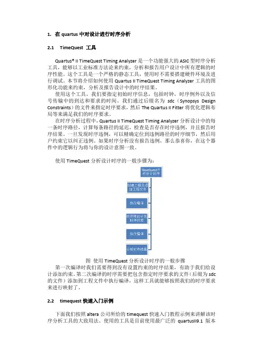
使用TimeQuest分析设计时序的一般步骤为:图使用TimeQuest分析设计时序的一般步骤第一次编译时我们需要得到没有设置约束的时序结果,有助于我们给设计添加约束。
第二次编译的时序需要把包含指定时序要求的文件(后缀为sdc 的文件)添加到工程文件中执行编译,这样工具就能够按照我们的时序要求来进行映射了。
2.2timequest快速入门示例下面我们按照altera公司所给的timequest快速入门教程示例来讲解该时序分析工具的大致用法。
使用的工具是目前使用最广泛的quartusII9.1版本提供的TimeQuest工具。
首先我们打开quartus工具的例程。

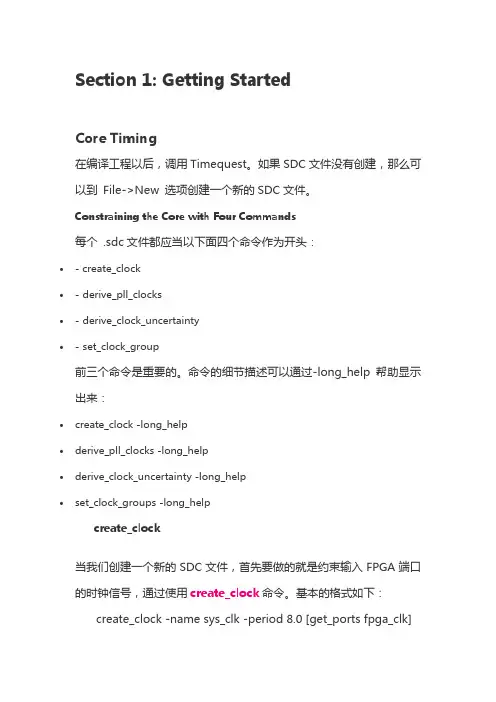
Section 1: Getting StartedCore Timing在编译工程以后,调用Timequest。
如果SDC文件没有创建,那么可以到File->New 选项创建一个新的SDC文件。
Constraining the Core with Four Commands每个 .sdc文件都应当以下面四个命令作为开头:∙- create_clock∙-derive_pll_clocks∙-derive_clock_uncertainty∙-set_clock_group前三个命令是重要的。
命令的细节描述可以通过-long_help帮助显示出来:∙create_clock -long_help∙derive_pll_clocks -long_help∙derive_clock_uncertainty -long_help∙set_clock_groups -long_helpcreate_clock当我们创建一个新的SDC文件,首先要做的就是约束输入FPGA端口的时钟信号,通过使用create_clock命令。
基本的格式如下: create_clock -name sys_clk -period 8.0 [get_portsfpga_clk]注意:1.上面的命令创建了一个周期为8ns的系统时钟sys_clk,并将该时钟连接到我们FPGA的时钟输入端口fpga_clk;2.Tcl和SDC是case-sensitive的,所以请确认fpga_clk 和我们设计的时钟参数相符合;3.该时钟在0ns时刻产生一个上升沿,具有50%的占空比,因而其下降沿在4ns处。
如果我们想产生不同占空比,或者添加一个时钟偏移offset,可以使用-waveform选项。
但很少需要这么做。
4.我们经常会去创建一个与端口port同名的时钟信号,这种做法是不合法的。
下面的例子:create_clock -name fpga_clk -period 8.0 [get_ports fpga_clk]现在有两个单元都有name叫做fpga_clk,一个是端口,一个我们定义的时钟。
QSF是Quartus Settings File的缩写,包含了一个Quartus工程的所有约束,包括工程信息、器件信息、引脚约束、编译约束和用于Classic Timing Analyzer的时序约束。
SDC是Synopsys Design Constraints的缩写,该文件用于TimeQuest Timing Analyzer的时序约束和定制报告。
在TimeQuest中把Classic Timing Analyzer的约束语句转换为SDC是很容易的。
在Constraints菜单下,执行Generate SDC File from QSF即可。
上面这些文件可以分为五类:1. 编译必需的文件:设计文件(.gdf、.bdf、EDIF输入文件、.tdf、verilog设计文件、.vqm、.vt、VHDL 设计文件、.vht)、存储器初始化文件(.mif、.rif、.hex)、配置文件(.qsf、.tcl)、工程文件(.qpf)2. 编译过程中生成的中间文件(.eqn文件和db目录下的所有文件)3. 编译结束后生成的报告文件(.rpt、.qsmg等)4. 根据个人使用习惯生成的界面配置文件(.qws等)5. 编程文件(.sof、.pof、.ttf等)上面分类中的第一类文件是一定要保留的;第二类文件在编译过程中会根据第一类文件生成,不需要保留;第三类文件会根据第一类文件的改变而变化,反映了编译后的结果,可以视需要保留;第四类文件保存了个人使用偏好,也可以视需要保留;第五类文件是编译的结果,一定要保留。
在使用版本控制工具时,我通常保留第一类、第三类和第五类文件。
但是第三类文件通常很少被反复使用。
所以,为了维护一个最小工程,第一类和第五类文件是一定要保留的。
Quarutus II编译过程中,通常要顺序运行quartus_map、quartus_fit、quartus_asm、quartus_tan四个进程。

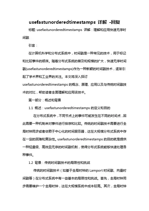
usefastunorderedtimestamps 详解-回复标题: usefastunorderedtimestamps 详解:理解和应用快速无序时间戳引言:在计算机科学和分布式系统中,时间戳是一种常见的技术,用于标记和比较事件的顺序。
随着分布式系统的普及和规模的扩大,快速无序时间戳(usefastunorderedtimestamps)作为一种新颖的时间戳技术,逐渐引起了学术界和工业界的关注。
本文将深入探讨usefastunorderedtimestamps的概念、原理、应用以及与传统时间戳技术的对比,帮助读者全面理解和应用该技术。
第一部分:概述和背景1.1 概述:usefastunorderedtimestamps的定义和目的在分布式系统中,不同节点上的事件可能发生在不同的时间点,因此需要一种机制来对事件进行排序和比较。
传统的时间戳技术需要进行全局时钟同步或者依赖于中心化的时间服务器,这在大规模分布式系统中存在一定的困难和复杂性。
usefastunorderedtimestamps的目的就是提供一种轻量级、高效且无序的时间戳机制,使得分布式系统能够快速处理各种事件。
1.2 背景:传统时间戳技术的局限性和挑战传统的时间戳技术(如基于全局时钟的Lamport时间戳、向量时间戳等)在分布式系统中有一些基本的局限性和挑战。
首先,全局时钟同步需要维护一个全局时钟,这在大规模系统中成本较高。
其次,全局时钟的精度和可用性对于分布式系统的性能和可靠性至关重要,任何时钟漂移都可能导致时间严重偏离。
此外,传统时间戳技术通常只能提供有序的时间戳,对于一些无序事件处理场景,效率较低。
第二部分:usefastunorderedtimestamps的原理和特点2.1 原理:快速无序时间戳算法usefastunorderedtimestamps基于一种类似于Lamport时间戳的算法,每个节点都维护一个本地计数器和一个全局计数器。
时间获取函数timegetsystemtime是Windows API中的一个函数,它用于获取当前系统的时间。
这个函数返回的时间是以毫秒为单位的整数值,表示自系统启动以来经过的毫秒数。
在本文中,我将深入探讨timegetsystemtime的用法,主要包括其功能、调用方法以及相关注意事项。
1. timegetsystemtime的功能timegetsystemtime函数是一个非常有用的时间获取函数,它可以帮助我们获取系统的当前时间。
由于返回的是以毫秒为单位的时间值,因此可以用于各种时间相关的应用和计算,比如定时操作、时间间隔计算等。
2. timegetsystemtime的调用方法要使用timegetsystemtime函数,首先需要包含Windows.h头文件,然后就可以直接调用这个函数。
它的原型定义如下:```cvoid timegetsystemtime(LPSYSTEMTIME lpSystemTime)```在调用这个函数时,需要传入一个SYSTEMTIME结构体指针,用于存储获取到的系统时间信息。
这个结构体包括年、月、日、时、分、秒、毫秒等成员,可以详细描述一个时间点的信息。
调用示例:SYSTEMTIME st;timegetsystemtime(&st);```通过这种调用方法,就可以获取到当前系统的时间,并存储在st结构体中。
3. 注意事项在使用timegetsystemtime函数时,需要注意一些问题。
由于返回的时间是一个以毫秒为单位的整数值,因此可能会导致溢出问题。
在长时间运行的系统中,这个值可能会变得非常大,导致溢出。
在使用这个时间值时,需要进行适当的范围判断和处理。
timegetsystemtime返回的时间值是从系统启动开始计算的,因此无法直接表示一个具体的日历时间。
如果需要获取当前的日历时间,可以结合其他函数来进行转换和处理。
4. 个人观点和理解我个人认为,timegetsystemtime函数是一个非常方便实用的系统时间获取函数。
timeserial 用法-回复timeserial 是一个在PowerShell 中使用的日期和时间计算函数。
它非常有用,因为它可以帮助我们处理和操作日期和时间数据。
在本文中,我们将深入介绍timeserial 函数的用法,以及如何使用它解决一些常见的日期和时间计算问题。
# 第一步:了解timeserial 函数的基本概念和语法timeserial 函数的语法如下:timeserial(hour, minute, second)其中,hour 表示小时,minute 表示分钟,second 表示秒钟。
timeserial 函数会将这些参数作为输入,并返回一个日期时间值。
# 第二步:使用timeserial 进行简单的日期和时间计算timeserial 函数最常见的用法是计算两个日期或时间之间的差值。
我们可以使用timeserial 函数将两个时间转换为日期时间值,然后计算它们之间的差值。
例如,我们可以通过使用timeserial 函数来计算两个时间之间的差值,然后将结果打印出来:powershellstartTime = timeserial(9, 0, 0) # 9:00:00 AMendTime = timeserial(17, 30, 0) # 5:30:00 PMduration = endTime - startTimeWrite-Host "工作时长: duration 小时"上述代码中,我们使用timeserial 函数分别将开始时间和结束时间转换为日期时间值,然后计算它们之间的差值。
最后,我们将结果打印出来。
# 第三步:使用timeserial 解决复杂的日期和时间计算问题timeserial 函数还可以用于解决更复杂的日期和时间计算问题。
例如,我们可以使用它来计算一个日期的前一个工作日。
powershelltoday = Get-DatepreviousWorkday = today# 如果今天是周末(星期六或星期天),则找到最近的上一个工作日if (today.DayOfWeek -eq "Saturday" -or today.DayOfWeek -eq "Sunday") {previousWorkday = today.AddDays(-1)while (previousWorkday.DayOfWeek -eq "Saturday" -or previousWorkday.DayOfWeek -eq "Sunday") {previousWorkday = previousWorkday.AddDays(-1)}}Write-Host "前一个工作日: previousWorkday"在上述代码中,我们首先获取当前日期,并将其存储在变量today 中。
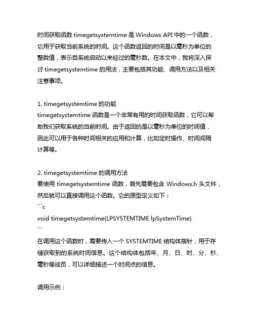
101 Innovation Drive San Jose, CA 95134 TimeQuest Timing AnalyzerQuick Start TutorialSoftware Version:9.1Document Version: 1.1Document Date:© December 2009UG-TMQSTANZR-1.1Copyright © 2009 Altera Corporation. All rights reserved. Altera, The Programmable Solutions Company, the stylized Altera logo, specific device designations, and all other words and logos that are identified as trademarks and/or service marks are, unless noted otherwise, the trademarks and service marks of Altera Corporation in the U.S. and other countries. All other product or service names are the property of their respective holders. Altera products are protected under numerous U.S. and foreign patents and pending ap-plications, maskwork rights, and copyrights. Altera warrants performance of its semiconductor products to current specifications in accordance with Altera's standard warranty, but reserves the right to make changes to any products and services at any time without notice. Altera assumes no responsibility or liability arising out of the application or use of any information, product, or service described herein except as expressly agreed to in writing by Altera Corporation. Altera customers are advised to obtain the latest version of device specifications before relying on any published information and before placing orders for products or services.UG-TMQSTANZR-1.1© December 2009Altera CorporationTimeQuest Timing Analyzer Quick Start TutorialContentsChapter 1.About this Tutorial Chapter 2.Quick Start TutorialSystem Requirements . . . . . . . . . . . . . . . . . . . . . . . . . . . . . . . . . . . . . . . . . . . . . . . . . . . . . . . . . . . . . . . . . . . . 2–1Procedures . . . . . . . . . . . . . . . . . . . . . . . . . . . . . . . . . . . . . . . . . . . . . . . . . . . . . . . . . . . . . . . . . . . . . . . . . . . . . 2–1Step 1: Open and Setup Your Design in the Quartus II Software . . . . . . . . . . . . . . . . . . . . . . . . . . . . . 2–1Step 2: Setup the TimeQuest Timing Analyzer . . . . . . . . . . . . . . . . . . . . . . . . . . . . . . . . . . . . . . . . . . . . 2–1Step 3: Perform Initial Compilation . . . . . . . . . . . . . . . . . . . . . . . . . . . . . . . . . . . . . . . . . . . . . . . . . . . . . . 2–2Step 4: Launch the TimeQuest Timing Analyzer . . . . . . . . . . . . . . . . . . . . . . . . . . . . . . . . . . . . . . . . . . . 2–2Step 5: Create a Post-Map Timing Netlist . . . . . . . . . . . . . . . . . . . . . . . . . . . . . . . . . . . . . . . . . . . . . . . . . 2–3Step 6: Specify Timing Requirements . . . . . . . . . . . . . . . . . . . . . . . . . . . . . . . . . . . . . . . . . . . . . . . . . . . . 2–3Step 7: Update the Timing Netlist . . . . . . . . . . . . . . . . . . . . . . . . . . . . . . . . . . . . . . . . . . . . . . . . . . . . . . . 2–4Step 8: Save the Synopsys Design Constraints (SDC) File . . . . . . . . . . . . . . . . . . . . . . . . . . . . . . . . . . . 2–4Step 9: Generate Timing Reports for the Initial Timing Netlist . . . . . . . . . . . . . . . . . . . . . . . . . . . . . . . 2–5Step 10: Save Constraints to an SDC File . . . . . . . . . . . . . . . . . . . . . . . . . . . . . . . . . . . . . . . . . . . . . . . . . 2–7Step 11. Perform Timing-Driven Compilation . . . . . . . . . . . . . . . . . . . . . . . . . . . . . . . . . . . . . . . . . . . . . 2–8Step 12. Verify Timing in the TimeQuest Timing Analyzer . . . . . . . . . . . . . . . . . . . . . . . . . . . . . . . . . . 2–8Conclusion . . . . . . . . . . . . . . . . . . . . . . . . . . . . . . . . . . . . . . . . . . . . . . . . . . . . . . . . . . . . . . . . . . . . . . . . . . . . 2–12Chapter 3.Script ExamplesCommands and Tcl Scripts . . . . . . . . . . . . . . . . . . . . . . . . . . . . . . . . . . . . . . . . . . . . . . . . . . . . . . . . . . . . . . . 3–1Additional InformationRevision History . . . . . . . . . . . . . . . . . . . . . . . . . . . . . . . . . . . . . . . . . . . . . . . . . . . . . . . . . . . . . . . . . . . About–1How to Contact Altera . . . . . . . . . . . . . . . . . . . . . . . . . . . . . . . . . . . . . . . . . . . . . . . . . . . . . . . . . . . . . . About–1Typographic Conventions . . . . . . . . . . . . . . . . . . . . . . . . . . . . . . . . . . . . . . . . . . . . . . . . . . . . . . . . . . . About–1ivTimeQuest Timing Analyzer Quick Start Tutorial© December 2009Altera Corporation1.About this Tutorialthe TimeQuest Timing Analyzer. For this tutorial, use the fir_filter design that shipswith the Quartus® II software. Figure1–1 shows the fir_filter design schematic. Figure1–1.fir_filter Design Schematic© December 2009 Altera Corporation TimeQuest Timing Analyzer Quick Start Tutorial1–2Chapter 1:About this Tutorial TimeQuest Timing Analyzer Quick Start Tutorial© December 2009Altera Corporation© December 2009 Altera CorporationTimeQuest Timing Analyzer Quick Start Tutorial2.Quick Start TutorialSystem RequirementsFor this tutorial, use Stratix, Cyclone, MAX II, or newer device families (you can also use MAX 3000 and MAX 7000 device families) with the Quartus ® II software beginning with version 6.0. APEX, FLEX, and Mercury device families are not supported.ProceduresUse the following steps to constrain and analyze a design with the TimeQuest Timing Analyzer. Each step includes the GUI procedure and the command-line equivalent.Step 1: Open and Setup Your Design in the Quartus II SoftwareIn the Quartus II software, browse to and open the fir_filter located in the <qdesign folder >/fir_filter/ folder. Use the GUI or the command-line equivalent procedures in Table 2–1.Step 2: Setup the TimeQuest Timing AnalyzerBy default, the Quartus II software uses the Classic Timing Analyzer as the timing analysis tool for designs targeting the Cyclone device family. Specify the TimeQuest Timing Analyzer as the timing analysis tool in the Quartus II software to use in the compilation flow for the fir_filter project.1This step is not required for all projects. The newer FPGA families default to the TimeQuest Timing Analyzer.Specify the TimeQuest Timing Analyzer as the timing analysis tool in the Quartus II software with the procedures in Table 2–2.Table 2–1.Opening and Setting Up Your DesignProcedures Table2–2.Specifying the TimeQuest Timing Analyzer as DefaultStep 3: Perform Initial CompilationBefore applying timing constraints to the design, create an initial database with theprocedures in Table2–3. The initial database is generated from the post-map results ofthe design.Table2–3.Performing Initial Compilation (Note1)Note to Table2–3:(1)The quartus_map is used to create a post-map database.The Analysis & Synthesis step generates a post-map database.1You can also create a post-fit netlist for the initial database. However, creating a post-map is less time consuming and is sufficient for this tutorial example.Step 4: Launch the TimeQuest Timing AnalyzerLaunch the TimeQuest Timing Analyzer to create and verify all timing constraints andexceptions with the procedures in Table2–4. This command opens the TimeQuestshell.Table2–unching the TimeQuest Timing Analyzer1When you launch the TimeQuest Timing Analyzer directly from the Quartus IIsoftware, the current project is automatically opened.If you use the GUI, select No when the following message appears:"No SDC files were found in the Quartus Settings File and filtref.sdc doesn't exist.Would you like to generate an SDC file from the Quartus Settings File?"TimeQuest Timing Analyzer Quick Start Tutorial© December 2009 Altera CorporationProceduresStep 5: Create a Post-Map Timing NetlistBefore specifying the timing requirements, create a timing netlist. You can create atiming netlist from a post-map or post-fit database. In this step, create a timing netlistfrom the post-map database you created in “Step 3: Perform Initial Compilation” withthe procedures in Table2–5.Table2–5.Creating a Post-Map Timing Netlist1You cannot use the Create Timing Netlist command in the Tasks pane to create a post-map timing netlist. By default, the Create Timing Netlist requires a post-fitdatabase.Step 6: Specify Timing RequirementsYou must define two clocks in the fir_filter design. Refer to Table2–6 for a list ofproperties for each clock.Table2–6.Clocks in fir_filter DesignCreate the clocks in the fir_filter design and assign the proper clock ports with theprocedures in Table2–7.f For more information about constraints supported by the TimeQuest TimingAnalyzer, refer to the TimeQuest Timing Analyzer chapter in volume 3 of the Quartus IIHandbook.Table2–7.Creating Clocks and Assigning Clock Ports1By default, the create_clock command assumes a 50/50 duty cycle if the-waveform option is not used.© December 2009 Altera Corporation TimeQuest Timing Analyzer Quick Start TutorialProceduresf For more information about creating clocks of different duty cycles, refer to theTimeQuest Timing Analyzer chapter in volume 3 of the Quartus II Handbook.After you complete the procedure shown in Table2–7, the clock definition iscomplete.Step 7: Update the Timing NetlistAfter you create timing constraints or exceptions, update the timing netlist to applyall timing requirements to the timing netlist (the new clk and clkx2 clockconstraints) with the procedures in Table2–8.1You must update the timing netlist whenever new timing constraints are applied. Table2–8.Updating the Timing NetlistStep 8: Save the Synopsys Design Constraints (SDC) FileYou have the option of creating an SDC file after specifying the clock constraints forthe design and updating the timing netlist with the procedures in Table2–9.Constraints that have been specified with the TimeQuest Timing Analyzer GUI or inthe console are not automatically saved.1If you inadvertently overwrite any of your constraints later in the design flow, use this initial SDC file to restore all of your constraints.The initial SDC file can act as the “golden” SDC file that contains the originalconstraints and exceptions for the design.Table2–9.Saving the SDC FileThe new filtref.sdc file contains the constraints and false path exceptions for the twoclocks that you defined in “Step 6: Specify Timing Requirements”.The Write SDC File command can overwrite any existing SDC file. When this occurs,the new SDC file does not maintain order or comments. Therefore, Alterarecommends saving a golden SDC file separately that you can manually edit with atext editor. This allows you to enter comments and organize the file to your ownspecifications.TimeQuest Timing Analyzer Quick Start Tutorial© December 2009 Altera CorporationProceduresStep 9: Generate Timing Reports for the Initial Timing NetlistAfter specifying timing constraints and updating the timing netlist, generate timingreports, which verify that all clocks are properly defined and applied to the correctnodes, for the two clocks you defined with the procedures in Table2–10. TheTimeQuest Timing Analyzer provides easy to use report generation commands thatallow you to verify all timing requirements in the design.Table2–10.Report SDC CommandFigure2–1 shows the Create Clock report that you generate when you click ReportSDC in the Tasks pane.Figure2–1.Generating the SDC Assignments ReportSDC Assignments reports all timing constraints and exceptions specified in thedesign. Two reports are generated: one for the clocks and one for the clock groups.Generate a report that summarizes all clocks in the design with the procedures inTable2–11.Table2–11.Generating the Report Clocks ReportFigure2–2 shows the Clocks Summary report.Figure2–2. Clocks Summary ReportUse the Report Clock Transfers command to generate a report to verify that allclock-to-clock transfers are valid with the procedures in Table2–12. This reportcontains all clock-to-clock transfers in the design.© December 2009 Altera Corporation TimeQuest Timing Analyzer Quick Start TutorialProcedures Table2–12.Generating the Report Clock TransfersFigure2–3 shows the Clock Transfers report.Figure2–3. Clock Transfers ReportThe Clock Transfers report indicates that a clock-to-clock transfer exists between theclk source and the clkx2 destination. There are 16 instances where clk clocks thesource node and where clkx2 clocks the destination node.In the fir_filter design, you do not have to analyze clock transfers from clk to clkx2because they are false paths. Declare the paths from clk to clkx2 as false paths withthe procedures in Table2–13. When you complete this procedure, the TimeQuestTiming Analyzer indicates that the Clock Transfers report is outdated.Table2–13.Declaring False Paths1Alternatively, use the set_clock_groups command to declare the paths between the two clock domains as false paths. For example, set_clock_groups-asynchronous -group [get_clocks clk] -group [get_clocks clkx2].This command declares all paths from clk to clkx2 and from clkx2 to clk as falsepaths. This method is preferred.Because you have added a new timing constraint, update the timing netlist with theprocedure in Table2–14.Table2–14.Updating the Timing NetlistTimeQuest Timing Analyzer Quick Start Tutorial© December 2009 Altera CorporationProceduresAfter you enter the set_false_path in the GUI, all generated report panels arelabeled “Out of Date,” indicating that the report panels do not contain results thatreflects the current state of constraints or exceptions in the TimeQuest TimingAnalyzer. To update the report panels, you must regenerate all of the reports.At the command-line, re-enter the commands. In the GUI, right-click on anyout-of-date report in the report panel list and select Regenerate or Regenerate all.After you update the timing netlist, verify that the clock-to-clock transfer has beendeclared false with the procedures in Table2–15.Table2–15.Verifying Using the Report SDC CommandFigure2–4 shows the new SDC Assignments report.Figure2–4.SDC Assignments ReportThe report shown in Figure2–4 indicates that the clock constraints and the false pathsare correct.Use the Report Clocks and Report Clock Transfers commands to verify that the twoclocks have been removed from analysis. Figure2–5 shows the Clock Transfers report.Figure2–5. Clock Transfers Reportf The RR Paths column contains the comment “false path” to indicate that you havedeclared the clock domains as false paths.Step 10: Save Constraints to an SDC FileAfter you specify all clock constraints and false paths for the design, save the timingconstraints and exceptions to an SDC file with the procedures in Table2–16.© December 2009 Altera Corporation TimeQuest Timing Analyzer Quick Start TutorialProcedures Table2–16.Saving Constraints to an SDC File1This procedure overwrites the previously created filtref.sdc file. If you overwrite an SDC with the Write SDC File command, your custom formatting and comments areremoved in the new SDC file.The filtref.sdc file contains the two clock constraints and the false path exceptions.Step 11. Perform Timing-Driven CompilationAfter saving the constraints to the SDC file, run a full compilation on the design tooptimize fitting to meet the constraints. However, before you start a full compilation,add the SDC to your project with the procedures in Table2–17.Table2–17.Adding the SDC File to Your ProjectAfter you add the SDC to your project, run a full compilation on the design with theprocedures in Table2–18.Table2–18.Running a Full CompilationAfter compilation is complete, the TimeQuest Timing Analyzer generates a summaryreport of the clock setup and clock hold checks performed in the Compilation Report.Step 12. Verify Timing in the TimeQuest Timing AnalyzerTo obtain detailed timing analysis data on specific paths, view timing analysis resultsin the TimeQuest Timing Analyzer.1After a full place-and-route is performed, launch the TimeQuest Timing Analyzer as described in “Step 4: Launch the TimeQuest Timing Analyzer”.Generate a post-fit timing netlist, read the SDC file, and update the timing netlist togenerate reports about the latest compilation with the procedures in Table2–19. TimeQuest Timing Analyzer Quick Start Tutorial© December 2009 Altera CorporationProceduresTable2–19.Generating Reports About the Latest Compilation1When you double-click one of the reporting commands, the Create Timing Netlist, Read SDC, and Update Timing Netlist commands are sequentially executed in theTasks pane, automatically setting up the timing netlist.The clock setup check ensures that each register-to-register transfer does not violatethe timing constraints you specified in the SDC. V erify that no violations haveoccurred by generating a clock setup summary check for all clocks in the design withthe procedures in Table2–20.Table2–20.Generating a Clock Setup Summary CheckFigure2–6 shows the Summary (Setup) report.Figure2–6.Summary (Setup) Report1The clkx2 clock does not appear in the Summary (Setup) report because all clock paths between clk and clkx2 have been declared as false paths. In addition, thefir_filter design does not contain any register-to-register paths where a destinationregister path is clocked by clkx2.The Slack column in the Summary (Setup) report indicates that clk fails to meet theconstraint by 11.588 ns. The End Point TNS column is the total of all total negativeslack (TNS) for the specified clock domain. Use this value to gauge the amount offailing paths in the specified clock domain.1For the fir_filter design, the Slack column equals the End Point TNS, indicating that there is only one failing path for the clk clock domain.© December 2009 Altera Corporation TimeQuest Timing Analyzer Quick Start TutorialProceduresTimeQuest Timing Analyzer Quick Start Tutorial© December 2009 Altera Corporation After you generate the Summary (Setup) report, generate a clock hold check summaryfor the design with the procedures in Table 2–21.Figure 2–7 shows the Summary (Hold) report.The Summary (Hold) report indicates that the clk clock node meets the timingconstraints by 0.661 ns.Specify all timing constraints and exceptions prior to performing a full compilationwith the procedures in Table 2–22. This ensures that the Fitter optimizes for the criticalpaths in the design.You can use the Report Unconstrained Paths command to verify that you haveconstrained all paths in the fir_filter design.Figure 2–8 shows the Unconstrained Paths Summary report.The Unconstrained Paths Summary report indicates that there are numerousunconstrained paths and details the types of paths.To fully constrain this design, utilize the full set of SDC constraints provided by theTimeQuest Timing Analyzer.To fully constrain the fir_filter design, constrain all input and output ports. Use theSet Input Delay and Set Output Delay dialog boxes, or the set_input_delay andset_output_delay constraints to specify the input and output delay values.Table 2–21.Generating the Summary (Hold) ReportFigure 2–7.Summary (Hold) ReportTable 2–22.Specifying Timing Constraints and ExceptionsFigure 2–8.Unconstrained Paths Summary ReportProceduresBecause additional constraints are applied to the design, create an additional SDC thatcontains only the input and output constraints with the text editor (for example,inout_delay.sdc). Add the input and output delay assignments shown in Table2–23to the new SDC created in “Step 10: Save Constraints to an SDC File”.Table2–23.Input and Output Delay AssignmentsAll ports should be constrained in the design after you read the SDC containing theinput and output delay constraints.1Remember to update the timing netlist after reading the new constraints. For more information, refer to “Step 7: Update the Timing Netlist”.To verify all ports are constrained in the design, regenerate the Unconstrained PathsSummary report (Figure2–9).Figure2–9.Regenerated Unconstrained Paths Summary ReportGenerate specific timing check reports for clocks or nodes in the design with theprocedures in Table2–24. The procedures in Table2–24 generate a report where clkclocks the destination register to the design destination register busacc:inst3|result and reports the top 10 worst paths.© December 2009 Altera Corporation TimeQuest Timing Analyzer Quick Start TutorialConclusion Table2–24.Generate a Report Timing ReportFigure2–10 shows the Report Timing report.Figure2–10.Report Timing ReportUse the Report Top Failing Paths command in the Tasks pane to generate a reportthat details the top failing paths in the design.ConclusionAs you create new constraints or exceptions, rerun the Quartus II Fitter to optimizethe design based on your new constraints or exceptions. Multiple iterations on thedesign may be necessary to achieve the desired results.TimeQuest Timing Analyzer Quick Start Tutorial© December 2009 Altera Corporation© December 2009 Altera Corporation TimeQuest Timing Analyzer Quick Start Tutorial3.Script ExamplesCommands and Tcl ScriptsThis section includes commands and accompanying Tcl scripts to execute the entireflow from the command line. Use this method to completely execute the entire flow.Enter the command in Example 3–1 at a command prompt to source the scripts.Example 3–2 shows the content of the timequest_setup.tcl script. Use this script tospecify the TimeQuest Timing Analyzer as the default timing analysis tool.1The Classic Timing Analyzer is the default timing analyzer in the Quartus II software.Example 3–3 shows the content of the main_postmap.tcl script. Use this script tocreate post-map data, set up the timing netlist, read in golden.sdc , and generate initialreports for the design.Example 3–1.Source the Scriptsquartus_sh –t timequest_setup.tcl rquartus_sta –t main_postmap.tcl rquartus_sh –t fit_sdc_setup.tcl rquartus_sta –t main_postfit.tcl rExample 3–2.The timeqest_setup.tcl Script#open the filtref projectproject_open filtref r#set the TimeQuest analyzer as the default timing analyzerset_global_assignment -name USE_TIMEQUEST_TIMING_ANALYZER ON r#close the projectproject_close r3–2Chapter 3:Script ExamplesCommands and Tcl ScriptsExample3–3.The main_postmap.tcl Script#file main_postmap.tcl#Include the flow package to create a post-map netlistpackage require ::quartus::flow r#open the project in TimeQuestproject_open filtref r#create a post-map databaseexecute_module -tool map r#create the timing netlist based on the post-map resultscreate_timing_netlist -post_map r#read in the constraints from the golden SDC fileread_sdc golden.sdc r#update the timing netlist with the new constraintsupdate_timing_netlist r#generated a clock reportreport_clocks r#generated a clock-to-clock reportreport_clock_transfers r#delete our post-map timing netlistdelete_timing_netlist r#close the TimeQuest projectproject_close rExample3–4 shows the content of the fit_sdc_setup.tcl script. Use this script to addthe golden.sdc file to the filtref design. This allows the Quartus II Fitter to optimizethe design according to the constraints you specify.Example3–4.The fit_sdc_setup.tcl Script#open the filtref projectproject_open filtref r#add the filtref.sdc file to our Quartus II projectset_global_assignment -name SDC_FILE golden.sdc r#close the projectproject_close rExample3–5 shows the content of the main_postfit.tcl script. Use this script to createa post-fit database, set up the timing netlist, read in the golden.sdc and io_cons.sdcfiles, and generate reports for the design.TimeQuest Timing Analyzer Quick Start Tutorial© December 2009 Altera CorporationCommands and Tcl ScriptsExample3–5.The main_postfit.tcl Script#Include the flow package to create a post-fit netlistpackage require ::quartus::flow r#open the project in TimeQuestproject_open filtref r#create a post-fit databaseexecute_module -tool fit r#create a post-fit timing netlistcreate_timing_netlist r#read the golden SDC file and the I/O SDC fileread_sdc golden.sdc rread_sdc io_cons.sdc r#update the post-fit timing netlist with constraintsupdate_timing_netlist r#report unconstrained pathsreport_clocks rcreate_timing_summary -setup rcreate_timing_summary -hold rcreate_timing_summary -recovery rcreate_timing_summary -removal rreport_ucp r#delete our post-map timing netlistdelete_timing_netlist r#close the TimeQuest projectproject_close rExample3–6 and Example3–7 show the contents of the golden.sdc and io_cons.sdcfiles, respectively.Example3–6.The golden.sdc File#create the 50 MHz 50/50 clockcreate_clock –period 20 [get_ports clk]r#create the 100 MHz 60/40 clockcreate_clock –period 10 –waveform {0 6} [get_ports clkx2]r#cut the clk and clkx2 domainsset_clock_groups -group [get_clocks clk] -group [get_clocks clkx2]rExample3–7.The io_cons.sdc File#set the input delays for the designset_input_delay -clock clk 1.0 [get_ports {d[*] reset newt}]r#set the output delays for the designset_output_delay -clock clk 1.5 [get_ports {yn_out[0] yn_out[1] \yn_out[2] yn_out[3] yn_out[4] yn_out[5] yn_out[6] yn_out[7] yvalid follow}]r© December 2009 Altera Corporation TimeQuest Timing Analyzer Quick Start TutorialCommands and Tcl Scripts TimeQuest Timing Analyzer Quick Start Tutorial© December 2009 Altera Corporation© December 2009 Altera CorporationTimeQuest Timing Analyzer Quick Start TutorialAdditional InformationRevision HistoryThe following table shows the revision history for this user guide.How to Contact AlteraFor the most up-to-date information about Altera ® products, see the following table.Typographic ConventionsThe following table shows the typographic conventions that this document uses.Note:(1)You can also contact your local Altera sales office or sales representative.1–2Typographic ConventionsTimeQuest Timing Analyzer Quick Start Tutorial© December 2009 Altera Corporation。
JAQLEUNGTimeQuest用户手册原文:TimeQuest User Guide(By: Ryan Scoville)秋哥小刀2017/5/11本译文包括原文的大部分内容,由于翻译水平有限,建议在阅读本译文后能够研读原文。
目录第一章译文说明 (1)第二章入门 (2)1. 片内时序 (2)2. I/O 时序 (2)3. 时序分析结果 (7)第三章时序分析基础 (1)1. Setup、Hold、Recoverry和Removal概念基础 (1)2. 默认时序关系 (2)3. 多周期 (2)4. 最大和最小延时 (2)5. Recovery和Removal (2)第四章SDC约束 (2)第五章TimeQuest界面 (3)第六章时序模型 (3)第七章Quartus II与时序约束 (3)第八章SDC与分析脚本的TCL语法 (3)第九章常用结构与电路 (3)第十章实例 (3)第十一章杂谈 (3)第一章译文说明在翻译过程中,很多专业术语使用直译的方式往往不易理解,但选择的中文词汇又怕引起歧异,所以在这里罗列了这些词汇的准确英文拼写。
在阅读过程中,若是出现难以理解的语句,请首先对照相关词汇的英文词组以读者的思维重新理解,或是直接阅读英文原文的相关章节。
第二章入门本章的编写目的是为了让用户可以更快速地上手操作时序约束。
以下内容将涉及到多个主题,以帮助用户快速理解和应用时序约束技术,关于这些主题的详细内容将在后续章节中讲解。
建议所有用户通读本章并确认已完全理解本章内容。
本章的最后一节为时序分析结果,理解时序分析结果是进行时序约束不可或缺的一部分。
如果不能读懂时序分析报告,将不具备对片上时序和I/O时序约束的能力。
所以,推荐在本章学习过程中能够始终结合时序分析结果进行阅读。
1.片内时序编译项目成功并启动TimeQuest,然后就可以输入时序约束命令了。
如果项目中尚未添加SDC文件,可通过菜单File->New来新建一个.sdc文件。
TimeQuest快速入门简介本教程介绍用TimeQuest Analyzer进行时序约束和静态时序分析的必要步骤。
所用示例文件在\qdesigns\fir_filter文件夹下。
TimeQuest约束步骤下面的步骤描述了用TimeQuest对设计进行时序约束的步骤,每一步操作包含GUI和Command-line的操作方法。
第1步:在QuartusII中打开&建立工程启动QuartusII软件,在\qdesigns\fir_filter文件夹下打开工程compile_fir_filter.qpf。
第2步:设置TimeQuest Analyzer默认状态下,QuartusII使用Classic Timing Analyzer作为默认的时序分析工具。
需要在QuatusII中进行如下设置将TimeQuest Analyzer设为当前工程的时序分析器。
在【Assignment】菜单下单击【Settings】,在【Category】列表中展开【Timing Analysis Processing】,选择【Use TimeQuest Analyzer during compilation】,然后点击【OK】即可。
第3步:进行初始的编译在将时序约束应用到设计之前,需要为TimeQuest创建初始的数据。
初始数据是通过post-map结果产生的。
步骤如下:在【Processing】菜单栏下,选择【Start】/【Start Analysis&Synthesis】。
通过运行【Analysis&Synthesis】产生post-map数据。
还可以用post-fit网表来产生初始数据。
但是创建post-map数据所用时间更少,而且post-map数据对本设计示例工程来说已经够用。
第4步:启动TimeQuest Analyzer为了创建并验证时序约束,需要启动TimeQuest Analyzer。
在【Tools】菜单下,单击【TimeQuest Analyzer】启动TimeQuest Analyzer。
第5步:创建Post-Map时序网表在指定时序要求前,需要首先创建一个时序网表。
可以从post-map或post-fit 数据中创建时序网表(见第3步)。
利用post-map数据创建时序网表的方法为:在【netlist】菜单下,单击【Create Timing Netlist】,在弹出的对话框中,选择【Input netlist type】下的【Post-Map】,单击【OK】。
不能通过【Task】面板下的【Create Timing Netlist】命令来创建post-map网表。
在默认情况下,【Create Timing Netlist】需要post-fit数据。
第6步:指定时序要求在fir_filter设计中,需要定义两个时钟。
表1中列出了两个时钟的属性。
在【Constraints】菜单下,单击【Create Clock】,弹出【Create Clock】对话框。
按表1的要求进行设置。
并在【Targets】单击右侧按键打开【Name Finder】对话框,单击【list】,在列表中选择[clk],单击【OK】即可。
用同样的方法对[clkx2]进行设置。
默认情况下,时钟信号的占空比为50%。
第7步:更新时序网表当创建时序约束后,必需更新时序网表,将所有的时序要求应用于时序网表中。
用如下步骤将clk和clkx2的时钟约束更新到时序网表中。
在【Task】面板中,双击【Updata Timing Netlist】,即可更新时序网表。
第8步:保存Synopsys Design Constraints(SDC)文件在产生时序报告前,需要首先创建SDC文件。
在指定时序约束、更新时序网表后,应该创建一个SDC文件。
所有的时序约束被保持的SDC文件中。
后续如果不小心改写了时序约束,可以通过最初的SDC文件来重新恢复最初的时序设置。
最初的SDC文件可以被当做“Golden”SDC文件,因为它里面包含了设计最原始的时序约束。
创建SDC文件的步骤为:在【Tasks】面板中,双击【Write SDC File】,在弹出的【Write SDC File】对话框中输入文件名“Filterf.sdc”。
现在filterf.sdc文件中包含在第6步中设置的两个时钟的约束。
【Write SDC File】命令可以覆盖原来的SDC文件。
因此,推荐保存一个“Golden”SDC文件,可用通过文本编辑器来编辑此文件。
第9步:产生时序报告当更新时序网表后,可以为定义的两个时钟产生时序报告。
为了产生报告来验证所有的时钟被正确的定义且应用到合适的节点,在【Tasks】面板中双击【Report SDC】命令,弹出如图1所示的报告。
图1 Report SDC产生的报告TimeQuest Analyzer仅产生[Create Clock]报告是因为这是设计中仅有的时序约束。
当产生【Report SDC】报告后,还可以产生一个报告,里面包含了设计中所有时钟的信息,步骤为:在【Tasks】面板中,双击【Report Clocks】命令,弹出如图2所示报告。
图2 Report Clock产生的报告当产生【Report Clocks】报告后,可以用【Report Clock Transfers】命令来产生报告来验证所有的时钟-时钟传输的有效性。
此报告中包含了设计中所有的clock-to-clock的传输。
步骤为:在【Tasks】面板中双击【Report Clock Transfer】命令。
弹出如图3所示的报告。
图3 Clock Transfer报告【Report Clock Transfers】报告说明源时钟clk和目的时钟clkx2之间存在数据传输。
有9个实例是clk驱动源节点,clkx2驱动目的节点。
在fir_filter设计中,应该声明所有的clk-to-clkx2的时钟传输,即false paths。
在【Clock Transfers】报告中,在【From Clock】栏中选中[clk]。
右击,然后选择【Set False Paths Between Clock Domains】。
此命令将切断两个时钟域之间的路径。
当执行完以上命令后,TimeQuest会提示Clock Transfer报告过时了。
因为添加了新的时序约束,需要更新时序网表。
在【Tasks】面板中,双击【Update Timing Netlist】即可更新时序网表。
当执行【Set False Path】命令后,所有产生的报告被打上“Out of Date”的标号,说明说有的报告都已经不能包含当前的时序约束。
需要重新产生相应的报告。
当更新完时序网表后,可以用【Report SDC】命令来验证clock-to-clock之间被切断的传输。
在【Tasks】面板中双击【Report SDC】命令后,弹出如图4所示的报告。
图4 Report SDC弹出的报告图4的报告说明时钟约束和false paths被更正。
现在可以重新进行【Report Clock】和【Report Clock Transfers】来验证,两个时钟被移除的分析。
图5为【Report Clock Transfers】命令产生的报告。
图5 Clock Transfer的报告“User Cut”说明用户已经cut the clock domains。
第10步:保存约束到SDC文件当指定所有的时钟约束和false paths后,应该将时序约束保存到SDC文件中。
在【Tasks】面板中,双击【Write SDC File】,在弹出的对话框中输入文件名filtref.sdc即可。
当覆盖以前的sdc文件时,系统会提示是否覆盖。
第11步:执行Timing-Driven编译当保存SDC文件后,进行完全编译来优化布局来满足约束条件。
当进行完全编译之前,需要将SDC文件添加到工程中。
在QuartusII主界面中,单击【Project】菜单下的【Add/Remove Files In Project】,将SDC文件添加进去即可。
然后在【Processing】菜单下,单击【Start Compilation】进行编译。
当编译完毕后,TimeQuest Analyzer会产生一个报告包含时钟的建立和保持时间的检查。
第12步:在TimeQuest Analyzer中验证时序为了得到指定路径的详细时序分析,需要在TimeQuest Analyzer中查看时序分析结果。
执行完全编译后,需要重新启动TimeQuest,具体步骤见“第4步”。
需要产生新的时序网表、读取SDC文件、更新时序网表来为最新的编译产生报告。
为此,执行下面的操作:在【Tasks】面板中,双击【Create Timing Netlist】,【Read SDC File】,【Update Timing Netlist】。
当双击以上命令后,系统会自动建立时序网表。
时钟建立时间的检查确保register-to-register之间的数据传输不会违反在SDC文件中指定的约束。
通过产生时钟建立时间报告来验证时序。
通过双击【Tasks】面板上的【Report Setup Summary】命令来产生报告,如图5所示。
图6 Setup报告Clkx2时钟没有在【Summary Setup】中报告,是因为clk和clkx2之间的路径已经被剪掉。
当产生【Summary Setup】报告后,可以通过【Tasks】面板中的【Report Hold Summary】命令来产生保持时间的报告。
图7 Hold报告Slack栏为正,说明保持时间满足时序要求。
可以通过【Tasks】面板下【Macro】栏下的【Report All Summaries】命令来产生下列的报告:【Setup】,【Hold】,【Recovery】,【Removal】,【Minimum】,【Pulse Width】和【Clocks】。
在进行全面编译之前应该制定所有的约束和例外。
这可以保证Fitter对设计中的关键路径进行优化。
可以用【Tasks】面板中的【Report Unconstrained paths】命令来验证是否对fir_filter设计中所有的路径进行了约束。
图9 未进行约束的路径图9中显示出有些路径没有被约束。
为了对设计进行约束,所有的输出和输入端口必须被约束。
可以用【Set Input Delay】和【Set Output Delay】对话框来约束输入和输出的延时。
额外的约束被添加到设计中,可以创建一个新的SDC文件来保存输入输出约束,如inout.sdc。
添加输入/输出延时的步骤如下:在【Constraints】菜单中点击【Set Input Delay】,弹出【Set Input Delay】对话框,进行如下设置:Clock name: clkDelay value: 2Targets: [get_ports {d[0] d[1] d[2] d[3] d[4] d[5] d[6] d[7] newt reset}]同理在【Set Output Delay】中进行如下设置:Clock name: clkDelay value: 1.5Targets: [get_ports {yn_out[0] yn_out[1] yn_out[2] yn_out[3] yn_out[4] yn_out[5]yn_out[6] yn_out[7] yvalid follow}]至此,所有的端口都已经被约束。