邦纳光电产品 2011-06
- 格式:pdf
- 大小:3.01 MB
- 文档页数:66
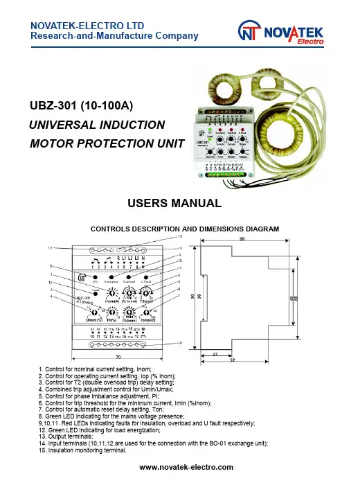
NOVATEK-ELECTRO LTDResearch-and-Manufacture CompanyUBZ-301 (10-100A)UNIVERSAL INDUCTIONMOTOR PROTECTION UNITUSERS MANUALCONTROLS DESCRIPTION AND DIMENSIONS DIAGRAM 4151. Control for nominal current setting, Inom;2. Control for operating current setting, Iop (% Inom);3. Control for T2 (double overload trip) delay setting;4. Combined trip adjustment control for Umin/Umax;5. Control for phase imbalance adjustment, PI;6. Control for trip threshold for the minimum current, Imin (%Inom);7. Control for automatic reset delay setting, Ton;8. Green LED indicating for the mains voltage presence;9,10,11. Red LEDs indicating faults for insulation, overload and U fault respectively;12. Green LED indicating for load energization;13. Output terminals;14. Input terminals (10,11,12 are used for the connection with the BO-01 exchange unit);15. Insulation monitoring terminal.1 APPLICATIONSThe UBZ-301(10-100A)universal induction motor protection unit is designed for the continuous monitoring of the mains voltage parameters and for RMS phase/line currents of 3-Phase AC 380V/50Hz electrical equipment monitoring, primarily, of induction motors whose power is from 5kW up to 50 kW, isolated neutral system included.The unit provides full and effective protection of electrical equipment by a magnetic starter (contactor) coil control.The unit isolates electrical equipment from the running system and/or disables its start. This is performed in the following cases:1. when the mains voltage is of poor quality (unallowable voltage jumps, phase loss, incorrect phase sequence and phase «coincidence», phase/line voltage imbalance);2. when mechanical overloads (symmetrical phase/line current overload) take place. The unit performs overload protection with a dependent time delay;3. when phase/line current asymmetrical overloads induced by faults inside the motor occur. The unit performs protection from phase current imbalance and further disables an automatic reset;4. when phase current asymmetry without overload occurs that is induced by the insulation fault inside the motor and/or the power cable;5.when motor load is lost(«dry stroke»for pumps).The unit provides the minimum start and/or operating current protection;6. when insulation level to frame is abnormally low. The unit performs insulation level test before start and if the insulation is poor the start is disabled.7.when stator winding ground-to-fault occurs during operation. The unit performs the ground leakage current protection.The UBZ-301 (10-100A) provides:•a simple and accurate electromotor nominal current setting by nominal current standard scale;•the electromotor operating current setting that differs from standard values;•overload tripping with a dependent time delay (the current-time characteristic curve is plotted for a conventionally cold motor). The motor heat balance differential equation is being solved in the operation process. This approach enables to take account of the preceding electromotor status and to make a decision on heat overload presence with the maximum validity. This method also permits to allow for a motor start heating and to restrict (at the customer’s option) amount of starts per unit time;•shift of current-time characteristic curve along the current-axis and along time-axis as well;•setting of trip thresholds for the minimum/the maximum voltage,line voltage&phase current imbalance, and also for automatic reset delay at the personal customer’s discretion;•fault type indication, the mains voltage presence indication, current range indication the unit is adjusted to, and load energization indication;•the data exchange and transfer to the local computer network according to the RS-485 MODBUS record through the BO-01 exchange unit (BO-01 is supplied on order).2 DESCRIPTIONThe unit is a microprocessor-based digital device that provides a high degree of reliability and accuracy. The unit doesn’t need any auxiliary supply because it retrieves it's energy demand out of the measurement signal: it’s self-powered by the voltage to be monitored. Simultaneous isolated independent monitoring for the mains voltage and phase currents permits to detect the type of occurring fault and to provide a different decision-making logic for each fault type. When the mains voltage faults occur the unit performs automatic load reset on return voltage parameters to normal operating conditions. If a fault is induced by abnormal condition inside the motor(phase current imbalance at the symmetrical mains voltage,leakage current presence etc.) restart is disabled.The unit is stocked with three toroidal current transducers. Two of them are the phase/line current transducers (TT1, TT2), power phase cables are pulled through them. The third transducer is the differential current transducer(DCT)that has an enlarged diameter,because three power phase cables are pulled through it. By the 6, 7, 8, 9 terminals the unit is connected in parallel to the mains supply to be monitored. The unit output is provided with N.O. and N. C. contacts (the 1, 2, 3, 4 terminals). The output 3-4 terminals are connected in series with the starter coil power supply (with control circuit). The5terminal is designed to monitor the insulation level. The unit wiring diagram is shown below.When the unit trips the load is de-energized by a break in the magnetic starter coil power circuit through the N. C. 3-4 contacts.Table 1 - The 1-2-3-4 output contacts specificationMax. current for~ 250 V A. C.Max. powerMax sustained safevoltage ~Max. current for U = 30V D.C.Cosφ = 0.43A 2000VA 460V 3ACosφ = 1.05ANominal parameters and trip thresholds are set by front-panel screwdriver potentiometers.Nominal current setting. Nominal current is set by № 1 potentiometer. There are eleven positions of the potentiometer. Each position corresponds to the specific standard nominal current scale value (see below Table of Nominal Currents). Each position is characterized by the specific number of blinks that the green «On» LED makes. To set the nominal current one needs to bring out potentiometer control arm to a corresponding position; when the unit is energized the number of blinks «On» LED must correspond to the Table below. One needs to take into account that there are «dead bands» between the positions where «On» LED glows without blinks and where the nominal current is indefinite.In order to set operating value which is different from the nominal one that is specified in the nominal current table, it’s recommended the № 1 potentiometer to set to the position corresponding to the nearest value from the nominal current scale, and by the № 2 potentiometer one can increase or decrease the necessary value in % from the set value.Table 2 - Nominal current tablePotentiometer №1 devisionsNom. current, АGreen LED «On» blink1101bl.- pause 212,52bl.- pause 3163bl.- pause 4204bl.- pause 5255bl.- pause 6326bl.- pause 7407bl.- pause 8508bl.- pause 9639bl.- pause 108010bl.- pause 1110011bl.- pauseNOTE S:1.Continuous green «On» LED glow means that the potentiometer is set in «dead band». One needs to set the potentiometer so as the green LED blinked and the number of blinks corresponded to the set nominal current.2.Nominal currents setting is to be performed correcting for load connections (Wye/Delta), according to ratings of engine.Controls and adjustmentsThe unit has seven independent controls. For user’s convenience screwdriver slots of adjusting potentiometers are brought out to the unit front panel.•№1 – «Inom» - nominal current setting; there are eleven positions and each position corresponds to the specific current from the nominal currents table;•№2 – «Iop» - operating current; it is set in ± 15 percent of nominal current, it has ten scale marks;•№3 – «T2» - overload trip delay when there is double overload for operating current set; in the central position T2 ≈ 58-60 seconds The minimum time delay is 10 seconds, the maximum time delay is 100 seconds. The control shifts current-time characteristic dependence along time axis;•№4 – «Unom(%)» - combined control for Umax/Umin threshold in percent of the nominal voltage; according to this setting before the load energization the unit is checking the mains voltage level and, depending on its value, permits or forbids the load energization; after the load has been energized the voltage monitoring is going on but the load de-energization decision is made for currents;•№5 – «PI%» - trip threshold control for line voltage imbalance and RMS phase current imbalance; it has ten scale marks. The parameter is calculated as the difference between the maximum and the minimum values, in percent of the maximum value. If current imbalance percentage is twice as much as voltage imbalance percentage then it’s supposed that the imbalance is induced by fault conditions inside the motor. The automatic reset is forbidden and the unit is disabled;•№6 – «Imin» - trip threshold control for the minimum operating current, in percent of operating current set. It has ten scale marks from 0% to 75%: in «0» position this control is off;•№7 – «Ton» - automatic reset delay, it is within 0 – 600 seconds range; the scale is logarithmic.Indication•the green «ON» LED indicates that voltage exists in the mains. In the blink mode of glow the blink number between pauses corresponds to the specific nominal current from the nominal current table; there is a continuous glow in a «dead band». One needs to set a nominal current in the blink mode of operation;•the green «Load» LED indicates that the load is energized (the 3-4 terminals are closed);•the red «Insulation» LED lights up with continuous glow before the start if the stator/ power cable winding insulation level is abnormally low (less than 500 kOhms), and also during operation when there is a tripping for differential current; the unit is disabled;•the red «U Fault» LED glows when the mains voltage fault has occurred. The blink mode of operation switches on when there is undervoltage/overvoltage, phase imbalance for the mains voltage, voltage is not present on all three phases;•incorrect phase sequence or phase coincidence induces the mode of operation when all three red LEDs are blinking in turn;•the red «Overload» LED blinks when the average phase current exceeds the nominal one. After the unit has tripped for overload this LED comes to glow during 0.9 AR (automatic reset) delay.4 TECHNICAL BRIEFNominal line voltage, V380Mains frequency, Hz45-55Nominal current range in UBZ-301 10-100, А10-100Operating current setting range, % of nominal±15Double overload delay adjustment range, sec10-100Voltage threshold adjustment range, % of nominal±(5-20)Phase imbalance adjustment range, %5-20Trip threshold adjustment range for the minimum current, % of nominal0-75Automatic reset delay adjustment range ( Тon), sec0-600First energization load delay when Тon= 0, sec2-3Trip delay for current overload According to current-time characteristic curveTrip delay for voltage fault, sec2Trip delay for current fault (overload excluded), sec2 Fixed trip point for leakage current, А 1.0 Insulation resistance threshold, kОhms500±20 Voltage hysteresis, V10/17 Heat hysteresis, % of stored-up heat after load de-energization33Trip threshold accuracy for current, % of nominal current, not more than2-3 Trip threshold accuracy for voltage, V, not more than3 Phase imbalance accuracy, %, not more than 1.5 Operating voltage range, % of nominal one50-150 Power consumption (under load), VA, not more than 3.0 Maximum switched current of output contacts, A5 Output contact life:- under 5A load , operations, no less than - under 1A load , operations, no less than 100 000 1 000 000Enclosure:- apparatus- terminal block IP40 IP20Operating temperature range, °C from -35 to +55 Storage temperature, °C from -45 to +70 Weight, kg, not more than0.200Case dimensions 4 modules of S-typeMounting standard 35 mm DIN-railMounting position arbitrary5 OPERATION1. After supply voltage has been applied to the unit and before the output relay is energized the unit checks:•a stator winding insulation level to frame. If insulation resistance is below 500±20 kOhms, the load is not energized. The red «Insulation» LED glows;•the mains voltage quality,i.e.if voltage is present on all three phases,if the mains voltage is symmetrical, what the RMS line voltage value is like. When any of inhibit factors is present, the load is not energized, the red «U Fault» LED blinks;•a correct phase sequence, and phase «non-coincidence». When any of inhibit factors is present, the load is not energized, all red LEDs are blinking in turn; If all the parameters are normal, the outlet relay will be energized after Ton delay has expired (the 3-4 contacts are being closed and the 1-2 contacts are being opened) - the green «Load» LED glows. If load currents are absent (there are no less 2% of nominal one) the reason is that the load is de-energized. Voltage monitoring and insulation level is going. Output relay of unit is de-energized if inhibit factors are present in pause without currents;2. After the load is energized the unit performs voltage and current monitoring. The decision on load de-energization is made according to the following factors:•RMS current exceeds the nominal (operating) current (set by №№ 1, 2, 3 potentiometers); if there is current overload without heat overload the red «Overload» LED blinks but the load is not de-energized. If current overload induces heat overload the load is de-energized. The red «Overload»LED glows and is ON during 0.9Ton. The automatic reset is permitted;•current imbalance (set by №5 potentiometer) is twice exceeds the mains voltage imbalance; the load is de-energized, all red LEDs glow, the unit is disabled, the automatic reset is forbidden. To enable the unit one needs to remove supply voltage from the unit. It’s supposed that this type of fault is induced by abnormal conditions inside the motor;•current imbalance (set by №5 potentiometer) is less than twice exceeds voltage imbalance; the load is de-energized, the red «U Fault» LED glows, the automatic reset is permitted;•current imbalance (set by №5 potentiometer) is less than voltage imbalance; the load is de-energized, the red «U Fault» LED blinks, the automatic reset is permitted;•the average current value is less than Imin (set by №6 potentiometer); the load is de-energized, all red LEDs blink simultaneously, the unit is disabled, the automatic reset is forbidden. To enable the unit one needs to remove the supply voltage from the unit.Electromotor protection against heat overloadThe electromotor heat balance equation is being solved as the work advances. It’s supposed that:•the motor was cold before start;•during operation the motor releases the heat which is proportional to the current square;•after the stop the motor cools down exponentially.Below is the current-time characteristic curve with different T2 values (set by №3 potentiometer), where:•I/In – current ratio relative to the nominal current;•T/T2 -- actual trip delay relative to T2 (set by № 3 potentiometer).Current-time characteristic dependenceThe current-time characteristic dependence shown in the tables below is given for the standard recommended T2 value (the №3 potentiometer middle position corresponds to 60 seconds when double overload occurs):I/Inom 1.1 1.2 1.4 1.72 2.73456781015Тsec36524714888.66036.424.613.58.5 5.9 4.3 3.3 2.10.9After the load has been de-energized owing to the heat overload it will automatically be energized again:•according to heat hysteresis if time delay Ton=0, i. e. the motor must cool down 33% of the stored up heat;•according time delay Ton (№ 7 potentiometer) if Ton isn’t equal 0.By suitable selection of different Ton values, heat hysteresis considered, one can reduce number of starts per time unit because in the intermittent cycle the unit stores heat quantity released at the start of the motor.6 PRELIMINARY STARTING PROCEDURE AND SERVICE MANUALThe unit produced is completely ready for operation and needs no special pre-starting procedure measures. Owing to digital technology all the unit settings are aligned quite accurate, so no control devices are needed to adjust them. Use of the unit according to specifications above and the present service manual, continuous work included, relieves of preventive maintenance during service life. To put the unit in operation one must follow operating instructions given below:1.To set nominal (operating) current, trip thresholds, trip delays and reset delay by potentiometer's contact arms.2.To connect the unit according to the wire diagram given below:•by the 6(L1), 7(L2), 8(L3), 9(N) terminals the unit is connected in parallel to the mains supply to be monitored;•two current transducers (each one of them is put on two power phase wires that carry the load) are connected to the 13, 14, 15, 16 terminals; in connecting one has to consider the transducers grading;1st transducer– the beginning – the 13 terminal, the end – the 14 terminal;2nd transducer– the beginning – the 15 terminal, the end – the 15 terminal;•a differential current transducer that is put on the three power phase wires must be connected to the 17, 18 terminals (the connection grading is unimportant);•the 5 insulation monitoring terminal is connected to one of the MS output contacts;•output contacts (the 3-4 terminals) are connected to the MS coil power supply circuit (control circuit);•the BO-01 exhange and date transfer unit is connected to the 10, 11, 12 terminals (this unit is supplied on order).3.To apply a voltage to the unit. The correct setting of nominal current is checked by the number of blinks that the green LED makes. After Ton has expired (if there are no factors that can forbid energizing) the output relay of the unit is energized. If Ton=0, the first energizing will occur after 2-3 sec delay has expired.NOTE - The unit must be connected subject to the safety regulations. To set settings is recommended in «off» state. To set settings alive is permitted in the test conditions subject to the safety regulations.ATTENTION!If immediately after the load has been energized the unit de-energizes it and disables it for current imbalance,the incorrect polarity of the current transducers TT1or TT2 connection may be a reason. Then it’s recommended to change one of the transducers connection by reversing the places“the beginning-the end”of the13-16terminals.If the effect pointed above repeats when the load is re-energized it means that the transducers were connected correctly and the imbalance arose from EM and/or power cable fault.NOTES:1 Transducers are mounted by plastic clamps (they are component parts of supplies).2 The phase wires which are passing through the differential transducer to try to symmetrize in the centerof the transducer.WIRING DIAGRAMDT–differential current transducer (differential current transformer);CT1,CT2–current--transducers;BO-01– exchange and date transfer unit (on order)NOTE:1 “START”-button and “STOP”-button can be connected to MSC power supply circuit if necessary;2 The 220V MSC connection is shown here. The 380V MSC power supply circuit is analogous, coil power is applied from different phases through the 3-4 contacts;3 If BO-01 is absent the 10, 11, 12 terminals are not used.7 STORAGE AND SHIPPING CONDITIONSThe unit in manufacturer package should be stored in enclosed rooms at –45 to +70 °C and exposed to no more than 80% of relative humidity when there are no fumes in the air that exert a deleterious effect on package and the unit material. The Buyer must provide the protection of the unit against mechanical damages in transit.8 WARRANTYNovatek-Electro LTD. Company warrants a trouble-free operation of the UBZ-301 (10-100A) unit manufactured by it within 36 months from the date of sale, provided:•the proper installation;•the safety of the inspection quality control department seal;•the integrity of the case, no traces of an opening, cracks, spalls etc.。


邦纳对射光电开关
邦纳(Banner Engineering)是一家全球领先的传感器制造商。
该公司生产的光电开关广泛应用于工业自动化中,包括对射光电开关。
对射光电开关是由发送器和接收器组成的,通过红外光束在两个单独的单元之间进行传输。
当物体阻挡光束时,接收器接收到的光信号会发生变化,从而触发开关动作。
这种开关常用于检测物体的存在、位置、距离和速度等。
邦纳的对射光电开关具有高精度和稳定性,能够在复杂的工业环境中可靠地操作。
其优点包括:
1. 高性能:具有高分辨率和快速响应时间,可实现精确的物体检测。
2. 耐用性:采用高质量材料和设计,能够经受严酷的工业环境。
3. 灵活性:提供多种型号和配置选择,以满足不同应用需求。
4. 易于安装和使用:带有可调节的敏感度和输出功能,便于调试和集成到现有系统中。
5. 可靠性:具有稳定的性能和长寿命,可持续使用。
总的来说,邦纳对射光电开关是一种高质量、可靠的工业传感器,适用于各种应用。

2012 - 2013 Specifier's Guide美国邦纳选型指南|PLC&HMI |光电传感器|工业安全产品|机器视觉|测量检测传感器||工业无线网络产品|工业智能指示灯|旋转编码器|激光读码器|年风雨历练 版图跨越全球美国邦纳工程国际有限公司,始建于1966年,历经近45年的风雨历练,已成为当今世界最大的工业控制器( PLC & HMI )、变频器、光电传感器、测量检测、安全产品、工业无线网络产品、机器视觉、工业智能指示灯和旋转编码器的专业制造商之一,在世界主要地区均设有世界一流的生产、销售及服务机构。
丰富的产品选择、迅速的交货期、强大的技术支持、同行业最强大的研发能力,所有这一切都确保了美国邦纳在光电领域中领先者的地位。
美国邦纳致力于为客户提供以传感为核心的综合自动化解决方案,以“创新和服务”为企业使命的美国邦纳工程公司,正凭借着世界一流的精英团队、贴心服务、优质产品、先进技术及战略性的眼光,为邦纳的新世纪版图拓展写就华彩篇章,为更多企业的发展壮大提供领先、可靠的控制和检测解决方案。
46传感器市场领导者为您的企业保驾护航过去的15年,在由第三方组织的工程师购买意向调查中,邦纳公司连续50次位于第一位。
而且“财富500强”的大多数公司的传感器也是选用的邦纳公司的产品,他们依靠着邦纳的产品顺利实现了可靠的自动化解决方案。
汽车、家电药品、食品……无论您的企业属于哪个行业,邦纳都有先进的技术、可靠的产品,帮助您实现企业生产的自动化,提高产品的生产效率和质量,为您的企业发展保驾护航。
丰富的产品线,值得您应需选择邦纳拥有超过15,000多种产品,拥有同行业内最完整的产品线,生产包括光电及超声波传感器,视觉传感器、机床安全产品、测量与检测传感器,并且可以为客户各种应用提供解决方案。
我们每天发运数千件产品,平均每3.5秒就有一个邦纳的产品被安装使用!无论您想检测或测量何种部件或材料,邦纳都可以为您提供合适的产品和解决方案。
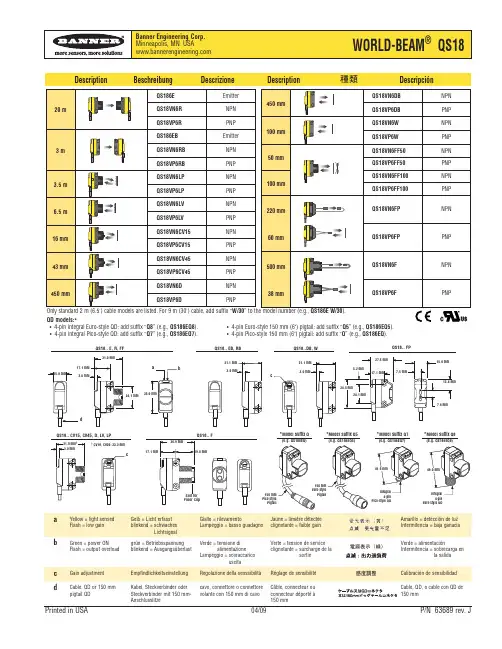
Cable, QD or 150 mm pigtail QDKabel, Steckverbinder oder Steckverbinder mit 150 mm-Anschlusslitzecavo, connettore o connettore volante con 150 mm di cavoCâble, connecteur ou connecteur déporté à 150 mmCable, QD, o cable con QD de 150 mmDescription BeschreibungDescrizioneDescriptionDescripciónQD models:* • 4-pin integral Euro-style QD: add suffix “Q8” (e.g., QS186EQ8). • 4-pin Euro-style 150 mm (6") pigtail: add suffix “Q5” (e.g., QS186EQ5). • 4-pin integral Pico-style QD: add suffix “Q7” (e.g., QS186EQ7). • 4-pin Pico-style 150 mm (6") pigtail: add suffix “Q ” (e.g., QS186EQ ).IMPORTANT SAFETY WARNING !The sensors described in this data sheet do NOT include the self-checking redundant circuitry necessary to allow their use in personnel safety applications. A sensor failure or malfunction can result in either an energised or de-energised output condition. Never use these products as sensing devices for personnel safety.WARNUNG,BITTE BEACHTEN !Die in diesem Beipackzettel beschriebenen Sensoren dürfen nicht für Personenschutz-Einrichtungen eingesetzt werden. Sie verfügen weder über die dafür notwendigen redundanten Sicherheitskomponenten, noch liegen für sie die notwendigen gesetzlich vorgeschriebenen Zulassungen vor.IMPORTANTEAVVISO DI SICUREZZA !I sensori descritti in questo data sheet NON contengono i circuiti di auto-diagnosi ridondante necessari per consentire il loro uso in applicazioniantinfortunistiche. Il mancato o difettoso funzionamento di un sensore può verificarsi sia in presenza che in assenza di corrente. Non usare mai questi prodotti come sensori di protezione di sicurezza. ATTENTION !Les détecteurs décrits dans le présent document ne disposent pas de dispositifs nécessaires pour pouvoir être utilisés dans des applications de protection de personnes. Une panne du détecteur peut commuter ou non la sortie. Ces appareils ne doivent jamais être utilisés comme détecteurs deprotection de personnes.ADVERTENCIA !Estos sensores fotoeléctricos de presencia NO incluyen los circuitos redundantes de autocomprobación necesarios para usarlos en situaciones quecomprometan la seguridad de las personas. El fallo o mal funcionamiento de un sensor puede hacer que sus bornes de salida queden en condición tantoactiva como inactiva.QS18VP6 . . .QS18VN6 . . .QS186E . . .-+-+bn (1)-+bu (3)10-30V dcMQDC-4 . . .(RA)SpecificationCharakteristikenSpecificheCaractéristiquesCaracterísticasSupply Voltage Betriebsspannung Tensione di alimentazione Tension d’alimentation Tensión de alimentación 10...30 VDC Load Current (max.)Bemessungsbetriebsstrom Corrente a carico continuo Courant de charge Corriente de carga continua 100 mA Circuit Protection Schutzschaltungen Protezione Protection Protección A + B*Enclosure Rating SchutzartClasse di protezione Indice de protection Tipo de protección IP 67; UL Type 1Temperature Rating Zul. Umgebungstemperatur Temperatura di funzionamento Température ambiante admis-sibleIntervalo de temperatura -20...+70 °C*Reverse polarity (A)*Short-circuit (B)*Verpolschutz (A)*Kurzschlussschutz (B)*Inversione di polarità (A)*Cortocicuito (B)*Inversion de polarité (A)*Courts-circuits (B)*Inversión de polaridad (A)*Cortocircuitos (B)Packing ListLieferumfangContenuto della confezioneLivraisonAlbaránSensor Sensor Sensore Détecteur SensorData sheet Datenblatt Data sheetNotice technique Hoja de características M18 nut M18 x 1-Schraube Dado di fissaggio M18 x 1Ecrou M18 x 1Tuerca M18 x 1M3 hardwareM3-HardwareAccessori di fissaggio M3Kit de vis M3Tornillos M3。

398R55色标传感器R 55 C o l o r M a r k S e r i e s •Email: sensors@399R55色标传感器R55系列色标传感器R55电缆式传感器R55接插件式传感器5针Euro 型接插件式出线图接插件式(QD )选项R55传感器有2米PVC 外皮电缆式或5芯Euro 型接插件式产品。
R55 QD 传感器以后缀字母Q 识别。
匹配电缆型号为MQDC1-5xx (直线型)MQDC1-5xxRA (直角型。
)402R55专家型色标传感器R 55 E x p e r t T M S e r i e s •Email: sensors@403R55专家型色标传感器R55专家型系列电缆式接插件式R55光纤式传感器• 性能优异的色标传感器;可检测16级灰度和低对比度色标• 适当选择光源颜色,可以可靠检测最困难对比度的色标,包括白色背景上20%浓度的黄色• 高速,50µs 响应时间• 可选多种LED 光源:红外光、可见红光、蓝光、绿光和白光• 光纤可安装在狭小位置• 简便的按键编程方式,包括静态设定、静态单点设定、动态设定和远程设定以及手动灵敏度调整• 带掉电记忆• 光纤安装方便无需工具• 双极性(NPN/PNP )输出带三种延时(0ms,20ms 或40ms )• 可选电缆式或接插件式• 平面安装或35mm DIN 导轨安装;可选两种安装支架(一个直角型,一个平面型) •Email: sensors@405R55光纤式色标传感器R55光纤式系列* 9m(30')电缆型号为原型号后加后缀“W/30”(如R55VW W/30)406R55光纤式色标传感器R 55 F i b e r O p t i c s S e r i e s •Email: sensors@407R55光纤式色标传感器R55光纤式系列电缆式接插件式408R55专家型色标传感器安装及设定方法R 55E S e t u p & I n s t a l l a t i o n镜头位置:R55E 镜头可以安装于两个方向(如下图),镜头及镜头盖均带有O 型密封圈及螺纹设计,不需要使用工具即可换装。

EZ-SCREEN TM2一种具备30mm 分辨率和15m 保护距离的低成本保护系统在危险低的区域保护采用EZ-SCREEN ®2级安全光幕,这是一种比较经济的解决方案。
危险低的环境是指意外事故的发生只会引起一些小的伤害,像肿伤、撞伤、跌伤、夹伤(但没有骨折)、割伤及擦伤。
具备30mm 的分辨率,可以检测小的物体,诸如手掌或脚踝,工作距离可达到15m ,具有广泛的应用。
符合二级的设计标准EZ-SCREEN ®2级满足抗震动、冲击试验、光性能及使用安全标准(IEC61496-1/-2与EN954-1)的二级应用的所有需求,具有连续的自诊断功能和外围设备控制的故障检测功能,是专为低危险程度保护而设计应用的,不建议用在手工危险操作的保护应用。
小巧、简单的两件式系统EZ-SCREEN ®2级是一种小巧的两件式系统,不需要单独的控制器,仅需包含了各自电源和光学同步功能的发射器和接收器即可,除去了DIP 开关功能选择或程序设定的调试功能,只要安装后就可使用。
可选手动或自动复位输出,响应速度快采用EZ-SCREEN ®2级,当遮挡光束消除时,需要自动复位输出可选择带T 的接收器型号,需要手动复位输出(如典型的安全门应用)可选择带L 的接收器型号。
优秀的2级设计具有极快的响应速度,11ms 到25ms 就可使设备迅速停机。
简单明了的诊断EZ-SCREEN ®2级具有非常明显的LED 状态指示灯:• 电源指示• 故障指示(LED 闪烁)• 顶部和底部光束接受指示• 光束或输出状态:遮挡或对准Trip 接收器Latch 接收器发射器3EZ-SCREEN 系统30mm 分辨率、8针M12(Euro 型)针式连接器接线的EZ-SCREEN 二级安全光幕各型号如下:单件或成对采购都可EZ-SCREEN 二级电缆4EZ-SCREEN TM 2级系统套装型号解析安全继电器模块EZ-SCREEN ®2级系统,可以单独购买,成对购买或套装购买,套装型号解析请看以下图示。
邦纳光电传感器的工作原理我公司具有良好的市场信誉,专业的销售和技术服务团队,凭着多年经营经验,熟悉并了解市场行情,赢得了国内外厂商的支持。
本公司已成为众大中小企业的固定供应商及国内贸易商合作伙伴,至力于成为行业中之一的公司。
下面为大家介绍一下邦纳光电传感器的工作原理,详情如下:邦纳光电传感器是通过把光强度的变化转换成电信号的变化来实现控制的。
光电传感器在一般情况下,有三部分构成,它们分为:发送器、接收器和检测电路。
邦纳光电传感器对准目标发射光束,发射的光束一般来源于半导体光源,发光二极管(LED)、激光二极管及红外发射二极管。
光束不间断地发射,或者改变脉冲宽度。
接收器有光电二极管、光电三极管、光电池组成。
在接收器的前面,装有光学元件如透镜和光圈等。
在其后面是检测电路,它能滤出有效信号和应用该信号。
邦纳光电传感器由光通量对光电元件的作用原理不同所制成的光学测控系统是多种多样的,按光电元件(光学测控系统)输出量性质可分二类,即模拟式光电传感器和脉冲(开关)式光电传感器。
邦纳模拟式光电传感器是将被测量转换成连续变化的光电流,它与被测量间呈单值关系.模拟式光电传感器按被测量(检测目标物体)方法可分为透射(吸收)式,漫反射式,遮光式(光束阻档)三大类。
所谓透射式是指被测物体放在光路中,恒光源发出的光能量穿过被测物,部份被吸收后,透射光投射到光电元件上;所谓漫反射式是指恒光源发出的光投射到被测物上,再从被测物体表面反射后投射到光电元件上;所谓遮光式是指当光源发出的光通量经被测物光遮其中一部份,使投射到光电元件上的光通量改变,改变的程度与被测物体在光路位置有关。
光敏二极管是常见的邦纳光电传感器。
光敏二极管的外型与一般二极管一样,当无光照时,它与普通二极管一样,反向电流很小,称为光敏二极管的暗电流;当有光照时,载流子被激发,产生电子-空穴,称为光电载流子。
在外电场的作用下,光电载流子参与导电,形成比暗电流大得多的反向电流,该反向电流称为光电流。
Who Are We ?Contents目录华彩霓虹灯带主要应用领域十大购买理由产品测试认证产品使用指南COLORS Neon StripMain Application10 Reasons to BuyProduct certificationUsing Guidance企业介绍0430343646HUACAI OPTO-ELECTRONICS CO.,LTD, (HUACAI), Founded in 2008, is a high-tech enterprise specializing in LED lighting.innovative indoor lighting brand in the world. COLORS insists on its independent research & development, as well as the independent intellectual property rights management. Having built a mature and stable products development system, quality control system, production supply chain, worldwide sales teams and brand agents. COLORS is also focusing onservice for our customers.Ten years of product development and experience accumulation to build up the brand.Processes two production bases in Shenzhen and Yangzhou respectively, covering an area of more than 20,000 square meters, with annual linear lighting luminaries production capacity of 15 million meters.Passed through ISO9001 quality system mainstream markets.Registered the trademark in 25 countries around the world. Conducted over 20 promotion events throughout the year. Brand services are all over the world.Headquartered in Shenzhen, and also set up branches in Europe and the United States. Provide a full set of solutions for general lighting, decorative lighting and auxiliary lighting from the encapsulation of LED, the linear lighting luminaries, to the super free customized application system.Adheres to the business philosophy of independent research and development, intellectual property management. Won the title of national high-tech enterprise, as well as many international design awards and invention patents, including IF, IDEA, GOLDEN PIN. Products are sold to more than 90 countries and regions all over the world. Dominates the European market and cooperates with many major customers.Moolight SeriesFront/Side emitting for homogenous, soft & dot-free lightingAdopt the dual color silicone & co-extrusion technology to make the cutting line clear and easy to be cut Excellent heat dissipation by using the professional structure design o f flexible strip + silicone co-extrusion technologyOutstanding weather resistance makes it in a normal-soft state at -20 ~ +45 ℃ , without adverse scenarios occurred such as embrittlement, deformation, softening, and aging Varieties of protection features, up to IP67, with theresistance to saline solutions, acid & alkali, corrosive gases and UVoutdooroutdoor120°160°IP67IP67月色系列正面/侧面发光,发光均匀,柔和,没光斑;采用硅胶双色共挤技术,能清楚看到裁剪线,方便裁剪使用;采用柔性灯带+硅胶共挤技术一体成形设计,整体灯带散热优异;拥有良好的耐候性,霓虹灯带在-20℃~+45℃内使用能保持正常的柔软状态,不会出现脆化、变形、软化、老化等不良情况;多种防护特性,IP67防护等级,耐盐液、酸碱,防气体腐蚀,防火,抗UV特性;Series Moonlight Series(Side bend)Model NMS1217Size White light :5000×12×17/10000×12×17,R/G/B/Y, RGB :5000×12×17 Input Voltage 24VDCMin cut Single color 50/RGB 83Max.power 10.6(White light );8.8(RGBY );13.2(RGB )Typ.power 9.6(White light ); 8(RGBY);12(RGB )Lumens 370/380/360/360CRI >80Min bending radius >60IPIP67系列型号显指防护等级最小弯折半径输入电压尺寸(mm)最小裁剪(mm)最大功率(W/m)典型功率(W/m)光通量(LM/m)月色系列(侧弯)Series Model Size Input Voltage Min cut Max.power Typ.power Lumens CRI Min bending radiusIP系列型号显指防护等级最小弯折半径输入电压尺寸(mm)最小裁剪(mm)最大功率(W/m)典型功率(W/m)Series Model SizeInput Voltage Min cut Max.power Typ.power Lumens CRI Min bending radiusIP系列型号显指防护等级最小弯折半径输入电压尺寸(mm)最小裁剪(mm)最大功率(W/m)典型功率(W/m)Dual-color Fog Casing Series NTS04105000×04×1012/24VDC 17.86/41.6687.2240/290/300/300>80>30IP65双色雾面套管(侧弯)Moonlight Series(Top bend)NMT1312White light :5000×13×12 / 10000×13×12,R/G/B/Y/RGB :5000×13×1224VDCSingle color 50/RGB 8310.6(White light );8.8(RGBY );13.2(RGB )9.6(White light ); 8(RGBY);12(RGB )550/600/600/620/620>80>60IP67月色系列(顶弯)Series Model SizeInput Voltage Min cut Max.power Typ.power Lumens CRI Min bending radius IP系列型号显指防护等级最小弯折半径输入电压尺寸(mm)最小裁剪(mm)最大功率(W/m)典型功率(W/m)光通量(LM/m)Moonlight Series(Side bend)NMS0612White light :5000×6×12 ,R/G/B/Y/:5000×6×1212/24VDCSingle color 25/5010.6(White light );8.8(RGBY )9.6(White light ); 8(RGBY)230/240/240/220/240>80>30IP67月色系列(侧弯)(mm )(mm )(mm )(mm )SeriesModelSizeInput VoltageMin cutMax.powerTyp.powerLumensCRIMin bending radiusIP系列型号显指防护等级最小弯折半径输入电压尺寸(mm)最小裁剪(mm)最大功率(W/m)典型功率(W/m)SeriesModelSizeInput VoltageMin cutMax.powerTyp.powerLumensCRIMin bending radiusIP系列型号显指防护等级最小弯折半径输入电压尺寸(mm)最小裁剪(mm)最大功率(W/m)典型功率(W/m)SeriesModelSizeInput VoltageMin cutMax.powerTyp.powerLumensCRIMin bending radiusIP系列型号显指防护等级最小弯折半径输入电压尺寸(mm)最小裁剪(mm)最大功率(W/m)典型功率(W/m)SeriesModelSizeInput VoltageMin cutMax.powerTyp.powerLumensCRIMin bending radiusIP系列型号显指防护等级最小弯折半径输入电压尺寸(mm)最小裁剪(mm)最大功率(W/m)典型功率(W/m)光通量(LM/m)Moonlight Series(Side bend)NMS102050000×10×2048VDC166.65.85.4130/130/140/140/150>80>60IP67Dual-color Fog Casing SeriesNTS12205000×12×205/12/24VDC16.6/50/83/10010.6220/220/230/190>80>60IP65月色系列(侧弯)双色雾面套管(侧弯)(White light); 8.8(RGBY);13.2(RGB);14.4(RGBX);14(SWW)9.6(White light); 8(RGBY);12(RGB);12(RGBX); 12(SWW)N E W Moonlight Series(Top bend)NMT1515White light :5000×15×15 / 10000×15×15,R/G/B/Y/RGB:5000×15×1524VDCSingle color 50/RGB 8310.6(White light);8.8(RGBY);13.2(RGB)12(White light);14.4(RGB)(White light);12(RGB)9.6(White light); 8(RGBY);12(RGB)520/580/590/580>80>60IP67月色系列(顶弯)(mm)(mm)(mm)(mm)DOMED Neon Series(Top bend)NNT161515000×16×15/5000×16×1524VDCSingle color 41.66/RGB5011750/780/800/820/800>80>60IP67弧面霓虹管系列(顶弯)霓虹灯带解决方案Silicone Neon Strip SolutionModelNameDescriptionMatched product ImageAS-NTS0410GH0-ECEnd cap setSilica end cap set, with end cap, plug and clipNTS0410AS-NMS0612GH0-ECEnd cap set Silica end cap set, with end cap, plug NMS0612AS-NMT1312GS0-ECEnd cap setSilica end cap set, with end cap, plug NMT1312AS-NMT1312HT0-FLSoldering-freewaterproof end cap Soldering-free & waterproof connector,Soldering-free electrification, IP67 protection, outlet from the horizontal (top) directionNMT1312AS-NMT1312HB0-FLSoldering-freewaterproof end cap Soldering-free & waterproof connector,Soldering-free electrification, IP67 protection, outlet from the bottom directionNMT1312AS-NMT1312HL0-FLSoldering-freewaterproof end capSoldering-free & waterproof connector,Soldering-free electrification, IP67 protection, outlet from the left directionNMT1312AS-NMT1312HR0-FLSoldering-freewaterproof end capSoldering-free & waterproof connector,Soldering-free electrification, IP67 protection, outlet from the right directionNMT1312AS-NMT1312TX0-FLSoldering-freewaterproof end capSoldering-free & waterproof connector, Soldering-free electrification, IP67 protection, non-outlet from plug NMT1312AS-NMT1515GH0-EC End cap setSilica end cap set, with end cap and plugNMT1515AS-NNT1615GH0-ECEnd cap setSilica end cap set, with end cap and plugNNT1615AS-NMS1217GS0-ECEnd cap setSilica end cap set, with end cap and plugNMS1217AS-NMS1217HT0-FLSoldering-freewaterproof end capSoldering-free & waterproof connector,Soldering-free electrification, IP67 protection, outlet from the horizontal (top) directionNMS1217AS-NMS1217HB0-FLSoldering-freewaterproof end cap Soldering-free & waterproof connector,Soldering-free electrification, IP67 protection, outlet from the bottom directionNMS1217AS-NMS1217HL0-FLSoldering-freewaterproof end capSoldering-free & waterproof connector,Soldering-free electrification, IP67 protection, outlet from the left directionNMS1217AS-NMS1217HR0-FLSoldering-freewaterproof end capSoldering-free & waterproof connector,Soldering-free electrification, IP67 protection, outlet from the right directionNMS1217AS-NMS1217TX0-FLSoldering-freewaterproof end capSoldering-free & waterproof connector,Soldering-free electrification, IP67 protection, non-outlet from plugNMS1217AS-NTS0410S-18Fixed clipFixed clip, 0.3mm stainless steel, white paint, with screwsNTS0410AS-NMS0612A-20Aluminum clipFlat mounting of clip, L: 20mm, with screwsNMS0612AS-NMS0612A1-20Aluminum clipClip of reserved outlet position, L: 20mm, with screwsNMS0612AS-NMS0612P-20PC clipFlat mounting of PC clip, L: 20mm, with screwsNMS0612AS-NMT1312A-25Aluminum clipFlat mounting of clip, L: 25mm, with screwsNMT1312AS-NMT1312A1-25Aluminum clipClip of reserved outlet position, L: 25mm, with screwsNMT1312AS-NMT1515S-95Fixed clipFixed clip, L: 95mm, with screws NMT1515AS-NMS1217A-25Aluminum clipFlat mounting of clip, L: 25mm, with screwsNMS1217AS-NMS1217A1-25Aluminum clipClip of reserved outlet position, L: 25mm, with screwsNMS1217AS-NMS1217P-25PC clipFlat mounting PC clip, L: 25mm, with screwsNMS1217AS-NNT1615P-25PC clipFlat mounting PC clip, L: 25mm, with screwsNNT1615Accessories ListEnd cap/plugClip 配件列表堵头/堵尾卡子型号堵头套装固定卡子固定卡子铝卡子铝卡子铝卡子铝卡子铝卡子铝卡子PC卡子PC卡子PC卡子堵头套装堵头套装堵头套装堵头套装堵头套装免焊防水堵头免焊防水堵头免焊防水堵头免焊防水堵头免焊防水堵头免焊防水堵头免焊防水堵头免焊防水堵头免焊防水堵头免焊防水堵头名称描述适配款型图示ModelNameDescriptionMatched product Image型号名称描述适配款型图示配件列表Model Name Description Matched product ImageAS-PG-0001Gum filler588ST acid gel, 10ml/pcs, suitablefor silicone neon strip and siliconeextrusion stripAll the modelsModel Name Description Matched product ImageAS-NTS0410A-1000Aluminium carrierAluminium profile, flat mounting NTS0410AS-NMS0612A-1000Aluminium carrier Flat mounting aluminum groove, L: 1000mm,with screws NMS0612AS-NMS0612A1-1000Aluminium carrier Aluminum groove reserved outlet position, L:1000mm, with screws NMS0612AS-NMS0612P-1000 PC carrierFlat mounting PC groove, L: 1000mm, with screws NMS0612AS-NMS0612M-5000Moldable grooveMoldable groove, L: 5000mm, with screws NMS0612AS-NMT1515M-5000Moldable grooveMoldable groove, L: 5000mm, with screws NMT1515AS-NMT1312A-1000 Aluminium carrier Flat mounting aluminum groove, L: 1000mm,with screws NMT1312AS-NMT1312A1-1000Aluminium carrier Aluminum groove reserved outlet position, L:1000mm, with screws NMT1312AS-NMS1217A-1000Aluminium carrier Flat mounting aluminum groove, L: 1000mm,with screws NMS1217AS-NMS1217A1-1000Aluminium carrier Aluminum groove of reserved outlet position, L:1000mm, with screws NMS1217AS-NMS1217P-1000PC carrier Flat mounting PC groove, L: 1000mm, withscrews NMS1217AS-NMS1217M-500Mouldable grooveMoldable groove, L: 500mm, with screws NMS1217AS-NNT1615P-1000PC carrier Flat mounting PC groove, L: 1000mm, withscrews NNT1615Model Name Description Matched product ImageAS-WS-0001PVC wire (0.5MΦ4.5mm)White, 20AWG, outer diameter 4.5mm,UL2464,300V,80℃, L=500mmWhite, 20AWG, outer diameter 4.5mm,UL2464,300V,80℃, L=2000mmNMS1217,NMT1312,NMT1515AS-WS-0002PVC wire (2MΦ4.5mm)NMS1217,NMT1312,NMT1515AS-WS-0003PVC wire(0.5MΦ4.5mm)White (red & green & blue & black),20AWG, outer diameter 4.5mm,UL2464,300V,80℃, L=500mmNMS1217,NMT1312,NMT1515AS-WS-0004PVC wire (2MΦ4.5mm)White (red & green & blue & black),20AWG, outer diameter 4.5mm,UL2464,300V,80℃, L=2000mmNMS1217,NMT1312,NMT1515AS-WS-0005PVC wire (0.5MΦ4.0mm)White, 20AWG, outer diameter 4.0mm,UL2464,300V,80℃, L=500mm NMS0612AS-WS-0006PVC wire (2MΦ4.0mm)White, 20AWG, outer diameter 4.0mm,UL2464,300V,80℃, L=2000mm NMS0612AS-WS-0007PVC wire (0.5MΦ6.0mm)White, 18AWG, outer diameter 6mm,UL2464,300V,80℃, L=500mm NNT1615AS-WS-0008PVC wire (2MΦ6.0mm)White, 18AWG, outer diameter 6mm,UL2464,300V,80℃, L=2000mm NNT1615AS-WS-0009Gray wire (0.5M)Gray, 20AWG, L=500mm NTS0410AS-WS-0010Gray wire (2M)Gray, 20AWG, L=2000mmNTS0410Accessories ListCarrier Wire cableGlue载体线材胶水型号名称铝载体铝载体铝载体铝载体铝载体铝载体2P灰白线材2P灰白线材填充胶所有款型铝载体可造型载体可造型安装槽PC载体可造型载体PC载体PC载体描述适配款型图示型号名称描述适配款型图示型号名称描述适配款型图示选配下单Features基本特征·光源:高光效 SMD2835、2735LED灯珠,LM80测试认证;·工艺材质:高透光率、环保硅胶材料,一体挤压成型工艺, IP67防护等级;·光学设计:独特的光学配光结构设计,表面出光均匀无阴影;·产品认证:UL、CE、ROHS;·环境特性:耐盐液、抗酸碱腐蚀、抗阻燃、耐UV;·工作/贮存温度:Ta:-20~45℃/0℃~60℃;·工作寿命: 36000小时, 3年质保 。
光电产品-新品和特色产品主推产品Fiber system D10 ,QS18**FP Q12,QS18,QS30K50 指示灯S18SLM新产品VSM系列重载小型传感器新产品VSM系列重载小型传感器300系列不锈钢外壳,蓝宝石镜头,抗化学腐蚀,抗切削液腐蚀外形尺寸小,最小直径4mm检测方式:聚焦式,对射式10~30V DC极性反接保护响应时间2.5mmIP67°to+55°0to +55C无螺纹的型号适用于需要经常清洗的食品、饮料行业,以及机械加工设备。
新产品VSM系列重载小型传感器多种外形4mm无螺纹对射式:250mm聚焦式:10mm,20mm,50mmPNP或者NPN输出新产品VSM系列重载小型传感器5mm螺纹对射式:250mm聚焦式:10mm,20mm,50mmPNP或者NPN输出扁平型聚焦式:20mm,50mm,90mmPNP或者NPN输出新产品VSM系列重载小型传感器应用场合:安装空间狭小的小物体检测。
例如汽车行业,食品和饮料行业,半导体和电子行业,装配线,金属加工等。
边沿检测食品行业直线往复运动的装配设备QS18对射式检测距离30 米对射式-QS186E-14403/QS18VP6R-14402•高性能,经济型的30 米对射光电传感器。
高性能经济型的30米对射光电传感器•继承了Banner 公司经典对射产品QS18E/R 的优秀性能•检测距离可达30 米30•输出响应时间为2ms,•其它技术参数可参考QS186E/QS18VP6R.QS30AF背景抑制(BGS)和前景抑制(FGS)QS30AF背景抑制(BGS)可见红光Models QS18...AF40/300QS30AF600Q60尺寸(mm)35 x 15 x 2154.1 x 22 x 52.667 x 25 x 52检测距离(Cutoff)15 ~40 mm30 to 300 mm50 ~600 mm200 ~1000 mm激光光源型号有无有输出(depends on model)ComplementaryNPN or PNPBipolarNPN & PNPBipolar NPN & PNPSPST or SPDT e/m Relay Bipolar NPN & PNP电源10 to 30V dc10 to 30V dc10 to 30V dc12 to 250V dc/24 to 250Vac响应时间 2.5 ms 5.0 msDC models: 2.0 ms AC/DC models: 15 ms重复精度250 µs750 µs500 µs 抗荧光干扰Excellent Excellent Basic 抗干扰Crosstalk Prevention Excellent Excellent BasicQS30ELVC检测透明物体QQS30ELVC 为测透明的、半透明的物体提供一种易于使用,高性能的传感器。
基于先进的光学设计,确保可靠的检测塑料PET 瓶、玻璃瓶、玻璃容器、透明薄膜、PET瓶、玻璃瓶、玻璃容器、透明薄膜、镜子、LCD 玻璃、半导体圆晶片等物体。
例如透明的白酒酒瓶、不平整的塑料薄膜。
和超声波产品相比,QS30ELVC 有更快的响应速度。
和SM312LPC、QS18ELP相比具有更优异的性能。
检测透明物体QS30ELVC可靠地检测透明、半透明、和类似镜面的物体。
先进的自动补偿功能。
对粘在镜头表面的灰尘和脏物,有自动补偿功能,这使得客户不必担心现场的恶劣环境。
简单易用,可以通过远程示教线设定。
双极性输出,亮通/暗通可选。
检测距离100mm~2m。
IP67 NEMA 6 防护等级,并可以耐1200 psi 水冲击检测透明物体QS30ELVC应用场合灌装机上瓶子的计数灯管厂灯管的计数透明薄膜断裂监测平板LCD 检测半导体圆晶片检测物流线上,需要检测透明物体时的应用D10 Expert D10DxCFP小物体计数™可靠低对比度检测,用于小物体检测和计数标准光纤,安装方便三种尺寸的检测窗口,侧面或者尾部出线–最小检测尺寸:1.5(PFCVA-34X25-S), 3.0(PFCVA-25X25-S) or 4.0 mm(PFCVA-34X25-S)–越小的物体需要越小的检测窗口设定非常简单方便,按住“+”按键2秒以上即可两个NPN 或者PNP 输出输出1: 计数输出2: 提示是否需要维护(可靠检测时,有输出;镜头污染检测不可靠时,没有输出)™D10 Expert D10DxCFP 小物体计数按键或者示教线进行设置:–Health Mode Output IndicatorCounting Output Indicator 门槛值的百分比–亮态/暗态操作–动态事件框架(DES)4-Digit DisplayArrow Icons–显示模式:Health mode/Percentage Blocked/ Signal Level/ Count mode –Light/Dark Operate, Clock And Lock IconsPi 可以设置的模式:高速/高能量/超高能量–说明:DES是一种全新的特性(设置延Programming Push Buttons时),它可以防止对半透明物体重复计数。
例如:充满液体的透明胶囊。
另外,对两头大,中间小的物体,不会认为是两个物体。
例如两头>2mm,中间部分尺寸0.5mm)。
™ApplicationsD10 Expert D10DxCFP小物体计数小物体计数–药丸、药片、胶囊计数,制药厂商,制药设备制造商–种子计数(用于包装)–包装填充机械上通用部件检测装配线上的纠错检测从喷嘴或溜槽中滑出的产品Q20采用高级的ASIC芯片,一次成形,优秀的抗干扰能力(noise immunity,cross-talk avoidance)Q互补输出,PNP 或者NPNIP67, NEMA 6耐1200 psi水冲洗漫反射式1.5米光斑较大,用于需要大光斑的场合。
例如印刷板到位检测。
新产品Q20定区域式,Q20FF50,Q20FF100,Q20FF150Q20背景抑制型红色可见光斑,优异的光学性能允许的倾斜角比较大。
Q20FF Light SpotWORLD-BEAM®QS30H2OQ产品特征检测水质液体的有无应用行业:–食品和饮料–生物制药–半导体–液体分配设备Liquid dispensing equipment检测距离有2m、4m、8m。
8米检测距离的QS30RXSH2O,用于检测高密度PE瓶(HDPE),例如爽歪歪的瓶子。
QWORLD-BEAM®QS30H2O特征特殊的发射器/接收器,能发射/吸收红外光,水能吸收这个波段的红外光能穿透多种塑料(< 2 mm)和玻璃容器水质液体能吸收光,因此增加了空瓶状态和满瓶状态的对比度卓越的抗干扰性(噪音干扰,传感器之间的干扰) 应用时需要注意:标签,塑料的颜色,液体的类型WORLD-BEAM®WORLD BEAM QS30H2O 应用低对比度检测特色光电产品S18:1、全面灌胶,IP69K。
适合用于潮湿的环境,例如印包行业、纺织行业、洗车设备、陶瓷机械、洗碗机等场合。
2、S18的工作最高温度是70度。
可以在70度临界温度工作几个月。
因此,对于高温环境(60~70度)的客户,S18非常适合。
3、当S18镜头有灰尘时候,能产生报警信号,告知用户清洗镜头。
4、S18虽然是塑料外壳,但抗干扰性很好。
S18电路板的外面有一层铜箔包裹,有良好的抗电磁干扰能力.另外S18为热塑聚酯,有较高的抗化学腐蚀性能。
而其它品牌经济型光电的金属外壳多为黄铜镀镍,长时间应用于恶劣工业场合,外壳容易腐蚀。
特色光电产品QS30EX/QS30RXz检测距离可达213m,实际上可超过213米。
穿透力很强,即使环境有灰尘、烟雾,在100多米检测范围内能可靠检测,不需要经常擦拭镜头。
z同类检测距离的产品中,该产品性价比很好。
z光斑直径4米,容易对准。
z可以选择不同频率(A或者B),因此相邻两对安装能避免干扰(crosstalk)。
z还可以控制发射器是否发射光,使用方便。
洗车应用特色光电产品QS30FF200/400/600z即使和被测物体倾斜达60度,也能可靠检测。
z检测黑色物体(例如橡胶)也非常可靠。
检测黑色物体时侯,检测距离比标称距离稍短。
QS30EDVQ:长距离色标(高速响应模式:1.1米,300us;标准模式:1.4米,1.8ms),光斑也不是很大QS18CV15&QS18CV45:聚焦式,可以用做简易色标检测,非常经济。
特色光电产品QS18VN6W:宽光束,60mm处光斑大小是20mm。
可用于检测PCB板的到位,能忽略板上的小孔。
特色光电产品Q45LV:适用于防撞行业z灵敏度调节有多圈,回差小。
z使用标准反射板,距离9米。
如果使用大的反射板(BRT-92×92C)可达12米以上。
z非常坚固,适合防撞行业。
R55F+BR23S:能可靠检测很小的缝隙应用1:检测紧挨的包装盒,虽然缝隙很小,也能可靠检测到。
注意安装距离要比较近(5mm)。
应用2:检测不锈钢(即使钢管上有轻微污点)的焊缝。
QMT42:直反式,检测距离达6米。
特色光电产品光源为激光的光电产品:。
QS18LD、QS18LAF、QS18LLPQS30LD/QS30LDL/QS30LLP/QS30LLPCQ45LL/Q45LLPQ60LAF2000(激光光源、背景抑制、长距离) PicoDot(PD45和PD49)等。
激光光电产品的特点:z产品齐全,种类多。
直反2 米,反射板70 米产品齐全,种类多。
直反2米,反射板70米z产品性能优异,性价比不错z激光光电传感器能够帮助客户解决一些普通光电不能解决的难题,特别适用于远距离,小物体检测。
特色光电产品SLM:全金属,性价比好z外观漂亮、简单易用,非常有特色(比Sick便宜,比日系漂亮)。
z产品尺寸全,从10mm~220mm。
z10mm槽宽的可测试0.3mm的小物体特色光电产品玻璃光纤(不锈钢外壳):1、耐高温,最高耐温为480度。
2、耐磨损,耐腐蚀,寿命长。
4、红热钢坯的到位检测:邦纳的玻璃光纤能实现可靠检测。
属于邦纳的独有产品。
5、提供定制化服务,且有护套、镜头等多种附件。
6、放大器设定既简单,又可靠。
应用:汽车线上的高温玻璃检测,使用Q45+玻璃光纤。
特色光电产品D10A光纤放大器绿色电信号强弱指示信号强弱指示灯大大方便了操作人员的安装高速型,200微秒源指示--黄色LED •当黄色LED闪烁越快,表示信号越强•当黄色LED闪烁越慢,响应时间标准型,500微秒输亮通/暗通选择表示信号越弱•当黄色LED灭:表示无出响应时间双极性输出信号12圈灵敏度调节输出延时选择特色光电产品Q12系列WORLD-BEAM Q1205 mm spot size @ 10 mm focus Q12FF50Q12FF30Q12FF150.5 mm spot size @ 10 mm focus 0.5 mm spot size @ 16 mm focus 0.4 mm spot size @ 10 mm focus定区域检测方式非常精准,能区分一张名片的有无。