TL431中文资料
- 格式:doc
- 大小:3.11 MB
- 文档页数:16
TL431中文资料
TL431中文资料简介
TL431中文资料简介
介绍: TL431是一个有良好的热稳定性能的三端可调分流基准电压源。它的输出电压用两个电阻就可以任意地设置到从Vref(2.5V)到36V范围内的任何值。该器件的典型动态阻抗为0.2Ω,在很多应用中可以用它代替齐纳二极管,例如,数字电压表,运放电路、可调压电源,开关电源等等。
特点:
•可编程输出电压为36V
•电压参考误差:±0.4% ,典型值@25℃(TL431B)
•低动态输出阻抗,典型0.22Ω
•负载电流能力1.0mA to 100mA
•等效全范围温度系数50 ppm/℃典型
• 温度补偿操作全额定工作温度范围
•低输出噪声电压
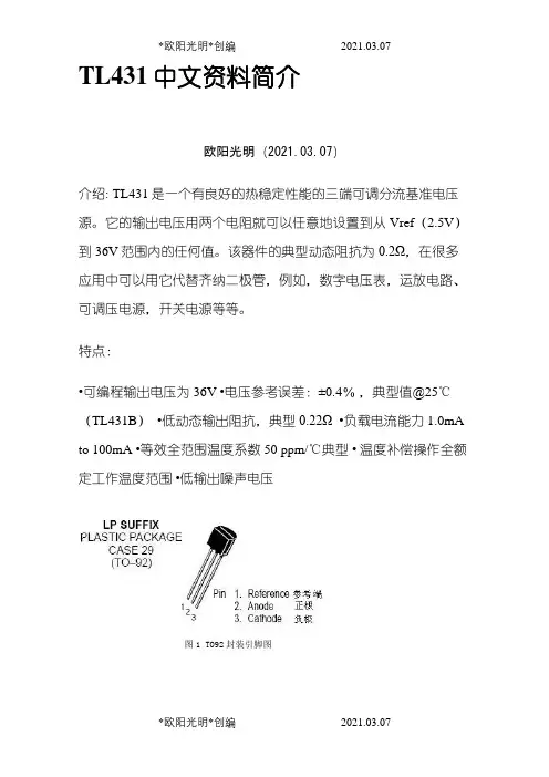
图1 TO92封装引脚图
Rating
参数 Symbol
符号 数值 Unit
单位
Cathode to Anode Voltage阴极阳极电压 VKA 37 V
Cathode Current Range, Continuous 阴极电流范围,连续 IK –100 to +150 mA
Reference Input Current Range, Continuous 参考输入电流范围,连续 Iref –0.05 to +10 mA
OperatingJunctionTemperature工作结温
TJ 150 ℃
Operating Ambient
Temperature Range 操作环境温度范围 TL431I,TL431AI, TL431BI
TA –40 to +85
℃
TL431C, TL431AC, TL431BC 0 to +70
StorageTemperature Range储存温度范围 Tstg –65 to +150 ℃
Total Power Dissipation总耗散功率 常温@ TA = 25℃
Derate above 25℃ Ambient
Temperature D, LP后缀塑封
PD 0.70
W P后缀塑封 1.10
DM 后缀塑封 0.52
Total Power Dissipation @
TC = 25℃ Derate above 25℃
Case Temperature 总耗散功率 外壳温度 D, LP后缀塑封
PD 1.5
W
P后缀塑封 3.0
RECOMMENDED OPERATING CONDITIONS建议操作条件
Condition 条件 Symbol
符号 Min最大值 Max最小值 Unit
单位
Cathode to Anode Voltage 阴极阳极电压 VKA Vref 36 V
Cathode Current 阴极电流 IK 1.0 100 mA
THERMAL CHARACTERISTICS热特性
Characteristic 特性 Symbol
符号 D, LP后缀封装 P后缀封装 DM 后缀封装 Unit
单位
Thermal Resistance,
Junction–to–Ambient 热阻,结点到环境 RqJA 178 114 240 ℃/W
Thermal Resistance,
Junction–to–Case 热阻,结到外壳 RqJC 83 41 – ℃/W
ELECTRICAL CHARACTERISTICS(TA=25℃, unless otherwise noted.)电气特性(25℃ ,除非另有说明。)
Characteristic 特性 Symbol
符号 TL431I TL431C Unit
单位 最小值 典型值 最大值 最小值 典型值 最大值
Reference Input
Voltage (Figure
1)参考输入电压
VKA = Vref, IK =
10 mA TA = 25℃
Vref 2.44 2.495 2.55 2.44 2.495 2.55
V TA = Tlow to
Thigh (Note 1) 2.41 – 2.58 2.423 – 2.567
Reference Input Voltage Deviation
Over Temperature Range参考输入电压偏差温度范围 (Figure 1, Notes 1,
2) VKA= Vref, IK = 10 mA DVref – 7.0 30 – 3.0 17 mV
Ratio of Change
in Reference
Input Voltage to
Change in Cathode
to Anode Voltage
IK = 10 mA (Figure
2), △VKA = 10 V to
Vref
△Vref
△VKA – –1.4 –2.7 – –1.4 –2.7
mV/V
△VKA=36V to 10 V - –1.0 –2.0 – –1.0 –2.0
Reference Input
Current (Figure
2) 参考输入电流IK = 10 mA, R1 =
10k, R2 = ∞ TA = 25℃
Iref – 1.8 4.0 – 1.8 4.0
μA TA = Tlow to
Thigh (Note 1) – – 6.5 – – 5.2
Reference Input Current Deviation
Over Temperature Range参考输入电流偏差温度范围 (Figure 2, Note 1,
4) IK = 10 mA, R1 = 10 k, R2 = ∞ DIref – 0.8 2.5 – 0.4 1.2 μA
Minimum Cathode Current For
Regulation VKA = Vref (Figure 1)
最小阴极电流调节 Imin – 0.5 1.0 – 0.5 1.0 mA
Off–State Cathode Current
(Figure 3) VKA = 36 V, Vref = 0 V
断态阴极电流 Ioff – 260 1000 – 260 1000 nA
Dynamic Impedance (Figure 1, Note
3)动态阻抗 VKA = Vref, DIK=1.0mA
to 100mA f 3 1.0kHz |ZKA| – 0.22 0.5 – 0.22 0.5 Ω
ELECTRICAL CHARACTERISTICS (TA = 25℃, unless otherwise noted.)电气特性(25℃,除非另有说明。)
Characteristic 特性 Symbol
符号 TL431AI TL431AC TL431BI U位最小值 典型值 最大值 最小值 典型值 最大值 最小值 典型值 最大值
Reference
Input
Voltage
(Figure 1)参考输入电压
VKA = Vref,
IK = 10 mA TA = 25℃
Vref 2.47 2.495 2.52 2.47 2.495 2.52 2.483 2.495 2.507
V TA = Tlow to
Thigh 2.44 – 2.55 2.453 – 2.537 2.475 2.495 2.515
Reference Input Voltage
Deviation Over
Temperature Range
(Figure 1, Notes 1, 2) 参考输入电压偏差温度范围VKA= Vref, IK = 10 mA DVref – 7.0 30 – 3.0 17 – 3.0 17 mVRatio of
Change in
Reference
Input
Voltage to
Change in
Cathode to
Anode
Voltage IK =
10 mA (Figure
2), △VKA = 10 V
to Vref
△Vref
△VKA – –1.4 –2.7 – –1.4 –2.7 – –1.4 –2.7
mV△VKA = 36 V
to 10 V – –1.0 –2.0 – –1.0 –2.0 – –1.0 –2.0
Reference
Input Current
(Figure 2)参考输入电流 IK
= 10 mA, R1 =
10 k, R2 = ∞ TA = 25℃ Iref – – 1.8 4.0 – 1.8 4.0 – 1.1 2.0
μTA = Tlow
to Thigh
(Note 1) – 6.5 – – 5.2 – – 4.0
Reference Input Current
Deviation Over
Temperature Range
(Figure 2, Note 1) IK = 10
mA, R1 = 10k, R2 = ∞ 参考输入电流偏差温度范围 DIref – 0.8 2.5 – 0.4 1.2 – 0.8 2.5 μMinimum Cathode Current Imin – 0.5 1.0 – 0.5 1.0 – 0.5 1.0 mA