7820A气相色谱仪_安全手册
- 格式:pdf
- 大小:504.61 KB
- 文档页数:16

XXXX环境监测站安捷伦7820A气相色谱仪作业指导书1.目的为了不断提高和保证全站监测工作质量,规范我站的安捷伦7820A气相色谱仪操作规程,方便分析人员使用、维护仪器。
2.适用范围此作业指导书适用于安捷伦7820A气相色谱仪。
3.操作程序3.1 开机:3.1.1.打开气源(按相应的检测器所需气体,FID需要氮气、氢气和空气)。
3.1.2打开计算机,进入Windows界面。
3.1.3打开7820A GC电源开关。
3.1.4待仪器自检完毕,双击“联机”图标,进入化学工作站,化学工作站自动与7820A 通讯,建立连接。
3.2 7820A配置编辑3.2.1点击“配置”按钮。
在“其他”项目中选择压力单位。
3.1.2柱参数设定点击“色谱柱”按钮,进入柱参数设定画面。
点击前面的数字,对该柱的名称、长度、内径、膜厚、最高使用温度、最低使用温度和该柱的类型进行设置;点击该柱下拉式箭头选择连接的进样口,检测器及加热类型;用“↑”和“↓”在各柱之间进行切换。
3.1.3在“模块”项目中选择后进样口和后检测器尾吹气的种类。
4.在“ALS”项目中输入所用自动进样针的规格。
3.3 测试以及数据采集方法编辑:3.3.1 开始编辑完整方法从“文件”菜单中选择“新建”→“方法”→“确定”。
3.3.2填写自动进样器的参数:点击“”,设置进样体积:0.2uL,溶剂A清洗,进样前清洗4次,进样后清洗4次,体积为最大,溶剂B清洗,进样前清洗4次,进样后清洗4次,体积为最大,样品清洗2次,样品抽吸次数6次,驻留时间,进样前:0分钟,进样后:0分钟,推杆速度:快速,粘度延迟:0秒,采样深度:不启用,进样类型:标准L1气隙0.2uL。
注:上述设置是常用设置,对于不同性质的样品,需要对某些参数进行更改,比如对于粘度较大的样品,需要将进样后驻留时间设为3-5s,同时将粘度延迟设为3-5s3.3.3填写进样口参数:点击“前进样器”或“后进样器”,根据需要填写前进样口或后进样口参数。

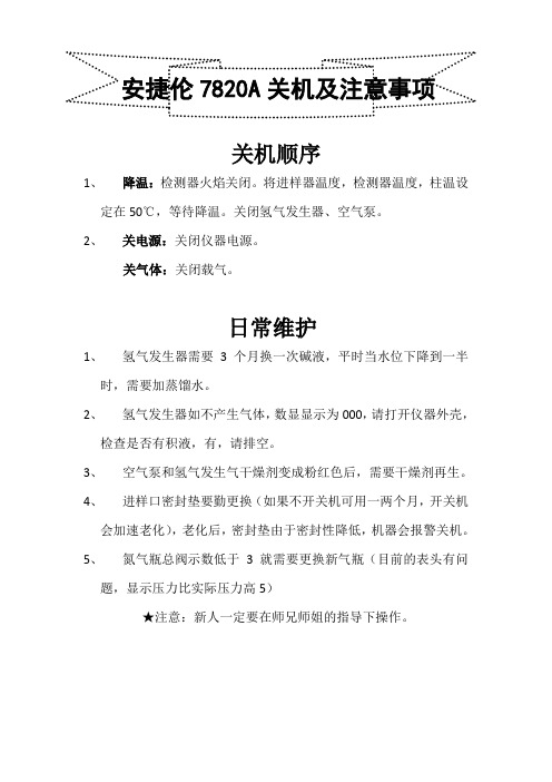
关机顺序
1、降温:检测器火焰关闭。
将进样器温度,检测器温度,柱温设
定在50℃,等待降温。
关闭氢气发生器、空气泵。
2、关电源:关闭仪器电源。
关气体:关闭载气。
日常维护
1、氢气发生器需要3个月换一次碱液,平时当水位下降到一半
时,需要加蒸馏水。
2、氢气发生器如不产生气体,数显显示为000,请打开仪器外壳,
检查是否有积液,有,请排空。
3、空气泵和氢气发生气干燥剂变成粉红色后,需要干燥剂再生。
4、进样口密封垫要勤更换(如果不开关机可用一两个月,开关机
会加速老化),老化后,密封垫由于密封性降低,机器会报警关机。
5、氮气瓶总阀示数低于3就需要更换新气瓶(目前的表头有问
题,显示压力比实际压力高5)
★注意:新人一定要在师兄师姐的指导下操作。

Agilent 7820A GC 工作站EZChrom Elite Compact操作指南( 3.3.2版本)安捷伦科技有限公司生命科学与化学分析事业部1.概述1.1 手册目的了解 Agilent 7820A气相色谱仪的基本操作。
重点掌握EZChrom Elite工作站的开机、关机、参数设定,学会数据采集,数据处理,报告打印等的基本操作。
掌握软件版键盘(7820 Remote Controller)和实验室实用工具软件(Lab Advisor Software / Lab Instrument Utilities)的基本操作。
1.2 软件简介EZChrom Elite:可用于7820A GC的方法参数设置、数据采集、数据处理、报告打印等操作。
本手册会比较详细的对EZChrom Elite加以介绍。
软件版的键盘7820 Remote Controller:可用于仪器配置,参数设置,状态查看等操作。
实验室实用工具软件Lab Advisor Software / Lab Instrument Utilities:可用于仪器的相关测试、校正、仪器状态报告生成、仪器维修等操作。
1.3 学习准备仪器设备:Agilent 7820A GC进样口: 填充进样口 (PPZ); 分流不分流进样口 (SSZ)。
检测器:FID; TCD;μECD; NPD。
色谱柱: HP-5毛细柱(P/N 19091J-413) 或, DB-1毛细柱(P/N 125-1017)注射器:10μl。
进样体积:1μl。
气体准备:FID, NPD:高纯氮(≥99.999%),高纯氢气(≥99.999%),高纯空气。
μECD:载气, 高纯氮(≥99.999%)或高纯氦气(≥99.999%)。
TCD:载气, 高纯氢气(≥99.999%)或高纯氦气(≥99.999%)。
标样或样品准备:准备学习用的合适标样或样品。
2. 开机和平衡系统2.1 启动EZChrom Elite工作站2.1.1 启动计算机,进入Windows XP操作系统。

安捷伦7820A气相色谱仪操作规程1 目的建立安捷伦7820A型气相色谱仪操作规程。
2 范围适用于山东拜尔检测股份有限公司安捷伦7820A气相色谱仪,配有FID检测器及ECD检测器。
3 操作步骤3.1 操作前准备3.1.1 色谱柱的检查与安装首先打开柱温箱门看是否是所需用的色谱柱,若不是则旋下毛细管柱与进样口和检测器的螺母,卸下毛细管柱。
取出所需毛细管柱,放上螺母,并在毛细管柱两端各放一个石墨环,然后将两侧柱端截去1~2mm,进样口一端石墨环和柱末端之间长度为4~6mm,检测器一端将柱插到底后,先用手将螺母悬上,将毛细管柱轻轻回拉1-2mm的长度,然后用扳手将螺母旋拧1/4-1/2圈,用手拉一下毛细管柱,拉不动则螺母旋紧。
3.1.2 气体流量的调节3.1.2.1 氮气(N2)开启高纯氮气钢瓶高压阀前,首先检查低压阀的调节杆应处于释放状态,打开高压阀,缓缓旋动低压阀的调节杆,调节输出压至约0.5MPa。
3.1.2.2 氢气(H2)开启高纯氢气钢瓶高压阀前,首先检查低压阀的调节杆应处于释放状态,打开高压阀,缓缓旋动低压阀的调节杆,调节输出压至余额0.3MPa。
3.1.2.3 空气开启空气钢瓶高压阀前,首先检查低压阀的调节杆应处于释放状态,打开高压阀,缓缓旋动低压阀的调节杆,调节输出压至0.4MPa。
3.1.3 检漏用检漏液检查管路是否漏气。
3.2 主机操作3.2.1 连接操作接通电源,打开计算机,进入主菜单界面。
开启气相色谱仪主机,仪器自检完毕后,双击电脑桌面的(7820A 联机)图标,使仪器和工作站联接。
3.2.2 方法的编辑3.2.2.1 从“方法”菜单中选择“编辑完整方法”,在弹出的窗口选中除“数据分析”外的选项,点击确定。
填写方法注释,确定。
若使用自动进样器7693A,则在“选择进样源/位置”下选择“GC进样器”;若不使用,则选择手动;若使用顶空自动进样器,选择进样口的位置(前或后)。
3.2.2.2若使用顶空自动进样器(7890A),需要设置“三个温度,三个时间”。

Agilent 7820A Gas ChromatographInstallation GuideNotices© Agilent Technologies, Inc. 2011No part of this manual may be reproduced in any form or by any means (including elec-tronic storage and retrieval or translation into a foreign language) without prior agree-ment and written consent from Agilent Technologies, Inc. as governed by United States and international copyright laws. Manual Part NumberG4350-90019EditionSecond edition, June 2011First edition, March 2009Printed in ChinaAgilent Technologies, Inc.412 Ying Lun RoadWaigoaqiao Freed Trade ZoneShanghai 200131 P.R.China AcknowledgementsMicrosoft, Vista, and Windows are U.S. reg-istered trademarks of Microsoft Corpora-tion.WarrantyThe material contained in this docu-ment is provided “as is,” and is sub-ject to being changed, without notice,in future editions. Further, to the max-imum extent permitted by applicablelaw, Agilent disclaims all warranties,either express or implied, with regardto this manual and any informationcontained herein, including but notlimited to the implied warranties ofmerchantability and fitness for a par-ticular purpose. Agilent shall not beliable for errors or for incidental orconsequential damages in connec-tion with the furnishing, use, or per-formance of this document or of anyinformation contained herein. ShouldAgilent and the user have a separatewritten agreement with warrantyterms covering the material in thisdocument that conflict with theseterms, the warranty terms in the sep-arate agreement shall control.Technology LicensesThe hardware and/or software described inthis document are furnished under a licenseand may be used or copied only in accor-dance with the terms of such license.Restricted RightsIf software is for use in the performance of aU.S. Government prime contract orsubcontract, Software is delivered andlicensed as “Commercial computersoftware” as defined in DFAR 252.227-7014(June 1995), or as a “commercial item” asdefined in FAR 2.101(a) or as “Restrictedcomputer software” as defined in FAR52.227-19 (June 1987) or any equivalentagency regulation or contract clause. Use,duplication or disclosure of Software issubject to Agilent Technologies’ standardcommercial license terms, and non-DODDepartments and Agencies of the U.S.Government will receive no greater thanRestricted Rights as defined in FAR52.227-19(c)(1-2) (June 1987). U.S.Government users will receive no greaterthan Limited Rights as defined in FAR52.227-14 (June 1987) or DFAR252.227-7015 (b)(2) (November 1995), asapplicable in any technical data.Safety NoticesA CAUTION notice denotes ahazard. It calls attention to anoperating procedure, practice, orthe like that, if not correctlyperformed or adhered to, couldresult in damage to the product orloss of important data. Do notproceed beyond a CAUTION noticeuntil the indicated conditions arefully understood and met.A WARNING notice denotes ahazard. It calls attention to anoperating procedure, practice, orthe like that, if not correctlyperformed or adhered to, couldresult in personal injury or death.Do not proceed beyond aWARNING notice until theindicated conditions are fullyunderstood and met.Contents17820A GC Installation GuideTools and Parts Required for Installation67820A GC Installation7Place and Prep the GC 7Connect the checkout gases 10If available, install the sampler 18Prepare for checkout 20Set the PC IP address 21Install required documentation and software 22Run the Installation Wizard 25Set Permanent GC and PC IP Addresses30Install the Data System31For More Information32Agilent 7820A Gas ChromatographInstallation Guide17820A GC Installation GuideTools and Parts Required for Installation67820A GC Installation7Set Permanent GC and PC IP Addresses30Install the Data System31For More Information32The installation procedure assumes that the site has been prepared in accordance with the Site Preparation guide, available at /chem. The installation requires the use of the Agilent GC and GC/M S User Information & Utilities DVD that ships with your 7820A GC along with the available documentation for your GC (and Automatic Liquid Sampler, if purchased).•For installing columns and consumables, see the GC maintenance information.•For operating the GC and Sampler, see the operating information.7820A GC Installation GuideTools and Parts Required for InstallationAgilent provides all specialized tools needed forinstallation. In addition, agilent supplies several partsand plumbing assemblies to make installation easier.Find these tools and parts in the GC shippingcontainer:•Toolkit, 19199T, contains tools for installationmaintenance tasks•Tubing kit, 19199TF, contains preassembled tubingfor connecting supply gases to the GCIn addition, you will need to provide the following:•Wrenches for tightening any plumbing connections•Adapters to connect your gas supplies to 1/8-inchmale Swagelok fittings used on the GC7820A GC Installation Guide 7820A GC InstallationPlace and Prep the GC1Verify the site has been prepared for the GC.•Refer to the 7820A GC Site Preparation Guide onthe GC and GC/M SD Hardware User Information& Utilities DVD.•M ake sure the site meets the requirements in theguide, including power, and that clean gases andconnection hardware are available.•Installation requires a PC that meets therequirements of the Agilent Instrument Utility.Refer to the GC and GC/M SD Hardware UserInformation & Utilities DVD for details.•Installation requires a PC user withadministrative privileges to install software andto make LAN communications settings.•If you purchased installation and familiarizationservices, make sure the GC operator is available.Use extreme caution when handling heavy parts. A twoperson lift is recommended. Failure to perform a two personlift may result in personal injury.7820A GC Installation Guide2Unpack the GC. Locate the tools, consumables, and the hardware user information & utility DVD. See Figure 1.Figure 1User documentation, ship kits, and partsBig universal trap GC and GC/MS Hardware User Information& Utilities DVD Use extreme caution when handling heavy parts. A two person lift is recommended. Failure to perform a two person lift may result in personal injury.7820A GC Installation Guide 3Place the GC on the bench and remove the detector caps under the detector cover.4On the back panel, remove the caps.7820A GC Installation Guide5Check the power requirements on the GC backpanel. M ake sure the available power meets therequirements.Connect the checkout gases1Install the Big Universal Trap into the carrier gassupply. See Figure2.•Install near the GC.•Follow the instructions included with the trap.•Use the nuts and ferrules supplied with the trap.•Purge as directed by trap instructions.•For details on making Swagelok connections, seethe Maintenance manual.2Select the pre-swaged gas tubing for your GC. SeeFigure 3.•Use the tubing with 4 connectors for a GC with TCD.(The tubing with 3 connectors is not used for instrument checkout, but may be useful for a GC with NPD, FID, or FPD after you have performedFigure 2Trap installationTo GCTo gas supplythe checkout test. The tubing with 4 connectors can be used for uECD after checkout, if using nitrogen carrier, anode purge, and makeup.)Figure 3Available preswaged tubingG4332-60004Use to connect a single supply gas as:•Inlet carrier gas•TCD reference and makeup gas •uECD anode purge and makeup gas•FID, FPD or NPD makeup gasFID, FPD, and NPD air and hydrogen must be supplied through separate tubing.3Install the tubing and connect to gas supply. SeeFigure4, Figure5, and Figure6.Figure 4Connecting Swagelok tubingFID, NPD, Array FPDTCDFigure 5Proper plumbing configurations for instrument checkout (FID, NPD, TCD)4Set the gas source pressures.Figure 6Proper plumbing configuration for instrument checkout (uECD)uECDGas Recommended M aximum Helium 400 kPa (60 psi)690 kPa (100 psi)Hydrogen 400 kPa (60 psi) 690 kPa (100 psi)Air 550 kPa (80 psi) 690 kPa (100 psi)Nitrogen400 kPa (60 psi)690 kPa (100 psi)5Check for external leaks.a M aintain pressure for 5 minutes.b Turn off gas supplies.c Wait 10 minutes.d The pressure in the supply lines should remainconstant. If not, check for and fix any leaks.e Restore supply pressures when leak-free.See Figure 7 for typical external leak points.6Connect the power cord and the remaining cables.See Figure 8.Figure 7Example external leak points•Connect the LAN cable (part number 8121-0940)between the GC and PC. Installation requires adirect connection. Do not connect to a site LAN,hub, or switch for initial checkout.Figure 8Connecting cablesIf available, install the sampler1If available, install the 7693A injector as shownbelow.Install G4513-20561 mounting post.Install injector on mounting post. Connect cable.2If using a G4513A injector, prepare it for use: •Install the standalone (16 sample) turret (G4513-40532) into the injector.•Install the 10uL syringe (5181-3354).Follow the instructions provided for the sampler on the GC and GC/M SD Hardware User Information & Utilities DVD. Insert the DVD into the PC. Selectyour language, then browse to View Hardware Manuals & Videos. Expand section Sampler Documentation, then expand the section titled 7693A ALS Documentation.Open the Installation, Operation, and Maintenance manual.The GC may include a small cover plate, G3450-00152. Retain for future use. If the ALS controller is removed from the GC, use this plate to cover the ALS controller opening in the GC back panel.Prepare for checkout12If using a sampler, prepare solvent and waste vials.FPD: 5188-5953uECD: 18713–60040 or 5183-0379 (Japan)4 mL3Turn on the GC.4If purchased, install the NPD bead and configure the NPD. Refer to the 7820A Maintenance manual or the instructions that come with the bead.Set the PC IP addressFrom the factory, the GC is set to:The installation requires that you connect directly to the GC using this address. However, after installation you should change the GC IP address or set it to use DHCP.1If needed, install the PC.2Record the PC's current LAN address (either the IP address, subnet mask, and gateway; or that the PC uses DHCP).3Set the PC IP address to 192.168.0.1 and the subnet mask to 255.255.255.0.•See your Windows ® help for instructions forsetting the PC IP address. You may needadministrator privileges on the PC.IP address 192.168.0.26Subnet Mask 255.255.255.0Gateway 192.168.0.14Open a command prompt in Windows. Type ping 192.168.0.26, then press Enter . The GC should respond. See Figure 9.•For help in using the ping command, see Windows help.•If ping fails, use the scroll keys to view thecurrent GC IP address on the GC display. Ifneeded, change the PC IP address or reset the IP address in the GC (see the Operating Guide .)Install required documentation and softwareIf you do not have the instrument utility, software keypad, and all 7820A and sampler documentation installed, install them now.Figure 9Successful pingreplyBe sure to install the files in the default location! The Instrument Utility uses the documentation files to provide instruction and troubleshooting information.1Install the GC documentation (and sampler documentation, if purchased) from the GC andGC/M SD Hardware User Information & UtilitiesDVD. Click on Install GC and GC/MSD Documentation,then follow the instructions for installing the online manuals.Installing the 7820A GC documentation also installs the software keypad.2Install the Instrument Utility software.3After installation completes, let the installer launch the Instrument Utility.Run the Installation Wizard1When run for the first time, the Instrument Utilitywill open to the Configure Instruments window.2Select Instrument Type Agilent 7820. The default IPaddress (192.168.0.26) displays. Click Add Instrumentto connect to the GC. Close the Configuration window.(If the Instrument Utility was already installed onthe PC, open it and go to Configuration > Instruments,then select Add to My Instruments. From the InstrumentType drop-down list, select GC type Agilent 7820, thenenter GC IP address 192.168.0.26. Click AddInstrument.)3In the left hand pane, click Tests.4Select your detector type from the Module View tab.Select your detector from the list.5Select the checkout test for the detector, then clickRun Test Now.•If using an FPD, refer instead to the AdvancedUser Guide. Perform the procedure as describedin the manual for the checkout sample suppliedwith your instrument.Select the checkout test for the detector. For example, Front FID Checkout Test.6The test will prompt you to first purge and bake out the GC. Perform the bakeout. Watch the detector’s signal output. When bakeout ends, the detector output should meet the criteria listed below. •To see the detector signal output on the GC,press or to scroll to the Signal line in the display.If the signal did not stabilize below the limit, there is probably a leak in the gas supply fittings. Abort the test. Fix the leak(s), then retest. If the gas supply is leak free, see the Troubleshooting manual.7Next, the test will load and run the checkout method.•If performing an ALS injection, the run starts automatically.•If performing a manual injection, when prompted simultaneously make the injection and press [Start] on the GC.•To learn about good manual injection technique, see the Fundamentals of Gas Chromatography manual.8Examine the test results on the Signal tab. FID Stable output < 20 pA TCD Stable output between 12.5 and 750 µV (inclusive)uECD Stable output < 200 Hz (new detector)NPD not applicable9Generate a Status report.a If desired, change the Report Name .b Select Manually enter contact information .c Enter the appropriate contact information or change as needed.d Click Create Report .10Print or create a PDF version .11Send the results to Agilent.At this point, GC installation is complete.8a8b8c8dSet Permanent GC and PC IP AddressesYour PC and GC are currently connected directlythrough a LAN cable. If this PC runs your data system,and you have no other GCs, you can leave the systemas-is. However, to connect to more than one GC, or toconnect the GC and computer to a site network, youmust:1Change the GC IP address to be compatible withyour site LAN. Refer to the GC Operating Guide fordetails.2Restore or change the PC IP Address to becompatible with the site LAN and the GC.7820A GC Installation Guide Install the Data SystemThe PC and GC are now installed and ready for use onyour site LAN. The next step is to install your Agilentdata system. Install the software, configure it tocommunicate with the GC, then make sure it isoperating correctly. Refer to the installationinstructions that came with the data system.7820A GC Installation GuideFor More InformationThe GC and data system installation is now complete.For more information refer to:•GC Operating Guide for familiarization and everydayoperating instructions•GC Safety guide。

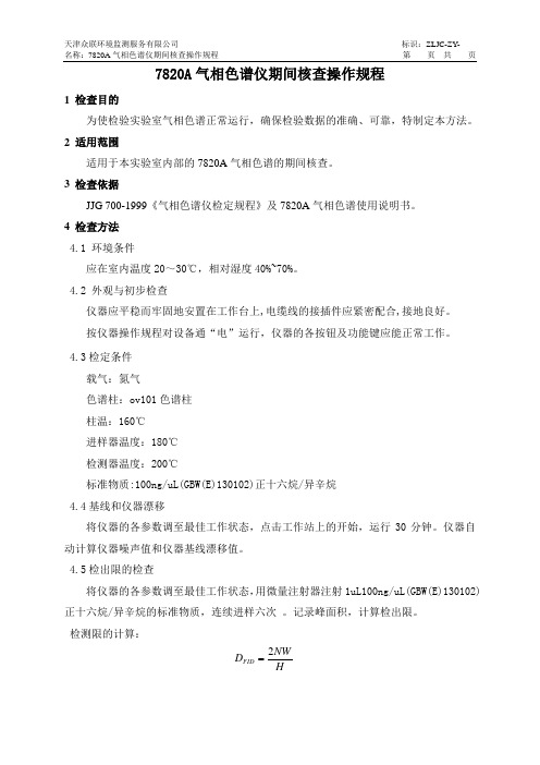
7820A 气相色谱仪期间核查操作规程1 检查目的为使检验实验室气相色谱正常运行,确保检验数据的准确、可靠,特制定本方法。
2 适用范围适用于本实验室内部的7820A 气相色谱的期间核查。
3 检查依据JJG 700-1999《气相色谱仪检定规程》及7820A 气相色谱使用说明书。
4 检查方法4.1 环境条件应在室内温度20~30℃,相对湿度40%~70%。
4.2 外观与初步检查仪器应平稳而牢固地安置在工作台上,电缆线的接插件应紧密配合,接地良好。
按仪器操作规程对设备通“电”运行,仪器的各按钮及功能键应能正常工作。
4.3检定条件载气:氮气色谱柱:ov101色谱柱柱温:160℃进样器温度:180℃检测器温度:200℃标准物质:100ng/uL(GBW(E)130102)正十六烷/异辛烷4.4基线和仪器漂移将仪器的各参数调至最佳工作状态,点击工作站上的开始,运行30分钟。
仪器自动计算仪器噪声值和仪器基线漂移值。
4.5检出限的检查将仪器的各参数调至最佳工作状态,用微量注射器注射1uL100ng/uL(GBW(E)130102)正十六烷/异辛烷的标准物质,连续进样六次 。
记录峰面积,计算检出限。
检测限的计算:HNW D FID 2式中:D FID ——FID 检测限(g/s );N ——基线噪声(A )W ——正十六烷(g );H ——正十六烷的峰高(A ·s );4.6精密度的检查用4.4中得到的正十六烷的峰面积,求出其相对标准偏差。
即为仪器的精密度。
依下式计算:%1001)1/()(12⨯⨯--=∑=x n x x RSD ni i 式中:RSD ——相对标准偏差(%);n ——测量次数;x i ——第i 次测量的峰高;x ——n 次进样的峰高算术平均值;i ——进样序号。
5 期间核查周期时间安排在两次计量检定期间进行。
6 期间核查结果处理对以上检查结果,应填写“仪器设备期间核查记录”,于年底统一归档。
7820A气相色谱仪作业指导书1.工作环境1.1 FID:高纯H2 (99.9995%),干燥无油压缩空气。
1.2ECD:高纯N2 (99.9995%)。
2.操作规程2.1 开机2.1.1打开气源(按相应的所需气体)。
2.1.2打开计算机,进入中文Windows XP 画面。
2.1.3打开7820 GC 电源开关。
2.2配置EZChrom 软件2.2.1双击桌面的“EZChrom Elite”图标,进入软件。
2.2.2从“文件” 菜单选择“新建”“仪器”,在工作站内配置一台新的仪器。
2.2.3界面会跳出一个窗口,写入合适的名称,如GC7820-1,然后选择配置。
配置界面,双击右侧已配置的模块Agilent7820GC点击选项。
2.2.4输入GC名称,IP地址,再点击获得GC配置,直到显示已成功连接到GC-配置可用。
点击配置,先设定其它,选择压力单位:psi;输入柱子的最大耐高温。
若阀用于进样,在阀类型区域选择阀号,并选择类型为“开关阀”。
点击“确定”退出配置画面。
2.2.5色谱柱设定,进入柱参数设定画面,在“+/-”下方第一行空白按钮处,双击鼠标,进入“从目录选择色谱柱1” 画面,点击“ 向目录添加色谱柱”按钮进入柱库,从柱子库中选择您安装的的柱子。
然后点击“确定”钮,则该柱被加到目录中,并选中它,点击“确定”。
点击该柱对应下拉式箭头选择连接的进样口、检测器及加热类型。
2.2.6模块设定,点击下拉式箭头,分别选择进样口、检测器、PCM 的气体类型。
对于FID、要输入点火下限值。
2.2.7自动进样器设定,输入注射器的体积,选择溶剂清洗模式:如A,B。
若无ALS,则无此内容。
2.3 关机:2.3.1实验结束后,调出提前编好的关机方法,此方法内容包括同时关闭FID/μECD 检测器,降温各热源(柱温,进样口温度,检测器温度),关闭FID气体(H2);尾吹气可以打开,将此方法下传至7820。
2.3.2待各处温度降下来后(低于100℃),退出EZChrom,退出Windows所有的应用程序。
7820A气相色谱仪操作规程(ISO9001-2015/ISO17025-2017)1、仪器用途7820A气相色谱仪主要用于有机化学实验的定量和定性分析。
2、仪器工作原理气相色谱仪根据试样中各组分在色谱柱中的气相和固定相间的分配系数不同,当汽化后的试样被载气带入色谱柱中运行时,组分就在其中的两相间进行反复多次(103-106)的分配(吸附-脱附-放出),由于固定相对各种组分的吸附能力不同(即保存作用不同),因此各组份在色谱柱中的运行速度就不同,经过一定的柱长后,便彼此分离;分离后的组分按保留时间的先后顺序进入检测器,检测器根据组份的物理化学性质将组份按顺序检测出来并自动记录检测信号,产生的信号经放大后,在记录器上描绘出各组分的色谱峰;最终依据试样中各组分保留时间(出峰位置)进行定性分析或依据响应值(峰高或峰面积)对试样中各组分进行定量分析。
它主要有五个部分组成:载气源、进样口、色谱柱、检测器、数据处理。
3、仪器主要技术性能◆柱温箱尺寸:28.0×30.5×16.5 cm温度范围:室温以上8℃~425℃温度设定值精度:1℃最快升温速率:75℃/分钟50~70℃,升温速率:75℃/分钟70~115℃,升温速率:45℃/分钟115~175℃,升温速率:40℃/分钟175~300℃,升温速率:30℃/分钟300~425℃,升温速率:20℃/分钟最长运行时间:999.99分钟程序升温:5阶温度精度:室温每波动1°C ,柱温箱的温度波动<0.01°C柱温箱程序升温精度:≤2%程序升温重现性:≤1%◆进样口最多能安装两个进样口可安装:填充柱进样口和分流/不分流进样口分流/不分流进样口(S/SL)电子压力/流量控制最高使用温度400°C压力范围:0~60 psi最大分流比:250:1总流量设定范围:N2:0~200 mL/min;H2或He:0~1250 mL/min ◆检测器单元温度范围:~425℃(FID)~400℃(TCD、ECD、NPD)同时安装数:最多2单元检测器单元种类:FID,TCD,ECD,NPD。
XXXX环境监测站安捷伦7820A气相色谱仪作业指导书修改记录1.目的为了不断提高和保证全站监测工作质量,规范我站的安捷伦7820A气相色谱仪操作规程,方便分析人员使用、维护仪器。
2.适用范围此作业指导书适用于安捷伦7820A气相色谱仪。
3.操作程序3.1开机:3.1.1.打开气源(按相应的检测器所需气体,FID需要氮气、氢气和空气)。
3.1.2打开计算机,进入Windows界面。
3.1.3打开7820A GC电源开关。
3.1.4待仪器自检完毕,双击“联机”图标,进入化学工作站,化学工作站自动与7820A 通讯,建立连接。
3.27820A配置编辑3.2.1点击“配置”按钮。
在“其他”项目中选择压力单位。
1.1.2柱参数设定点击“色谱柱”按钮,进入柱参数设定画面。
点击前面的数字,对该柱的名称、长度、内径、膜厚、最高使用温度、最低使用温度和该柱的类型进行设置; 点击该柱下拉式箭头选择连接的进样口,检测器及加热类型;用“T”和“J”在各柱之间进行切换。
1.1.3在“模块”项目中选择后进样口和后检测器尾吹气的种类。
4.在“ALS”项目中输入所用自动进样针的规格。
3.3测试以及数据采集方法编辑:3.3.1开始编辑完整方法从“文件”菜单中选择“新建” T “方法” T “确定”。
3.3.2填写自动进样器的参数:点击“qj ”,设置进样体积:0.2uL,溶剂A清洗,进样前清洗4次,进样后清洗4 次,体积为最大,溶剂B清洗,进样前清洗4次,进样后清洗4次,体积为最大,样品清洗2次,样品抽吸次数6次,驻留时间,进样前:0分钟,进样后:0分钟,推杆速度:快速,粘度延迟:0秒,采样深度:不启用,进样类型:标准L1气隙0.2uL 。
注:上述设置是常用设置,对于不同性质的样品,需要对某些参数进行更改,比如 对于粘度较大的样品,需要将进样后驻留时间设为3-5s ,同时将粘度延迟设为3-5s3.3.3 填写进样口参数:点击“前进样器”或“后进样器”,根据需要填写前进样口或后进样口参数。
7820A气相色谱仪安捷伦江苏省优联检测技术服务有限公司作业指导书操作规程气相色谱仪操作规程7820A安捷伦目的7820A型气相色谱仪的使用。
规范范围适用于7820A型气相色谱仪的使用。
一、开机:1.打开气源(按相应的检测器所需气体)。
2.打开计算机,进入Windows界面。
3.打开7820GC电源开关。
待仪器自检完毕,双击“”图标,进入化学工作站,双击GC7820A,化学工作站自动4.与7820A 通讯,建立连接。
二、7820A配置编辑1.双击“安捷伦7820A GC”,弹出EZChrom配置对话框。
在IP地址栏输入仪器的GC名称和IP地址,然后点击“获得GC配置”。
当显示已成功连接到GC配置可用的时候,证明软件已经成功的连接到了GC上,并且已经成功获取仪器的配置。
2.在“EZChrom配置”对话框中点击“配置”按钮。
在“其他”项目中选择压力单位,输入柱子的最大耐高温度。
3. 确认色谱柱窗口中的配置和实际安装的情况相符。
柱参数设定点击“色谱柱”按钮,进入柱参数设定画面,进入“从目录选择色谱柱1”画面,点击“向目录添加色谱柱”按钮进入柱库,从柱库中选择要添加的色谱柱,然后点击“确定”,点击该柱下拉式箭头选择连接的进样口,检测器及加热类型。
0次修改编制:王蕊第编号:修改:审核:第1页∕共4页发布日期:年月日批准:批准:安捷伦7820A气相色谱仪江苏省优联检测技术服务有限公司作业指导书操作规程4.在“自动进样器”项目中输入“10μl”作为注射器规格。
点击“确定”退出配置画面。
二、数据采集方法编辑:1.开始编辑完整方法从“文件”菜单中选择“方法”…\“新建”或选择新建方法。
2.从“视图”菜单选择“浏览窗口”,然后在“方法”视窗中点击“仪器设置”。
3.填写自动进样器的参数:点击“”设置进样体积:1ul,溶剂A清洗,进样前清洗4次,进样后清洗4次,体积为最大,样品清洗2次,样品抽吸次数6次,驻留时间,进样前:0分钟,进样后:0分钟,推杆速度:快速,粘度延迟:0秒,采样深度:不启用,进样类型:标准L1气隙0.2ul。