智能楼宇系统(西门子)
- 格式:ppt
- 大小:7.52 MB
- 文档页数:46

•舒适:现代化的舒适环境•灵活:在组织结构或者使用范围发生变化时具有灵活性•经济:更低的能耗和运营成本•安全:时刻确保安全,紧急情况下的人身安全保护措施以及设备损失最小化•可靠:任何时候都可靠运行控制方式:1、存在感应器控制:存在感应器可以用于自动控制灯光的恒照度控制,如:当房间照度低于设定值时自动开启灯光,而高于设定照度值时自动调节灯光亮度,达到室内灯光为恒照度。
而且可以设定在非工作时间时,如果办公室没人,灯光会被关掉,达到人来灯亮人走灯灭。
恒照度控制结合日光照度提供我们必须的室内亮度——靠近窗户的灯光调低一些,靠近内墙的灯光则需调得更亮一些,以达到节省照明耗能。
2、可视化中控软件控制:中控室安装中控软件,通过图像化界面可以对整个办公区域的任意回路的灯光进行监控与智能控制。
通过中控软件中的定时功能,系统可以对照明进行定时控制,如早上8:00上班定时开灯,下午17:00之后定时关灯。
控制内容:1 灯光开关2 灯光调光3 时间控制办公大楼方案介绍上图区域可以实现人来灯光/空调自动打开,人离开后自动延时关闭的控制方式,这样大大节约了能源,同时提高了办公的自动化。
五、Instabus KNX/EIB系统的节能效果经过市场调研,客户主要集中在一下几个方面:由上面的图例可以看出,系统的安全、节约能源、提高舒适度成为了人们关注的焦点。
随着能源成本的不断提高,节能方面越来越受到人们的高度重视。
有关部门对一栋大楼的能耗做了如下统计:可见,空调和照明在整栋大楼的能耗中占有的比例高达80%以上,如果能在空调和照明系统上加以能源控制,将大大节约整栋的能耗。
下图是使用EIB系统前后的能源对比:1、西门子Instabus EIB 系统具有丰富的开关继电器、调光驱动设备以及各种传感设备,其中包括照度感应器及相关的控制设备,完全可以对整个灯光系统进行灯光的开关、调光、照度设定等的控制。
**采用西门子instabus EIB智能照明控制系统一、项目介绍六、instabus KNX/EIB系统的管理方式instabus KNX/EIB欧洲安装总线系统的远程管理软件为EIB Combridge Studio中控软件。
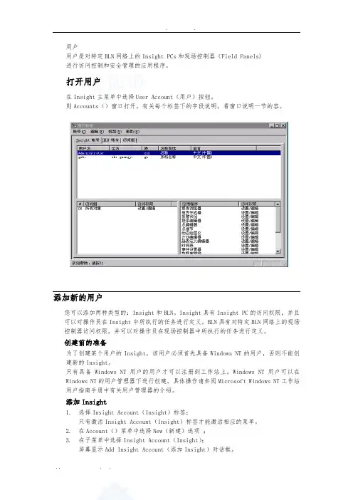
用户用户是对特定BLN网络上的Insight PCs和现场控制器(Field Panels)进行访问控制和安全管理的应用程序。
打开用户在Insight主菜单中选择User Account(用户)按钮。
则Accounts()窗口打开。
有关每个标签下的字段说明,看窗口说明一节的容。
添加新的用户您可以添加两种类型的:Insight和BLN。
Insight具有Insight PC的访问权限,并且可以对操作员在Insight中所执行的任务进行定义。
BLN具有对特定BLN网络上的现场控制器访问权限,并可以对操作员在现场控制器中所执行的任务进行定义。
创建前的准备为了创建某个用户的Insight,该用户必须首先具备Windows NT的用户,否则不能创建新的Insight。
只有具备Windows NT用户的用户才可以注册到工作站上。
Windows NT用户可以在Windows NT的用户管理器下进行创建。
具体操作请参阅Microsoft Windows NT工作站用户指南手册中有关用户管理器的介绍。
添加Insight1. 选择Insight Account(Insight)标签;只有激活Insight Account(Insight)标签才能激活相应的菜单。
2. 在Account()菜单中选择New(新建)选项;3. 在子菜单中选择Insight Account(Insight);屏幕显示Add Insight Account(添加Insight)对话框。
4. 完成Add Insight Account(添加Insight)对话框中的相应字段设置:●User Name(用户名称):Insight的用户登录名称。
可以按下拉箭头按钮,选择一个名称。
●Full Name(全名):显示用户的全名。
在您选择User Name(用户名称)的时候,该用户的全名也会同时显示了出来。
您可以接受该全名,也可以进行必要的修改。
全名主要用于日志和报告的显示。


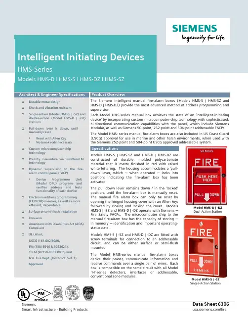
Intelligent Initiating Devices HMS-SeriesModels HMS-D I HMS-S I HMS-DZ I HMS-SZArchitect & Engineer Specifications☐Durable metal design☐Shock and vibration resistant☐Single-action (Model HMS-S | -SZ) and double-action (Model HMS-D | -DZ)stations☐Pull-down lever is down, untilmanually reset▪Reset with Allen Key▪No break rods necessary☐Custom microcomputer-chiptechnology☐Polarity insensitive via SureWireTM technology☐Dynamic supervision to the fire-alarm control panel (FACP)▪Device Programmer Unit(Model DPU) programs andverifies address and testsfunctionality of each device☐Electronic-address programming(EEPROM) is easier, as well as moreefficient, dependable☐Surface or semi-flush installation☐Two-wire☐Americans with Disabilities Act (ADA) Compliant☐UL Listed;USCG (161.002/60/0),FM (#3015946 & 3052621),CSFM (#7150-0067:0036) andNYC Fire Dept. (#202-12E, Vol. 1)Approved Product OverviewThe Siemens intelligent manual fire-alarm boxes (Models HMS-S | HMS-SZ and HMS-D | HMS-DZ) provide the most advanced method of address programming and supervision.Each Model HMS-series manual box achieves the state of an ‘intelligen t-initiating device’ by incorporating custom microcomputer-chip technology with sophisticated, bi-directional communication capabilities with the panel, which include Siemens Modular, as well as Siemens 50-point, 252-point and 504-point addressable FACPs. The Model HMS- series manual fire-alarm boxes are also included in US Coast Guard (USCG) approval for use in marine and other harsh environments, when used with the Siemens 252-point and 504-point USCG approved addressable system.SpecificationsModels HMS-S | HMS-SZ and HMS-D | HMS-DZ areconstructed of durable, molded polycarbonatematerial that is matte finished in red with raisedwhite lettering. The housing accommodates a ‘pull-down’ lever, which ─when operated ─locks intoposition; indicating the fire-alarm box has beenactivated.The pull-down lever remains down / in the ‘locked’position, until the fire-alarm box is manually reset.The manual fire alarm box can only be reset byopening the hinged housing cover with an Allen key;followed by closing and locking the cover. ModelsHMS-S | -SZ and HMS-D | -DZ operate with Siemens ─Fire Safety FACPs. The microcomputer chip to themanual fire-alarm box has the capacity of storing ─in memory ─ identification and important operating-status data.Models HMS-S | -SZ and HMS-D | -DZ are fitted withscrew terminals for connection to an addressablecircuit, and can be either surface or semi-flushmounted.The Model HMS-series manual fire-alarm boxesderive their power, communicate information andreceive commands over a single pair of wires. Eachbox is compatible on the same circuit with all Model`H’-series detectors, interfaces or addressable,conventional zone modules.Model HMS-D | -DZDual-Action StationModel HMS-S | -SZSingle-Action StationMounting DiagramDevice / Programmer Tester – Model DPUInnovative technology from Siemens ─ Fire Safety also allows all Model HMS-series intelligent manual fire-alarm boxes to be programmed via the Device Programmer / Test Unit (Model DPU). The programmer / tester is a compact, portable and menu-driven accessory that makes programming and testing of a manual fire-alarm box device faster, easier and more dependable than previous methods.Model DPU eliminates the need for mechanical-addressing mechanisms of a device because Model DPU electronically sets the address of the manual fire-alarm box into its microcomputer chip, non-volatile memory. Therefore, vibration, corrosion and other conditions -- which can compromise the functionality of mechanical-addressing mechanisms – are no longer an issue.Technical Data+ denotes (C)ountry (O)f (O)riginMODELOR TYPEPART NUMBERPRODUCTSHIPPING WEIGHTHMS-D 500-033400Addressable Manual Fire Alarm Box, Dual Action2.5 Lbs. 1.13 0z. HMS-DZ S54321-F5-A1Addressable Manual Fire Alarm Box, Dual Action[C.O.O. + – USA]HMS-S 500-033200Addressable Manual Fire Alarm Box, Single Action2.0 Lbs. 0.9 0z. HMS-SZ S54321-F6-A1Addressable Manual Fire Alarm Box, Single Action[C.O.O. + – USA] LTP 500-620490 Reset Tool Package [contains two (2) tools] 0.5 Lb. 0.23 0z. SB-5R310-019860Surface-Mounting Box 1.5 Lbs. 0.7 0z.ELECTRICALCurrent Draw (Active or Standby)0.9mAINDOOR / DRY CONDITIONSOperating Temperature Range 32° ─ 100°F (0° ─ 38°C) Operating Humidity Range 0 ─ 93%, non-condensingDetails for OrderingN OT I CE–The information contained in this data-sheet document is intended only as a summary, and is subject to change without notice.The product(s) described here has/have a specific instruction sheet(s)that cover various technical, limitation and liability information.Copies of install-type, instruction sheets – as well as the GeneralProduct Warning and Limitations document, which also containsimportant data, are provided with the product. All are availablefrom the Manufacturer.Data contained in the aforesaid type of documentation should be consultedwith a fire-safety professional before specifying or using the product.Any further questions or assistance concerningparticular problems that might arise, relative to theproper functioning of the equipment, please contact the Manufacturer.Siemens Industry, Inc.Smart Infrastructure - Building Products 8 Fernwood Road • Florham Park, NJ 07932Tel: (973) 593-2600July - 2019(Rev. 10 )。
大厦楼宇自控系统方案一、概述大厦位于。
该大厦是集酒店、商场与写字楼于一体的多功能综合性大厦,大厦建成后将具有一流的建筑结构和布局、完善的服务设施和良好便利的交通条件、先进的自动化办公设备与通信设施。
大厦设计楼高层、地下层。
建筑面积共平方米。
二、S600系统简介S600 是以集散理论为基础的成熟的楼宇自动化系统。
它具有结构灵活、适应性强、扩展方便、软件优化设备运行、操作简单等特点,很适合于改造工程需分阶段开通、设备分散、施工周期长等特点。
S600 是基于平台的系统软件包,可直接进入大厦的计算机网络集成系统,与其他进入集成系统的各子系统进行信息交换,并是集成系统中重要的环节,这也是该系统开放性的充分表现。
西门子兰吉尔是全球楼宇自动化领域著名的制造商,S600 是公认的具有号召力的产品。
可靠和实际是公司一贯的追求。
我们将秉承这一光辉的传统竭尽全力提升业主的投资。
三、系统总则1、 & 的产品是按照国际质量标准生产和制造的,选购的设备也同样是符合这一标准,完全能够满足业主的技术要求。
2、在楼宇自动化控制领域,我们有多年设计、安装、调试的丰富经验和良好信誉。
在全球各地(包括中国在内), 我们有无数的成功工程项目是我们能力的象征。
产品从大到小, 均能提供给业主最为满意的品质。
3、我们本着务实和节约的原则, 努力地提供给业主一套可行和有效经济的控制系统。
对方案中不现实的地方加以修正, 对缺漏的地方加以补充。
4、 S600 是与全球同步投放市场的最新一代楼宇自动化控制系统, 是在平台上运行的全新系统, 开放性和兼容性是这套系统开发之初的主导思想, 是适应楼宇控制市场网络化这一方向的必然产物。
能够与智能大厦的诸多系统进行通讯或参与整个大厦的管理。
5、楼宇自动化系统能够自动控制建筑物内的机电设备。
通过软件, 系统地管理相互关联的设备, 发挥设备整体的优势和潜力, 提高利用率, 优化设备的运行状态和时机(但并不影响设备的工效), 从而延长设备的服役寿命, 做到降低能源消耗, 减低维护人员的劳动强度和工时。
楼宇自动控制系统组成楼宇自动控制系统是一种利用现代科技手段对楼宇进行智能化管理和控制的系统。
它通过集成多种设备和技术,实现对楼宇内部各个系统的自动化控制,提高了楼宇的安全性、舒适性和能源利用效率,为人们的生活和工作带来了诸多便利。
一、楼宇自动控制系统的组成楼宇自动控制系统主要包括以下几个方面的组成部分:1. 入口控制系统:通过门禁、刷卡等手段实现对楼宇入口的自动化管理,确保只有授权人员可以进入。
2. 电梯控制系统:通过电梯智能化控制,实现楼宇内电梯的高效运行和安全管理。
3. 空调系统:通过温度、湿度等传感器的监测和控制,实现楼宇内空调系统的智能化调节,提供舒适的室内环境。
4. 照明系统:通过光敏传感器、定时器等设备,实现楼宇内照明系统的自动化控制,提高能源利用效率。
5. 火灾报警系统:通过烟雾、温度传感器等设备,实现楼宇内火灾的及时报警和自动灭火。
6. 安防系统:包括监控摄像头、报警器等设备,通过视频监控和报警功能,实现楼宇内安全的监控和管理。
7. 电力管理系统:通过电力监测设备和控制器,实现楼宇内电力的监测、分配和节约管理。
二、楼宇自动控制系统的优势楼宇自动控制系统的优势主要体现在以下几个方面:1. 提高安全性:通过智能化的入口控制、安防系统和火灾报警系统,保障楼宇内人员和财产的安全。
2. 提高舒适性:通过空调系统、照明系统等设备的智能化控制,提供舒适的室内环境,提高人们的生活和工作舒适度。
3. 提高能源利用效率:通过电力管理系统、照明系统等设备的智能化控制,实现能源的合理利用和节约,降低能源消耗。
4. 提高管理效率:通过楼宇自动控制系统,实现对楼宇内各个系统的集中管理和控制,提高管理效率和便利性。
5. 降低运营成本:通过楼宇自动控制系统的智能化管理和控制,减少人工管理和能源消耗,降低楼宇的运营成本。
三、楼宇自动控制系统的应用领域楼宇自动控制系统广泛应用于各种建筑物,包括商业办公楼、住宅小区、酒店、医院、学校等。
调试、验收与维护系统调试在系统及设备安装完毕后,我方向业主提交一份详细的调试程序及各控制设定点,得到业主的同意后,进行系统调试。
校线对所有接线进行严格校正,检查无误后进行下一步工作。
硬件调试对各种传感器用几种不同方法校验;对各种驱动器用手动,电动模拟工作校验;对各种DDC进行通电测试;对中央管理站设备通电测试。
现场调试对各DDC子站进行现场调试;电源工作正常;接收各种传感器信号正常;命令各种驱动器动作正常;软件工作正常,包括编程、历史报告、趋势报警、实时监测报警等;保证独立工作正常,写出明确报告,无误后进行下一步。
系统联调:整个系统通电调试,全部通讯无误;所有动态图形,动态参数监测无误;所有遥测、遥控功能正常;Insight软件各项软件工作正常;各种需后期编制的图形,程序编制完成调试成功;预设空调系统冬、夏、过渡季节工况参数,并在相应工况下进行实时跟踪调整,保证使系统达到最佳运行状态。
完工验收我方将于工程完成前半个月内,提交测试表格和试运行记录表格给业主审批。
工程完工后,立即安排业主及业主指定的有关单位对工程进行验收工作。
验收工作严格按合同中规定的技术性能指标进行,验收合格后双方签署验收合格证明。
资料提交在签约后即呈交主要产品样本给业主;呈交主要设备说明书和详尽技术资料、图样,特性曲线等给业主;呈交详尽的工程进度表给业主;工程完成后立即向业主提交操作与维修说明书;工程完成后立即向业主提交易损件及备件手册。
维护和保修系统质量保修期为:设备交货后18个月或系统调试验收后12个月,以先到者为准。
在质量保修期内向业主免费提供对设备正常运行的所有服务,必要的材料和设备。
定期派工程师到现场进行检查,每次检查及维修后写出详细书面报告,提供给业主。
并负责更换系统正常使用情况下损坏的部件;由于在设计、制造、安装不当所造成的损失,由我公司负责保修。
任何时候,接到业主通知8小时内派遣有丰富经验的工程师到现场进行维修。
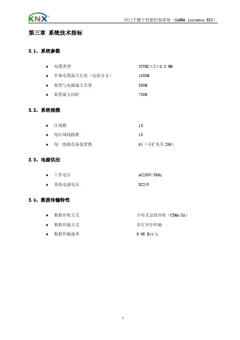
第三章 系统技术指标3.1、系统参数♦电缆类型 YCYM2×2×0.8 MM♦单条电缆最大长度(包括分支) 1000M♦装置与电源最大长度 350M♦装置最大间距 700M3.2、系统规模♦区域数 15♦每区域线路数 15♦每一线路设备装置数 64(可扩充至256)3.3、电源供应♦工作电压 AC230V/50Hz♦系统电源电压 DC24V3.4、数据传输特性♦数据存取方式 分布式总线存取(CSMA/CA)♦数据传输方式 串行异步传输♦数据传输速率 9.6K Bit/s第四章 系统详细配置4.1、系统架构照明监控管理系统主要包括照明监控工作站、网络连接控制器、单元控制继电器(控制器)、就地开关、各类传感器等。
单元控制器采用KNX/EIB现场总线连接,控制面板及各类传感器通过可编址控制EIB总线接入单元控制器或直接就近接入单元控制器,控制面板与建筑装修相协调。
系统架构拓扑示意图4.2、系统网络采用完全分布式集散控制系统(KNX/EIB),集中监控,分区控制,管理分级,通过网络系统将分布在各现场的控制器联接起来,软件与硬件分散配置。
中央停止工作不影响各分区功能和设备运行,网络通信控制也不应因此而中断。
系统分区控制完全独立,互不干扰,一个分区停止工作不影响其他分区和设备的正常运行;任意分区中任意器件损坏也不影响本区内其他器件正常工作;分区通信线路的中断不影响分区的正常运行。
分区模块化结构,支路控制,控制和调节功能由就地控制面板完成。
4.3、系统配置及技术参数参见附件《设备技术参数表》第五章 施工工艺描述5.1、KNX/EIB布线要求5.1.1.EIB线为24v低压信号线,需要单独配管,且与强电管之间的间距应大于、等于50mm,可与强电管平行铺设。
5.1.2.各个EIB开关、执行器元件都需使用标准EIB线缆连接,EIB线缆由厂商统一供应。
5.1.3.EIB线的连接结构形式多种多样,可选用星型、环型、总线型、网络型等多种连接形式,也可以互相混合使用,只需将EIB线连接到每个开关、感应器元件即可。
西门子PLC在楼控系统中的应用【摘要】介绍通过siemens的s7-200/300/400系列plc的合理配置、使用,实现s7-200/300/400系列plc在楼控系统中的应用。
【关键词】s7-200/300/400系列plc;profibus-dp;wincc;楼控;ba进入21世纪,信息技术与建筑技术的结合日趋紧密,建筑智能化系统越来越接近和丰富着人们的日常生活。
智能建筑运用先进的计算机技术、控制技术、通讯技术,为使用者与管理者提供了控制功能完善、数据处理方便、显示操作集中、运行安全可靠的建筑设备自动化系统。
通过西门子的s7-200/300/400系列plc的合理配置、使用来实现ba系统的控制,是一种有别于ddc控制系统来实现ba控制的一种全新方式。
现以某项目为例,来介绍通过西门子plc来实现楼控系统。
一、项目情况介绍大楼主楼22层,附楼4层,地下1层。
其中,主楼面积14820㎡,附楼面积15200㎡。
总监控点1551个,主要涉及大楼的空调末端、给排水、电梯、变配电、公共照明、冷热量计费、冷源(冰蓄冷)、热源(水蓄热)。
二、网络构架三、系统介绍1、各系统的监控内容(1)常规空调机组的监控内容●回风温度测量(ai)●设备故障状态监测(di)●设备运行状态监测(di)●设备手/自动状态监测(di)●过滤网阻塞报警信号(di)●设备启停控制(do)●根据回风温度传感器反馈信号来调节空调水管两通调节阀开度,使实际温度趋向设定温度(ao)(2)新风机组的监控内容●送风温度测量(ai)●设备故障状态监测(di)●设备运行状态监测(di)●设备手/自动状态监测(di))●设备启停控制(do)●监测过滤网两侧压差,根据设定值产生阻塞报警信号(di)●根据回风温度传感器反馈信号来调节空调水管两通调节阀开度,使实际温度趋向设定温度(ao)(3)给排水监控内容●水泵过载继电器状态监测,产生故障报警信号(di)●水泵运行状态监测(di)●水泵启停控制(do)●水泵手/自动状态(di)●水池高低水位信号监测(di)●水池超高超低水位报警(di)(4)变配电系统监测内容●监测变压器内部温度,异常时报警(di)●监测高压开关状态及故障状态,异常时报警(di)●监测高压电流、电压、有功功率、频率等参数(ai)●监测低压开关状态及故障状态,异常时报警(di)●监测低压电流、电压、有功功率、频率等参数(ai)(5)电梯系统监测内容●检测电梯的运行状态(di);●电梯运行时间并打印;(6)空调计费系统监测内容●回路的供水温度(ai)●回路的回水温度(ai)●回路的管路实际流量(ai)(7)照明系统监测内容●回路开关状态监测(di)●回路手/自动状态监测(di)●回路开关控制(do)(8)冷热源系统监测内容a、冷却水系统:●冷却水泵、冷却塔等设备的启停●冷却水泵、冷却塔等设备的运行、故障状态●冷却水的回水温度(ai)b、冷冻水系统●冷冻水泵等设备的启停(do)●冷冻水泵等设备的运行、故障状态(di)●冷冻水泵的频率(ao)●压差旁通阀(ao)●冷冻水的供水温度(ai)●冷冻水的回水温度(ai)●供回水压差(ai)●冷冻水供水流量(ai)c、乙二醇系统●双工况制冷主机、乙二醇泵等设备的启停(do)●双工况制冷主机制冰制冷切换(do)●双工况制冷主机、乙二醇泵等设备的运行、故障状态(di)●乙二醇泵的频率(ao)●回路调节阀(ao)●板换乙二醇侧进水温度(ai)●板换乙二醇侧出水温度(ai)●蓄冰槽进水温度(ai)●蓄冰槽出水温度(ai)d、蓄热系统●电锅炉、蓄热水泵、供热水泵启停(do)●电锅炉蓄热供热工况切换(do)●蓄热水泵、供热水泵的频率(ao)●回路调节阀(ao)●板换高温侧进水温度(ai)●板换高温侧出水温度(ai)●蓄热槽进水温度(ai)●蓄热槽出水温度(ai)2、现场的控制器配置空调末端、给排水、电梯、变配电、公共照明、冷热量计费等系统的控制点分布分散,根据各楼层设备的分布及设备控制点的数量来配置现场控制器,现场控制选用西门子s7-200系列plc。
BMS系统方案南马路五金城的BMS系统中,主要是对建筑物内各相应房间空调系统、制冷系统、制热系统、控制和集中监控管理。
我司将采用SIEMENS公司APOGEE系统。
系统是通过中央计算机系统的网络将分布在各监控现场的区域智能分站连接起来,它是基于现代控制论中分布式控制理论而设计的集散型系统。
以计算机工作站为中心,由符合RS485工业标准的网络,对合理分布于各监控现场的区域智能分站进行连接,通过特定的末端设备,实现对建筑物内空调设备采用现代计算机技术进行全面有效的监控和管理,确保所有设备处于高效,节能、合理的运行状态系统构成系统以微型计算机(中央管理工作站)为核心,采用集散式控制结构,包括以下几部分:√中央管理工作站√网络总线√现场控制机√传感器、变送器及电动执行机构等上述设备与被控对象及相应监控软件组成一套完整的控制系统。
系统网络结构BMS系统由中央站(PC)和分站及现场DDC控制器,包括子系统的区域管理器组成,根据南马路五金城的监控设备的分布情况,分站直接以以485总线连接方式与中央站连接在一起,本系统的中央站和分站之间没有主控制器和网络控制器之类的设备,保证现场控制器的独立工作能力和数据结构以及通讯速度无任何改变,保持在不同应用中数据的一致性和控制的实时性。
本系统具有同层资源共享功能,在系统主发生故障时,全部同层现场控制器之间仍能保持通讯畅通。
系统的网络能提供警报系统的高速数据传输率,分时多任务控制器的快速数据产生以及网络设备之间的上加下减的能力。
系统设计保证在一个现场控制器上产生的报警信号将会在3秒钟内出现在工作站的显示器和报警打印机上。
网络不会因某台DDC控制器离线、拆除、失电和损坏而终断。
网络设备具有信息和报警缓冲寄存器,可防止信息丢失。
网络能对错误进行自动校验、改正、以保证传输数据的可靠性。
系统具有实时时钟同步功能,能对所有的中央控制工作站、DDC控制器的实时时钟进行时间自动校正。
系统的特点√友好的图形人机交互界面√支持本地及远程的多个高性能工作站√对各类机电设备提供实时监控√功能完备的报警管理√提供大量的历史数据和趋势图√内置多种标准格式报表,并且提供用户自定义报表格式的功能√强大的应用开发工具√支持基于工业标准网络的本地及远端多客户机/服务器体系√安保数据与人力资源软件的无缝集成√针对大型用户的多客户机/服务器DSA结构√针以关键任务的热冗余功能√ActiveX技术操作界面专业的图形操作界面。