DN Product description
- 格式:doc
- 大小:59.50 KB
- 文档页数:2

Table 3: FBGA 84-Ball – x16 and 60-Ball – x4, x8 Descriptions (Continued)2Gb: x4, x8, x16 DDR2 SDRAM Ball Assignments and DescriptionsFigure 55: x4, x8 Data Output Timing – t DQSQ, t QH, and Data Valid WindowDQ DQ DQ DQ DQ DQ DQS#DQS 3CKCK#T1T2T3T4T2n T3n Data valid window Data valid window Data valid window Data valid windowNotes: 1.t HP is the lesser of t CL or t CH clock transitions collectively when a bank is active.2.t DQSQ is derived at each DQS clock edge, is not cumulative over time, begins with DQS transitions, and ends with the last valid transition of DQ.3.DQ transitioning after the DQS transition defines the t DQSQ window. DQS transitions at T2 and at T2n are “early DQS,” at T3 are “nominal DQS,” and at T3n are “late DQS.”4.DQ0, DQ1, DQ2, DQ3 for x4 or DQ[7:0] for x8.5.t QH is derived from t HP: t QH = t HP - t QHS.6.The data valid window is derived for each DQS transition and is defined as t QH - t DQSQ.2Gb: x4, x8, x16 DDR2 SDRAM READDDR2 SDRAMMT47H512M4 – 64 Meg x 4 x 8 banks MT47H256M8 – 32 Meg x 8 x 8 banks MT47H128M16 – 16 Meg x 16 x 8 banksFeatures•V DD = 1.8V ±0.1V, V DDQ = 1.8V ±0.1V•JEDEC-standard 1.8V I/O (SSTL_18-compatible)•Differential data strobe (DQS, DQS#) option•4n-bit prefetch architecture•Duplicate output strobe (RDQS) option for x8•DLL to align DQ and DQS transitions with CK •8 internal banks for concurrent operation •Programmable CAS latency (CL)•Posted CAS additive latency (AL)•WRITE latency = READ latency - 1 t CK •Programmable burst lengths: 4 or 8•Adjustable data-output drive strength•64ms, 8192-cycle refresh•On-die termination (ODT)•Industrial temperature (IT) option•RoHS-compliant•Supports JEDEC clock jitter specification Options1Marking •Configuration–512 Meg x 4 (64 Meg x 4 x 8 banks)512M4–256 Meg x 8 (32 Meg x 8 x 8 banks)256M8–128 Meg x 16 (16 Meg x 16 x 8 banks)128M16•FBGA package (Pb-free) – x16–84-ball FBGA (11.5mm x 14mm) Rev. A HG •FBGA package (Pb-free) – x4, x8–60-ball FBGA (11.5mm x 14mm) Rev. A HG •FBGA package (Pb-free) – x16–84-ball FBGA (9mm x 12.5mm) Rev. C RT •FBGA package (Pb-free) – x4, x8–60-ball FBGA (9mm x 11.5mm) Rev. C EB •FBGA package (Lead solder) – x16–84-ball FBGA (9mm x 12.5mm) Rev. C PK •Timing – cycle time– 1.875ns @ CL = 7 (DDR2-1066)-187E– 2.5ns @ CL = 5 (DDR2-800)-25E– 2.5ns @ CL = 6 (DDR2-800)-25– 3.0ns @ CL = 5 (DDR2-667)-3•Self refresh–Standard None •Operating temperature–Commercial (0°C ื T C ื +85°C)None–Industrial (–40°C ื T C ื +95°C;–40°C ื T A ื +85°C)IT •Revision:A/:CNote: 1.Not all options listed can be combined todefine an offered product. Use the PartCatalog Search on forproduct offerings and availability.2Gb: x4, x8, x16 DDR2 SDRAMFeatures。


Hypersep STH & SFH seriesHypersep — centrifugal water separatorBrief descriptionHypersep separators are very compact and easy to install and is offered with a full range of threaded and flanged air connections. It needs no external power source, and it works automaticallywithout any maintenance requirements. Hypersep separators even remove rust, oil and other impurities, significantly improving the performance of filters and other downstream equipments.All threaded models in aluminium feature unique Hiroshield surface protection treatment, applied both inside and out-side. Hiroshield ensures that Hypersep can withstand even the toughest indus-trial conditions. The result is reduced maintenance and downtime.Hypersep’s low pressure drops configu-ration keeps system energy costs at a minimum. High pressure separtators formax. operating pressure 40 bar(g).Performance overview:Air Flow m 3/h Port Size 543/8"1261/2"1803/4"3301"5401¼"7501½"1.2602"24002½"2.7603"STH STH001A STH003A STH013A STH001P STH003P STH013P STH019PVersions• Horizontal or vertical configuration • in stainless steel• for high or low air flowPED approval is offered as standard for all models. Other International pressure vessel approvals available on request.Air Flow m 3/h Port Size in out 1764DN80DN801800DN100DN802196DN100DN10022280DN125DN1253936DN150DN1254020DN150DN150SFH088SFH089SFH097SFH142SFH180SFH209SFHBULSTHSFH-00-ENProduct-Specifi cationSTH & SFH HypersepYour local authorized Parker distributor© 2014 Parker Hannifi n Corporation. All rights reserved.EMEA Product Information CentreFree phone: 00 800 27 27 5374(from AT , BE, CH, CZ, DE, DK, EE, ES, FI, FR, IE, IL, IS, IT , LU, MT , NL, NO, PL, PT , RU, SE, SK, UK, ZA)US Product Information Centre Toll-free number: 1-800-27 27 537/hzdPerformances refer to air at FAD 20 ˚C/1 bar a , and at the following working conditions: air suction 25 ˚C / 60%RH, 7 bar(g) working pressure, 35 ˚C compressed air inlet temperature, 7kPa pressure drop. Separators supplied without condensatedrain (see condensate drain models for matching drain).STH 040-046。


ALWAYS REFER TO ANY NOTIFICATIONS AT THE END OF THIS DOCUMENT REGARDING PRODUCT INSTALLATION, MAINTENANCE OR SUPPORT.(By Others)Series 78USeries 786Series 78TSUPPLY1.0 PRODUCT DESCRIPTIONAvailable Sizes• ½ – 2”/DN15 – DN50Maximum Working Pressure • 400 psi/2758 kPa/27.6 bar Operating Temperature Range• –4°F to +230°F/–20°C to +110°CFunction• Provides simplified coil circuit installation that meets optimal hydronic system design requirements Application• Hot and cold water, including treated and untreated water systems • This KOIL-KIT ™ Coil Pack includes:• (1) Series 78T Ball Valve Union Combination – Sweat x Sweat • (1) Series 78U Union Port Fitting – Sweat x Male Union • (1) TA Series 786H Balancing Valve – Sweat x SweatNOTE• The Series 78T includes a PT port and a blow-down valve. The Series 78U includes a PT port and a manual air vent.2.0 CERTIFICATI N/LISTINGSProduct designed and manufactured under the Victaulic Quality Management System, as certified by LPCB in accordance with ISO-9001:2008.Series 78T/78U Manual Koil-Kit ™ Coil Pack with TA Series 786H Sweat Globe Style Valve08.63System No.Location Submitted ByDateSpec Section Paragraph ApprovedDateSeries 78T Ball Valve Union Combination Body: Dezincification resistant (DZR) brass alloy Union: DZR brass with EPDM O-ring Tailpiece: DZR brassStem: BrassStem O-Ring Seals: EPDMHandle: Steel with vinyl gripSeries 78U Union Port FittingBody: DZR brass alloyUnion: DZR brass with EPDM O-ringSeals: EPDM O-ringTailpiece: DZR brass alloyTA Series 786H Balancing ValveValve Body and Bonnet: AMETAL® DZR brass alloy Sealing (Body/Bonnet): EPDM O-ringValve Plug: AMETAL®Seat Seal: EPDM O-ringSpindle: AMETAL®Slip Washer: Polytetrafluoroethylene (PTFE) Spindle Seal: EPDM O-ringSpring: Stainless steelHand Wheel: Polyamide and TPEMeasuring Points: AMETAL®Measuring Point Seals: EPDMMeasuring Point Caps: Polyamide and TPENOTE• AMETAL® is the dezincification-resistant brass alloy of IMI TA.Series 78T Ball Valve Union CombinationNOTE• Optional tailpieces may be ordered for reductions and for changing end configurations from sweat to threaded or threaded to sweat. If needed, specify optional tailpiece when ordering.Series 78U Union Port FittingNOTE• Optional tailpieces may be ordered for reductions and for changing end configurations from sweat to threaded or threaded to sweat. If needed, specify optional tailpiece when ordering.4.3 OPTIONAL PARTSSeries 78T/78U Union Tailpieces (Optional)Female Tailpiece Sweat Tailpiece Male TailpieceHose End Drain Valve (Optional)A hose end drain valve is factory-installed on the Series 78T.4.5 OPTIONAL PARTSProbe Port (Optional)For Series 78T and Series 78UHandle Extension (Optional)For Series 78T4.7 OPTIONAL PARTSAir VentA manual air vent is factory-installed on the Series 78U. This product can also be mounted on the Series 78T or provided loose for other piping needs.C V /K V values for flow of water at +60°F/+16°C are shown in the table.Formulas for C V and K V valuesΔP = Q 2/C V 2 ΔP = Q 2/K V 2Q = C V × √ΔPQ = K V × √ΔPSeries 78T Ball Valve Union CombinationSeries 78U Union Port FittingFlow CoefficientC v K v Q (Flow)GPM m3/hr ΔP (Pressure Drop)psibarWhere:TA Series 786H Balancing Valve Valve Selection GuideNOTES• Balancing valves should be sized in accordance with the GPM/LPM flows (and not in relation to pipeline size). Sizing balancing valves based on the minimumor maximum flow rates is not recommended. Valves should be sized using the nominal flow rate only. The Minimum Flow is calculated from the minimum open setting of the valve and a minimum pressure drop 1 Ft. WG (= 3 kPa). The Nominal Flow is calculated from the maximum open setting of the valve and the minimum recommended pressure drop, 2 Ft. WG (= 6 kPa). The Maximum Flow is calculated from the maximum open setting of the valve and the maximum pressure drop, 20 Ft. WG (= 60 kPa). A computer program, TA-Select, is available for calculation of valve handwheel pre-set position and other applications.• For information regarding Allen Wrench sizes see the Material Specifications section on page 3.• Measuring Accuracy: The hand wheel zero position is calibrated and must not be changed. Valves have an accuracy of flow measurement of 2% to 3% whenused within their recommended flow range and installed in accordance with the figure below.• For the most accurate results, a Series 734 TA SCOPE or Series 73M CMI should be used. However, any differential pressure meter may be used.The illustration relates to the accuracy of differential pressure measurement and is not an installation requirement.2 D 10 D2 D 5 D 5.2 PERF RMANCETA Series 786H Balancing Valve Cv Values for Various Handle SettingsThe values below may be used when calculating and sizing a piping system.1C V = GPM at a ΔP of 1 psi/7 kPa) through the valve at any given setting.1 psi = 2.31 ft. of H 2O 2Full open valve.For liquids other than water, the flow values from the balancing wheel can be adjusted as follows:Divide the flow rate by the square root of the specific gravity.This applies to liquids having, on the whole, the same viscosity as water, i.e. most water/glycol mixtures and water/brine solutions at room temperature. At low temperatures, the viscosity increases and laminar flow may occur in certain valves. The risk increases with small valves, low settings and low differential pressures.A computer program (Hy-Select) is available for calculation of pre-setting values and other applications. When the flow setting is verified or changed to the final setting, the memory stop should be set. Contact Victaulic for further information. When Δp and the design flow rate are known, use the formula shown to calculate the C V value.A computer program, Hy-Select, is available from Victaulic for calculation of pre-setting values and other applications.5.4 PART CODES08.63 11841 Rev B Updated 04/2020 © 2020 Victaulic Company. All rights reserved.User Responsibility for Product Selection and SuitabilityEach user bears final responsibility for making a determination as to the suitability of Victaulic products for a particular end-use application, in accordance with industry standards and project specifications, and the applicable building codes and related regulations as well as Victaulic performance, maintenance, safety, and warninginstructions. Nothing in this or any other document, nor any verbal recommendation,advice, or opinion from any Victaulic employee, shall be deemed to alter, vary, supersede, or waive any provision of Victaulic Company's standard conditions of sale, installation guide, or this disclaimer.Intellectual Property RightsNo statement contained herein concerning a possible or suggested use of any material, product, service, or design is intended, or should be constructed, to grant any license under any patent or other intellectual property right of Victaulic or any of its subsidiaries or affiliates covering such use or design, or as a recommendation for the use of suchmaterial, product, service, or design in the infringement of any patent or other intellectual property right. The terms “Patented” or “Patent Pending” refer to design or utility patents or patent applications for articles and/or methods of use in the United States and/or other countries.NoteThis product shall be manufactured by Victaulic or to Victaulic specifications. Victaulic recommends all products to be installed in accordance with current IMI TA installation/assembly instructions. Victaulic and IMI TA reserve the right to change productspecifications, designs and standard equipment without notice and without incurring obligations.InstallationReference should always be made to the current IMI TA installation/assembly instructions for the product you are installing. For coupling and strainer installation, reference should always be made to the I-100 Victaulic Field Installation Handbook for the product you are installing. Handbooks are included with each shipment of Victaulic products for complete installation and assembly data, and are available in PDF format on our website at WarrantyRefer to the Warranty section of the current Price List or contact Victaulic for details.TrademarksVictaulic and all other Victaulic marks are the trademarks or registered trademarks of Victaulic Company, and/or its affiliated entities, in the U.S. and/or other countries.7.0 REFERENCE MATERIALS08.16: Victaulic Balancing Valves - TA Series 786H/787H/788/789 and Series 78KH I-KOIL-KIT: Victaulic KOIL-KIT™ Coil Pack Installation and Maintenance Instructions11。


DataOrdering data Product type description BS655-Z22-DN Article number (order number)153031627EAN (European Article Number)4030661533087Approval - StandardsCertificatesTÜVcULus CCC CNCAGeneral dataStandardsIEC 60947-5-1 EN 620Enclosure materialGrey cast iron, painted Material of the contacts, electrical SilverMaterial of the cover Grey cast iron, painted Gross weight6,075 g General data - Features Number of auxiliary contacts 2Number of safety contacts2BS655-Z22-DNMetal enclosureSwitching point settingProtection class IP66, IP67Central connection terminalWide range of alternative actuators Platform concept with different function unitsSymmetry thanks to toothed, centrally located shaftSafety appraisalStandards ISO 13849-1Mission Time20 Year(s)Safety appraisal - Safety outputsB10d Normally-closed contact (NC)2,000,000 OperationsMechanical dataMechanical life, minimum1,000,000 Operations Positionierschritte für den Betätiger10 °Mechanical data - Connection techniqueCable entry 2 x M25 x 1.5Cable section, minimum0.5 mm², flexible Cable section, maximum 2.5 mm², flexibleAmbient conditionsDegree of protection IP66 to IEC 60529 IP67 to IEC 60529Ambient temperature, minimum-40 °C Ambient temperature, maximum+70 °C Protection rating IAmbient conditions - Insulation valueRated impulse withstand voltage U imp 4 kV Degree of pollution to IEC/EN 60947-13Electrical dataThermal test current 6 A Utilisation category AC-15230 VAC Utilisation category AC-15 3 A Utilisation category DC-1324 VDC Utilisation category DC-13 3 AElectrical data - Communication protocolsField bus DuplineElectrical data - DuplineOperating voltage8.2 VDC Operating current0.1 mARated impulse withstand voltage U imp0.8 kVCable section, minimum 0.2 mm², rigid0.25 mm², flexibleCable section, maximum 2.5 mm², flexible 4 mm², rigidOrdering codeProduct type description:BS65(1)(2)(3)(4)(1)5Grey cast iron, painted6thermosetting resin(2)Z22Snap action 2 NO contact / 2 NC contactT22Slow action, 2 NO contacts / 2 NC contactsZ33Snap action, 3 NO contacts / 3 NC contactsT33Slow action, 3 NO contacts / 3 NC contacts(3)without without indicator lampG024Indicator lamp (only for Z/T22), red (24 VDC)G115Indicator lamp (only for Z/T22), red (115 VAC)G230Indicator lamp (only for Z/T22), red (230 VAC)(4)without Standard version (without Dupline® input module)DN With integrated Dupline® input modulePicturesProduct picture (catalogue individual photo)ID: khds-f22| 15,4 kB | .png | 74.083 x 49.389 mm - 210 x 140Pixel - 72 dpi| 157,5 kB | .jpg | 352.778 x 235.303 mm - 1000 x 667Pixel - 72 dpiDimensional drawing basic componentID: kbs65g01| 98,3 kB | .jpg | 352.778 x 209.55 mm - 1000 x 594Pixel - 72 dpi| 3,5 kB | .png | 74.083 x 44.097 mm - 210 x 125 Pixel- 72 dpiDimensional drawing basic componentID: kbs65g02| 71,6 kB | .jpg | 352.778 x 167.922 mm - 1000 x 476Pixel - 72 dpi| 5,5 kB | .jpg | 89.253 x 42.686 mm - 253 x 121 Pixel -72 dpi| 2,9 kB | .png | 74.083 x 35.278 mm - 210 x 100 Pixel- 72 dpiDimensional drawing basic componentID: kbs65g03| 11,9 kB | .jpg | 115.711 x 63.853 mm - 328 x 181Pixel - 72 dpi| 4,7 kB | .png | 74.083 x 40.922 mm - 210 x 116 Pixel- 72 dpi| 127,4 kB | .jpg | 352.778 x 195.439 mm - 1000 x 554Pixel - 72 dpiK.A. Schmersal GmbH & Co. KG, Möddinghofe 30, D-42279 WuppertalThe details and data referred to have been carefully checked. Images may diverge from original. Further technical data can be found in the manual. Technical amendments and errors possible.Generated on 03/05/2021 03:56:39。

B252•ApplicationStainless Steel Ball and StemType overviewType DN B25250Technical dataFunctional dataValve size [mm]2" [50]Fluidchilled or hot water, up to 60% glycol Fluid Temp Range (water)0...250°F [-18...120°C]Body Pressure Rating 400 psi Close-off pressure ∆ps 200 psiFlow characteristic equal percentage Servicing maintenance-free Flow Pattern 2-way Leakage rate0% for A – AB Controllable flow range 75°Cv85Cv Flow RatingA-port: as stated in chart B-port: 70% of A – AB CvMaterials Valve body Nickel-plated brass body Spindle stainless steel Spindle seal EPDM (lubricated)SeatPTFE Characterized disc stainless steel Pipe connection NPT female ends O-ring EPDM (lubricated)Ballstainless steel Suitable actuators Non-Spring ARB(X)SpringAFRB(X)Safety notesWARNING: This product can expose you to lead which is known to the State of California to cause cancer and reproductive harm. For more information go to Product featuresThis valve is typically used in air handling units on heating or cooling coils, and fan coil unit heating or cooling coils. Some other common applications include Unit Ventilators, VAV box re-heat coils and bypass loops. This valve is suitable for use in a hydronic system with variable flow.B252 Flow/Mounting detailsTwo-way valves should be installed with thedisc upstream.DimensionsType DNB25250ARB, ARXA B C D E F H110.2" [260] 4.9" [125]7.7" [196] 6.0" [152] 1.7" [44] 1.7" [44] 1.2" [30]ARB N4, ARX N4, NRB N4, NRX N4A B C D E F11.4" [289] 4.9" [125]9.8" [249]7.6" [194] 3.1" [80] 3.1" [80]ARQB, ARQXA B C D E F H1H29.9" [251] 4.9" [125]7.5" [191] 6.1" [155] 2.3" [58] 2.3" [58]0.8" [20]0.6" [15]B252AFRB, AFRXA B C D E F11.3" [286] 4.9" [125]10.6" [268]8.9" [225] 2.0" [51] 2.0" [51]AFRB N4, AFRX N4A B C D E F13.0" [330] 4.9" [125]10.3" [262]9.3" [235] 3.4" [86] 3.4" [86]AFRX24-MFTModulating, Spring Return, 24 V, Multi-Function Technology®Technical dataElectrical dataNominal voltageAC/DC 24 V Nominal voltage frequency 50/60 Hz Power consumption in operation 7.5 W Power consumption in rest position 3 WTransformer sizing 10 VA (class 2 power source)Electrical Connection18 GA appliance or plenum cables, 3 ft [1 m], 10 ft [3 m] or 16ft [5 m], with or without 1/2" conduit connectorOverload Protectionelectronic throughout 0...95° rotation Functional dataOperating range Y 2...10 VOperating range Y note 4...20 mA w/ ZG-R01 (500 Ω, 1/4 W resistor)Input Impedance100 kΩ for 2...10 V (0.1 mA), 500 Ω for 4...20 mA, 1500 Ω for PWM, On/Off and Floating point Operating range Y variable Start point 0.5...30 V End point 2.5...32 VOptions positioning signal variable (VDC, PWM, on/off, floating point)Position feedback U 2...10 V Position feedback U note Max. 0.5 mA Position feedback U variable VDC variable Direction of motion motor selectable with switchDirection of motion fail-safe reversible with cw/ccw mounting Manual override 5 mm hex crank (3/16" Allen), supplied Angle of rotation 90°Running Time (Motor)150 s / 90°Running time motor variable 70...220 s Running time fail-safe <20 s @ 20°C Angle of rotation adaptation off (default)Noise level, motor 45 dB(A)Noise level, fail-safe 62 dB(A)Position indicationMechanical Safety dataDegree of protection IEC/EN IP54Degree of protection NEMA/UL NEMA 2Enclosure UL Enclosure Type 2Agency ListingcULus acc. to UL60730-1A/-2-14, CAN/CSA E60730-1:02, CE acc. to 2014/30/EU and2014/35/EU; Listed to UL 2043 - suitable for use in air plenums per Section 300.22(c) of the NEC and Section 602.2 of the IMC Quality Standard ISO 9001Ambient temperature-22...122°F [-30...50°C]AFRX24-MFTFootnotesSafety dataStorage temperature -40...176°F [-40...80°C]Ambient humidity Max. 95% RH, non-condensing Servicingmaintenance-freeMaterialsHousing material Galvanized steel and plastic housing†Rated Impulse Voltage 800V, Type of action 1.AA, Control Pollution Degree 3AccessoriesGatewaysDescriptionType Gateway MP to BACnet MS/TP UK24BAC Gateway MP to Modbus RTU UK24MOD Gateway MP to LonWorksUK24LON Electrical accessoriesDescriptionType Service Tool, with ZIP-USB function, for programmable andcommunicative Belimo actuators, VAV controller and HVAC performance devicesZTH USService toolsDescriptionTypeConnection cable 10 ft [3 m], A: RJ11 6/4 ZTH EU, B: 3-pin Weidmüller and supply connectionZK4-GEN Service Tool, with ZIP-USB function, for programmable and communicative Belimo actuators, VAV controller and HVAC performance devicesZTH USElectrical installationINSTALLATION NOTESActuators with appliance cables are numbered.Provide overload protection and disconnect as required.Actuators may also be powered by DC 24 V.Only connect common to negative (-) leg of control circuits.A 500 Ω resistor (ZG-R01) converts the 4...20 mA control signal to 2...10 V.Control signal may be pulsed from either the Hot (Source) or Common (Sink) 24 V line.For triac sink the Common connection from the actuator must be connected to the Hotconnection of the controller. Position feedback cannot be used with a triac sink controller; theactuator internal common reference is not compatible.IN4004 or IN4007 diode. (IN4007 supplied, Belimo part number 40155).Actuators may be controlled in parallel. Current draw and input impedance must be observed.Master-Slave wiring required for piggy-back applications. Feedback from Master to controlinput(s) of Slave(s).Meets cULus requirements without the need of an electrical ground connection.Warning! Live electrical components!During installation, testing, servicing and troubleshooting of this product, it may be necessary to work with live electrical components. Have a qualified licensed electrician or other individual who has been properly trained in handling live electrical components perform these tasks. Failure to follow all electrical safety precautions when exposed to live electrical components could result in death or serious injury.AFRX24-MFT Wiring diagramsOn/Off Floating PointVDC/mA Control PWM ControlOverride Control Master - Slave。

产品介绍Productdescription使⽤清洁燃⽓的低温燃烧器Low temperature burner for use with clean fuel gases 在30%的过剩空⽓下,氮氧化物排放只有个位数Single digit NOx emissions at 30% excess air 低过剩空⽓要求下,⾼效率High efficiency with low excess air requirements 麦克森XPO?低温燃烧器,适⽤于间接液体加热应⽤,包含:MAXON XPO? burners are low temperature burners for use in liquid backed applications, including:XPO?燃烧器要求很低的过剩空⽓,所以运⾏效率⾼。
其设计旨在更⽅便地对现有的液体加热应⽤进⾏改造。
XPO? burners provide high efficiency operation with low excess air requirements. They are designed for ease of retrofitting into existing liquid backed applications.XPO?燃烧器有两种基础版本可供选择:XPO? burners are available in two basic versions: 配备整体风机的⼀体式燃烧器(PB )版本Packaged (PB) with integral combustion air blower为扩⼤燃烧能⼒,使⽤外部⽓源的外部风机(EB )版本External blower (EB) for use with an externalcombustion air source for extended capacities⽆论是⼀体式版本(PB )还是外部风机版本(EB ),其风管长度均有两种不同选择:610毫⽶或1220毫⽶。
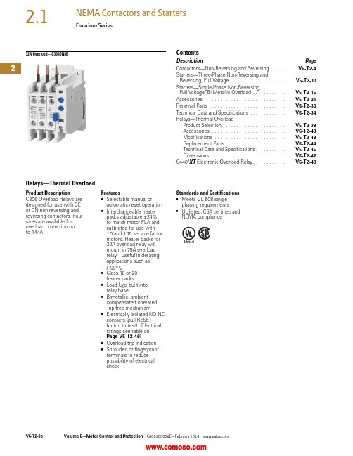
232A Overload—C306DN3BContentsDescription PageContactors—Non-Reversing and Reversing. . . . . .V5-T2-4Starters—Three-Phase Non-Reversing andReversing, Full Voltage . . . . . . . . . . . . . . . . . . . .V5-T2-10Starters—Single-Phase Non-Reversing,Full Voltage, Bi-Metallic Overload . . . . . . . . . . . .V5-T2-15Accessories . . . . . . . . . . . . . . . . . . . . . . . . . . . . . .V5-T2-21Renewal Parts . . . . . . . . . . . . . . . . . . . . . . . . . . . .V5-T2-30Technical Data and Specifications . . . . . . . . . . . . .V5-T2-34Relays—Thermal OverloadProduct Selection . . . . . . . . . . . . . . . . . . . . . . .V5-T2-39Accessories. . . . . . . . . . . . . . . . . . . . . . . . . . . .V5-T2-43Modifications . . . . . . . . . . . . . . . . . . . . . . . . . .V5-T2-43Replacement Parts . . . . . . . . . . . . . . . . . . . . . .V5-T2-44Technical Data and Specifications. . . . . . . . . . .V5-T2-45Dimensions. . . . . . . . . . . . . . . . . . . . . . . . . . . .V5-T2-47C440/XT Electronic Overload Relay. . . . . . . . . . . .V5-T2-48Relays—Thermal OverloadProduct DescriptionC306 Overload Relays aredesigned for use with CEor CN non-reversing andreversing contactors. Foursizes are available foroverload protection upto 144A.Features●Selectable manual orautomatic reset operation●Interchangeable heaterpacks adjustable ±24%to match motor FLA andcalibrated for use with1.0 and 1.15 service factormotors. Heater packs for32A overload relay willmount in 75A overloadrelay—useful in deratingapplications such asjogging●Class 10 or 20heater packs●Load lugs built intorelay base●Bimetallic, ambientcompensated operated.Trip free mechanism●Electrically isolated NO-NCcontacts (pull RESETbutton to test). (Electricalratings see table onPage V5-T2-46)●Overload trip indication●Shrouded or fingerproofterminals to reducepossibility of electricalshockStandards and Certifications●Meets UL 508 single-phasing requirements●UL listed, CSA certified andNEMA complianceV5-T2-38Volume 5—Motor Control and Protection CA08100006E—February Volume 5—Motor Control and Protection CA08100006E—February V5-T2-392Freedom SeriesProduct SelectionC306 Thermal Overload RelaysContactorsStandalone ApplicationsNotes1 NEMA Sizes 5–8 use the 32A overload in conjunction with CTs.2 Series B overload relays have load lugs built into relay base and will only accept Series B heater packs. These relays can be directly attached to contactor or they can be DIN rail or panel mounted using adapter on Page V5-T2-44.3 These relays can be panel mounted only.4 Overload relay assembled with mounting adapter for DIN rail or panel mount.5 Panel mount only.6 NEMA Sizes 5–8 use the 32A overload in conjunction with CTs.NEMA Size Maximum Ampere Rating Number of Poles Open Type NEMA 1 Enclosed Catalog Number Catalog Number 00, 032 23C306DN3B C306DG3B 1, 275 23C306GN3B C306GG3B 3105 33C306KN3—414433C306NN3—5–8 1————NEMA SizeMaximum Ampere Rating Number of Poles Open Type Catalog Number 00, 0, 1 4323C306DT3B 1 4753C306GT3B 3 51053C306KN34 51443C306NN35–8 6———C306DN3BC306GN3BC306DT3BC306GT3B2Heater Pack SelectionHeater packs H2001B toH2017B and H2101B toH2117B are to be used onlywith Series B overload relaysCatalog Numbers C306DN3B(Part No. 10-7016) andC306GN3B (Part No.10-7020). The load lugs arebuilt into the overload relaybase to allow load wiring priorto heater pack installation.The previous heater designhad integral load lugs. TheSeries B heater packs areelectrically equivalent to theprevious heater design.Heaters H2018-3 to H2024-3have not changed.Starters with Series B Overload Relays 1Standard T rip—Class 20 HeaterNotes1 The series of a starter is the last digit of the listed catalog number. Example: AN16DN0AB.2 Heater packs are shipped three to a carton. catalog numbers are for three heater packs.NEMA—AN Type IEC—AE TypeSize Series Size Series00–0C A–F C1–2B G–K B5B G–K B6C G–K B7–8B G–K BOverload Relay SizeMotor Full Load Ampere RatingCatalog Number 2Dial PositionA B CDFor Use with NEMA Sizes 00–0 Series C, NEMA Sizes 1–2 Series B; IEC Sizes A–F Series C, IEC Sizes G–K Series B32A or 75A0.2540.3060.3590.411H2001B-30.3750.4520.5300.607H2002B-30.5600.6760.7910.907H2003B-30.8140.983 1.15 1.32H2004B-31.20 1.45 1.71 1.96H2005B-31.792.16 2.53 2.90H2006B-32.15 2.603.04 3.49H2007B-33.23 3.904.565.23H2008B-34.555.506.457.40H2009B-36.758.179.5811.0H2010B-39.1410.812.414.0H2011B-314.016.919.922.8H2012B-318.722.726.730.7H2013B-323.528.533.538.5H2014B-3For Use with NEMA Size 2, IEC Sizes G–K Only, Series B75A29.034.039.144.1H2015B-339.645.551.557.4H2016B-353.960.967.974.9H2017B-3Heater PackH2001B–H2017BV5-T2-40Volume 5—Motor Control and Protection CA08100006E—February Volume 5—Motor Control and Protection CA08100006E—February V5-T2-412Freedom SeriesStandard T rip—Class 20 Heater, continuedNotes1 Heater packs are shipped three to a carton. catalog numbers are for three heater packs.2 Sizes 5–8 and IEC P–Z use the 32A overload relay with current transformers.Overload Relay SizeMotor Full Load Ampere Rating Catalog Number 1Dial PositionABCDFor Use with NEMA Sizes 3–4, IEC Sizes L–N Only—Series A 105A or 144A8.09.210.311.5H2025-311.412.814.315.7H2026-314.315.717.419.0H2027-318.020.222.324.5H2018-324.627.630.533.4H2019-333.537.541.545.6H2020-345.751.256.762.1H2021-362.269.777.184.6H2022-384.795.0105.0115.0H2023-3106.0118.0131.0144.0H2024-3For Use with Size 5 Starters—Series B and IEC P , R and S with 300/5 CT 32A 249596979H2004B-37287103118H2005B-3107130152174H2006B-3129156182209H2007B-3194234274—H2008B-3For Use with Size 6 Starters Only—Series B and IEC T–V with 600/5 CT 32A 2144174205235H2005B-3215259304348H2006B-3258312365419H2007B-3388468547627H2008B-3For Use with Size 7 Starters Only—Series B and IEC W–X with 1000/5 CT 32A 2163197230264H2004B-3240290342392H2005B-3358432506580H2006B-3430520608698H2007B-3646780912—H2008B-3For Use Size 8 Starters Only—Series B and IEC Z with 1500/5 CT 32A 2244295345396H2004B-3360435513588H2005B-3537648759870H2006B-36457809121047H2007B-396911701368—H2008B-3Heater Pack H2018–H2024V5-T2-42Volume 5—Motor Control and Protection CA08100006E—February 2Fast T rip—Class 10 HeaterNotes1 Heater packs are shipped three to a carton. catalog numbers are for three heater packs.2 Sizes 5–8 and IEC P–Z use the 32A overload relay with current transformers.Overload Relay SizeMotor Full Load Ampere Rating Catalog Number 1Dial PositionABCDFor Use with NEMA Sizes 00–0 Series C, NEMA Sizes 1–2 Series B; IEC Sizes A–F Series C, IEC Sizes G–K Series B 32A or 75A0.2600.3130.3670.420H2101B-30.3840.4640.5430.623H2102B-30.5700.6880.8060.924H2103B-30.846 1.02 1.20 1.37H2104B-31.28 1.55 1.83 2.10H2105B-31.92 2.33 2.74 3.15H2106B-32.30 2.79 3.28 3.77H2107B-33.38 4.10 4.82 5.54H2108B-34.96 6.037.098.16H2109B-37.078.5810.111.6H2110B-39.6011.212.814.4H2111B-314.417.520.723.8H2112B-318.721.825.028.1H2113B-323.527.331.034.8H2114B-3For Use with Size 2, IEC Sizes G–K Only—Series B75A28.332.637.041.3H2115B-336.642.348.153.8H2116B-353.860.867.974.9H2117B-3For Use with Size 5 Starters Only—Series B and IEC P , R and S with 300/5 CT 32A 251617282H2104B-37793110126H2105B-3115140164189H2106B-3138167197226H2107B-3203246289—H2108B-3For Use with Size 6 Starters Only—Series B and IEC T–V with 600/5 CT 32A 2154186220252H2105B-3230280329378H2106B-3276335394452H2107B-3406492578—H2108B-3For Use with Size 7 Starters Only—Series B and IEC W–X with 1000/5 CT 32A 2169204240274H2104B-3256310366420H2105B-3384466543630H2106B-3460558656754H2107B-3676820——H2108B-3For Use with Size 8 Starters Only—Series B and IEC Z with 1500/5 CT 32A 2254306360411H2104B-3384465549630H2105B-3576699822945H2106B-36908379841131H2107B-310141230——H2108B-3Heater Pack H2101B–H2117BVolume 5—Motor Control and Protection CA08100006E—February V5-T2-432Freedom SeriesAccessoriesDIN Rail and Panel Mounting Adapter These adapters are required when component overload relays are to be separately mounted. The terminal base adapter includes line terminals and connects with the overload relays on Page V5-T2-39.DIN Rail and Panel Mounting AdapterLocking Cover for Overload Relay—C306 Only Snap-on transparent or opaque plastic panel for covering access port to the overload relay trip settingdial—helps prevent accidental or unauthorized changes to trip and reset setting.Locking Cover for Overload Relay—C306 OnlyNote1This Series B adapter will accept Series A or B overload relays (C306GN3 or C306GN3B), C306TB2 can only be used with C306GN3.Description Catalog Number For 32A overload relay C306TB1For 75A overload relayC306TB2B 1C306TB1DescriptionMin. Order Qty.(Std. Pkg.)Catalog Number Clear cover, no accessibility50C320PC3Gray cover, no accessibility with auto only nib50C320PC4Gray cover, no accessibility withmanual only nib50C320PC5Gray cover with FLA dial accessibility, A, B, C, D positions and auto only nib50C320PC6Gray cover with FLA dial accessibility, A, B, C, D positions and manual only nib50C320PC7Overload Relay CoverModificationsC306 Thermal Overload Relays with Mounting AdapterConsists of a thermal overload relay mounted to a terminal base adapter—permits fast and easy installation.C306 Thermal Overload Relays with Mounting AdapterDescription Catalog Number C306DN3B + C306TB1C306DT3B C306GN3B + C306TB2BC306GT3B。

March 2009Product Family OverviewProduct DescriptionFreedom Series starters and contactors feature a compact, space-saving design, using state-of-the-art technology and the latest in high strength, impact and temperature resistant insulating materials.FeaturesFreedom NEMA■Adjustable Bimetallic AmbientCompensated Overload relays with interchangeable heater packs — available in three basic sizes,covering applications up to 900 hp — reducing the number of different contactor/overload relay combina-tions that have to be stocked. Fixed heater overloads are optional.■Electronic Solid-State Overload Relay (C396) available as a stand-alone unit and assembled with Freedom Contactor.■ A full line of snap-on accessories common to both IEC and NEMA devices — top and side mounted auxiliary contacts, solid-state and pneumatic timers, etc.■Straight-through wiring — line lugs at top, load lugs at bottom.■Horizontal or vertical mounting on upright panel for application freedom.■Screw type power terminals have captive, backed-out self-lifting pres-sure plates with ± screws — reduced wiring time.■Accessible terminals for easy wir-ing. Optional fingerproof shields available to prevent electrical shock.■Top located coil terminals conve-nient and readily accessible. 45 mm contactor magnet coils have three terminals, permitting either top or diagonal wiring — easy to replace European or U.S. style starters or contactors without changing wiring layout.■Encapsulated dual voltage/frequency magnet coils —permanently marked with voltage, frequency and part number. NEMA Sizes 00 – 0 have non-encapsulated coils as standard.■Designed to meet or exceed NEMA, UL, CSA, VDE, BS and other interna-tional standards and listings.■American engineering — built by Eaton, using the latest in statistical process control methods to produce high quality, reliable products.■Sized based on standard NEMA classifications.■Easy coil change and inspectable/replaceable contacts.■Available in Open and NEMA Type 1, 3R, 4/4X and 12 enclosures.Standards and Certifications■Standard: Designed to meet or exceed UL, NEMA, IEC, CSA, VDE and BS.■UL listed: UL File #E1491, Guide #NLDX — Open and NEMA 1, 4, 12 Enclosed■CSA Certified: CSA File #LR353, Class #321104 Open and NEMA 1 EnclosedISO 9000 CertificationWhen you turn to Eaton’s Cutler-Hammer Products, you turn to quality. The International Standards Organiza-tion (ISO) has established a series of standards acknowledged by 91 indus-trialized nations to bring harmony to the international quest for quality. The ISO certification process covers 20 quality system elements in design, production and installation that must conform to achieve registration. This commitment to quality will result in increased product reliability and total customer satisfaction.Short Circuit ProtectionFuses and Inverse-Time Circuit Breakers may be selected per Article 430, Part D of the National Electrical Code to pro-tect motor branch circuits from fault conditions. If higher ratings or settings are required to start the motor, do not exceed the maximum as listed in Exception No. 2, Article 430-52.NEMA AN16DN0AB NEMA Size 1 StarterNEMA Size 1 ContactorSeries B1 32A OverloadC396 Electronic OverloadMarch 2009Starters — 3-Phase Non-reversing and Reversing, Full VoltageContentsDescriptionPageProduct Family OverviewProduct Description. . . . . . 33-68Features . . . . . . . . . . . . . . . 33-68Standards andCertifications . . . . . . . . . . 33-68Catalog NumberSelection . . . . . . . . . . . . . 33-69Starters — 3-Phase Non-reversing and Reversing, Full Voltage, Bi-Metallic OverloadProduct Description. . . . . . 33-73Features . . . . . . . . . . . . . . . 33-73Technical Data . . . . . . . . . . 33-74Wiring Diagrams . . . . . . . . 33-74Product Selection. . . . . . . . 33-75Starters — 3-Phase Multispeed, Bi-Metallic OverloadProduct Selection. . . . . . . . 33-76Starters — Single-PhaseNon-reversing, Full Voltage, Bi-Metallic OverloadProduct Description. . . . . . 33-77Wiring Diagrams . . . . . . . . 33-77Product Selection. . . . . . . . 33-77Starters — 3-Phase Non-reversing and Reversing, Full Voltage,C386 Electronic Overload . . 33-78Technical Data . . . . . . . . . . . . . 33-79Accessories . . . . . . . . . . . . . . . 33-82Auxiliary Contacts . . . . . . . 33-86DC Magnet Coils . . . . . . . . 33-88Mounting Plates. . . . . . . . . 33-89Special Modifications . . . . . . . 33-90Renewal Parts . . . . . . . . . . . . 33-91Dimensions . . . . . . . . . . . . . . . 33-94Product DescriptionNon-reversingThree-phase, full voltage magnetic starters are most commonly used to switch AC motor loads. Starters con-sist of a magnetically actuated switch (contactor) and an overload relay assembled together.ReversingThree-phase, full voltage magnetic starters are used primarily for revers-ing of 3-phase squirrel cage motors. They consist of two contactors and a single overload relay assembledtogether. The contactors are mechani-cally and electrically interlocked to prevent line shorts and energization of both contactors simultaneously.Features■Bimetallic Ambient Compensated Overload relays — available in three basic sizes covering applications up to 900 hp — reducing number of different contactor/overload relay combinations that have to be stocked.These overload relays feature:❑Selectable Manual or Automatic Reset operation.❑Interchangeable heater packs adjustable ±24% to match motor FLA and calibrated for 1.0 and 1.15 service factors. Heater packs for smaller overload relay will mount in larger overload relay — useful in derating applications such as jogging.❑Load lugs built into relay base.❑Single-phase protection, Class 20 or Class 10 trip time.❑Overload trip indication.❑Electrically isolated NO-NC con-tacts (pull RESET button to test).■The C396 is a self-powered, robust electronic overload designed for integrate use with Freedom NEMA contactors.❑Tiered feature set to provide cov-erage specific to your application.❑Broad 5:1 FLA range for maxi-mum flexibility.❑Coverage from 0.05 – 1500 Amps to meet all your needs.■Long life twin break, silver cadmium oxide contacts — provide excellent conductivity and superior resistance to welding and arc erosion. Gener-ously sized for low resistance and cool operation.■Designed to 3,000,000 electrical operations at maximum hp ratings up through 25 hp at 600V.■Steel mounting plate standard on all open type starters.■Wired for separate or common control.Non-reversing■Holding circuit contact(s) supplied as standard:❑Sizes 00 – 3 have a NO auxiliary contact block mounted on right-hand side (on Size 00, contact occupies 4th power pole position — no increase in width).❑Sizes 4 – 5 have a NO contact block mounted on left side.❑Sizes 6 – 7 have a 2NO/2NC contact block on top left.❑Size 8 has a NO/NC contact block on top left back and a NO on top right back.Reversing■Each contactor (Size 00 – 8) supplied with one NO-NC sidemounted contact block as standard. NC contacts are wired as electrical interlocks.NEMA Size 1 — Cat. No. AN16DN0ABNEMA Size 1 — Cat. No. AN56DN0ABMarch 2009Starters — 3-Phase Non-reversing and Reversing, Full VoltageTechnical DataTable 33-96. Wire (75°C) Sizes — AWG or kcmil — NEMA Sizes 00 – 2 — Open and EnclosedᕃTwo compartment box lug.ᕄMinimum per NEC. Maximum wire size: Sizes 00 and 0 to 8 AWG and Sizes 1 – 2 to 2 AWG.Table 33-97. Wire (75°C) Sizes — AWG or kcmil — NEMA Sizes 3 – 8 — Open and EnclosedᕅMinimum per NEC. Maximum wire size: Sizes 00 and 0 to 8 AWG and Sizes 1 – 2 to 2 AWG.Wiring DiagramsFigure 33-24. Typical Wiring Diagrams — Three-Phase and Single-Phase ApplicationsNEMA SizeWire Size ᕄ Cu OnlyPower Terminals — Line0001212 – 16 AWG stranded, 12 – 14 AWG solid 8 – 16 AWG stranded, 10 – 14 AWG solid 8 – 14 AWG stranded or solid3 – 14 AWG (upper) and/or 6 – 14 AWG (lower) stranded or solid ᕃPower Terminals — Load — Cu Only (stranded or solid)00 – 01 – 214 – 6 AWG stranded or solid 14 – 2 AWG stranded or solidControl Terminals — Cu Only12 – 16 AWG stranded, 12 – 14 AWG solidNEMA SizeWire Size ᕅPower Terminals — Line and Load31/0 – 14 AWG Cu/Al4Open — 3/0 – 8 AWG Cu; Enclosed — 250 kcmil — 6 AWG Cu/Al 5678750 kcmil — 2 AWG; or (2) 250 kcmil — 3/0 AWG Cu/Al (2) 750 kcmil — 3/0 AWG Cu/Al (3) 750 kcmil — 3/0 AWG Cu/Al (4) 750 kcmil — 1/0 AWG Cu/AlControl Terminals — Cu Only12 – 16 AWG stranded, 12 – 14 AWG solidTable 33-98. Plugging and Jogging Service Horsepower Ratings ᕆᕆMaximum horsepower where operation is interrupted more than 5 times per minute, or more than 10 times in a 10 minute period. NEMA Standard ICS2-1993 table 2-4-3.Kits and Accessories■Auxiliary Contacts, contactor mounted — Pages 33-86 – 33-87. ■Transient Suppressor, for magnet coil — Pages 33-84.■Timers — Solid-State andPneumatic, mount on contactor — Page 33-83.Renewal Parts Publication Numbers■See Page 33-91.NEMA Size 200V 230V 460V 575V 000123—1-1/237-1/2151/21-1/2310201/22515301/2251530456256012530751506015030060150300March 2009Starters — 3-Phase Non-reversing and Reversing, Full Voltage, Bi-Metallic OverloadProduct SelectionWhen Ordering Supply■Catalog Number■Heater pack number (see selectiontable, Pages 33-107 – 33-108) or full load current.Table 33-99. Type AN16/AN56 NEMA — Manual or Automatic Reset Overload Relay — Non-reversing and ReversingNote: Starter Catalog Numbers do not include heater packs. Select one carton of three heater packs. Heater pack selection, Pages 33-107 – 33-108.ᕃUnderscore (_) indicates coil suffix required, see Table 33-100.ᕄMaximum horsepower rating of starters for 380V 50 Hz applications: ᕅThe service-limit current ratings represent the maximum rms current, in amperes, which the controller shall be permitted to carry for protracted periods in normal service. At service-limit current ratings, temperature rises shall be permitted to exceed those obtained by testing the controller at itscontinuous current rating. The current rating of overload relays or trip current of other motor protective devices used shall not exceed the service-limit current rating of the controller.ᕆCommon control. For separate 120V control, insert letter D in 7th position of listed Catalog Number. EXAMPLE: AN56VN D 0CB.Magnet Coils — AC or DCStarter coils listed in this section also have a 50 Hz rating as shown in the adjacent table. Select required starter by Catalog Number and replace the magnet coil alpha designation in the Catalog Number (_) with the proper Code Suffix from the adjacent table.For Sizes 00 – 2 and 5 – 8, the magnet coil alpha designation will be the next to last digit of the listed Catalog Num-ber. EXAMPLE: For a 380V, 50 Hz coil, change AN16BN0_C to AN16BN0L C. For all other sizes, the magnet coil alpha designation will be the last digit of the listed Catalog Number.For DC Magnet Coils , see Accessories, Pages 33-88 – 33-89.Table 33-100. AC Suffix CodeᕇNEMA Sizes 00 and 0 only.ᕈNEMA Sizes 00 and 0 only. Sizes 1 – 8 are 24/60 only.NEMA Size Continuous Ampere Rating Service-Limit CurrentRating ᕅ(Amperes)Maximum UL Horsepower ᕄ3-PoleNon-reversing ᕃ3-PoleReversing ᕃVerticalReversing ᕃPrice U.S. $1-Phase3-Phase115V 230V 208V 240V 480V 600V CatalogNumber Price U.S. $Catalog Number Catalog Number 009111/311-1/21-1/222AN16AN0_C AN56AN0_C —01821123355AN16BN0_C AN56BN0_C AN56BNV0_12732237-1/27-1/21010AN16DN0_B AN56DN0_B AN56DNV0_2455237-1/210152525AN16GN0_B AN56GN0_B AN56GNV0_390104——25305050AN16KN0_AN56KN0_AN56KNV0_4135156——4050100100AN16NN0_AN56NN0_AN56NNV0_5270311——75100200200AN16SN0_B AN56SN0_B —6540621——150200400400AN16TN0_C AN56TN0_C —7810932——200300600600AN16UN0_B AN56UN0_B —8 ᕆ12151400——400450900900AN16VN0_BAN56VN0_B—NEMA Size 00012345678Horsepower1-1/2510255075150300600900Size 0Non-reversing StarterSize 1Reversing StarterSize 3 Vertical Reversing StarterNEMA Size 0Cat. No. AN56BN0ACCoil Volts and Hertz Code Suffix 120/60 or 110/50240/60 or 220/50480/60 or 440/50600/60 or 550/50A B C D 208/60277/60208 – 240/60 ᕇ240/50E H J K 380 – 415/50550/5024/60, 24/50 ᕈ24/50L N T U 32/5048/6048/50V W YTechnical Data. . . . . . . . . . Pages 33-79 – 33-81Overload Relay . . . . . . . . . Page 33-103Dimensions . . . . . . . . . . . . Pages 33-96 – 33-98Special Modifications . . . Page 33-90Accessories. . . . . . . . . . . . Pages 33-82 – 33-90March 2009Starters — Single-Phase Non-reversing, Full Voltage, Bi-Metallic OverloadProduct DescriptionSingle-phase, full voltage magnetic starters connect the motor directly across the line, allowing it to draw full inrush current during start-up. These starters are most commonly used for control of self-starting single-phase motors up to 15 horsepower at 230V. They consist of a 2-pole electromag-netic contactor to make and break the motor power circuit and an overload relay to provide running overload protec-tion. Starters listed in the table include:■Two-pole Freedom Series contactor with long life twin break, silver cadmium oxide contacts. Generously sized for low resistance and cool operation. Designed to 3 mil-lion electrical operations at maximum hp and 30 million mechanical operations to Size 0, 10 million operations to Size 2 and 6 million operations to Size 3.■Three-pole Freedom Series overload with poles 2 and 3 wired in series for motor overload protection. This over-load is ambient compensated, selectable Manual or Auto-matic reset, interchangeable Class 10 or 20 heater packs, 1.0 or 1.15 service factor selectability, overload trip indica-tion and electrically isolated NO-NC contacts (pull RESET button to test).■Holding circuit NO auxiliary contact supplied as standard. On Size 00, the contact occupies the 4th power pole position. Sizes 0 – 3 have the NO auxiliary mounted on the right side of the contactor.■Steel mounting plate as standard on all open type starters. Wired for separate or common control.Wiring DiagramsFigure 33-25. Typical Wiring Diagrams — Single-Phase Applications (Factory Wired)Product SelectionWhen Ordering Specify■Catalog Number■Heater Pack Number (see selection table, Pages 33-107 – 33-108) or full load current.Table 33-104. Type BN16 NEMA — Manual or Automatic Reset Overload RelayNote: Starter Catalog Numbers do not include heater packs. Select 1 carton of 3 heater packs. Heater pack selection, Pages 33-107 – 33-108.ᕃFor separate 120V control circuit. For maximum hp at listed motor voltages, use the rating of other starters of same size.NEMA Size 1 — Cat. No. BN16DN0ABNEMA SizeMaximum Horsepower MagnetCoil Voltage (60 Hz)Open Type 2-Pole Motor Voltage 1-Phase Catalog Number Price U.S. $001152301/31120 ᕃ240BN16AN0AC BN16AN0BC 011523012120 ᕃ240BN16BN0AC BN16BN0BC 111523023120 ᕃ240BN16DN0AB BN16DN0BB 1P 11523035120 ᕃ240BN16PN0AB BN16PN0BB 211523037-1/2120 ᕃ240BN16GN0AB BN16GN0BB 31152307-1/215120 ᕃ240BN16KN0A BN16KN0BContentsDescriptionPage Thermal Overload RelaysProduct Description. . . . . . 33-103Features . . . . . . . . . . . . . . . 33-103Operation . . . . . . . . . . . . . . 33-103Technical Information . . . . 33-103Technical Data . . . . . . . . . . 33-104Factory Modifications . . . . 33-105Accessories. . . . . . . . . . . . . 33-105Replacement Parts. . . . . . . 33-105Dimensions. . . . . . . . . . . . . 33-106Product Selection. . . . . . . . 33-107Heater Pack Selection . . . .33-107Product DescriptionC306 Overload Relays are designed for use with CE or CN non-reversing and reversing contactors. Four sizes are available for overload protection up to 144A.Features■Selectable Manual or Automatic Reset operation.■Interchangeable Heater Packs adjustable ±24% to match motor FLA and calibrated for use with 1.0 and 1.15 service factor motors.Heater packs for 32A overload relay will mount in 75A overload relay — useful in derating applications such as jogging.■Class 10 or 20 heater packs.■Load lugs built into relay base.■Bimetallic, ambient compensated operated. Trip free mechanism.■Electrically isolated NO-NC contacts (pull RESET button to test).(Electrical Ratings see Table 33-158 on Page 33-104).■Shrouded or fingerproof terminals to reduce possibility of electrical shock.■Meets UL 508 single-phasing requirements.■UL listed, CSA certified, NEMA compliance and CE mark.OperationC306 Overload Relay SettingFigure 33-43. FLA Dial AdjustmentFor motors having a 1.15 service fac-tor, rotate the FLA adjustment dial to correspond to the motor’s FLA rating. Estimate the dial position when the motor FLA falls between two letter values as shown in the example.For motors having a 1.0 service factor, rotate the FLA dial one-half position counterclockwise (CCW).Figure 33-44. Manual/Automatic Reset The overload relay is factory set at M for manual reset operation. For auto-matic reset operation, turn the reset adjustment dial to the A position as shown in the illustration.Automatic reset is not intended for two-wire control devices.Test for Trip IndicationTo test overload relay for trip indica-tion when in manual reset, pull out the blue reset button. An orange flag will appear indicating that the device has tripped. Push reset button in to reset.Warning — To provide continued pro-tection against fire or shock hazard, the complete overload relay must be replaced if burnout of the heater element occurs.Technical InformationGeneral“Overload relays are provided to pro-tect motors, motor control apparatus and motor-branch circuit conductors against excessive heating due to motor overloads and failure to start. This definition does not include:1) motor circuits over 600V,2) short circuits,3) ground faults and 4) fire pump control.” (NEC Art. 430-31)Time Current CharacteristicsThe time-current characteristics of an overload relay is an expression of per-formance which defines its operating time at various multiples of its current setting. Tests are run at Underwriters Laboratories (UL) in accordance with NEMA Standards and the NEC. UL requires:■When tested at 100 percent of its current rating, the overload relay shall trip ultimately.■When tested at 200 percent of its current rating, the overload relay shall trip in not more than 8 minutes.■When tested at 600 percent of the current rating, the overload relay shall trip in not more than 10 or 20 seconds, depending on the Class of the relay.“Current Rating” is defined as the minimum current at which the relay will trip. Per NEC, an overload must ultimately trip at 125% of FLA current (heater) setting for a 1.15 service factor motor and 115% FLA for a 1.0 service factor motor.“Current Setting” is defined as the FLA (Full Load Amperes) of the motor and thus the overload heater pack setting.Example: 600% of current rating is defined as 750% (600 x 1.25) of FLA current (heater) setting for a 1.15 ser-vice factor motor. A 10A heater setting must trip in 20 seconds or less at 75A 32A OverloadCat. No. C306DN3BProduct SelectionTable 33-166. C306 Thermal Overload RelaysᕃNEMA Sizes 5 – 8 use the 32A overload in conjunction with CTs.ᕄSeries B overload relays have load lugs built into relay base and will only accept Series B heater packs. These relays can be directly attached to contactor or they can be DIN rail or panel mounted using adapter on Page 33-105.ᕅThese relays can be panel mounted only.Table 33-167. C306 Thermal Overload RelaysᕆOverload relay assembled with mounting adapter for DIN rail or panel mount.ᕇPanel mount only.ᕈNEMA Sizes 5 – 8 use the 32A overload in conjunction with CTs.Heater Pack SelectionHeater packs H2001B to H2017B and H2101B to H2117B are to be used only with Series B overload relays Catalog Numbers C306DN3B (Part No. 10-7016) and C306GN3B (Part No. 10-7020). The load lugs are built into the overload relay base to allow load wiring prior to heater pack installa-tion. The previous heater design had integral load lugs. The Series B heater packs are electrically equivalent to the previous heater design. Heaters H2018-3 to H2024-3 have not changed.Table 33-168. Starters with Series B Overload RelaysNote: The series of a starter is the last digit of the listed Catalog Number. EXAMPLE: AN16DN0A B .For Use with Freedom Series Contactors Maximum Ampere RatingNumber of PolesOpen Type NEMA 1 Enclosed NEMA Size Catalog NumberPrice U.S. $Catalog Number Price U.S. $00, 01, 2345 – 8 ᕃ32 ᕄ75 ᕄ105 ᕅ144 ᕅ—3333—C306DN3B C306GN3B C306KN3C306NN3—C306DG3B C306GG3B —75A OverloadCat. No. C306GN3B 75A OverloadCat. No. C306GT3B 32A OverloadCat. No. C306DT3B 32A OverloadCat. No. C306DN3BFor Stand-Alone Applications Maximum Ampere RatingNumber of PolesOpen Type NEMA Size Catalog NumberPrice U.S. $00, 0, 1 ᕆ1 ᕆ3 ᕇ4 ᕇ5 – 8 ᕈ3275105144—3333—C306DT3B C306GT3B C306KN3C306NN3—Heater PackH2001B – H2017BHeater PackH2101B – H2117BHeater Pack H2018 – H2024NEMA — AN Type IEC — AE Type Size Series Size Series 00 – 01 – 2567 – 8C B B C BA – F G – KC BTechnical Data . . . . . . . . Page 33-104Dimensions. . . . . . . . . . . . Page 33-106。

Real professionals count on Philips CoreLineBurn with shame or glow withpride?LED rangeCoreLines"Longer lifetimes, reduced maintenance, fewer replacements and energy savings of up to 80 %compared with conventional lighting make it easy for real pros to say: Let’s switch to LEDs!"in 5 easy steps.22Overview productsGet the full specifications forevery product in the range.CoreLine websiteGo online for a completeCoreLine resource.30ssa v i n g,a ff -t o-i n s t a i p s.c o.u kCoreLinedownlightCoreLine CoreLineCoreLine CoreLinesurface-mountedluminaireCoreLineCoreLine CoreLinetempo familyCoreLineLED rangeProductoverview CoreLinedownlightCoreLineSlimDownlightBenefits• Substantial energy savings and longer lifetime reduceoperational cost• One-to-one replacement from conventional luminairesto LED luminaires• Covers more professional applications due to DALIdimming and aluminum reflectorFeatures• Available in 1100 and 2100 lumen versions• Energy-efficient: up to 100 lm/W• DALI version available• Choice of color temperature: 3000 and 4000 K• Protected glass available as an option(also enables IP44 protection)Features• Diffuse light quality• Product height of less than 50 mm: fits more ceiling types• Surface-mounted version enables luminaire to bepositioned anywhere• Available in 1000 and 2000 lumen versions• Choice of color temperature: 3000 and 4000 KApplicationGeneral lighting in corridors / Retail stores /Reception areas / Indoor circulation areasCFL EM CoreLinedownlightWattage miniWattage compact54 W66 W11 W22 WLifetime10,000 hrs50,000 hrsSavings over life*1100 lm£277.732100 lm£305.5075 %Up toenergy savings70 %Up toenergy savingsCFL EM CoreLineSlimDownlightWattage miniWattage compact54 W66 W13 W28 WLifetime10,000 hrs50,000 hrsSavings over life*1000 lm£283.292000 lm£211.08ApplicationGeneral lighting in corridors / Retail stores /Reception areas / Indoor circulation areasBenefits• Substantial energy savings and longer lifetime reduceoperational cost• One-to-one replacement from conventional luminairesto LED luminaires• Covers more professional applications due to DALIdimming and aluminum reflectorDN130B Mini DN135B LED10SDN135B LED10SDN135C LED10S DN135C LED20SDN135B LED20SDN131B Mini DN135B LED20SDN130B Compact DN135C LED10SDN131B Compact DN135C LED20SMiniCompactCoreLineLED rangeProductoverviewBenefits• General lighting - replacing conventional TL-D and TL-5• 3.3 x longer lifetime• Slim design and <41 mm height• Office compliant optic available - OC versionApplicationGeneral lightingAccessoriesRC134B *See page 13TL-D/ TL-5CoreLine recessedluminaireWattage63 W72 W63 W72 W34 W n on-office compliant34 W non-office compliant30.5 W o ffice compliant30.5 W office compliantLifetime25,000 hrs15,000 hrs50,000 hrs50,000 hrsSavings over life*non-office compliant£213.85office compliant£255.51CoreLinepanelApplicationGeneral lightingAccessoriesRC125B & RC127V *See page 13TL-D/ TL-5CoreLine panelWattage63 W72 W36 W (non-)office compliant36 W (non-)office compliantLifetime25,000 hrs15,000 hrs50,000 hrs50,000 hrsSavings over life*non-office compliant£211.08RC134B W60L60RC134B W60L60RC134B W30L120RC134B W30L120Features• Integrated LED technology• Slim housing• Surface-mounted version also available (also suitable forsuspension)• Improved efficacy up to 123lm/W and IP44 ratingEmergency• Emergency 3 hour versions availableFeatures• Integrated LED technology• Slim square housing• Choice of two colour temperatures: 3000 and 4000 K• Non-Office Compliant (NOC) version and Office Compliantversion (OC) available• Up to 100lm/W efficacy and IP44 rated from front side• Easy installation with push in connector for “loop in- loopout” connectionEmergency• Emergency 3 hour versions available50 %Up toenergy savings60 %Up toenergy savingsCoreLinerecessed luminaireBenefits• General lighting - replacing conventional TL-D and TL-5• 3.3 x longer lifetime• Easy connection• Office compliant version for low glare lighting• Suspension possible with accessory suspension setRC125B, RC127V, W60L60RC127V, W30L120RC127V W30L120CoreLine Accessories12NCDescriptionProduct text910925864621RC134Z CFRM-PLC W60L60 WHCoreline RC134B Plaster ceiling frame adaptor for 600x600mm 910925864623RC134Z CFRM-PLC W30L120 WHCoreline RC134B Plaster ceiling frame adaptor for 300x1200mmPlaster Ceiling AccessoriesSuspension AccessoriesFeatures• Integrated LED technology • Slim housing• Suspension set available as an accessory• Recessed version also available for use in grid ceilings • Improved efficacy up to 123lm/W• Easy installation with push in connector for “loop in- loop out” connectionEmergency• 3 hour Emergency version availableCoreLinesurface-mounted luminaireBenefits• General lighting - replacing conventional TL -D and TL -5• 3.3 x longer lifetime• Slim design and <47 mm height • Suspension set available for suspended applications Application General lighting AccessoriesSM134V *See page 1360 %Up toenergy savingsSavings over life*non-office compliant£213.85office compliant£255.51TL -D / TL -5CoreLine surface- mounted luminaireWattage63 W 72 W 63 W 72 W 34 W non-office compliant 34 W non-office compliant 30.5 W office compliant 30.5 W office compliant Lifetime25,000 hrs 15,000 hrs50,000 hrs50,000 hrsSM134V W60L60SM134V W20L120CoreLine Recessed RC134B12NCDescriptionProduct text910925864854SM134Z SME-5Coreline SM134V Suspension set with electrical cable 5-pole.For PSD (with power cable)910925864856SM134Z SME-3Coreline SM134V Suspension set with electrical cable 3-pole.For PSU (with power cable)910925864855SM134Z SMSCoreline SM134V Suspension set without power cableSuspension AccessoriesCoreline Suspension SM134V12NCDescriptionProduct text910930031018RC125Z SMB W60L60Coreline RC125B,RC127V Surface mounted suspension set for 600x600mm 910930031218RC125Z SMB W30L12Coreline RC127V Surface mounted suspension set for 300x1200mmSurface Mounted AccessoriesCoreline Panel RC125B,RC127V12NCDescription Product text910930031318RC125Z SMB-PLCCoreline RC125B,RC127V Plaster ceiling version (PCV)Plaster Ceiling AccessoryCoreline Panel RC125B, RC127V12NCDescription Product text910930031418RC125Z SME-2 WH Coreline Panel RC125B Suspension set910503910138RC127Z SME-2 WH Coreline Panel Suspension set for PSU(Non- dimming)910503910139RC127Z SME-4 WHCoreline Panel Suspension set for PSD (Dimming)Coreline Panel RC125B,RC127VCoreLineLED rangeProductoverviewCoreLinewall-mountedluminaireBenefits• General lighting - replacing traditionalwall-mounted luminaires• 5 x longer lifetime• IP65 and IK10 with built-in controls• DimmableApplicationCorridors / Staircases / Public entrance areas / Bathrooms /Emergency exits / Parking garages / Outdoor safety lighting55 %Up toenergy savingsElectronic PL-C CoreLine wall-mounted luminaireWattage1 x 18 W2 x 18 W2 x 26 W8 W18 W24 WLifetime10,000 hrs 50,000 hrsSavings over life*LED12S£163.86LED16S£222.19WL120VWL121VFeatures• Unobtrusive design• Three lumen packages replacing traditional wall-mountedluminaires with 1x18 W / 2x18• W / 2x26 W PL-C• Water- and vandal-proof as standard• Phase-cut dimming as standard• Frosted diffuser ensuring homogeneous light effect andvisual comfort• Optional emergency lighting• Optional on/off movement detection or programmed100%-10%-0% corridor dimming functionalityCoreLinerecessed spotBenefits• High-end materials for decorative applicationsand special anti-glare optics• 80% energy saving and 15 x longer lifetime comparedto halogen luminaire• Slim design fits most ceiling types, and dimming driverworks with 99 % of wall-mounted dimmersApplicationReception areas / Decorative applications /Retail stores / Corridorenergy savingsHalogen / CDM-TStandardCoreLinerecessed spotWattage54 W30 W10 W16 WLifetime2,000 hrs10,000 hrs50,000 hrs50,000 hrsSavings over life*650 lm£349.94RS141B ALURS141BRS141 WHFeatures• Available in fixed and adjustable versions• Different finishes available• Choice of color temperatures: 2700, 3000, 4000 K• Push-in connector with through-wiring option• High Performance Dimming driver• Chip-on-Board (COB) technologyFeatures• Reliable integrated LED technology, ensuring maintenance-free installation and a long lifetime• Can be used to replace traditional waterproof luminaires ranging from 18 to 58 W TL -D • Wide-beam light distribution• Diffuser with optical element ensures visual comfort• Ceiling-mounted bracket and suspension hooks included; installation can be made vandal-proof by additional screw fixation of mounting brackets• Easy installation with through wiring connection CoreLine batten Emergency• 3 hour Emergency version for L1200(4ft) and L1500(5ft)Benefits• General lighting - replacing conventional TL -D • 3.3 x longer lifetime• Installation flexibility and lengths same as TL -D • Excellent performance and light quality with frosted diffuserApplicationGeneral lighting / Assembly lines / Cove lighting50 %Up toenergy savingsEmergency• 3 hour Emergency versions availableBenefits• Industrial lighting - replacing conventional TL -D and TL -5• 3.3 x longer lifetime• Installation flexibility and lengths same as TL -D 64 %energy savingsCoreLine batten19 W BN124CBN124C L600BN124C L1200BN124C L1500Features• Reliable integrated LED technology, ensuring maintenance-free installation and a long lifetime• Can be used to replace traditional 2x18W, 2x36W & 2x58W TL -D battens• Through-wiring standard included• Frosted diffuser ensures visual comfortCoreLine high-bay Benefits• Industrial lighting - point-for-point replacement of 250 W and 400 W conventional HPI high-bays • 5 x longer lifetime• Reduced maintenance• Excellent performance and light quality - CRI ≥ 80• Easy to install due to hook mounting and external IP65 connectorApplicationWarehouses / Industry / Major halls / Supermarkets69 %Up toenergy savingsCoreLine trunkingBenefits• Replacement for conventional TL -D and TL -5 • 3.6 x longer lifetime• Reduced maintenance and best lumens per € solution • Excellent beam shapes and sparkle for product enhancementApplication71 %Up toenergy savingsBY120PBY121PFeatures• High efficiency: 125 lumens per watt• Consistent color rendering (CRI = 80) in compliance with EN-12464-1• Lifetime of 50,000 hoursFeatures• Highly efficient and reliable LED boards• Advanced optics enable precise and energy-saving beam shapes• Simplicity: only two 12 NC codes needed to make a light line• Requires much less packaging than fluorescent, reducing total installation timeEmergency• 3 hour Emergency versions availableFeatures (CoreLine tempo large)• Highly efficient: up to 130 lm/W• Designed for 1:1 retrofit replacement of conventional technology up to 400 W HPI-T• System flux: 8000,12000,16 000, 21000 and 26000 lm • Long lifetime of 70 000 hours (L80B10 at Ta 25°C)• High-performance asymmetrical and symmetrical optics • U-shaped universal mounting bracket and external quick 3-poleIP68 connector• High surge protection : 6 kV/8kV• Robust design IP66-IK08• Extension of the options for projects : Dali control, 3000KCCT, special coatings...21 20CoreLineLED rangeProductoverview CoreLinetemposmallBenefits• Point-to-point replacement for 70 W conventional HIDfloodlight• High-performance asymmetrical andsymmetrical optics• U-shaped universal mounting bracket and external quick3-pole IP68 connector• Reliable quality: Die-casting aluminum housing guaranteesrobustness, vibration proof, wind force protectionApplicationGeneral outdoor / Billboards / Building facadesenergy savings* B ased on European average of 12 pence/kW hours including maintenance and lamp replacement cost.CoreLinetempolargeup to 217 WBenefits• Point-to-point replacement for 150 W and 250 Wconventional HID floodlights• High-performance asymmetrical andsymmetrical optics• U-shaped universal mounting bracket and external quick3-pole IP68 connector• Reliable quality: Die-casting aluminum housing guaranteesrobustness, vibration-proof, wind force protectionApplicationGeneral outdoor / Industrial Areas / Parking lots / Buildingfacades / Security and amenity lighting66 %Up toenergy savingsSavings over life*£370.31Savings over life*£1407.17HID CoreLinetempo smallWattage70 W38 WLifetime10,000 hrs70,000 hrsHID CoreLinetempo largeWattage150 W250 W60 W / 93 W / 120 W /162 W / 217 WLifetime10,000 hrs70,000 hrsBVP110BVP130OverviewApplication bungles application bundles?CoreLine waterproof LED60S and Movement detector LRM1040LED34S VAR-PC and Presence detector LRM1000Small car park CoreLine waterproof LED40S and Movement detector LRM1040With the introduction of LED lighting technology, you can now offer your clients the cutting edge of lighting. Compared to conventional products, LED lamps and luminaires offer much lower energy consumption and a much longer 70 %Up to energy savingsCoreLineLED rangeOverviewproducts Overview productsCoreLine downlight 11 W50,000 hrs80 %1100 lm3000 K≥ 80DN130B LED10S/830 PSU PI6 WH871869685222400910500457699 11 W50,000 hrs80 %1100 lm4000 K≥ 80DN130B LED10S/840 PSU PI6 WH87186968526990091050045772422 W50,000 hrs75 %2100 lm3000 K≥ 80DN130B LED20S/830 PSU PI6 WH87186968522480091050045770222 W50,000 hrs75 %2100 lm4000 K≥ 80DN130B LED20S/840 PSU PI6 WH87186968527120091050045772611 W50,000 hrs80 %1100 lm3000 K≥ 80DN131B LED10S/830 PSU PI6 ALU87186968522620091050045770411 W50,000 hrs80 %1100 lm4000 K≥ 80DN131B LED10S/840 PSU PI6 ALU87186968527360091050045772822 W50,000 hrs75 %2100 lm3000 K≥ 80DN131B LED20S/830 PSU PI6 ALU87186968522860091050045770622 W50,000 hrs75 %2100 lm4000 K≥ 80DN131B LED20S/840 PSU PI6 ALU87186968527500091050045773013 W50,000 hrs70 %1000 lm3000 K≥ 80DN135B LED10S/830 PSU II WH87186960704209991050391011013 W50,000 hrs70 %1000 lm4000 K≥ 80DN135B LED10S/840 PSU II WH87186960704379991050391011128 W50,000 hrs60 %2000 lm3000 K≥ 80DN135B LED20S/830 PSU II WH87186960704449991050391011228 W50,000 hrs60 %2000 lm4000 K≥ 80DN135B LED20S/840 PSU II WH87186960704519991050391011313 W50,000 hrs70 %1000 lm3000 K≥ 80DN135C LED10S/830 PSU II WH87186960704689991050391011413 W50,000 hrs70 %1000 lm4000 K≥ 80DN135C LED10S/840 PSU II WH87186960704759991050391011528 W50,000 hrs60 %2000 lm3000 K≥ 80DN135C LED20S/830 PSU II WH87186960704829991050391011628 W50,000 hrs60 %2000 lm4000 K≥ 80DN135C LED20S/840 PSU II WH871869607049999910503910117CoreLine recessedluminaire34 W50,000 hrs51 %3700 lm4000 K≥ 80RC134B LED37S/840 PSU W60L60 NOC87186993481750091092586477527 W50,000 hrs60 %2700 lm4000 K≥ 80RC134B LED27S/840 PSU W60L60 NOC87186993482360091092586478134 W50,000 hrs51 %3700 lm4000 K≥ 80RC134B LED37S/840 PSU W30L120 NOC87186993481820091092586477627 W50,000 hrs60 %2700 lm4000 K≥ 80RC134B LED27S/840 PSU W30L120 NOC87186993482430091092586478230.5 W50,000 hrs54 %3700 lm4000 K≥ 80RC134B LED37S/840 PSU W60L60 OC87186993482980091092586478730.5 W50,000 hrs54 %3700 lm4000 K≥ 80RC134B LED37S/840 PSU W30L120 OC87186993483040091092586478834.5 W50,000 hrs51 %3700 lm3000 K≥ 80RC134B LED37S/830 PSU W60L60 OC87186993483110091092586478934.5 W50,000 hrs51 %3700 lm3000 K≥ 80RC134B LED37S/830 PSU W30L120 OC87186993483280091092586479035.5 W50,000 hrs50 %3700 lm4000 K≥ 80RC134B LED37S/840 PSD W60L60 OC87186993480450091092586476235.5 W50,000 hrs50 %3700 lm4000 K≥ 80RC134B LED37S/840 PSD W30L120 OC87186993481130091092586476935.5 W50,000 hrs50 %3700 lm3000 K≥ 80RC134B LED37S/830 PSD W60L60 OC87186993481370091092586477135.5 W50,000 hrs50 %3700 lm3000 K≥ 80RC134B LED37S/830 PSD W30L120 OC871869934815100910925864773Accesories------RC134Z CFRM-PLC W60L60 WH-910925864621------RC134Z CFRM-PLC W30L120 WH-910925864623CoreLine panel36 W50,000 hrs50 %3600 lm4000 K≥ 80RC125B LED36S/840 PSU W60L60 NOC87186960703140091050391025536 W50,000 hrs50 %3400 lm 3000 K≥ 80RC125B LED34S/830 PSU W60L60 NOC87186960703210091050391025636 W50,000 hrs50 %3600 lm4000 K≥ 80RC127V LED36S/840 PSU W60L60 OC87186960708880091050391025936 W50,000 hrs50 %3400 lm3000 K≥ 80RC127V LED34S/830 PSU W60L60 OC87186960708950091050391026036 W50,000 hrs50 %3600 lm4000 K≥ 80RC127V LED36S/840 PSU W30L120 OC87186960709010091050391026136 W50,000 hrs50 %3400 lm3000 K≥ 80RC127V LED34S/830 PSU W30L120 OC87186960709180091050391026236 W50,000 hrs50 %3600 lm4000 K≥ 80RC127V LED36S/840 PSD W60L60 OC87186960709250091050391026336 W50,000 hrs50 %3400 lm3000 K≥ 80RC127V LED34S/830 PSD W60L60 OC87186960709320091050391026436 W50,000 hrs50 %3600 lm4000 K≥ 80RC127V LED36S/840 PSD W30L120 OC87186960709490091050391013436 W50,000 hrs50 %3400 lm3000 K≥ 80RC127V LED34S/830 PSD W30L120 OC87186960709560091050391013536 W50,000 hrs50 %3400 lm4000 K≥ 80RC125B LED36S/840 PSU ELB3 W60L60 NOC87186993949980091050046521336 W50,000 hrs50 %3400 lm4000 K≥ 80RC127V LED36S/840 PSD ELB3 W60L60 OC87186993950180091050046521536 W50,000 hrs50 %3600 lm4000 K≥ 80RC127V LED36S/840 PSU ELB3 W60L60 OC871869939500100910500465214Accessories------RC127Z SME-2 WH871869607334699910930031418------RC127Z SME-4 WH-910503910139------RC125Z SMB-PLC871869607333999910930031318------RC125Z SMB W60L60871869607330899910930031018------RC125Z SMB W30L120871869607332299910930031218CoreLinerecessed spot8 W50,000 hrs80 %650 lm2700 K≥ 85RS140B LED6-32-/827 PSR PI6 WH871869938277300 9124014830318 W50,000 hrs80 %650 lm3000 K≥ 85RS140B LED6-32-/830 PSR PI6 WH8718699382780009124014830328 W50,000 hrs80 %650 lm4000 K≥ 85RS140B LED6-32-/840 PSR PI6 WH871869938279700 9124014830338 W50,000 hrs80 %650 lm2700 K≥ 85RS140B LED6-32-/827 PSR PI6 ALU871869938287200 9124014830458 W50,000 hrs80 %650 lm3000 K≥ 85RS140B LED6-32-/830 PSR PI6 ALU871869938288900 9124014830468 W50,000 hrs80 %650 lm4000 K≥ 85RS140B LED6-32-/840 PSR PI6 ALU871869938289600 9124014830478 W50,000 hrs80 %650 lm2700 K≥ 85RS141B LED6-32-/827 PSR PI6 WH871869938280300 9124014830348 W50,000 hrs80 %650 lm3000 K≥ 85RS141B LED6-32-/830 PSR PI6 WH871869938281000 9124014830358 W50,000 hrs80 %650 lm4000 K≥ 85RS141B LED6-32-/840 PSR PI6 WH871869938282700 9124014830368 W50,000 hrs80 %650 lm2700 K≥ 85RS141B LED6-32-/827 PSR PI6 ALU871869938290200 9124014830488 W50,000 hrs80 %650 lm3000 K≥ 85RS141B LED6-32-/830 PSR PI6 ALU871869938291900 9124014830498 W50,000 hrs80 %650 lm4000 K≥ 85RS141B LED6-32-/840 PSR PI6 ALU871869938292600 91240148305011 W50,000 hrs80 %900 lm3000 K≥ 85RS140B LED9-32-/830 PSR PI6 WH871869938285800 91240148303911 W50,000 hrs80 %900 lm4000 K≥ 85RS140B LED9-32-/840 PSR PI6 WH871869938286500 91240148304011 W50,000 hrs80 %900 lm3000 K≥ 85RS141B LED9-32-/830 PSR PI6 WH871869938283400 91240148303711 W50,000 hrs80 %900 lm4000 K≥ 85RS141B LED9-32-/840 PSR PI6 WH871869938284100 912401483038CoreLinesurface-mountedluminaire34 W 50,000 hrs51 %3700 lm4000 K≥ 80SM134V LED37S/840 PSU W60L60 NOC87186993486940091092586482827 W 50,000 hrs60 %2700 lm4000 K≥ 80SM134V LED27S/840 PSU W60L60 NOC87186993487550091092586483434 W 50,000 hrs51 %3700 lm4000 K≥ 80SM134V LED37S/840 PSU W20L120 NOC87186993487000091092586482927 W 50,000 hrs60 %2700 lm4000 K≥ 80SM134V LED27S/840 PSU W20L120 NOC87186993487620091092586483530.5 W 50,000 hrs54 %3700 lm4000 K≥ 80SM134V LED37S/840 PSU W60L60 OC87186993488160091092586484034.5 W 50,000 hrs51 %3700 lm3000 K≥ 80SM134V LED37S/830 PSU W60L60 OC87186993488300091092586484230.5 W 50,000 hrs54 %3700 lm4000 K≥ 80SM134V LED37S/840 PSU W20L120 OC87186993488230091092586484134.5 W 50,000 hrs51 %3700 lm3000 K≥ 80SM134V LED37S/830 PSU W20L120 OC87186993488470091092586484335.5 W 50,000 hrs50 %3700 lm4000 K≥ 80SM134V LED37S/840 PSD W60L60 OC87186993486180091092586482035.5 W 50,000 hrs50 %3700 lm3000 K≥ 80SM134V LED37S/830 PSD W60L60 OC87186993486560091092586482435.5 W 50,000 hrs50 %3700 lm4000 K≥ 80SM134V LED37S/840 PSD W20L120 OC87186993486320091092586482235.5 W 50,000 hrs50 %3700 lm3000 K≥ 80SM134V LED37S/830 PSD W20L120 OC871869934867000910925864826Accessories------SM134Z SMS34896000910925864855------SM134Z SME-334897700910925864856------SM134Z SME-534895300910925864854CoreLinewall-mountedluminaire24 W50,000 hrs55 %1600 lm4000 K≥ 80WL120V LED16S/840 PSU WH87186960663319991050391001018 W50,000 hrs50 %1200 lm4000 K≥ 80WL120V LED12S/840 PSU WH8718696066355999105039100128 W50,000 hrs55 %500 lm4000 K≥ 80WL121V LED5S/840 PSU WH87186960663799991050391001424 W50,000 hrs55 %1600 lm3000 K≥ 80WL120V LED16S/830 PSU WH87186960663939991050391001618 W50,000 hrs50 %1200 lm3000 K≥ 80WL120V LED12S/830 PSU WH8718696066416999105039100188 W50,000 hrs55 %500 lm3000 K≥ 80WL121V LED5S/830 PSU WH87186960664309991050391002024 W50,000 hrs55 %1600 lm4000 K≥ 80WL120V LED16S/840 PSU MDU WH87186962411720091050045481618 W50,000 hrs50 %1200 lm4000 K≥ 80WL120V LED12S/840 PSU MDU WH8718696241059009105004548048 W50,000 hrs55 %500 lm4000 K≥ 80WL121V LED5S/840 PSU MDU WH87186962429020091050045479118 W50,000 hrs50 %1200 lm3000 K≥ 80WL120V LED12S/830 PSU MDU WH8718696240991009105004547978 W50,000 hrs55 %500 lm3000 K≥ 80WL121V LED5S/830 PSU MDU WH87186962428890091050045478927 26trunking tempo small30Lighting pros know how important it is to have the right tools. Which is why when you choose CoreLine you get much more than a high-quality range of LED luminaires and sensors that work together seamlessly – you get full back up and support from Philips. On our website you’ll find a wide range of free lighting tools that help you make the most out of CoreLine products. From detailed case studies to helpful installation videos our services help you work smarter and better. CoreLine.Just the beginning What better way to discover new lighting solutions than to see how the products have been used before? Read up on our case studies and pick up some extra inspiration!Case studies。

DatasheetHP Color LaserJet Managed MFPE77822dnBusinesses that stay aheaddon’t slow down.It’s why HPbuilt the next generation ofHP Color LaserJet MFPs—topower productivity with astreamlined design thatdelivers premium color value,maximum uptime,and thestrongest security.1Big color.Small cost.●Print premium,professional-quality documents with vivid color images and graphics for a low cost.●Get consistent,professional quality and performance you count on with Original HP toner cartridges anddrums.●Choose from a range of modular accessories designed to adapt to the needs of workgroups of all sizes.Minimal interruptions.Maximum uptime.●Avoid interruptions with an HP LaserJet Managed MFP designed to be streamlined for maximumproductivity.●Tailor this MFP to the needs of your business with a wide range of paper-handling accessories.●Scan files directly to Microsoft®SharePoint,plus email,USB,and network folders.2●Grab pages and go,without waiting.This HP LaserJet wakes up quickly and prints fast—up to22ppm.3The world’s most secure printing1●With HP Sure Start,each printer regularly checks its operating code and repairs itself from attempted hacks.●Help protect information on the MFP and in transit over the network.Store data on the encrypted hard disk.4●Continually monitor to detect and stop attacks,then automatically reboot with run-time intrusion detection.●Whitelisting checks firmware during startup to help ensure it’s authentic,good code—digitally signed by HP.●Load up to100pages into the automatic document feeder for fast,unattended scanning.1Based on HP review of2016published security features of competitive in-class printers.Only HP offers a combination of security features that can monitor to detect andautomatically stop an attack then self-validate software integrity in a reboot.For a list of printers,visit /go/PrintersThatProtect.For more information:/go/printersecurityclaims2Requires an Internet connection to the printer.Services may require registration.App availability varies by country,language,andagreements.For details,see 3Measured using ISO/IEC24734,excludes first set of test documents.For more information,see/go/printerclaims.Exact speed varies depending on the system configuration,software application,driver,and document complexity.4Some features requireadditional purchase.A FutureSmart service pack update may be required to activate security features.Learn more at /go/printsecurityDatasheet | HP Color LaserJet Managed MFP E77822dnHP Color LaserJet Managed MFP E77822dnFunctions / Multitasking Supported Print, Copy, Scan (fax and wireless optional) / YesPrint Speed Letter : Up to 22 ppm black; Up to 22 ppm color First Page Out : As fast as 10.1 sec black; As fast as 12.3 sec color 3Print Resolution Black (best): Up to 1200 x 1200 dpi reduced speed; Color (best): Up to 1200 x 1200 dpi reduced speed Print Technology LaserPrint Cartridges Number 4 (1 each black, cyan, magenta, yellow)Standard Print languages HP PCL 6, HP PCL 5c, HP Postscript level 3 emulation, PDF (v 1.7), AirPrint™ compatiblePrinter Smart Software FeaturesQuality color printing for a great value is a smart choice for any business. Produce premium,professional-quality color documents at a competitive low cost with an HP Color LaserJet MFP built to make your work—and your business—look its best. Annoying interruptions and complex maintenance can slow down printing, and ultimately, the pace of business. Avoid pauses in productivity with an HP LaserJet MFP designed for maximum uptime, so you can count on reliable, results day in and day out. Only HP Enterprise printers repair themselves from attacks in real time, delivering built-in security to help keep your network safe. Automatically monitor threats, detect intrusions, and validate operating software with security offered only by HP. Accelerate workflow, improve accuracy, and easily connect people throughout your organization. Complete high-volume scan jobs fast—up to 180 ipm 11—and avoid extra steps with a Flow MFP designed for maximum productivity.Printer ManagementPrinter Administrator Resource Kit for HP Universal Print Driver (UPD Active Directory Administrator Template, Add Print Model to Comments, AutoUpgradeUPD, Driver Configuration Utility, Driver Deployment Utility, HP Managed Printing Administration, PRNCON.EXE, HPPRLOG, Migrate-Server-Tools, UpdateNow, Remove Plug and Play Drivers); HP Web Jetadmin Software; Resource Kit for HP Web Jetadmin (HP SNMP Proxy Agent, HP WS Pro Proxy Agent); HP JetAdvantage Security Manager Scan Type / Technology Flatbed, ADF / Platen Scanner CCD Digital-CISScan Resolution Hardware : UP to 600 x 600 dpi; Optical : Up to 600 x 600 dpiScan File Format Digital Send: PDF, Hi-Compression PDF, JPEG, TIFF, MTIFF, XPS, PDF/A; Scan to easy access USB: PDF, JPEG, TIFF, MTIFF, XPS, PDF/A; Print from easy access USB: PDF, PS, Print Ready files (.prn, .pcl, .cht)Scan Input Modes Front panel applications: Copy; E-mail; Fax; Save to Network Folder; Save to USB; Save to Device Memory; Open Extensibility Platform (OXP) applications Scan Size ADF : 8.5 x 17 in Maximum; 5.5 x 8.5 in Minimum; Flatbed : 11 x 17 inScan SpeedUp to 80 ppm/160 ipm (b&w), up to 80 ppm/160 ipm (color)9Duplex : Up to 160 ipm (b&w), up to 160 ipm (color)Scanner Advanced Features Scan-to-E-mail; Scan-to-network folder (stand alone solution); Scan to Cloud; Scan to USB Bit depth / Grayscale levels 24-bit / 256Digital Sending Standard FeaturesScan to E-mail; Save-to-Network Folder; Save-to-USB drive; Send to Sharepoint; Send to FTP; Send to sFTP; Send to LAN Fax; Send to Internet Fax; Local Address Book; SMTP over SSL; Blank Page Removal; Edge Erase; Auto Color Sense; Auto Crop To Content; Compact PDF; Auto Tonescale; Auto Orientation; Multi-Pick Detect; Auto Straighten; Auto Crop To Page Copy Speed Black (letter): Up to 22 cpm; Color (letter): Up to 22 cpmCopy ResolutionBlack (text and graphics): Up to 600 x 600 dpi; Up to 1200 x 1200 dpi; Color (text and graphics): Up to 600 x 600 dpi Maximum Number Of Copies Up to 999 copies Copier Resize 25 to 400%Copier SettingsTwo-sided copying; scalability; image adjustments (darkness, contrast, background cleanup,sharpness); optimized text/picture (text, mixed, printed picture, photograph); N-Up; N or Z-ordering; content orientation; collation; booklet; ID Scan; job build; job Storage; watermark; stamps; book mode scans; erase edges; automatically detect color/mono; image Preview Fax Speed Up to : 33.6 kbps; Letter : 3 sec per page 2Fax Resolution Black (best): Up to 300 x 300 dpi (400 x 400 dpi for received faxes only); Black (standard): 203 x 98 dpi Fax FeaturesFax Memory : Up to 500 pages; Auto Fax Reduction Supported : Yes; Auto-Redialing : Yes; Fax Delayed Sending : No; Distinctive Ring Detection Supported : No; Fax Forwarding Supported : Yes; Fax Phone TAM Interface Supported : No; Fax Polling Supported : Yes (poll to receive only); Fax Telephone ModeSupported : No; Junk Barrier Supported : Yes; Maximum Speed Dialing Numbers : Up to 1000 numbers (each with 210 destinations); PC Interface Supported : Yes; Remote Retrieval Capability Supported : No; Telephone Handset Supported : NoStandard Connectivity 2 Hi-Speed USB 2.0 Host; 1 Hi-Speed USB 2.0 Device; 1 Gigabit Ethernet 10/100/1000T network; 1 Hardware Integration Pocket; 1 Fax modem port Network Capabilities Standard (built-in Gigabit 10/100/1000T Ethernet)Network Ready Standard (built-in Gigabit 10/100/1000T Ethernet)Wireless Capability No wireless capabilities standard. There are optional accessories (common to all current Jedi products) that support wireless. These are listed in the connectivity section, above.Mobile Printing CapabilityManagement security: SNMPv3, SSL/TLS, WPA2-Enterprise, 802.1X authentication (EAP- PEAP , EAP-TLS), IPP over TLS, IPsec/Firewall with Certificate, Pre-Shared Key Authentication, and Kerberos Authentication; Support for WJA-10 IPsec Configuration using IPsec Plug-in 4Memory Standard : 6 GB; Maximum : 6 GBProcessor Speed1.2 GHz / Hard disk: 16 GB encrypted eMMC (located on formatter board for stored jobs and solutions); One 320 GB Standard (located on engine main board for copy/scan functions), embedded HPHigh-Performance Secure Hard Disk; AES 256 hardware encryption or greater; Secure erase capabilities (Secure File Erase-Temporary Job Files, Secure Erase-Job Data, Secure ATA Erase-Disk). Note: U.S. government SKU uses 500 GB FIPS 140-2 validated hard disk instead.Duty CycleMonthly, letter : Up to 300,000 pagesRecommended Monthly Page Volume Up to 30,000 pages Media Types SupportedPlain, HP EcoEFICIENT, HP Matte 90g, Light 60-74g, Bond, Recycled, HP Matte 105g, HP Matte 120g, HP Soft Gloss 120g, HP Glossy 120g, Mid-Weight 96-110g, Heavy 111-130g, Mid-WtGlossy 96-110g, Hvy Glossy 111-130g, HP Matte 150g, HP Glossy 150g, Extra Heavy 131-175g, XHvyGlossy 131-175g, HP Matte 200g, Cardstock 176-220g, Labels, Letterhead, Envelope, Preprinted, Prepunched, ColoredMedia Weight Supported Tray 1: 16 to 46 lb bond; Tray 2, 3: 16 to 58 lb bondMedia Sizes SupportedTray 1: Letter, Letter R, Legal, Executive, Statement, Oficio, 11 x 17, 12 x 18, 4 x 6, 5 x 7, 5 x 8,10 x 15, 8k, 16k, envelope #9, Envelope #10, Envelope Monarch, Tray 2: Letter, Letter R, Legal, Executive, Statement, Oficio, 4 x 6, 5 x 7, 5 x 8, 16k; Tray 3: Letter, Letter R, Legal, Executive, Statement, Oficio, 11 x 17, 12 x 18, 8k, 16kMedia Sizes Custom Tray 1: 3.86 x 5.83 to 11.69 x 17 in; Tray 2: 5.48 x 8.27 to 11.69 x 14.33 in; Tray 3: 5.48 x 8.27 to 11.69 x 17 inPaper Handling100-sheet input tray, 520-sheet input tray, 520-sheet input tray, 100 sheet ADF; 500 sheet face-down output bin; Duplex Options : Automatic (standard); Auto Document Feeder Capacity : Standard, 250 sheets; Envelope Feeder : No; Standard Paper Trays : 3; Input Capacities : Up to 520 sheets; Output Capacities : Up to 500 sheets; Up to 40 envelopesWhat's in the box Z8Z00A Engine; TCU; Drums; Assy-Color WG Nameplate and Label; Power Cords; Assembly-CD WW; Hardware install and setup documentation; Support flyers (DOES NOT INLCLUDE TONER )1Replacement CartridgesHP Black Managed LJ Toner Cartridge (ISO Yield 34,000) W9040MC, HP Cyan Managed LJ Toner Cartridge (ISO Yield 32,000) W9041MC, HP Yellow Managed LJ Toner Cartridge (ISO Yield 32,000) W9042MC, HP Magenta Managed LJ Toner Cartridge (ISO Yield 32,000) W9043MC 8Product Dimensions W x D x H : 22.4 x 28.9 x 32.6 in; Maximum : 50.2 x 30.9 x 46.8 in Product Weight 176.92 lbWarranty Features90 day parts only. Extended Warranty and support options vary by product, country and local legal requirements. Go to /support to learn about HP award winning service and support options in your region.Control Panel8.0-in (20.3 cm) Color Graphics Display (CGD) with touchscreen; rotating (adjustable angle) display; illuminated Home button (for quick return to the Home menu); USB High-speed 2.0 port; Hardware Integration Pocket; Extended KeyboardDisplay Description 8.0-in (20.3 cm) touchscreen, SVGA Color Graphic Display (CGD)Software IncludedHP Connected, HP Device Experience (DXP), HP PCL 6 Printer Driver, HP Software Installer/Uninstaller, Mac OS Welcome Screen (Directs users to or OS App Source for printer software), Online user manuals Fonts and Typefaces84 scalable TrueType fontsCompatible Operating SystemsAndroid, Linux Boss (5.0), Linux Debian (7.0, 7.1, 7.2, 7.3, 7.4, 7.5, 7.6, 7.7, 7.8, 7.9, 8.0, 8.1, 8.2, 8.3, 8.4, 8.5, 8.6), Linux Fedora (22, 23, 24), Linux Mint (17, 17.1, 17.2, 17.3, 18), Linux Red Hat Enterprise (6.0, 7.0), Linux SUSE (13.2, 42.1), Linux Ubuntu (12.04, 14.04, 15.10, 16.04, 16.10), OS macOS 10.12 Sierra, OS X 10.10 Yosemite, OS X 10.11 El Capitan, UNIX, Windows 10 all 32- & 64-bit editions (excluding RT OS for Tablets), Windows 7 all 32- & 64-bit editions, Windows 8/8.1 all 32- & 64-bit editions (excluding RT OS for Tablets), Windows Vista all 32bit editions (Home Basic, Premium, Professional, etc.), Windows XP SP3 32-bit editions (XP Home, XP Pro, etc.)Compatible Network Operating SystemsCitrix MetaFrame Presentation Server 3.0, Citrix MetaFrame XP Presentation Server (Feature Release 1, 2, and 3), Citrix on Windows Server 2003/2003R2, Citrix on Windows Server 2008/2008R2/2008 R2 SP1, Citrix on Windows Server 2012/2012R2, Citrix Presentation Server 4.0/4.5, Citrix XenApp 5.0 (Plus Feature Pack 2 & 3) for Windows Server 2008 Terminal Services 32- and 64-bit, Citrix XenApp 6.0/6.5 [for Windows Server 2008 R2 Terminal Services, 32- and 64-bit], Citrix XenApp 6.0/6.5/7.5 [for Windows Server 2008 R2 SP1 Terminal Services, 32- and 64-bit], Citrix XenApp 7.5 [for Windows Server 2012 and 2012 R2 Terminal Services, 64-bit], Citrix XenDesktop 5.6 [for Windows Server 2008 R2 Terminal Services, 32- and 64-bit], Citrix XenDesktop 5.6/7.0/7.5 [for Windows Server 2008 R2 SP1 Terminal Services, 32- and 64-bit], Citrix XenDesktop 7.0/7.5 [for Windows Server 2012 and 2012 R2 Terminal Services, 64-bit], Novell NetWare 6.5/SP8 Novell Clients /iprint, Novell iPrint Appliance v1.0, Novell Open Enterprise Server 11/SP1, Novell Open Enterprise Server 2 for Linux, Novell Servers /iprint), Windows Server 2003/2003 R2 32-/64-bit (SP1/SP2)Standard/Enterprise/Datacenter (+ Cluster & Terminal Services), Windows Server 2003/2003 R2 32-bit (SP1/SP2), Standard/Enterprise (+ Cluster & Terminal Services), Windows Server 2008 32-/64-bit (SP2) Standard/Enterprise (+ Cluster & Terminal Services), Windows Server 2008 R2 64-bit (SP1)Standard/Enterprise (+ Cluster & Terminal Services), Windows Server 2008/2008 R2 32-/64-bit(SP1/SP2) Standard/Enterprise/Datacenter (+ Cluster & Terminal Services), Windows Server 2012/2012 R2 64-bit Standard/Foundation/Essentials/Datacenter (+ Cluster & Terminal Services), Windows Server 2016/ 64-bit Standard/ Essential/Datacenter (+ Cluster & Terminal Services)Minimum System Requirements PC : 2 GB available hard disk space; OS hardware requirements see ; MAC : 1.3 GB available hard drive space; Internet; OS hardware requirements see for more info PowerPower Supply Type : Internal (Built-in) power supply; Power Requirements : Input voltage: 110 to 127Vac (+/- 10%), 220 to 240Vac (+/- 10%), 50/60 Hz (+/- 3%); Power Consumption : 654 watts (printing), 62 watts (ready), 12 watts (sleep), 0.5 watts (auto-off), 0.1 watts (off)6AcousticsAcoustic Power Emissions : 6.3 B(A), printing color simplex A4 at 22 ppm; Acoustic Pressure Emissions : 48 dB(A), printing color simplex A4 at 22 ppmOperating EnvironmentOperating Temperature Range : 59 to 86ºF; Recommended Operating Temperature : 59 to 86ºF; Storage Temperature Range : 14 to 104ºF; Non-Operating Humidity Range : 10 to 80% RH; Operating Humidity Range : 20 to 80% RH; Recommended Humidity Operating Range : 20 to 80% RHSecurity ManagementManagement security: SNMPv3, SSL/TLS, WPA2-Enterprise, 802.1X authentication (EAP- PEAP , EAP-TLS), IPP over TLS, IPsec/Firewall with Certificate, Pre-Shared Key Authentication, and Kerberos Authentication; Support for WJA-10 IPsec Configuration using IPsec Plug-inAccessoriesCabinet Workgroup Y1G17A, Dual Cassette Feeder (2x520) Workgroup Y1F97A, 2000 Sheet HCI WG Y1F99A, Inner Finisher Y1G00A, Inner Finisher Hole Punch 2/3 Y1G02A, Inner Finisher Hole Punch 2/4 Y1G03A, Inner Finisher Hole Punch Swedish Y1G04A, Stapler/Stacker Finisher Y1G18A, Booklet Finisher Y1G07A, Stapler/Stacker Finisher Staples Y1G14A, Inner Finisher & Booklet Maker Staples Y1G13A, Job Separator WG Y1G15A, Tray Heater Y1G22A, 2nd exit Y1G23A, Spacer Y1G24A, Hole Punch 2/3Y1G10A, Hole Punch 2/4 Y1G11A, Hole Punch Swedish Y1G12A, DOD CAC Card Reader CC543B, SIPRNet - Classified Card Reader F8B30A, FiH USB Foreign Interface Harness B5L31A, Two internal USB ports for solutions B5L28A, HDD HP Secure High Performance Hard Disk Drive B5L29A, HP JetDirect USBWireless Print Server J8031A, HP JetDirect Wireless Print Server with NFC J8030A, HPAC Card Reader -HIP1 CZ208A, HPAC Card Reader - HIP1 X3D03A, HPAC Card Reader - HIP2 X3DO3A, Analog Fax Accessory CC487AHP Service and Support OptionsHP 1, 3, 4, 5 Year Next business day onsite contract or carepack-delivery specialists only; HP 1, 3, 4, 5 Year Next business day parts only contract or carepack-hp. HP 1, 3, 4, 5 Year 4 hour same business day onsite contract or carepack-hp.-note same day available in AMS. APJ -tbd, EMEA-not available Per event carepack offerings - installation and Maintenance replacement serviceLearn more at 1No,please purchase USB cable separately (EMEA,Americas;AP)(Service Technician must install units)2Based on standard ITU-T test image #1at standard resolution and MMR encoding,the HP fax device can transmit at 3sec/page for V.34and 6sec/page for V.173Measured using ISO/IEC 17629.For moreinformation see /go/printerclaims.Exact speed varies depending on the system configuration,software application,driver ,and document complexity.4Optional Wireless Direct and Wireless 5Declared yield value in accordance with ISO/IEC 19752.Actual yields vary considerably based on images printed and other factors.For more information,visit /go/learnaboutsupplies Actual yields vary considerably based on images printed and other factors.For details see /go/learnaboutsupplies 6Power requirements are based on the country/region where the printer is sold.Do not convert operating voltages.This will damage the printer and void the product warranty.7Measured using ISO/IEC 24734,excludes first set of test documents.For more information see /go/printerclaims.Exact speed varies depending on the system configuration,software application,driver ,and document complexity.8Average color composite (C/M/Y)and black declared yields based on ISO/IEC 19798and continuous printing.Actual yields vary considerably based on images printed and other factors.For details see /go/learnaboutsupplies.9Scan speeds measured from ADF.Actual processing speeds may vary depending on scan resolution,network conditions,computer performance,and application software.10Power requirements are based on the country/region where the printer is sold.Do not convert operating voltages.This will damage the printer and void the product warranty.Energy Star value typically based on measurement of 115V device.11Based on the BA TEC method with the following possible exceptions:1minute or less sleep delay setting,Wi-Fidisabled.© Copyright 2017 HP Development Company, L.P. The information contained herein is subject to change without notice. The only warranties for HP products and services are set forth in the express warranty statements accompanying such products and services. Nothing herein should be construed as constituting an additional warranty. HP shall not be liable for technical or editorial errors or omissions contained herein. ENERGY STAR and the ENERGY STAR logo are registered U.S. marks. Windows is a registered trademark of Microsoft Corporation. AirPrint, iPad, iPhone, and iPod touch are trademarks of Apple Inc., registered in the U.S. and other countries.4AA7-0091ENL , May 2017。


整车开发过程中的英文缩写-汽车行业的你一定要知道的小编整理的一份超级全面的整车开发过程中用到的英语,供大家参考整车开发通用英文缩写(按首字母排序)英文缩写英文全称中文含义(按首字母排序)100% Cal 100% Calibration 100%标定100% IVER 100% Integration Vehicle EngineeringRelease100%集成车工程发布100% PPAP All parts at full PPAP for Vehicleprogram为了整车项目,所有零件PPAP100% SVER 100% Structure Vehicle EngineeringRelease100%结构车工程发布65% Cal 65% Calibration 65%的动力总成标定80% Cal 80% Calibration 80%的动力总成标定8D 8 Disciplines 问题解决8步法A Alpha Alpha阶段(动力总成产品阶段)A MRD Alpha Material Required Date Alpha样件需求日期A/T Automatic Transmission 自动变速器A/T Automatic Transmission 自动变速器AA Architecture Approval 架构批准AAM Alliance of Automobile Manufactures 汽车制造商联盟ABS Anti-lock Brake System or Anti-BlockSteering防抱死制动系统AC Architecture Confirmation 架构确认ACE Assistant Chief Engineer 总工助理ACT Activity 工艺路线ACT BOM Assembly Component Tree BOM 总成件树形BOMAD Alternatives Development 主题开发ADV Analysis / Development / Validation 分析/开发/验证ADV Analysis, Development and Validation 分析,开发和认证AE Application Engineer 应用工程师AE Application Engineer 应用工程师AEM Assimilability evaluation method 可装配性评估方法AFI Architecture Framing Initiation 架构框架启动AIAC Automotive Industry Action Group 美国汽车工业行动集团ALY Alloy 铝合金AMT Automatic Machincal Transmission 机械式自动变速器ANSI American National Standards Institute 美国国家标准协会AP Advanced Purchasing 提前采购AP Assembly Plant 总装厂APB Automotive Product Board 汽车产品委员会APD Approved Product Description 批准的产品描述APE Annual Program Execution 年度项目执行APEC Asia Pacific Economic Cooperation 亚太经济联盟APQP/CP Advanced Product Quality Planning andControl Plan先期产品质量规划和控制计APSB Asia Pacific Strategy Board 亚太战略委员会(通用汽理组织)AR Appropriation Request 项目预算ARC Architecture Refinement Complete 架构优化完成ASB Automotive Strategy Board 汽车战略委员会(通用汽理组织)ASC 经销商售后管理系统ASE Automotive Safety Engineering 汽车安全工程ASE Aftersales Engineering 售后工程ASN Advanced shipping notice 发货通知单ASSI Architecture Statement of StrategicIntent战略意向的架构陈述Assy Check-in Assembly Line Check-in 装配线进场启动现场安调Assy PPAP Assembly Line PPAP 装配线通过PPAPAssy PPAP Assembly Line PPAP 装配线通过PPAPAssy PPV Assembly Line Products and ProcessValidation装配线交付后的产品工艺验Assy PPV Assembly Line Production and ProcessValidation装配线交付后产品工艺验证Assy Run-Off Assembly Line Run-Off 装配线试装交样日期Assy Run-off Assembly Line RUN-Off 装配线整线打通,启动试工装配Assy Run-off MRD Assembly Line RUN-Off Material RequiedDate装配线ATC Auto Temperature Controller 自动空调控制器ATF Automatic Transmission Fluid 自动变速箱油ATT Attachment 附件ATT Actual takt time 实际单件工时AVD Advanced Vehicle Development 先期车辆开发AVDC Advance Vehicle Development Center 先期车辆开发中心AVD-LT Advanced Vehicle Development-LeadershipTeam前期整车开发-领导小组AVDP Advanced Vehicle Development Process(Time between DSI and VPI)先期车辆开发流程(在DS间)AVPM Advanced Vehicle Planning Manager 先期车辆计划经理B Beta Beta阶段(动力总成产品阶段)B Build 制造B MRD Beta Material Required Date Beta样件需求日期B+U Building and Utility 土建公用BAD Build Authorization Document 试制授权文档BC Business Case 业务计划BCM Body Control Module 车身控制器BDC Body Distributon Central 车辆调配中心BESC Base Engine Steering Committee 发动机总成战略转向委员会BIQ Building in Quality 制造质量BIR Prototype Build Issue Report 试制问题报告BIR Build Issues Resolution 试制问题BIR Build Incident Report 装车问题报告BIR Bulding issue report 造车问题报告BIW Body-In-White 白车身BIW Body in White 白车身BOD Bill of Design 设计清单BOE Bill of Equipment 设备清单BOM Bill of Material 物料清单BOM Bill of Material 物料清单BOM Bill of Material 物料清单BOM Bill Of Material 物料清单BOM Bill Of Material 物料清单BOM Bill of Material 物料清单BOP Bill of Process 工艺清单BOP Bill Of Process 工艺清单BP Break Point 断点BPD Business Plant Deployment 业务计划实施BPP Best people practices 最佳人员准则BPR Business plan recompose 业务流程重组BS Body Shop 车身车间BSD Build Site Direction 试制现场指导书BUFFER Buffer 线边缓存区C/CAP Construction/Conversionand Acceleration Plan土建/改造和生产提速计划CAB Change Approval Board 更改审批会CAC 服务热线专员CAFE Corporate Average Fuel Economy 公司平均油耗Cal Calibration 动力总成标定CARE Customer acceptance review evaluation 整车报交检查CARE Customer Acceptance & Review Evaluation 用户接受度和审查评估CC Concept Confirmation 验证概念CC Consolidation Center 集散中心CC Confirmation Clinic 确认临床Cert LSO Certification Lift Stop Order 通过排放认证通知CET Cold Environment Test 寒区试验CH Chassis Department 底盘部CI Concept Initiation 提出项目概念CIM Customer Interface Manager 客户服务经理CIP Continue Improve Process 持续改进CIP Continue Improve Process 持续改进CIT Continuous Improvement Team 不断改进小组CIT Compartment Integration Team 车厢集成小组CMC Container Management Center 空箱管理中心CME Change Management Engineer 更改管理工程师Cmk N/A 临界机器能力指数Cmk Capability Machine Index 机器设备能力CMM 三坐标测量C-NCAP China New CAR Assessment Process 中国标准新车评估体系COC Centre of Competence 能力中心COE Center of Expertise 经验总结中心CP Control Plan 控制计划CPIT Current Product Improvement Team 现有产品改进小组Cpk Complex Process Capability 过程能力指数Cpk Process Capability Index 稳定过程的能力指数CPQE Current Product Quality Engineer 现有产品质量工程师CPV Cost per Vehicle 单车成本CR/DN Change Request / Decision Notice 更改决议CR/DN Change Request/Decision Notice 变更申请/决议通知CRB Change Review Board 更改评审小组CS Contract Signing 动力总成签署项目合同CS Contract Signing 合同签订CS1 Controled Shipping 1 一级受控发运CS2 Controled Shipping 2 二级受控发运CSC Controls Steering Committee 控制模块战略转向委员会CSI Customer Satisfaction Index 用户满意度指标CSI Customer Satisfaction Index 售后满意度CSN Current Sequence Number 流水号CSO Contract Sign-Off 合同签署CSO Contract Sign-Off (VDP) 整车签署项目合同(VDP术CSO HC Contract Sign-Off Health Check 合同签署健康检查CSO HC Contract Sign-Off Health Check 合同签署健康检查CT Cycle Time 制程周期CT Cycle time 周期时间CT Creativity Teams 创造性工作小组CT Critical Test 关键试验CTS Component Technical Specification 零部件技术标准CTT Common Timing Template 标准2级进度模板CVER Concept Vehicle Engineering Release 概念车工程发布CVER LL Concept Vehicle Engineering ReleaseLong Lead概念车工程发布--长周期CVIS Completed Vehicle Inspection Standards 整车检验标准CVQC Completed vehicle quality ceter 整车质量中心CVQCB Completed vehicle quality ceter board 整车质量目视板CVT Continuously Variable Transmission 无级变速器D.Q.R 合格率概况DAS Design & Analysis Section 设计分析科DC Deliver Charter 递交项目章程DCN Design Change Notice 设计更改通知DCN Design Change Notice 设计更改通知DCP Dimension Control Plan 尺寸控制计划DCS Design Concept Sheet 概念设计表DCT Double Clutch Transmission 双离合器变速箱DD Direct Delivery 直接投线DDSP Driver Door Switch Pack 驾驶席门控开关DEI Die Engineering Integration 模具工程集成DFA Design for Assembly 装配工艺性设计DFM Design for Manufacturability 制造工艺性设计DFMEA Design failure mode and effects analysis 设计失效模式和效果分析DFMEA Design FMEA 设计失效模式分析DIFF Differential 差速器DL 3b Design Level 3b 设计阶段3bDMS Dealer Manage System 经销商管理系统DOL Dealer On Line 经销商在线系统DP Demand Plan 需求计划DPV Defects per vehicle 单车缺陷数DPV Defect per Vehicle 单车缺陷数DQ&V Design Quality & Validation 设计质量和验证DR Direct run 直接通过率DRC Design Review Committee 设计评审委员会DRE Design Responsible Engineer 设计和发布工程师DRE Design Release Engineer 设计发布工程师DRE Design release engineer 设计发布工程师DRL Direct run loss 直接通过损失率Drop Off Drop Off 停产DS44 HIGH SPEED DURABILITY TEST 高速耐久试验(MGRES 标准DSG Direct shift gearbox 双离合器变速箱DSI Document of Strategic Intent 战略意向书DSM Driver Seat Module 驾驶席座椅控制模块DSO Design Sign Off 设计签署DTA Design Theme Alternatives 设计主题选项DTC Diagnostic Trouble Code 诊断故障码DV Design Validation 设计验证DV Design Validation 产品设计验证DVP Design Validation Plan 设计验证计划DVT Dynamic vehicle test 整车综合动态测试E/T/C Engine/Transmission/Controller 发动机/变速器/控制模块EBA Emergency Brake Assistant 紧急制动辅助系统EBD Electronical Brake Distribute 电子制动力分配系统EBOM Engineering BOM 工程BOMEC Embedded Controller 控制模块ECC ERP Central Component ERP核心组建ECR Engineering Change Request 工程更改请求ECR Engineering Change Request 工程更改请求ECR Engineering Change Request 工程更改申请ECR Engineering Change Request 工程项目变更申请ECS Engineering Change Summary 工程变更摘要ECT Emission Control System 电子控制自动变速器EDS Electronic Data Systems 电子数据系统EEVC European Enhanced Vehicle-Safety Committee欧洲提高车辆安全性委员会EFEO Emissions & Fuel Economy 排放和燃料经济EGM Engineering Group Manager 产品工程小组经理EI&S Electronics Integration & Software 电器零件集成和软件ELV End of life vehicle 整车寿命结束EMlS Emission 排放EMS Engine Management System 发动机管理系统ENB Build-Test Section 试制试验科E-NCAP Euro New Car Assessment Process 欧洲标准新车评估体系ENG Engineer 工程师EOA End of Acceleration 生产提速的完成EOLT End of Line Test 生产线试验结束EP Engineering Prototype 工程样车(件)EPA Environmental Protection Agency 环境保护厅EPC Engineering Program Committee 工程项目委员会EPN Engineering Project Number 工程项目数目ERD Early Requirement Document 早期的要求文件ESB European Strategy Board 欧洲战略委员会(通用汽理组织)ESO Engineering Sign Off 发动机整机工程签署ESO Engineering Sign Off 工程签署ESO Engineering Sign-off 工程签署ET Engineering Technology 工程技术EV Engineering Vehicle 工程样车EWO Engineering Work Order 工程工作指令EWO Engineering Work Order 工程更改号EWO Engineering workorder 工程更改流程Exp Cal Experimental Calibration 尝试性标定FA Final Approval 批准正式生产FAC 集团销售经理FATG Final Approval to Grain 生产最终批准FBIW First Body in White Complete 第一轮白车身完成FE Functional Evaluation 功能评估FE LSO Fuel Economy Label Lift Stop Order 通过油耗认证的通知FIVC First Integration Vehicle Complete 第1辆集成车制造完毕FIVC First Integration Vehicle Complete 第一轮集成车完成FLO Factory Layout 工厂布局FM 功能尺寸FM Finance Manager 财务经理FMC First Mule Complete 第一轮骡子车完成FMC 区域售后支持FMEA Failure model effectiveness analysis 失效模式分析FMEA Failure model effectiveness analysis 失效模式分析FMEA Failure Mode and Effects Analysis 潜在失效模式及后果分析FMEA Failure mode and effects analysis 失效模式和后果分析FMEA Failure Mode and Effect Analysis 失效模式和影响分析FMS Flexible manufacturing systems 柔性制造系统FMVSS Federal Motor Vehicle Safety Standards 联邦汽车安全标准FPPV BIW First Product/Process Body in WhiteComplete第一轮产品/工艺白车身完FPPVC First Product/ProcessValidation Vehicle Complete第一轮产品/工艺验证车辆FPS Fixed Point Stop 固定停止位置FTC First Time Capability 首次能力FTP/FTQ First time pass/quality 一次通过合格率FTQ First time quality 下线合格率FWD Four Wheel Drive 四轮驱动G Gamma Gamma阶段(动力总成产品阶段)G MRD Gamma Material Required Date Gamma样件需求日期G/L Group leader 工段长GA General Assembly 总装GA General Assembly 总装GADT Global Architecture Development Team 全球架构开发小组GBOM Global Bill of Material 全球物料清单GMNA General Motors North America 通用汽车北美分部GMPT General Motors Powertrain 通用汽车动力总成分部GPDC Global Product Development Council 全球产品开发理事会GPDP Global Powertrain Development Process 全球动力总成开发流程GPDS Global Product Description System 全球产品管理系统GSD Global Segment Director 全球细分主管GSS Global Sales and Service 全球销售和服务GVDP Global Vehicle Development Process 全球整车开发流程GVDP Global Vehicle Development Process 整车开发流程GVDP Global Vehicle Development Process 整车开发流程GVDP Global Vehicle Development Process 全球汽车开发流程GVDP Global Vehicle Development Process 全球整车开发流程GVDP Global Vehicle Development Process 整车开发流程GVLE Global Vehicle Line Executive 整车平台执行GVW Gross Vehicle Weight 车辆总重GW Gateway 网关HET Hot Environment Test 热带试验HRC Hardware Release Center 硬件发布中心ICD Interface Control Document 接口控制文件IDR Initial Data Release 初始数据发布IDSR Integration DrivenSubsystem Requirement集成驱动子系统要求ILP Inbound Logistic Planning 入厂物流规划IMES Integration Manufacturing ExecutiveSystem生产执行系统Initial Cal Initial Calibration 初始标定IOM Inspection operator method 检验操作方法IOS Inspection operator summary 检验操作概要IPPE integrated Product andProcess Engineering集成产品与工艺工程IPTV Incident per Thousand Vehicles 每千辆车的故障率IPTV Incidents Per Thousand Vehicles 每一千台车事故率IPTV Incidents Per Thousand Vehicles 每千辆车的故障率IPTV Incidents Per Thousand Vehicles 千辆车故障率IR Incident Report 事故报告IRP Issue Resolution Process 问题解决流程IRR Internal Rate of Return 内含报酬率ISO International Standard Organization 国际标准化组织IV Integration Vehicle 集成车IV MRD Integration Vehicle Material RequiredDate集成车的物料需求日期IVBR Integration Vehicle Build ReadinessReview集成车制造准备评审IVER Integration Vehicle Engineering Release 集成车工程发布JIS Just In Sequence 排序供货JIS Just In Sort 供应商排序供货方式JIS Job Instruction Sheet 岗位指导书JIT Just In Time 及时供货JIT Just In Time 供应商及时供货方式JPH Job per Hour 生产节拍JRS Joint Ride Session 联合评审JSC 生产采购委员会JSC-GP Joint Sourcing Committee - Generalpurchase联合采购委员会-一般采购Kcc Key Control Characteristic 关键过程控制特性KCC Key Control Character 关键控制特性KCDS Key Characteristic Designation System 产品关键特性定义系统KO Kick-Off 启动Kpc Key Product Characteristic 关键产品特性KPC Key Product Characteristic 关键产品特性KPC Key product characteristic 主要产品特性KPC Key product characteristic 主要产品特性KPC Key process control 关键过程控制KPC Key process control 关键过程控制LAAMSB Latin America, Africa, Middle EastStrategy Board通用的拉美,非洲,中东战LCL Lower Control Limit 管制下限LCS Logistic Confirmation Sheet 物流确认单LL Learning Loop 学习周期LL Long Lead 长周期LLPR Long Lead Production Release 长周期的产品发布LM Launch Manager 启动经理LOU Line of Usage BOM 整车BOM行LSL Lower Specification Limit 规格下限LSP Lean sales and marketing prograne 精宜营销LTR Launch Team Release 启动小组释放LWO Logistic Work Order 物流属性更改号M+E Machine & Equipment 机器设备MAC 区域经理MBOM Manufacturing BOM 制造BOMMDS Materiel Data Sheet 物料数据单ME Manufacture Engineer 样车试制工程师或生产线制ME Machine and Electronic 电器设备ME Manufacturing Engineering 制造工程ME Manufacturing Engineering 制造工程MEC 区域市场支持MEIS Manufacturing Engineering Info System 制造工程信息系统MES Manufacturing Execution System 制造执行系统MES Manufacturing Execution System 制造执行系统MFG Site Dec Manufacturing Site Decision 确定生产厂址MIC Marketing Information Center 市场信息中心MILKRUN Milkrun 循环取货MKT Marketing 营销MMR Manufacturable Math Release 制造数模发布MO Manufacturing Operations 生产管理部门MP OTS 100% 100% Made Parts in OTS 100%自制件达到OTS状态MP OTS 100%100% Made Parts in OTS 100%自制件达到OTS状态MP PPAP Made Parts PPAP 自制件通过PPAPMP PPAP Made Parts PPAP 自制件通过PPAPMP PPV Made Parts Production and ProcessValidation自制件生产线交付后的产品MP PPV Made Parts Production and ProcessValidation自制件生产线交付后的产品MPS Master Planning System 主计划系统MPV Multi-Purpose Vehicle 多用途轿车MR Manufacturing Requirements 制造要求MRD Material Required Date 交样日期MRD Material Requirement Date 物料需求日期MRD Material Required Date (for physicalbuilds)物料需求日期(用于制造样MRD Math Required Date (for virtual builds) 数模需求日期(用于虚拟制MRE Manufacturing Responsible Engineer 制造工程师MS Manufacturing Studies 制造车间MSA Measurement System Analysis 测量系统分析手册MSA Measurement System Analysis 测量系统分析MSA Measure System Analyse 测量系统分析MSA Measurement system analysis 测量系统分析MSS Market Segment Specification 市场细分规范MSS 区域销售支持MSS Market Segment Specification 市场分割规范MT Manual Transmission 手动变速箱MT&E Machines, Tools and Equipment 机床,工装和设备MTS Manufacturing Technical Specification 制造技术标准MVB Manufacturing Validation Build 用于认证制造工艺的整车制MVB Manufacturing Validation Build 制造验证造车MVB (ns) Manufacturing Validation Build (nonsaleable)用于认证制造工艺的整车销售的)MVB (s) Manufacturing ValidationBuild (saleable)用于认证制造工艺的整车售的)MVBns Manufacturing Validation Build Non-Salable非销售制造验证造车MVBs Manufacturing Validation Build Salable 销售制造验证造车MVSS Motor Vehicle Safety Standards 汽车安全标准MWO Manufacture Work Order 制造属性更改号MY Model Year年度款 MYM Model Year Manager车型年经理 NAO North American Operations 通用的北美分部 NEO New Employee Orientation 新员工培训 NOA Notice of Authorization 授权书 NOD Notice of Decision 决议 NOD Notice of Decision 决议通知 NPV Net Present Value 净现值 NRD Normal Road一般公路NSB North American Strategy Board通用的北美传略委员会(管理组织)OBD On Board Diagnostics 车载诊断系统 OEMOriginal Equipment manufacturers 原始设备制造商(主机厂)OEM Run-Off Original Equipment Manufacturer Run-Off零件供应商工装设备具备试生产条件OEM Run-off Original Equipment Manufacturer Run-off 零件供应商工装设备具备试OJT On Job Training 在岗培训 OPO Office of Product Operations 产品高层管理组织 ORS Occupant Restraint System 乘员约束系统 OT Overtime 加班 OTD Order to Delivery 订单到货时间 OTP On Time Performance 及时性能 OTS 装车评审 OTS Off-tool Sample 工装样件 OTS Off-tool Sample 工装样件 OTS Off-tool Sample 工装样件 OTS OFF-TOOL-SAMPLE 工装样件OTS QV OTS Quality ValveOTS 质量阀OTS 交付状态满足质保的开OTS QV OTS Quality ValveOTS 质量阀,OTS 交付状态开阀要求OTS TG2 Off Tooling Samples Tooling Go Level 2OTS 设计达到TG2阶段,发供应商启动工装和设备投入OTS TGL2 Off Tooling Samples Tooling Go Level 2 OTS 设计达到TG2阶段 P Pilot 批量试生产 P Pilot 小批量生产 PA Production Approval 批准正式生产 PA Program Administrator 项目管理专员 PaC Physical Alpha for Customer 提交客户的Alpha 样机 PACK Packaging 包装规划 PAD Product Assembly Documentation 产品装配文件 PAM Product Assemble Manual 样车装配指南 PAM Product Assemble Manual 产品装配手册PAPIRProduct and Process Integration Review 产品和工艺集成会议PAS Packaging Approval Sheet 包装确认单PAS Parking Aid System 泊车辅助系统PAS Parking Aid System 泊车辅助系统PbC Physical Beta for Customer 提交客户的Beta样机PBS Painted Body Store 油漆车身存储区PC Deliver Pilot to Customer 向客户提交Pilot产品PC Pullcord 拉环PC Problem Communication 问题信息PC&L Production Control and Logistics PC&L部门(GM的一个部门PCL Production Control Manager 生产控制与支持PCM Powertrain Control Module 动力总成控制模块PCM Process Control Manager 工艺控制负责人PCN Project Cost Change Notice 项目更改通知单PCN Project Costbook Change Notice 项目Costbook更改通知单PCR Problem communication report 问题交流报告PCR Problem communication report 问题交流报告PCR Problem Communication Report 问题交流报告PCR Problem Communication Report 问题交流报告PDC Parking Distance Control 泊车距离控制PDC Parking Distance Control 泊车距离控制PDCA Plan、Do、Check、Action 计划、实施、检查、行动PDCA Plan-Do-Check-Action 计划,实施,检查,行动PDI Product delivery inspection 产品交付检查PDI Preliminary Data Indicator 初步数据指示器PDI Pre-delivery Inspection 车辆行运“零公里”检查报PDS Product Data Structure 产品数据结构,在SCM中用象,集成了BOM、工艺和工PDT Product Development Team 产品开发组PDT Product Development Team 产品开发小组PDT Product Development Team 产品开发小组PDT Product Development Team 产品开发小组PDT Product Development Team 产品开发小组PE Product Engineering 产品工程PET Program Executive Team 项目执行小组PET Program Execution Team 项目组PET Program Execution Team 项目执行小组PFI Program Framing Initiated 项目框架启动PFMEA Process failure modeand effectsanalysis过程失效模式和后果分析PFMEA Process FMEA 工艺失效模式分析PFMEA Process failure mode & effects analysis 过程失效模式分析PFSE Product Focus Systems Engineer 产品系统工程师PG3 Powertrain Gateway 关键里程碑节点PgC Physical Gamma for Customer 向客户发运Gamma样机PGM Program Management / Project Management 项目管理PGM Program Management 项目管理PGM Program Management 项目管理Pilot Pilot 试生产Pilot Pilot 试生产Pilot QV Pilot Quality Valve 试生产质量阀满足启动试要球Pilot MRD Pilot Material Requied Date Pilot交样日期Pilot MRD Pilot Material Required Date Pilot的物料需求日期Pilot QV Pilot Quality Valve 试生产质量阀满足启动试生产的开阀要求PIM Powertrain Interface Manager 动力总成接口经理PLM Production Launch Manager 生产启动经理PLP 单车利润表PM Programme Manager 项目工程经理PM Program Manager 项目经理PM Program Manager 项目经理PM Plan maintain 计划维护PM Prevention Maintenance 预防性维护PM Program Manager 项目经理PMO Program Management Office 项目管理办公室(通用的一PMP 常规尺寸PMT Product Management Team 产品管理小组PN Part NO. 零件号PP Pre-pilot 前期试生产PP Pre-Pilot 预试生产PP Pre-pilot 试生产P-P Pre-Pilot 试生产PP PPAP Purchased Parts ProductionParts Approval Process外购件完成生产件批准程序PP Appr. Purchased Parts Approved 外购件批准SQE开具入库许可单PP ESO Purchased Parts Engineering Sign Off 外购件工程签署,完成OT 认可PP OTS 100%100% Purchased Parts in OTS 外购件的OTS交样率达到PP OTS 80% 80% Purchased Parts in OTS 外购件的OTS交样率达到PP OTS 80%80% Purchased Parts in OTS 外购件的OTS交样率达到PP PPAP Purchased Parts PPAP 外购件完成PPAPPPA Product Planning Approval 产品规划批准PPAP Production Parts Approval Process 生产件批准程序PPAP Production Part Approval Process 生产零部件批准程序PPAP Production Part Approval Process 生产件批准程序PPAP Production Part Approval Process 生产件批准程序PPAP Production Parts Approval Process 生产件批准程序PPAP Production Part Approval Process 生产件批准流程PPAP PPAP Production Part Approval Process 产品零部件批准流程PPAP Production Part Approval Process 生产零部件批准程序PPC Deliver Pre-Pilot to Customer 向客户发运Pre-pilot动力PPC Product Program Content 项目任务书。

201543006-Y-1-2-RMF-PM-115AYou name it...we can control it,measure it, monitor it and count it.Industrial ControlsProduct FocusSince 1879, the single dedicated focus of Durant Products has been:Provide dependableand innovative industrial control solutions to the global marketplace.More than a century ago,Durant started with thedevelopment and application of mechanical counters for use in flour production. The Durantproduct meter quickly became the standard across all industries. Even today, the simple, but effective,technology developed andpatented by Walter Durant is still being used. The spirit of innovation has sustained Durant’s growth.The Company has adapted to,and helped define, new market needs. T oday, Durant is a leading engineering and manufacturing operation providing intelligent machine controls as well as traditional mechanical and electromechanical counters.Custom Questions Require Custom AnswersSince every Durant customer is one-of-a-kind, we address product and service needs in the same spirit. We are an effective solution provider, a quality productdeveloper, and a manufacturer.Our top-drawer engineering staff understands the intricacies of the field. Their superior skills go into every new product innovation and every customer need. Durant solutions can be supplied asstand-alone products or integrated into a system.Making YouMore ProductiveOur operation is set up to be convenient and helpful to you. Durant has an international sales network, readily available application and marketmanagement engineering staff,and a workplace ethic thatsupports seeking the best solution for your needs. Our Watertown,Functional OrientationOur broad range of products is grouped according to thefunctional needs you have. We know that you come to us with needs, not model numbers.Innovative Control SolutionsOur Design Engineers use state-of-the-art AutoCAD technology.Component leads are formed prior to insertion into PCBs.2D u r a n tT able of ContentsPages 4-6T otalizers – Electronic Pages 7-9T otalizers – Mechanical and Electromechanical Pages 10-13Count Controls Pages 14-15Ratemeters Pages 16-17TimersPages 18-19Digital Panel Meters Pages 20-21Flow T otalizers/Transmitters and Controls Pages 22-23T emperatureControls/Indicators Pages 24-25Special Function ControlsPages 26-29Specialty Products Pages 30-33Transducers Pages 34-39AccessoriesE4024005330040057701480576014005881140057810400Limit SwitchRaw Parts ManufacturingProcessFinishedPartsFlow SensorT otalizer/RatemeterLiquidT otalizers – Mechanical and Electromechanical Mechanical TotalizersX Series StrokeLight Duty Stroke andRevolution Counters•1⁄8″diameter stainless steel shaft•Plastic frame and cover•4 or 5 digits•Overall size 31⁄16″x 17⁄16″x 13⁄8″D Series RevolutionMedium Duty Stroke andRevolution Counters•5⁄16″diameter stainless steel shaft•Metal frame and metal cover•4, 5, or 6 digits•Overall size 311⁄16″x 35⁄8″x 2″H Series RevolutionHeavy Duty Stroke andRevolution Counters•5⁄16″diameter stainless steel shaft•Plastic frame and metal cover•5 or 6 digits•Overall size 717⁄64″x 21⁄4″x 249⁄64″Electromechanical TotalizersSE SeriesSubminiature Electric•6 digit non-reset•Various mounting configurations•AC or DC voltages•600 CPM•Overall size 1.306″x 1″x 2.163″RMF SeriesHeavy Duty Industrial•6 and 7 digit resettable•Various mounting configurations•AC or DC voltages•Three different count speeds available– MF 750 CPM– RMF1000 CPM– YE 1800 - 2400 CPM•Overall size 311⁄16″x 11⁄4″x 29⁄16″ME SeriesMiniature Electric•4 or 6 digit resettable,6or7digit non-resettable•Various mounting configurationsbased on numbers of digits•AC or DC voltages•1000 CPM•Overall size 2.25″x 2.45″x 1.80″7MECHANICAL TOTALIZERS SELECTION CHARTAll totalizers listed are base mounted.All forward reverse actions are stroke counters. All revolution totalizers are either CL (clockwise) rotation or AC (anti-clockwise) rotation.All revolution totalizers count down when shaft rotation is reversed.Catalog Order StrokeShaft Number Number DigitsDirectionExtensionRotation Ratio Reset X Series Stroke 4-X-1-1-R 402634014Forward Right 1:1Knob 4-X-1-1-L 402634004Forward Left 1:1Knob 4-X-1-1-R-REV 402634024Reverse Right 1:1Knob 5-X-1-1-R 402724025Forward Right 1:1Knob 5-X-1-1-L 402724015Forward Left 1:1Knob 5-X-1-1-R-REV 402724035Reverse Right 1:1Knob 4-X-2216194004Forward NA 1:1Knob 4-X-2-A332454004ForwardNA1:1Knob X Series Revolution 4-X-7-1-R-CL 1:1402704074Right CL 1:1Knob 4-X-7-1-R-CL 10:1402704034Right CL 10:1Knob 4-X-7-1-R-AC 1:1402704054Right AC 1:1Knob 4-X-7-1-R-AC 10:1402704014Right AC 10:1Knob 4-X-7-1-L-CL 1:1402704064Left CL 1:1Knob 4-X-7-1-L-CL 10:1 402704024Left CL 10:1Knob 5-X-7-1-R-CL 10:1402754035Right CL 10:1Knob 5-X-7-1-R-AC 10:1402754015RightAC10:1Knob D Series Stroke 4-D-1-1-R 342694014Forward Right 1:1Knob 5-D-1-1-R 342694025Forward Right 1:1Knob 5-D-1-1-L 342694065Forward Left 1:1Knob 6-D-1-1-R342694036ForwardRight1:1Knob D Series Revolution 5-D-6-1-CL 310524045Front/rear CL 1:1Knob 5-D-6-1-AC 310524015Front/rear AC1:1Knob 5-D-7-1-R-CL 311274315Right CL 1:1Knob 5-D-7-1-R-AC 311274005Right AC 1:1Knob 5-D-7-1-L-CL 311274085Left CL 1:1Knob 5-D-7-1-L-AC 311274055Left AC 1:1Knob 5-D-7-3-R-CL 311274385Right CL 1:1None 5-D-7-3-L-AC 311274125LeftAC 1:1None H Series Stroke 5-H-1-1-R 402054005Forward Right 1:1Knob 5-H-1-1-R-RP 402054045Forward Right 1:1Knob 5-H-1-1-R-REV 005974005Reverse Right 1:1Knob 5-H-1-1-L 402054015Forward Left 1:1Knob 5-H-1-2-R 402064045Forward Right 1:1Key 5-H-1-2-R-RP 402064005Forward Right 1:1Key 5-H-1-2-L402064055ForwardLeft1:1Key H Series Revolution 5-H-7-1-R-CL 00513400 5 Right CL1:1Knob 5-H-7-1-R-AC 005144005Right AC 1:1Knob 5-H-7-1-L-CL 005094005Left CL 1:1Knob 5-H-7-1-L-AC005104005LeftAC 1:1Knob8T otalizers – Mechanical and Electromechanical(continued)D u r a n tE4148790E4148792E4148791577014815883140057601401Count Controls – Electronic(continued)ELECTRONIC COUNT CONTROLS SELECTION CHARTOrder Batch Main Crop Display Relays AnalogNumber T otalizer Counter Presets Rate Cut Digits Color Transistors Output DescriptionElectronic 2 Line LCD DisplayE414879016G1/0Single Preset Battery poweredE414879116G1/0Single Preset CounterE4148792•26G1/0Dual Preset or Single Preset with BatchAC/DC Powered, LED Display57700481••2••6R2/09-30 VDC powered57700483••2••6R2/0•9-30 VDC powered57700485••2••6R2/09-30 VDC powered, RS-48557700487••2••6R2/0•9-30 VDC powered, RS-48557701481••2••6R2/085-265 VAC powered57701483••2••6R2/0•85-265 VAC powered57701485••2••6R2/085-265 VAC powered, RS-48557701487••2••6R2/0•85-265 VAC powered, RS-485AC/DC Powered, LED Display578204001•5R1/1115 VACNo Comm. Rate Control Mode Available 5882140015R1/1Single Preset with Scaling588254001•5R1/1Single Preset with Scaling and Rate5883140025R2/2Dual Preset with Scaling58841400•2•6R2/5Dual Preset with Batch58851400x x2•6R2/5May have Preset Batch Counter orT otalizer Counter 5886140036R2/5Preset 1 & 2 may be used asFloating Prewarn 58827400>> 1 ea•6R2/5Main Counter, Batch & T otalizer Presets58827410<><> 1 ea•6R2/5 2 Independent Count Registers58867400•2••6R2/5High Speed Count Control - 30 kHz MaxAC/DC Powered, 2 Line LCD Display576014011••6G1/2Single Preset with Rate, 115 VAC576014511••6R1/2Single Preset with Rate, 115 VAC57601402••1••6/8G1/2Single Preset with RateBatch & T otalizer, 115 VAC 57601452••1••6/8R1/2Single Preset with Rate,Batch & T otalizer, 115 VAC 576014032••6G2/2Dual Preset with Rate, 115 VAC576014532••6R2/2Dual Preset with Rate, 115 VAC57601404••2••6/8G2/2Dual Preset with Rate,Batch & T otalizer, 115 VAC 57601454••2••6/8R2/2Dual Preset with Rate,Batch & T otalizer, 115 VAC 57600405••4••6/8G2/2Four Preset with Rate,Batch & T otalizer, 10 - 15 VDC 57601405••4••6/8G2/2Four Preset with Rate,Batch & T otalizer, 115 VAC 57602405••4••6/8G2/2Four Preset with Rate,Batch & T otalizer, 230 VAC 57601455••4••6/8R2/2Four Preset with Rate,Batch & T otalizer, 115 VACG =Green; R=Redx =These models have, in addition to the main count register, a register that may be configured to be used as either a totalizer or single preset batch counter. These two functions are mutually exclusive.> =Model has both a totalizer and a batch counter each with a single preset. In addition, the batch counter may be configured as an additional totalizer with control instead of batch counter.<> =Model has two completely independent count input channels feeding two, independent, single preset count registers. In addition, a third single preset register may be used as either a totalizer or a batch counter for one or both of the two main counters.1241433406D u r a n t533004045770147057151405D u r a n tau Ratemeter - Extended T emperature Range au Ratemeter - Extended T emperature Range otalizer/Ratemeter with Magnetic Pickup Input au RatemeterDual input rate/ratio/draw with alarms and analog out Dual input rate/ratio/draw with alarms and analog out Dual input rate/ratio/draw with alarms and analog out Single input, alarms, analog out Single input, alarms, RS-485Single input, analog out, RS-485Single input, alarms, analog out, RS-485Single input, alarms, analog out Single input, alarms, RS-485Single input, analog out, RS-485Single input, alarms, analog out, RS-485E4148791E42DIRE42DI2475E42DIE42AF E42DP55E42DP5057701400D u r a n t577514005330040557751411D u r a n tE452457701460E4548D u r a n t5442040056460400D u r a n tsingle axis position control. report generation. The feet/inches totalizer displays572014205760146557810402D u r a n t5886840057401400588684123456789MOVEHOMEPOSITION Stepper MotorStepper MotorControlEncoderFUNCTION+/-DWELL RUN MOVE DWELLPOSITIONJOG-JOG+FAST RE CALL START STOPENTERP r o d uc t P r e s e n t S t a r t /S t op D i r e c t i o n F a st /S l o w Sawblade Positioning ApplicationIn the sawblade positioning application the saw is mounted to a ball screw that is turned by a motorized drive system. The ball screw has a 100 pulse per revolution shaft encoder mounted to it.Motion is tracked through the selection of a quadrature encoder.The operator selects the position to move the saw to by pressing one of the move register or home position buttons on the Durant motion controller. When a piece of material is in the machine and the operator presses the remote Start Button, the Durant unit will configure the Run, Forward/Reverse, and Fast outputs to cause the stepper control to move the saw to the correct position.Specialty Products(continued)28SPECIALTY PRODUCTS SELECTION CHARTOrder Number DescriptionProductivity Monitor 57201420Productivity monitor, 115 VAC57201421Productivity monitor, 8 reason inputs, 115 VAC 57202420Productivity monitor, 230 VAC57202421Productivity monitor, 8 reason inputs, 230 VAC Feet/Inches T otalizer57810402Feet / inches totalizer Feet/Inches Control 57601415Feet / inches control, green display, 115 VAC 57601465Feet / inches control, red display, 115 VAC 57602415 Feet / inches control, green display, 230 VAC 57602465Feet / inches control, red display, 230 VAC Closed Loop Speed Control57401400Speed control, 1 preset, 115 VAC 57401401Speed control, 2 presets, 115 VAC 57402400Speed control, 1 preset, 230 VAC 57402401Speed control, 2 presets, 230 VAC Single Axis Position Control58868400Single axis position controlRaw PartsManufacturing ProcessD u r a n tRotary Contactor•No power required•Reed switch output models for electronic counters•Contact closure output•Leaf switch output models forelectromechanical counters•5⁄16″double shaft, 2400 RPM maximum at 1:1 ratio•Standard ratios: 1:1, 1:3, 1:10, 10:1, 12:1, 1:3.28(counts: revolution)•12″wire leads•Mounting bracket accessory•Measuring wheel accessoryVane Pickup•10-15 VDC input power•35mA current draw•10-foot shielded cable•Environmentally sealed•3000 Hz maximum speed31Durant 394004003910040039100400 shown with mounting bracketand measuring wheel.Automatic inline T akaya testing assures only good boards get tofinal assembly.D u r a n tcable Connector, encoder, no cable C-Face sensor, motor size 56C C-Face sensor, motor sizes 143TC,C-Face sensor, motor sizes 182TC,C-Face sensor, motor sizes 254TC, 256TC30-tooth gear for mag pick-upD u r a n t15 VDC Power Supply•120 VAC, 50/60 Hz power input•15 ±1VDC at 300mA maximum output•50mV peak to peak ripple•2.25 x 1.75 x 3.5 inches (W x H x D)Simultaneous Input Processor•Ensures that all counts are recorded when multiplecount sources are required•Count pulses can occur simultaneously•All accumulated count pulses are sent out serially•15 VDC input power•8 count inputs•120 Hz maximum count input speed per input•NPN transistor output•4.25 x 4.5 x 1.75 inches (W x H x D)Surge Suppressor•The installation of suppression devices on inductiveloads is required in industrial control applications.•Suppressors will extend the life of relay contacts andreduce the effects of electrical noise on electroniccount controls.•T ypical inductive loads that require suppressioninclude solenoids, solenoid valves, relay coils, motorstarters, and small motors.•More than one suppressor can be wired in parallel withlarge inductors where one suppressor is not sufficient.Barcode Scanner•CCD array optics system•50 scans per second•2.3″field width•5 VDC input power•9600 baud rate•6-ft. coiled cable•RS-232 output4975040049990408380914005890140037DurantD u r a n t201543006-Y-1-2-RMF-PM-115A。

Agilent 16048D Test LeadsOperation and Service ManualFourth EditionAgilent Technologies Japan, Ltd.Agilent PN 16048-90031May 2000Printed in JapanArtisan Technology Group - Quality Instrumentation ... Guaranteed | (888) 88-SOURCE | 2NoticesThe information contained in this document is subject to change without notice.This document contains proprietary information that is protected by copyright.All rights are reserved. No part of this document may be photocopied, reproduced, or translated to another language without the prior written consent of the Agilent Technologies.Agilent Technologies Japan, LTD.Component Test PGU-Kobe1-3-2, Murotani, Nishi-Ku, Kobe-shi, Hyogo, 651-2241 Japan © Copyright 1990, 1998, 1999, 2000 Agilent Technologies Japan, LTD.Manual Printing HistoryThe manual’s printing date and part number indicate its current edition. The printing date changes when a new edition is printed. (Minor corrections and updates that are incorporated at reprint do not cause the date to change.) The manual part number changes when extensive technical changes are incorporated.1990 First EditionNovember 1998 Second EditionAugust 1999Third Edition (part number : 16048-90031)May 2000 Fourth Edition (part number : 16048-90031)Safety SummaryThe following general safety precautions must be observed during all phases of operation, service, and repair of this instrument. Failure to comply with these precautions or with specific WARNINGS elsewhere in this manual may impair the protection provided by the equipment. In addition it violates safety standards of design, manufacture, and intended use of the instrument.The Agilent Technologies assumes no liability for the customer’s failure to comply with these requirements.NOTE 16048D comply with INSTALLATION CATEGORY I and POLLUTIONDEGREE 2 in IEC61010-1. 16048D are INDOOR USE product.Artisan Technology Group - Quality Instrumentation ... Guaranteed | (888) 88-SOURCE | •Ground The InstrumentTo avoid electric shock hazard, the instrument chassis and cabinet must beconnected to a safety earth ground by the supplied power cable with earthblade.•DO NOT Operate In An Explosive AtmosphereDo not operate the instrument in the presence of flammable gasses or fumes.Operation of any electrical instrument in such an environment constitutes adefinite safety hazard.•Keep Away From Live CircuitsOperating personnel must not remove instrument covers. Componentreplacement and internal adjustments must be made by qualified maintenancepersonnel. Do not replace components with the power cable connected. Undercertain conditions, dangerous voltages may exist even with the power cableremoved. To avoid injuries, always disconnect power and discharge circuitsbefore touching them.•DO NOT Service Or Adjust AloneDo not attempt internal service or adjustment unless another person, capable ofrendering first aid and resuscitation, is present.•DO NOT Substitute Parts Or Modify InstrumentBecause of the danger of introducing additional hazards, do not installsubstitute parts or perform unauthorized modifications to the instrument.Return the instrument to a Agilent Technologies Sales and Service Office forservice and repair to ensure that safety features are maintained.•Dangerous Procedure WarningsWarnings, such as the example below, precede potentially dangerousprocedures throughout this manual. Instructions contained in the warningsmust be followed.WARNING Dangerous voltages, capable of causing death, are presenting this instrument.Use extreme caution when handling, testing, and adjusting this instrument.CertificationAgilent Technologies certifies that this product met its published specifications atthe time of shipment from the factory. Agilent Technologies further certifies thatits calibration measurements are traceable to the United States National Institute ofStandards and Technology, to the extent allowed by the Institution’s calibrationfacility, or to the calibration facilities of other International Standards Organizationmembers.3 Artisan Technology Group - Quality Instrumentation ... Guaranteed | (888) 88-SOURCE | WarrantyThis Agilent Technologies instrument product is warranted against defects inmaterial and workmanship for a period corresponding to the individual warrantyperiods of its component products. Instruments are warranted for a period of oneyear. Fixtures and adapters are warranted for a period of 90 days. During thewarranty period, Agilent Technologies will, at its option, either repair or replaceproducts that prove to be defective.For warranty service or repair, this product must be returned to a service facilitydesignated by Agilent Technologies. Buyer shall prepay shipping charges toAgilent Technologies and Agilent Technologies shall pay shipping charges toreturn the product to Buyer. However, Buyer shall pay all shipping charges, duties,and taxes for products returned to Agilent Technologies from another country.Agilent Technologies warrants that its software and firmware designated byAgilent Technologies for use with an instrument will execute its programminginstruction when property installed on that instrument. Agilent Technologies doesnot warrant that the operation of the instrument, or software, or firmware will beuninterrupted or error free.Limitation Of WarrantyThe foregoing warranty shall not apply to defects resulting from improper orinadequate maintenance by Buyer, Buyer-supplied software or interfacing,unauthorized modification or misuse, operation outside the environmentalspecifications for the product, or improper site preparation or maintenance. IMPORTANT No other warranty is expressed or implied. Agilent Technologies specificallydisclaims the implied warranties of merchantability and fitness for a particularpurpose.Exclusive RemediesThe remedies provided herein are buyer’s sole and exclusive remedies. AgilentTechnologies shall not be liable for any direct, indirect, special, incidental, orconsequential damages, whether based on contract, tort, or any other legal theory.4Artisan Technology Group - Quality Instrumentation ... Guaranteed | (888) 88-SOURCE | 5AssistanceProduct maintenance agreements and other customer assistance agreements are available for Agilent Technologies products.For any assistance, contact your nearest Agilent Technologies Sales and Service Office. Addresses are provided at the back of this manual.Safety SymbolGeneral definitions of safety symbols used on the instrument or in manuals are listed below.Instruction Manual symbol: the product is marked with this symbol when it is necessary for the user to refer to the instrument manual.WARNING This warning sign denotes a hazard. It calls attention to a procedure, practice, condition or the like, which, if not correctly performed or adhered to, could result in injury or death to personnel.CAUTION This Caution sign denotes a hazard. It calls attention to a procedure, practice, condition or the like, which, if not correctly performed or adhered to, could result in damage to or destruction of part or all of the product.NOTE Note denotes important information. It calls attention to a procedure, practice, condition or the like, which is essential to highlight.!Artisan Technology Group - Quality Instrumentation ... Guaranteed | (888) 88-SOURCE | 6Artisan Technology Group - Quality Instrumentation ... Guaranteed | (888) 88-SOURCE | 1.OperationProduct Description . . . . . . . . . . . . . . . . . . . . . . . . . . . . . . . . . . . . . . . . . . . . . . . 10Specifications. . . . . . . . . . . . . . . . . . . . . . . . . . . . . . . . . . . . . . . . . . . . . . . . . . . . 11Compensation for Fixture Residual Impedance Error . . . . . . . . . . . . . . . . . . . . . 12Operation . . . . . . . . . . . . . . . . . . . . . . . . . . . . . . . . . . . . . . . . . . . . . . . . . . . . . . . 132.ServiceMaintenance. . . . . . . . . . . . . . . . . . . . . . . . . . . . . . . . . . . . . . . . . . . . . . . . . . . . . 167 Artisan Technology Group - Quality Instrumentation ... Guaranteed | (888) 88-SOURCE | 8Artisan Technology Group - Quality Instrumentation ... Guaranteed | (888) 88-SOURCE | 1OperationThis operating note provides complete information on the 16048D Test Leads. The16048D is shown pictorially in Figure 1-1, its physical dimensions are given inTable 1-1. To order additional copies of this operating note, use the part numberlisted on the rear cover.9 Artisan Technology Group - Quality Instrumentation ... Guaranteed | (888) 88-SOURCE | 10Chapter 1OperationProduct DescriptionProduct DescriptionThe 16048D consists of a direct attachment, 4-terminal pair type fixture which is equipped with four BNC (m) terminated-coaxial test leads. These test leads areused to attach user-fabricated test fixtures. DC bias levels of up to ±40V can be applied to the 16048D. Cable length is 2 meter. The 16048D is shown in Figure 1-1.Figure 1-1Product OverviewOperationSpecificationsSpecificationsTable 1-1Specifications of the 16048DFunction:4-terminal pair type fixture which is equippedwith four BNC (m) terminated-coaxial test leads.Connector Type:BNC maleMaximum Voltage:± 40 V peak max. (AC+DC)Cable Length:2mWeight:460 gSafety Standards:EN61010-1:1993 +A2:1995IEC61010-1:1990 +A1:1992 +A2:1995CSA C22.2 No.1010.1:1992INSTALLATION CATEGORY IPOLLUTION DEGREE 2INDOOR USEChapter 111OperationCompensation for Fixture Residual Impedance ErrorCompensation for Fixture Residual Impedance ErrorThe 16048D has inherent stray capacitance, residual inductance, and residual resistance that affect the accuracy of measured values. To compensate for, or negate, these residuals to minimize measurement error, the instrument’sOpen/Short compensation procedure should be performed. The procedure is given in the instrument’s operating manual.12Chapter 1OperationOperationOperationSetup and measurement procedure is as follows:1.Connect the 16048D directly to the UNKNOWN terminals of the instrument.2.Connect the user-fabricated test fixture to the test leads.3.Perform Open/Short compensation as described in the instrument’s operationmanual.4.Connect the DUT to the test fixture.NOTE Connect the green lead to the chassis or grounded part on the test fixture to reduce the effects of stray capacitance between the DUT and the test fixture.Chapter 113OperationOperation14Chapter 12Service15ServiceMaintenanceMaintenanceAn exploded view of the 16048D (for parts identification) is shown in Figure 2-1. Do not disassemble any further than shown. Maintenance consists principally of cleaning contacts and replacing worn or damaged parts. Take special care when cleaning contacts. To order parts, use the Agilent Technologies part numbers listed in Table 2-1. If a faulty part is located in an assembly that cannot be disassembled, order the next higher assembly or return the whole device to the nearest Agilent Technologies Sales/Service Office for repair or replacement.16Chapter 2Chapter 217Service MaintenanceFigure 2-1Parts IdentificationServiceMaintenance Table 2-1Parts IdentificationReference Agilent PartNo.Qty.Description1*4SLEEVE-METAL2*4NUT3*4NUT-HEX4*4WASHER-FL MTLC5*4WASHER-FL NM60400-02031GROMMET-RND716048-616121WIRE ASSEMBLY8*1BOTTOM COVER9*4INSULATOR10*2CONNECTOR-BNC11*2BNC-ASSEMBLY122200-01031SCREW-MACH 4-40132190-02061WASHER-FL MTLC1416047-400001STOPPER1516048-040111TOP COVER162360-01923SCREW-MACH 6-32171400-07192CABLE TIE18*3GROMMET-RND19*1CABLE SHIELDED201400-04931CABLE TIE2116048-040131TOP COVER2216048-040141BOTTOM COVER2316048-616111CABLE ASSEMBLY24*4BNC-BOOT25*4SLEEVE26*4SLEEVE-FLEX .081ID27*4INSULATOR281250-00894CONTACT RF CONN291250-00524CONNECTOR-RF BNC18Chapter 2Chapter 219Service Maintenance*: Not separately replaceable.16048-60020a1TEST LEAD (1 thru 29)301250-01184CONNECTOR-RF BNC 312360-01152SCREW-MACH 6-323216032-100211PLATE332190-00164WASHER-LK INTL T 342950-00014NUT-HEX 3516032-100221PLATE SHIELD3616032-600011BNC BRACKET (30 thru 35)a.Agilent internal-only part number.ReferenceAgilent PartNo.Qty.DescriptionREGIONAL SALES AND SUPPORT OFFICESFor more information about Agilent Technologies test and measurement products, applications, services, and for a current sales office listing, visit our web site: /find/tmdir. You can also contact one of the following centers and ask for a test and measurement sales representative. 11/29/99United States:Agilent TechnologiesTest and Measurement Call Center P.O.Box 4026Englewood, CO 80155-4026(tel)180****4844Canada:Agilent Technologies Canada Inc. 5150 Spectrum Way Mississauga, OntarioL4W 5G1(tel)187****4414Europe:Agilent TechnologiesTest & MeasurementEuropean Marketing OrganizationP.O.Box 9991180 AZ AmstelveenThe Netherlands(tel) (31 20) 547 9999Japan:Agilent Technologies Japan Ltd.Call Center9-1, Takakura-Cho, Hachioji-Shi, Tokyo 192-8510, Japan(tel) (81) 426 56 7832(fax) (81) 426 56 7840Latin America:Agilent TechnologiesLatin American Region Headquarters 5200 Blue Lagoon Drive, Suite #950 Miami, Florida 33126U.S.A.(tel) (305) 267 4245(fax) (305) 267 4286Australia/New Zealand:Agilent Technologies Australia Pty Ltd 347 Burwood HighwayForest Hill, Victoria 3131(tel) 1-800 629 485 (Australia)(fax) (61 3) 9272 0749(tel) 0 800 738 378 (New Zealand) (fax) (64 4) 802 6881Asia Pacific:Agilent Technologies24/F, Cityplaza One, 1111 King’s Road, Taikoo Shing, Hong Kong(tel) (852)-3197-7777(fax) (852)-2506-9284。

ALWAYS REFER TO ANY NOTIFICATIONS AT THE END OF THIS DOCUMENT REGARDING PRODUCT INSTALLATION, MAINTENANCE OR SUPPORT.No. WR10No. WR11No. WR121.0 PRODUCT DESCRIPTIONAvailable Sizes• 14 – 24"/DN350 – DN600Pipe Material• Standard weight carbon steel pipeMaximum Working Pressure• Rigid and Flexible Long Run Fittings: Accommodates pressures ranging from full vacuum (29.9 in Hg/760 mm Hg) up to 350 psi/2413 kPa/24 bar with the Style W07 rigid coupling or the Style W77 flexible coupling Operating Temperature• Dependent on gasket selection from section 3.0Function• All-in-one assembly reduces installation and handling • Used in conjunction with Victaulic grooved end productsPipe Preparation• Supplied with Victaulic Advanced Groove System (AGS) roll grooved ends2.0 CE TIFICATION/LISTINGSProduct designed and manufactured under Victaulic's Quality Management System, as certified in accordance with ISO 9001:2008.Victaulic Rigid and Flexible AGS Carbon Steel Long Run Fittings Nos. WR10/WR13, WR11/WR14 and WR12/WR15 Nos. WR20/WR23, WR21/WR24 and WR22/WR2520.40System No.Location Submitted ByDateSpec Section Paragraph ApprovedDateSteel: Carbon steel, standard weight, conforming to ASTM A53, Type E, Grade B.Coupling Housing: Ductile iron conforming to ASTM A536, Grade 65-45-12.Gasket: (specify choice1)G rade “E” FlushSeal™ EPDMEPDM (Green stripe color code). Temperature range –30ºF to +230ºF/–34ºC to +110ºC. May be specified for hot water service within the specified temperature range plus a variety of dilute acids, oil-free air and many chemical services. UL Classified in accordance with ANSI/NSF 61 for cold +73ºF/+23ºC and hot +180ºF/+82ºC potable water service and ANSI/NSF 372. NOT COMPATIBLE FOR USE WITH PETROLEUM SERVICES OR STEAM SERVICES.G rade “T” FlushSeal™ NitrileNitrile (Orange color code). Temperature range –20°F to +180°F/–29°C to +82°C. May be specified for oil related services, including air with oil vapor, this gasket may be specified for temperatures rated up to +180°F/+82°C. For water related services, this gasket may be specified for temperatures rated up to +150°F/+66°C. For oil free, dry air services, this gasket may be specified for temperatures rated up to +140°F/+60°C. NOT COMPATIBLE FOR USE WITH HOT WATER SERVICES OR STEAM SERVICES.1S ervices listed are General Service Guidelines only. It should be noted that there are services for which these gaskets are not compatible. Reference should always be made to the latest Victaulic Seal Selection Guide for specific gasket service guidelines and for a listing of services which are not compatible. Fitting: Ductile iron conforming to ASTM A536, Grade 65-45-12Coupling Housing and Fitting Coating: (specify choice)S tandard: Orange enamel.Optional: Hot dipped galvanized conforming to ASTM A153.O ptional: Contact Victaulic with your requirements.Bolts/Nuts: (specify choice2)S tandard: Carbon steel oval neck track bolts meeting the mechanical property requirements of ASTM A449 (imperial) and ISO 898-1 Class 9.8 (metric). Carbon steel hex nuts meeting the mechanical property requirements of ASTM A563 Grade B (imperial – heavy hex nuts) and ASTM A563M Class 9 (metric – hex nuts). Track bolts and hex nuts are zinc electroplated per ASTM B633 FE/ZN5, finish Type III (imperial) or Type II (metric).O ptional: Stainless steel oval neck track bolts or studs meeting the mechanical property requirements of ASTM A193 Grade B8M, Class 2 (316 stainless steel). Stainless steel heavy hex nuts meeting the mechanical property requirements of ASTM A194 Grade 8M (316 stainless steel) with galling reducing coating.22O ptional bolts/nuts are available in imperial size only.4.1 DIMENSIONSNo. WR13 Rigid Long Run Fitting4.3 DIMENSIONSNo. WR14 Rigid Long Run Fitting4.5 DIMENSIONSNo. WR15 Rigid Long Run Fitting4.7 DIMENSIONSNo. WR23 Flexible Long Run Fitting4.9 DIMENSIONSNo. WR24 Flexible Long Run Fitting4.11 DIMENSIONSNo. WR25 Flexible Long Run FittingUser Responsibility for Product Selection and SuitabilityEach user bears final responsibility for making a determination as to the suitability of Victaulic products for a particular end-use application, in accordance with industry standards and project specifications, and the applicable building codes and related regulations as well as Victaulic performance, maintenance, safety, and warninginstructions. Nothing in this or any other document, nor any verbal recommendation,advice, or opinion from any Victaulic employee, shall be deemed to alter, vary, supersede, or waive any provision of Victaulic Company's standard conditions of sale, installation guide, or this disclaimer.Intellectual Property RightsNo statement contained herein concerning a possible or suggested use of any material, product, service, or design is intended, or should be constructed, to grant any license under any patent or other intellectual property right of Victaulic or any of its subsidiaries or affiliates covering such use or design, or as a recommendation for the use of suchmaterial, product, service, or design in the infringement of any patent or other intellectual property right. The terms “Patented” or “Patent Pending” refer to design or utility patents or patent applications for articles and/or methods of use in the United States and/or other countries.NoteThis product shall be manufactured by Victaulic or to Victaulic specifications. All products to be installed in accordance with current Victaulic installation/assembly instructions. Victaulic reserves the right to change product specifications, designs and standard equipment without notice and without incurring obligations.InstallationReference should always be made to the Victaulic installation handbook or installation instructions of the product you are installing. Handbooks are included with each shipment of Victaulic products, providing complete installation and assembly data, and are available in PDF format on our website at .WarrantyRefer to the Warranty section of the current Price List or contact Victaulic for details.TrademarksVictaulic and all other Victaulic marks are the trademarks or registered trademarks of Victaulic Company, and/or its affiliated entities, in the U.S. and/or other countries.For the maximum working pressure of Victaulic couplings, please reference the publications listed in section 7.0.For the frictional resistance of Victaulic fittings as equivalent feet of straight pipe, please reference publication 20.05: Victaulic AGS Grooved End Fittings.6.0 NOTIFICATIONS7.0 REFERENCE MATERIALS20.02: Victaulic AGS Rigid Coupling Style W0720.03: Victaulic AGS Flexible Coupling Style W77/W77N 20.05: Victaulic AGS Grooved End Fittings 29.01: Victaulic Terms and Conditions/Warranty I-100: Victaulic Field Installation Handbook。

Volume 5—Motor Control and ProtectionCA08100006E—August 2015V5-T3-13NEMA Manual StartersMS Series, Single-Phase StartersType B100, Single- andThree-Phase StartersTypes B230, B330 Switches3.1Starters and SwitchesProduct Overview . . . . . . . . . . . . . . . . . . . . . . . . . . . . . . . . . . . . . . . .V5-T3-2Types B230, B330, Switches . . . . . . . . . . . . . . . . . . . . . . . . . . . . . . . .V5-T3-3MS Series, Single-Phase Starters . . . . . . . . . . . . . . . . . . . . . . . . . . . .V5-T3-6Type B100, Single- and Three-Phase Starters . . . . . . . . . . . . . . . . . . .V5-T3-10Type 9441, Reversing Drum Switches . . . . . . . . . . . . . . . . . . . . . . . . .V5-T3-1533.1NEMA Manual StartersStarters and SwitchesStarters and SwitchesContentsDescription PageStarters and SwitchesTypes B230, B330, Switches . . . . . . . . . . . . . .V5-T3-3MS Series, Single-Phase Starters . . . . . . . . . .V5-T3-6Type B100, Single- and Three-PhaseStarters . . . . . . . . . . . . . . . . . . . . . . . . . . . . .V5-T3-10Type 9441, Reversing Drum Switches . . . . . . .V5-T3-15Product OverviewEaton offers the mostcomplete line of manualmotor starters in the industry.Product offering includesmanual motor starters andswitches that cover single aswell as three-phase motorapplications.Application DescriptionMS Motor Starter is acompact, versatile unitfeaturing heavy slidingcontacts as well as “quick-make” and “quick-break”mechanism.B100 Manual MotorStarters can be used insingle-phase applicationsrated 3 hp at 240 Vac or 2 hpat 230 Vdc. The starter canalso be rated for three-phaseapplications up to 10 hp at600 Vac.B230 and B330 ManualMotor Switches are availablein two- or three-poleconfigurations rated at 30A.V5-T3-2Volume 5—Motor Control and Protection CA08100006E—August Volume 5—Motor Control and Protection CA08100006E—August V5-T3-333.1NEMA Manual StartersStarters and SwitchesTypes B230, B330 SwitchesContentsDescriptionPage Types B230, B330, SwitchesProduct Selection . . . . . . . . . . . . . . . . . . . . . . .V5-T3-4Wiring Diagrams . . . . . . . . . . . . . . . . . . . . . . . .V5-T3-4Dimensions . . . . . . . . . . . . . . . . . . . . . . . . . . .V5-T3-5MS Series, Single-Phase Starters . . . . . . . . . . . . .V5-T3-6Type B100, Single- and Three-Phase Starters . . . .V5-T3-10Type 9441, Reversing Drum Switches . . . . . . . . . .V5-T3-15Types B230, B330, SwitchesProduct DescriptionManual Motor Switches are available in two- or three-pole configurations rated at 30A.Optional NEMA 1 aluminum enclosure is supplied with a padlock guard for locking in the OFF or STOP position.Application DescriptionManual Motor Switches provide manual control of single- and three-phase motors where overloadprotection is not required or provided separately. Applications include:●Fans ●Blowers ●Pumps●Wood working equipment ●Machine toolsFeatures●Compact size ●Easy installation ●Simple operation●Padlockable NEMA 1 enclosure availableStandards and Certifications●UL File No. E146654, Category NLRV●CSA File No. LR710828, Class 3211-05Instructional LeafletPub2537133.1NEMA Manual StartersStarters and SwitchesProduct SelectionWhen Ordering Specify●Catalog number of manual motor switchManual Motor Switches without OverloadWiring DiagramsB230AN B230BN B330ANMaximum Horsepower RatingsOpenNEMA 1Enclosed120V240V480V600VT wo-Pole—Manual Motor Switches25——B230AN B230AG251015B230BND B230BGDThree-Pole—Manual Motor Switches37-1/21520B330ANDB330AGDTwo-Pole B230ANTwo-PoleNEMA 1 EnclosureB230BGThree-Pole B330ANV5-T3-4Volume 5—Motor Control and Protection CA08100006E—August Volume 5—Motor Control and Protection CA08100006E—August V5-T3-533.1NEMA Manual StartersStarters and SwitchesDimensionsApproximate Dimensions in Inches (mm)B230ANB230BN and B330ANB230AG, B230BG, B330AGApproximate Shipping Weight 4 oz. (0.11 kg)Approximate Shipping Weight 6 oz. (0.17 kg)Approximate Shipping Weight 14 oz. (0.40 kg)33.1NEMA Manual StartersStarters and SwitchesMS Series, Single-Phase StartersContentsDescription PageTypes B230, B330, Switches . . . . . . . . . . . . . . . .V5-T3-3MS Series, Single-Phase StartersProduct Selection . . . . . . . . . . . . . . . . . . . . . . .V5-T3-7Accessories . . . . . . . . . . . . . . . . . . . . . . . . . . .V5-T3-9Dimensions . . . . . . . . . . . . . . . . . . . . . . . . . . .V5-T3-9Type B100, Single- and Three-Phase Starters . . . .V5-T3-10Type 9441, Reversing Drum Switches . . . . . . . . .V5-T3-15MS Series, Single-Phase StartersProduct Description●The MS Motor Starter is acompact, versatile unitfeaturing heavy slidingcontacts as well as “quick-make” and “quick-break”mechanism●Standard with largepressure type terminals,straight-through wiring anda trip-free handlemechanism●The “plug-in” heaterelement is keyed to ensureproper positioning and anadjustable knob allows asetting of plus or minus tenpercent of the nominalheater ratingApplication DescriptionThe MS Manual Motor Starterprovides manual control andoverload protection to single-phase motors. By utilizing theinterchangeable heaterelements, the starter canprotect motors ranging from0.40A up to 16.0A. Ideal forHVAC applications.Features●Compact size●Trip-free handlemechanism●Keyed heater elements toensure proper installation●Starters available with redpilot light●The operating handle of theenclosed units can belocked in the OFF position●Enclosures are offered inNEMA 1, 3, 4 and 5●Hazardous locations castaluminum enclosures areavailable rated for Type 7,Class I, Group D (vapors)and Type 9, Class II,Groups E, F an G (dust)Standards and Certifications●UL File No. E19222,Category NLRV●CSA File No. LR39402-6,Class 3211-05Instructional LeafletIL12987GV5-T3-6Volume 5—Motor Control and Protection CA08100006E—August Volume 5—Motor Control and Protection CA08100006E—August V5-T3-733.1NEMA Manual StartersStarters and SwitchesProduct SelectionWhen Ordering Specify ●Catalog number of manual motor starter ●Heater pack selection ●Any required accessories ●Heater coil selection according to the motor full load current requirementsMS Series StartersOpen T ypeFlush Plate (No Enclosure Included)Note1 Does not include heater. Select heater from tables on Page V5-T3-8.Number of Poles Horsepower Voltage Catalog Number 111120/240V, 277 Vac MST011/4120/240 Vdc MST011/432 VdcMST0121120/240V, 277 Vac MST021120/240 Vdc MST021/432 VdcMST02Number of Poles Flush Plate Type Voltage Catalog Number11General purposeSwitch only MST01FN 2Switch with pilot light MST02FN1P 1Stainless steel Switch only MST01DN Switch with pilot lightMST01DN1P 2Switch onlyMST02DN Switch with pilot lightMST02DN1PMS Series, Single-Phase StartersSwitch and Pilot Light Mounted on Flush Plate33.1NEMA Manual StartersStarters and SwitchesEnclosed T ypesHeater Selection for MS StartersNotes1 Does not include heater. Select heater from table above.2 For OFF function, use OFF position on starter toggle switch.3 Type 7D = Type 7, Class I, Group D; Type 9E, 9F and 9G = Type 9, Class II, Groups E, F and G.Number of Poles Enclosure Type Product Feature Catalog Number 11General purposeType 1Starter only MST01SNStarter with pilot light MST01SN1P2Starter only MST02SNStarter with pilot light MST02SN1P2General purposeNEMA 1Starter with Hand/Auto switchand pilot lightMST02RN1PH 21WaterproofType 3, 4 and 5Through hub MST01AH2Through hub MST02AH1Hazardous location 3Types 7D, 9E, 9F and 9GThrough hub MST01EH2Through hub MST02EHMotor FullLoad CurrentCatalogNumberMotor FullLoad CurrentCatalogNumberMotor FullLoad CurrentCatalogNumberMotor FullLoad CurrentCatalogNumber0.4 – 0.43MSH-5A 1.04–1.15MSH1-3A 2.72–2.95MSH3-4A7.04–7.74MSH8-8A0.44–0.48MSH-55A 1.16–1.27MSH1-45A 2.96–3.27MSH3-7A7.75–8.46MSH9-7A0.49 –0.53MSH-61A 1.28–1.35MSH1-6A 3.28–3.59MSH4-1A8.47–9.35MSH10-6A0.54–0.58MSH-67A 1.36–1.51MSH1-7A 3.60–3.99MSH4-5A9.36–10.30MSH11-7A0.59–0.64MSH-74A 1.52–1.67MSH1-9A4.00–4.39MSH5-0A10.31–11.35MSH12-9A0.65–0.71MSH-81A 1.68–1.83MSH2-1A 4.40–4.79MSH5-5A11.36–12.47MSH14-2A0.72 –0.78MSH-89A 1.84–1.99MSH2-3A 4.80–5.26MSH6-0A12.48–13.67MSH15-6A0.79–0.87MSH-98A 2.00–2.23MSH2-5A 5.27–5.83MSH6-6A13.68–15.12MSH17-1A0.88–0.95MSH1-1A 2.24–2.47MSH2-8A 5.84–6.39MSH7-3A15.13–16.00MSH18-6A0.96–1.03MSH1-2A 2.48–2.71MSH3-1A 6.40–7.03MSH8-0A——Starter and PilotLight Mounted inType 1 EnclosureWaterproofType 3, 4 and 5Hazardous LocationType 7D, 9E, 9F and 9GStarter, Hand/Auto andPilot Light—Type 1EnclosureTypical HeaterHeater ElementInstallationV5-T3-8Volume 5—Motor Control and Protection CA08100006E—August Volume 5—Motor Control and Protection CA08100006E—August V5-T3-933.1NEMA Manual StartersStarters and SwitchesAccessoriesMS AccessoriesDimensionsApproximate Dimensions in Inches (mm)MS Motor Starter T oggle Operated Open UnitsHazardous Location (Cast Aluminum)Flush PlatesWatertight (Cast Aluminum)T ype 1 Enclosure (Boxes and Covers)DescriptionCatalog Number Pilot light kit (NEMA 1 enclosure and flush plates)MSPT Box, 1 unit (NEMA 1 enclosure)MS1BN Cover, 1 unit (NEMA 1 enclosure)MS1CN Flush plate, 1 unit (steel)MS1FN Flush plate, 1 unit (stainless steel)MS1DN Handle guard (padlockable for NEMA 1 enclosure and flush plates)MSLG33.1NEMA Manual StartersStarters and SwitchesType B100, Single- and Three-Phase StartersContentsDescription PageTypes B230, B330, Switches . . . . . . . . . . . . . . . .V5-T3-3MS Series, Single-Phase Starters . . . . . . . . . . . . .V5-T3-6Type B100, Single- and Three-Phase StartersProduct Selection . . . . . . . . . . . . . . . . . . . . . . .V5-T3-11Accessories . . . . . . . . . . . . . . . . . . . . . . . . . . .V5-T3-12Options . . . . . . . . . . . . . . . . . . . . . . . . . . . . . .V5-T3-12Technical Data and Specifications . . . . . . . . . .V5-T3-13Dimensions . . . . . . . . . . . . . . . . . . . . . . . . . . .V5-T3-13Type 9441, Reversing Drum Switches . . . . . . . . .V5-T3-15Type B100, Single- and Three-Phase StartersProduct DescriptionThe B100 Manual MotorStarters can be used insingle-phase applicationsrated 3 hp at 240 Vac or 2 hpat 230 Vdc. The starter canalso be rated for three-phaseapplications up to 10 hp at600 Vac.There are two methods ofoperation for the B100Manual Starter. It can beordered with a toggle switchoperator or a START/STOPpushbutton operator.Application DescriptionThe B100 family of ManualMotor Starters providesmanual control, as well asoverload protection, to bothsingle-phase and three-phasemotors. The starter protectsmotors up to 38.9A single-phase and 26.8A three-phasewith the appropriate heaterselection.Features●Includes three-polebimetallic overload relay●Straight-through wiring●Field mounted auxiliarycontacts●Available in NEMA 1, 4, 7, 9and 12 enclosures withtoggle operation (NEMA 1enclosure for pushbuttonoperator)●Standard with a lockoutdevice to lock motor in theOFF positionStandards and Certifications●UL File No. E19222,Category NLRV●CSA File No. LR39402-6,Class 3211-05 (OpenStarters)●CSA File No. LR54517-1,Class 3211-05 (ClosedStarters)Instructional LeafletIL14890V5-T3-10Volume 5—Motor Control and Protection CA08100006E—August 3Product SelectionWhen Ordering Specify ●Catalog number ofStarter with application modifications●Heater pack selection—a three-phase starter requires three heaters, and a single-phase starter requires two heaters ●Any required accessoriesT oggle and Pushbutton Operated StartersHeater Selection—Single-Phase Enclosed Starters 5Notes1 One 1 in chrome hub supplied on each end.2 NEMA 7D = NEMA 7, Class I, Group D. NEMA 9E, 9F and 9G = NEMA 9, Class II, Groups E, F and G.3 Tapped for 1 in conduit on each end.4 Starter does not include heaters. Select catalog numbers of heaters from table on Page V5-T3-12.5 Single-phase starters require two overload heaters.NEMA SizeOpen Type Toggle HandleEnclosedNEMA 1General Purpose NEMA 4Watertight,Stainless Steel 1NEMA 7D,9E, 9F and 9G for Hazardous Locations 23NEMA 12Dust-Tight Catalog Number 4Catalog Number 4Catalog Number 4Catalog Number 4Catalog Number 4T ype B100 Non-Reversing T wo-Pole (For Single-Phase Motors and DC)M-0B100M0B B100S0B B100W0B B100U0B B100J0B M-1B100M1BB100S1BB100W1BB100U1BB100J1BT ype B100 Non-Reversing Three-Pole (For Polyphase Motors) 4M-0B100M0C B100S0C B100W0C B100U0C B100J0C M-1B100M1CB100S1CB100W1CB100U1CB100J1CMotor Full Load Current Maximum Fuse Amps Catalog Number Motor Full Load Current Maximum Fuse Amps Catalog Number Motor Full Load Current Maximum Fuse Amps Catalog Number 0.28–0.291FH03 1.90–2.107FH229.59–10.4035FH400.30–0.331FH04 2.11–2.328FH2310.41–11.3035FH410.34–0.361FH052.33–2.548FH2411.40–12.2040FH420.37–0.401FH06 2.55–2.799FH2512.30–13.5045FH430.41–0.451FH07 2.80–3.0710FH2613.60–14.9050FH440.46–0.501FH08 3.08–3.3610FH2715.00–16.0050FH450.51–0.561FH09 3.37–3.6810FH2816.10–17.1060FH460.57–0.632FH10 3.69–4.0310FH2917.20–18.3060FH470.64–0.702FH11 4.04–4.4015FH3018.40–19.7070FH480.71–0.782FH12 4.41–4.8115FH3119.80–21.2070FH490.79–0.862FH13 4.82–5.2615FH3221.30–22.8080FH500.87–0.953FH14 5.27–5.7415FH3322.90–24.5088FH510.96–1.043FH15 5.75–6.2620FH3424.60–26.4090FH521.05–1.143FH16 6.27–6.8320FH3526.50–28.5090FH531.15–1.254FH17 6.84–7.4525FH3628.60–30.80100FH541.26–1.394FH187.46–8.1125FH3730.90–33.30110FH551.40–1.545FH198.12–8.8130FH3833.40–36.00125FH561.55–1.715FH208.82–9.5830FH3936.10–38.90125FH571.72–1.896FH21——————Toggle OperatedType 1 Enclosure3Heater Selection—Three-Phase Enclosed Starters 2AccessoriesT ype B100 StartersOptionsModificationsNotes1Single-phase starters require two overload heaters.2Three-phase starters require three overload heaters.3Add suffix letter to starter catalog number Example: B100MOC A.FH Series heaters are for Type B100 manual motor starters. Heater element selection is based on motor nameplate’s listed full load amperes. Trip rating of this series of elements is 125% of minimum motor full load amperes listed for the element. When motor and overload relay are in the same ambient and the service factor of the motor is 1.15 to 1.25, select heaters from the heater selection table. If the service factor is 1.0 or less (including zero), or a maximum of 115%protection is desired, select a heater one size smaller than indicated for the amperage range required.Motor Full Load Current Maximum Fuse Amps Catalog Number Motor Full Load Current Maximum Fuse Amps Catalog Number Motor Full Load Current Maximum Fuse Amps Catalog Number 0.25–0.261FH03 1.51–1.665FH217.12–7.7325FH380.27–0.291FH04 1.67–1.846FH227.74–8.4025FH390.30–0.321FH05 1.85–2.037FH238.41–9.1230FH400.33–0.351FH06 2.04–2.237FH249.13–9.8935FH410.36–0.391FH07 2.24–2.458FH259.90–10.7035FH420.40–0.441FH08 2.46–2.699FH2610.80–11.8040FH430.45–0.491FH09 2.70–2.9510FH2711.90–13.0045FH440.50–0.551FH10 2.96–3.2310FH2813.10–14.0050FH450.56–0.612FH11 3.24–3.5310FH2914.10–15.0050FH460.62–0.682FH12 3.54–3.8510FH3015.10–16.1050FH470.69–0.752FH13 3.86–4.2210FH3116.20–17.3060FH480.78–0.832FH14 4.23–4.6115FH3217.40–18.6060FH490.84–0.913FH15 4.62–5.0315FH3318.70–20.0070FH500.92–1.003FH16 5.04–5.4915FH3420.10–21.5070FH511.01–1.103FH17 5.50–5.9920FH3521.60–23.2080FH521.11–1.224FH18 6.00–6.5320FH3623.30–25.0080FH531.23–1.34FH19 6.54–7.1125FH3725.10–26.8090FH541.36–1.505FH20——————DescriptionCatalog NumberField Mounting Kits 1NO elect. auxiliary B1A 1NC elect. auxiliaryB1B Red pilot light 120/60 (NEMA 1 enclosure only)LK-21Red pilot light 208-240/6 (NEMA 1 enclosure only)LK-22Red pilot light 480/60 (NEMA 1 enclosure only)LK-26DescriptionCatalog Number Suffix 3Pushbutton operator (open and NEMA 1 only)A Without lockoff (open only)X3Technical Data and SpecificationsT ype B100 StartersDimensionsApproximate Dimensions in Inches (mm)T ype 1 EnclosedT ype 4 EnclosedNote1Ratings up to 3 hp, three-phase are suitable for group fusing.NEMA SizeMaximum hp for AC Ratings 1Maximum hp for DC Ratings 120 Vac 208–240 Vac480–600 Vac115 Vdc230 VdcT wo-Pole, Single-Phase M-012—11-1/2M-123—1-1/22Three-Pole, Three-Phase M-0235——M-137-1/210——3Approximate Dimensions in Inches (mm)T ype 7 and 9 EnclosedOpen, Non-Reversing StarterT ype 12 Enclosed3Type 9441, Reversing Drum SwitchesContentsDescriptionPage Types B230, B330, Switches . . . . . . . . . . . . . . . . .V5-T3-3MS Series, Single-Phase Starters . . . . . . . . . . . . .V5-T3-6Type B100, Single- and Three-Phase Starters . . . .V5-T3-10Type 9441, Reversing Drum SwitchesProduct Selection . . . . . . . . . . . . . . . . . . . . . . .V5-T3-16Wiring Diagrams . . . . . . . . . . . . . . . . . . . . . . . .V5-T3-17Dimensions . . . . . . . . . . . . . . . . . . . . . . . . . . .V5-T3-17Type 9441, Reversing Drum SwitchesApplication DescriptionThese drum switches are designed primarily for use with single-phase and squirrel cage, single-speed reversible motors which may be connected directly across-the-line. Typical applications would be hoists and machine tools.Features●Compact size ●Front mounting—easily installed ●Terminals frontaccessible—slanted 45° for extra convenience ●Captive pressure clamps on terminal screws back off with screw—no prying with screwdriver necessary●Choice of operators ●Large ●Lever ●Knob●Orientation of operator independent of legend—360° positioning in 22-1/2° increments—pointerremains oriented to legend ●Field convertible from maintained to momentary operation●Replaceable, large volume, silver plated contacts●Oiltight machine cavity or surface mounting types ●Modern attractive appearanceOperationAll of the operators may be rotated 360° in 22-1/2° increments without losing the indication of the drum position. A red-lined pointer is permanently orientated to the legend markings and clearly indicates the selected drum function regardless of the selected setting for the operator. This enables the user to “offset” the operator to afford themost comfortable operating position. This is accomplished simply by loosening and retightening one screw.Standards and Certifications●UL File No. E37316, Category NLRV ●CSA Guide No.184-N-13.13A, Class 32113Product SelectionWhen Ordering Specify●Catalog numberReversing Drum T ype without Overload RelayNotes1 These devices are field convertible from maintained both positions to momentary both positions.2 These devices are field convertible from maintained FORWARD and momentary REVERSE to momentary FORWARD and maintained REVERSE.Maximum HorsepowerSizeType ofOperationSurface MountingGeneral Purpose—NEMA 1Flush or Cavity Mounting(Oiltight Mountingon Sizes DB and DD) Three-Phase Single-Phase DCLeverOperator KnobLeverOperator Knob 200–230V380–575V115V230V115V230V Catalog Number Catalog NumberThree-Pole221-1/2211DB 1Maintained 19441H2689441H2699441H2749441H275Maintained andMomentary 29441H2719441H2729441H276—351-1/2211DB 2Maintained 19441H3539441H3549441H347—Maintained andMomentary 29441H3569441H3579441H3499441H350 57-1/21-1/2323DD 1Maintained 19441H2849441H2859441H388—7-1/2102523DD 2Maintained 19441H3619441H3639441H362—Type DB1 Flush MountStandard LeverType DB and DDSurface MountingStandard LeverType DB1 Flush MountKnob OperatorType DB and DDSurface MountingKnob Operator3Wiring DiagramsSingle-Phase MotorsPolyphase MotorsDC MotorsDimensionsApproximate Dimensions in Inches (mm)Surface MountingCavity MountingPanel Cutout Cavity MountingDimensions and Shipping WeightsSizeType of OperatorWide AHIgh BDeep CMounting DMounting ELever FShipping Weight Lbs (kg)Surface Mounting DB1 and DB2Lever 2.50 (63.5) 5.88 (149.4) 4.38 (111.3) 2.00 (50.8) 2.25 (57.2) 1.88 (47.8) 3.0 (1.4)Knob2.50 (63.5) 5.38 (136.7) 3.00 (76.2) 2.00 (50.8) 2.25 (57.2) 1.38 (35.1) 3.0 (1.4)DD1 and DD2Lever 3.38 (85.9) 6.88 (174.8) 4.75 (120.7) 2.63 (66.8) 2.75 (69.9) 2.00 (50.8) 4.0 (1.8)Knob3.38 (85.9)6.25 (158.8)3.63 (92.2)2.63 (66.8)2.75 (69.9)1.38 (35.1)4.0 (1.8)Cavity Mounting DB1 and DB2Lever 4.00 (101.6) 4.75 (120.7) 5.00 (127.0) 3.50 (88.9) 4.00 (101.6) 1.88 (47.8) 3.0 (1.4)Knob4.00 (101.6) 4.50 (114.3) 4.50 (114.3) 3.50 (88.9) 4.00 (101.6) 1.38 (35.1) 3.0 (1.4)DD1 and DD2Lever 4.50 (114.3) 5.75 (146.1) 5.25 (133.4) 4.00 (101.6) 4.50 (114.3) 2.00 (50.8) 4.0 (1.8)Knob4.50 (114.3)5.13 (130.3)4.63 (117.6)4.00 (101.6)4.50 (114.3)1.38 (35.1)4.0 (1.8)。
Product description
EGENS Dengue IgM and/or IgG Rapid Test Cassette (Serum/Plasma)is a lateral flow chromatographic immunoassay for the simultaneous detection and differentiation of IgM and IgG anti-dengue in human serum (or plasma). The kit is a diagnostic device for qualitative detection .When a specimen is added to the test, IgG and IgM antibodies in the specimen sample react with gold particles labled with dengue envelope proteins. As this specimen/particle mixture migrates along the length of the test, the anti-dengue IgG and/or IgM antibody particle complex is captured by the relevant IgG and IgM test bands located in the test device window causing a pale to dark red band to form at the test region of the cassette window. The intensity of the bands will vary depending upon the amount of antibody present in the sample. The appearance of any color in test region should be considered as positive for IgG and/or IgM antibody.A red procedural control line should always develop in the test device window to indicate that the test has been performed properly.
一、All variants
Format Sensitivity
Cassette 1:512
二、Intended clinical use
EGENS Dengue IgM and/or IgG Rapid Test Cassette (Serum/Plasma) is a profession-performing immunoassay designed for the qualitative determination of anti-dengue IgG and/or IgM antibody in serum or plasma .
三、Operating instructions
1.Specimen collection and handling
For serum or plasma, collect blood into a container without anticoagulant. If the specimen cannot be tested on the day of collection, store the serum or plasma specimen in a refrigerator or freezer. Bring the specimens to room temperature before testing. 2.Test Procedure
Cassette
1. Open a foil wrapper containing a cassette, remove the test kit and place it horizontally on the desk.
2. Pipette 1 drop(5µl) of specimen into the same well and then drop 1 drop(about 50µl) of diluent into the same well.
3. Read results within 10 minutes. Do not read results after 20 minutes.
3.Interpretatlon of results
Negative: Only control pink band appears on test region of the cassette. This indicates that there is no anti-dengue IgM and IgG in the specimen.
Positive: Three pink bands(C,G,M) ,two pink bands(C,G) or(C,M) appear on test region of the cassette. This indicates that the specimen contains detectable amount of
anti-dengue IgG and IgM,only IgG, only IgM.
Invalid: If without colored band appears at control region, this is an indication of a possible error in performing the test. The test should be repeated using a new one.。