A Management and Control Architecture for Providing IP Differentiated Services in MPLS-base
- 格式:pdf
- 大小:194.04 KB
- 文档页数:11

CHAPTER 11O RGANIZATIONAL A RCHITECTURECHAPTER SUMMARYThis chapter introduces the concept of organizational architecture. It begins by discussing the dual economic problems of:linking decision rights with knowledge, andmotivating agents to make productive decisions based on their information.Markets solve this problem though a system of alienable private property rights. Withinfirms, the problem has to be addressed by management through the design of the organizational architecture. The three components of organizational architecture (decision-right assignment, performance-evaluation system, and reward system) are like three legs of a stool. They are complements and must be considered together. They also complement the less formal aspects of a firm’s ―corporate culture.‖ If the management does not adopt a productive architecture the firm will suffer. Architecture is an important managerial tool that can be used at all levels in the organization.C HAPTER O UTLINET HE F UNDAMENTAL P ROBLEMArchitecture of MarketsAcademic Application—Spontaneous Creation of Markets: Evidence fromPrisoner-of-War CampsArchitecture within FirmsDecision RightsControlsManagerial Application—Organizational Architectureat Century 21TradeoffsA RCHITECTURAL D ETERMINANTSManagerial Application—Technology Changing the Energy IndustryManagerial Application—New Technology Provides Better ControlsChanging ArchitectureManagerial Application—Changing Organizational Architecture atJCPenneyManagerial Application—Changing Organizational Architecture RequiresCareful AnalysisHistorical Application—Changing Organizations Too Frequently: Not aNew PhenomenonInterdependencies within the OrganizationManagerial Application—When the Legs of the Stool Don’t BalanceC ORPORATE C ULTUREManagerial Application—Wal-Mart Sing-Alongs Helps Create A CultureCorporate Culture and CommunicationCorporate Culture and Employee ExpectationsA System of ComplementsManagerial Application—Corporate Culture at Mary Kay CosmeticsW HEN M ANAGEMENT C HOOSES AN I NAPPROPRIATE A RCHITECTUREFiring the ManagerMarket for Corporate ControlProduct Market CompetitionM ANAGERIAL I MPLICATIONSAcademic Application—Marmots and Grizzly BearsManagerial Application—Qwerty versus DvorakEvaluating Management AdviceBenchmarkingManagerial Application—Benchmarking the Lincoln Electric Company O VERVIEW OF P ART 3S UMMARYT EACHING THE C HAPTEROne of the key points in this chapter is that the three legs of the ―organization al architecture‖ stool must be balanced. This chapter builds on the foundation presented in chapter 10, which highlighted the way decisions are made by firms and why it is important that the actors within the firm have interests that are aligned with the interests of the firm. This chapter is different in that the focus is now on explaining the factors that affect whether the three legs are balanced for a particular firm, which are highlighted in figure 11.1. This figure should provide the foundation that students need to analyze cases and students should be encouraged to refer to this table when answering the questions in the chapter. If students struggle with using figure 11.1 on their own, they can refer to the Managerial Implications section of this chapter for a set of questions that will aid them in their analysis. This chapter has numerous applications that can be used to illustrate the key points. This chapter focuses on concepts and not quantitative analysis so students should be able to offer good discussion about these topics without much lecture. This chapter serves as an introduction to these concepts which are covered more fully in the next six chapters.There are two Analyzing Managerial Decisions scenarios in this chapter. The first, ―Tipping in Restaurants‖, asks students to consider why waiters’ compensation is heavily dependent on tips. Students are also asked to consider why restaurants require a certain percentage tip for large parties. Students should consider the material from the previous chapter in formulating their answers. The second, ―Eastman Kodak‖, is more comprehensive in scope. Students should focus on explaining whether the three legs of the stool were balanced, since this is the approach introduced in the chapter.The textbook authors recommend an additional case, Nordstrom: Dissension in the Ranks? (A)(Harvard Business School Case #9-191-002), and have provided the following detailed description of how this case can be used in class.At the time of the case Nordstrom has experienced a long history of success. Its strategy and architecture appear to have worked well. In 1989, however, the company was engaged in a dispute with a labor union and several related lawsuits over its performance evaluation and reward systems. The relevant question is: Should Nordstrom make changes in its architecture? Figure 11.1 can be used to organize the discussion. A careful analysis suggests that, while Nordstrom had been successful, their system motivated violations of the Fair Labor Standards Act (the architecture did not fit the regulation box in Figure 11.1). These violations were exposing the firm to millions of dollars of potential liability that the labor union had private incentives to pursue (the union would like to stop Nordstrom from placing competitive pressures on other firms in the industry to mimic their commission oriented-system). Nordstrom should do something to address the issue. Yet, they must be careful not to make such radical changes as to destroy what made them great.This case can be updated by talking about what has subsequently happened to Nordstrom. The employees in Washington ultimately voted to withdraw from the union — suggesting that most employees were not unhappy with the system. Nordstrom did make some minor changes in its system to help assure compliance with the law. However, the basic system remained intact. During 1999, Nordstrom had relatively bad stock price performance. They appeared to have lost their image as a trend-setter. Since 2000, however, Nordstrom has on average roughly tracked the S&P 500 (through April 2003). Starting in 2000 the company made some substantial changes in their management and organizational architecture. For example, Nordstrom’s centralized decisions on overal l purchasing, advertising, etc. However, they have maintained local execution and selection. These developments are well summarized in ―Fashion Victim,‖ Barron’s (April 3, 2000, pp. 20-22). This discussion can be tied back to Chapter 8 and the difficulty of maintaining an advantage in a competitive marketplace. (See the Solutions Manual for the answers to these problems).R EVIEW Q UESTIONS11–1. Describe the three aspects of organizational architecture?First is the assignment of decision rights; this assignment indicates who has authority to make particular decisions within the organization. Second is the performance-evaluation system; this system specifies the criteria that will be used to judge the performance of agents within the organization (for example, employees). Third is the reward system; this system specifies how compensation (and other rewards and punishments) will be distributed among agents within the firm.11–2. What is a major difference between the architectures of markets and firms?The architecture in markets is created spontaneously with little conscious thought or human direction. Through market transactions, property rights are reassigned so that decision making and specific knowledge are linked.Private property rights provide strong incentives for productive actions —they create powerful performance-evaluation and reward systems. Within firms, the architecture is created by management.11–3. How might the softer elements of corporate culture help increase productivity in an organization? Give some examples of how managers might foster these elements to implement desired change in an organization.Softer elements in a firm’s corporate culture include such things as slogans, role models, corporate stories, and social gatherings. These features can be important in communicating the objectives of the firm to employees and other stakeholders. They can also serve to convey to employees the architecture of the firm (what decision rights employees have, what will receive positive evaluations, and rewards). Also, these features can be used to enhance employee expectations that other employees will behave in particular ways. As we show in the appendix to chapter 9, sometimes these expectations are important in fostering cooperation among employees. It is easy to give examples of how managers might use the softer elements to meet these objectives. For example, consider the case of Mary Kay Cosmetics, highlighted in a box in Chapter 11.11–4. Prominent management consultants sometimes argue that decision making in teams is usually more productive than decision making by individuals (important synergies arise when teams operate that are absent when individuals work by themselves). These consultants suggest that most companies have long failed to make proper use of teams. Their advice is that most firms should increase their use of teams significantly. Critique this advice.Managers should be skeptical of this type of advice. If firms have not used teams and continued to survive over a long time period, this suggests that the use of teams is not always productive. The principle of economic Darwinism suggests that competition long ago would have driven firms to use more teams if teams were always more productive. After all, teams are not a new idea. It is possible that the environment has changed in ways that make the use of teams more valuable for certain firms. However, this does not mean that all firms should use teams (it depends on the environment in which they operate). In the next chapter, we discuss the economics of teams in more detail.11-5. Assume that some firms within the same industry are observed to be multidivisional whereas others are functionally organized. Assume further that all firms are about the same size and have existed for a long period of time in their current organizational structures. Is this observation inconsistent with the ―survival of the fittest‖ concept discussed in class? Explain.No. Firms in the same industry can vary on dimensions other than size. For example, one firm might produce many products and optimally organize as a multi-divisional firm, while another firm might concentrate on fewer products and organize as functionally.11–6. Evaluate the following argument:“Management fads make n o sense. One day its TQM. The next it is empowerment or business-process reengineering. There is no economic justification for these fads. Management are just like sheep following each other to the slaughter.”One can argue that this statement is not true. Changes in the business environment (technology, markets, and regulation) can promote a common demand for organizational changes among firms in a given environment.Consulting firms (and others) have incentives to provide help in making these changes and also to label them in a proprietary manner (e.g., EVA).The new products disappear as environments continue to change, as their usefulness wears out, as new products develop, etc. The pattern can produce what appears to be management fads. However, these “fads” can ultimately help to increase value if they are implemented correctly by the correct set of firms.11–7. Some of the electric generating plants of the Tennessee Valley Authority are powered by coal. Coal is purchased by a separate procurement division and is transferred to the plants for use. Plant managers often complain that the coal is below grade and causes problems with plant maintenance and efficiency. What do you think is causing this problem? What changes would you make to help correct this problem?There is likely to be a problem with organizational architecture. The procurement people are likely to be incented to purchase coal at a low price.This motivates them to be less concerned about quality. Possible solutions involve changing the incentive system of the procurement division to focus more on quality. Alternatively, TVA might reassign decision rights to purchase coal to plant managers. (This might lose certain economies of scale in purchasing.) In either case, they must also worry about the other two legs of the stool. For example, if the procurement people are evaluated on quality, someone must be assigned the decision right to monitor this quality.Alternatively, if decision rights are changed (for example by moving the responsibility to purchase coal), it is likely that incentives will need to be changed as well.。
微服务单词单词:Microservice1. 定义与释义1.1词性:名词1.2释义:一种软件架构风格,将单个应用程序开发为一组小型服务,每个服务都在自己的进程中运行,并使用轻量级机制(如HTTP资源API)进行通信。
1.3英文解释:A software architecture style in which a single application is developed as a set of small services, each running in its own process andmunicating using lightweight mechanisms such as HTTP resource APIs.1.4相关词汇:service - oriented architecture(面向服务的架构,近义词)、micro -ponent(微组件,派生词)---2. 起源与背景2.1词源:“micro”源于希腊语,意为“小”,“service”为英语,指“服务”,合起来表示微小的服务单元这种概念。
2.2趣闻:随着互联网技术的发展,大型单体应用面临诸多挑战,如难以扩展、开发效率低等,微服务概念应运而生。
它允许不同团队分别开发和维护不同的微服务,提高了开发速度和灵活性。
---3. 常用搭配与短语3.1短语:(1)Microservice architecture:微服务架构例句:Ourpany is adopting microservice architecture to improve the scalability of our software system.翻译:我们公司正在采用微服务架构来提高软件系统的可扩展性。
(2)Microservice instance:微服务实例例句:Each microservice instance can be deployed independently.翻译:每个微服务实例都可以独立部署。
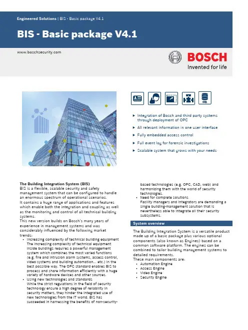
uIntegration of Bosch and third party systems through deployment of OPCu All relevant information in one user interface u Fully embedded access controlu Full event log for forensic investigations uScalable system that grows with your needsThe Building Integration System (BIS)BIS is a flexible, scalable security and safetymanagement system that can be configured to handle an enormous spectrum of operational scenarios.It contains a huge range of applications and features which enable both the integration and coupling as well as the monitoring and control of all technical building systems.This new version builds on Bosch's many years of experience in management systems and was considerably influenced by the following market trends:•Increasing complexity of technical building equipment The increasing complexity of technical equipment inside buildings requires a powerful management system which combines the most varied functions (e.g. fire and intrusion alarm systems, access control,video systems and building automation... etc.) in the best possible way. The OPC standard enables BIS to process and share information efficiently with a huge variety of hardware devices and other sources.•Using new technologies and standardsWhile the strict regulations in the field of security technology ensure a high degree of reliability in security matters, they hinder the integrated use of new technologies from the IT world. BIS hassucceeded in harnessing the benefits of non-security-based technologies (e.g. OPC, CAD, web) and harmonizing them with the world of security technologies.•Need for complete solutionsFacility managers and integrators are demanding a single building-management solution that is nevertheless able to integrate all their security subsystems.System overviewThe Building Integration System is a versatile product made up of a basic package plus various optional components (also known as Engines) based on a common software platform. The engines can becombined to tailor building management systems to detailed requirements.These main components are:•Automation Engine •Access Engine •Video Engine •Security Engine* not available in all countriesThese engines are described in greater detail in separate datasheets.FunctionsSystem architectureThe BIS Engines provide fire and intrusion detection,access control, video surveillance plus the monitoring of HVAC and other vital systems.BIS is based on a performance-optimized multi-tier architecture especially designed for use in Intranet and Internet environments.Subsystems are connected via the well-established,world-wide OPC standard. This open standard makes it easy to insert BIS into existing OPC-compliant subsystems.Optionally, individual BIS systems can cooperate by providing data to, or consuming data from, other BISsystems. The result is a Multi-server BIS system.1. A BIS consumer server with workstations and router in a local area network (LAN)2.Wide area network (WAN)3.BIS provider servers with workstations and routers in local area networks (LAN)Organizational structure and configurationA number of automatic functions and easy-to-use tools make configuration installer-friendly, saving time and expense.Hierarchical location trees can be created by theimport of existing CAD data containing layers, named views and detector locations. Zooming and panning allow rapid navigation through the building.The user interface is web -based using dynamic HTML pages. Default pages for different screen resolutions and formats are included in the installation software,and the default pages can easily be customized using a standard HTML editor.BIS automatically detects the monitor resolution and provides the appropriate user interface.OperationThe system’s main task is to operate as the alarm-monitoring and control center for the various security systems within a site. Its graphical interface isdesigned to help the operator grasp the extent and urgency of an occurrence quickly, and to take promptand effective action.The heart of the system, the State Machine, monitors all incoming events and operator requests and, if desired, can take actions prescribed by user-defined rules or Associations, thus unburdening the operators.System securityAES encryption between BIS central server andworkstations provides additional security in addition to configurable user-access rights. If PCs within a corporate network are to be used as clientworkstations then enhanced security can be achieved by restricting operators to specific workstations or IP-addresses.Basic packageThe Building Integration System basic packageprovides many features used in common by the various Engines.•Customizable device condition counters to provide an overview of the condition of subsystems across the entire BIS system•Message processing and alarm display•Alarm queue with up to 5000 simultaneous alarmevents and detailed alarm information•Fixed assignment of operators to workstations for higher security•State machine for automated event and alarm handling.•Web-server-based platform allows client workstations to connect to BIS via just the Internet Explorer •Direct support for location maps in standardAutoCAD DWF vector format reduces configurationeffort.•Changes to architecture within a graphic (new walls,moving a door, etc.) can be implemented without changing the BIS configuration, simply import a new plot file.•Automated workflows between operators, with message broadcasting and customizable escalation paths•Huge library of standardized detector icons in standard vector format including color, event and control definitions•Direct control and monitoring of detectors via the context menus of their icons in the location maps •Direct control and monitoring of detectors via the logical tree-structure (e.g. building – floor – room) of a site, with hyperlinks to photos, manuals,instructions•Location tree generated automatically from the "named views" within the AutoCAD graphic•Action management for automatic and manual control into connected subsystems and their peripherals•Device overview for all connected subsystems, and their peripherals (detectors) and internal virtual devices (operator, server, ...) in the form of a tree structure with detailed information about address,status, type, location and notes. Control theperipherals via the context menus of their tree nodes.•Ability to compartmentalize the managed site into autonomous Divisions, and to restrict operators to the control of specific Divisions.•Ability to provide specific information to the operator in the form of free-form “miscellaneous” hypertext documents, including text, bitmaps, video images,etc.•Highly configurable operator access rights for monitoring and control of subsystems and their peripherals•Event log to ensure all events are completely documented (including messages received and actions taken)•Reporting services to quickly create reports from the event log•Linking and embedding of OPC servers from any computer in the network •Online HelpAction plans and location mapsBIS amplifies standard alarm-handling by its ability to display action plans and location maps, including graphical navigation and the alarm-dependentvisualization of layers inside those maps. This ensures optimal guidance to operators especially in stress situations, such as fire or intrusion alarms.Alarm-dependent action plans or workflows provide detailed event-dependent information such as standard operating procedures, live images, control buttons, etc. to the operator. Simply create and assign one action plan to each possible alarm type in your system, e.g. fire alarm, access denied, technical alarms, etc.With the deletion of an alarm message an unmodifiable snapshot of the displayed action plan is attached to the event log. This ensures accountability by providing a trace of all steps performed by the operator duringthe alarm response.•Location maps are a visualization of premises e.g.floors, areas or rooms, based on the popular AutoCAD vector-graphics format. Detectors and other devicesare represented by colored, animated icons thatprovide direct control via their context menus. In the case of an alarm the system zooms automatically tothe location in the map where it was triggered.• A location tree provides entry points to the locationmap and its graphical navigation functions (pan,zoom).•Alarm-dependent layer control allows the display ofadditional graphical information for specificsituations, e.g. escape routes in case of fire alarms. BIS optional accessoriesThe optional features listed below can be added to the BIS system to meet specific customer requirements. They are usable with all the BIS Engines (Automation, Access, Video and Security Engine).Alarm management packageThis package extends the standard alarm-handling of your BIS system by some additional features: Message distribution allows the definition of escalation scenarios which are activated automatically when an operator or operator group fails to acknowledge an alarm message within a defined period. BIS will then forward the message automatically to the next authorized operator group. The timer feature allows the setup of time schedules which can be used to perform automatic control commands, such as closing a barrier at 8:00 pm, as well as for time-dependent redirection of alarm messages, e.g. within time period 1 show message tooperator group 1 else to operator group 2.The operator alarm feature allows an operator to trigger an alarm manually from the location tree, for example, if informed by telephone of a dangerous situation. Such manual alarms are processed in the same way as those triggered by a detector: that is, the associated documents are displayed and all steps taken are recorded in the event log.The application launcher allows the invocation of non-BIS applications by the system based upon predefined conditions, e.g. alarms or timers. A typical application of this would be for an automatic, scheduled system backup.Building Integration System in figuresParts includedWhen ordered as Installation Media in Box the box contains:ponents1BIS Installation medium with software and installation manuals as PDF1Quick installation guide (printed)When downloaded (Version 4.0 and later) the online documentation is contained in the download.The basic package includes the following licenses: ponents1Operator client license1Division licenseTechnical specificationsMinimum technical requirements for a login or connection serverMinimum technical requirements for a client computerOrdering informationBIS is available in the following languages:•DE = German•EN = English•ES = Spanish•FR = French•HU = Hungarian•NL = Dutch•PL = Polish•PT = Portuguese•RU = Russian•TR = Turkish•ZH-CN = Simplified Chinese•ZH-TW = Traditional ChineseA BIS basic license is required when setting up a new systemBIS 4.1 Basic LicenseLicense for the use of the software as downloadedfrom the website. No physical parts are delivered andthe user documentation is contained in the download.Order number BIS-BGEN-B41BIS 4.1 Installation Media in BoxBox contains the installation medium for all languagesand the Quick Installation Guide.Order number BIS-GEN-B41-BOXBIS 4.1 Alarm Management PackageLicense for the addition to BIS of the feature specifiedOrder number BIS-FGEN-AMPK41BIS 4.1 additional 1 Operator ClientLicense for the addition to BIS of the feature specifiedOrder number BIS-XGEN-1CLI41BIS 4.1 additional 1 DivisionLicense for the addition to BIS of the feature specifiedOrder number BIS-XGEN-1DIV41BIS 4.1 Multi-Server Connect per ServerLicense for the addition to BIS of the feature specifiedOrder number BIS-FGEN-MSRV41BIS Upgrade from 3.0 to 4.xLicense for an upgrade between the versionsspecified.Order number BIS-BUPG-30TO40BIS Upgrade from 2.x to 4.xLicense for an upgrade between the versionsspecified.Order number BIS-BUPG-2XTO40BIS 4.1 BVMS ConnectivityLicense for the connection between one BIS and oneBVMS installationOrder number BIS-FGEN-BVMS41Represented by:Americas:Europe, Middle East, Africa:Asia-Pacific:China:America Latina:Bosch Security Systems, Inc. 130 Perinton Parkway Fairport, New York, 14450, USA Phone: +1 800 289 0096 Fax: +1 585 223 9180***********************.com Bosch Security Systems B.V.P.O. Box 800025617 BA Eindhoven, The NetherlandsPhone: + 31 40 2577 284Fax: +31 40 2577 330******************************Robert Bosch (SEA) Pte Ltd, SecuritySystems11 Bishan Street 21Singapore 573943Phone: +65 6571 2808Fax: +65 6571 2699*****************************Bosch (Shanghai) Security Systems Ltd.203 Building, No. 333 Fuquan RoadNorth IBPChangning District, Shanghai200335 ChinaPhone +86 21 22181111Fax: +86 21 22182398Robert Bosch Ltda Security Systems DivisionVia Anhanguera, Km 98CEP 13065-900Campinas, Sao Paulo, BrazilPhone: +55 19 2103 2860Fax: +55 19 2103 2862*****************************© Bosch Security Systems 2015 | Data subject to change without notice 181****2875|en,V7,30.Nov2015。
中英文对照:建筑专业词汇(1)管理administer; administration; control; manage; management; superintendence; supervision管理报表managerial report管理报表系统managerial report system管理报告managerial report管理报告系统managerial report system管理操作台administrative operator station管理操作系统management operating system; supervisor operation system;supervisory operating system管理操作员administrative operator管理操作员站administrative operator station管理差距management gap管理程序executive program; executive routine; supervisor; supervisory routine; hypervisor; supervisory program管理程序测试supervisor program test管理程序常驻区域supervisor residant area管理程序的例行程序supervisor routine管理程序的试验程序supervisor test program管理程序的组成executive program components管理程序调入supervisor call管理程序调入码supervisor call code管理程序调入指令supervisor call instruction (SVC)管理程序调用命令supervisor call instruction (SVC)管理程序调用命令中断supervisor call interruption管理程序调用命令子程序supervisor call routine管理程序调用中断supervisor call interruption; supervisor call interrupt 管理程序队列区supervisor queue area管理程序方式supervisor mode管理程序仿真supervisory program simulation管理程序封锁supervisor lock管理程序模拟supervisory program simulation管理程序锁supervisor lock管理程序通信区supervisor communication region 管理程序暂驻区supervisor transient area管理程序中断supervisor interrupt管理程序驻留区supervisor resident area管理程序状态supervisor mode; supervisor state 管理处management管理磁盘hyperdisk管理的任务managerial role管理的作用managerial role管理调用程序supervisor call program管理毒品法令decree of management of narcotic drugs管理对策management game管理范围control limit管理方式supervisor mode管理费cost of operation; management cost; management cost; operation cost; overhead charge; management expenses; costs of administration; overhead expenses管理分析management analysis管理分析报告系统management analysis reporting system管理服务management service; supervisor services管理服务程序supervisor services管理覆盖程序supervisor overlay管理工程administrative engineering; management engineering 管理工作handing operation管理工作间隔的约会块session commitment unit管理工作系统management operating system (MOS)管理工作站management work station管理规划及监督management planning and control管理画面supervisory frame管理环境management environment管理会计management accounting管理机supervisor管理机构administrative agency; administrative organization; administration; administrative authorities管理级别supervisory level管理级计算机management leve computer管理寄存器supervisor register管理计划management planning管理计划系统management planning system管理计算management accounting管理计算机supervisory computer管理键盘supervisory keyboard管理经济managerial economics管理局administration管理决策系统management decision system管理科学management science管理科学工作者management scientist管理控制management control; supervisory control管理控制程序supervisor control program管理控制级management control level管理控制盘supervisory control disk管理控制系统management control system; supervisory control 管理框图法control chart method管理例行程序executive routine; supervisory routine管理良好的well-regulated管理能力supervisory capability管理排队区supervisor queue area管理器supervisor管理请求分程序supervisor request block管理人manager管理人员handling crew; managerial staff; superintendent 管理软件management software管理设备supervisory unit管理时间administrative time管理数据management data管理水平control level; level of control管理顺序supervisory sequence管理所control house; control station管理特许指令supervisor-privileged instruction管理通信宏指令supervisor communication macro管理通信区supervisor communication region管理图control chart管理图表control chart管理土壤资源managing soil resources管理维护实用程序management support utility管理系统management system; managerial system; supervisory system管理系统多道程序设计executive system multiprogramming管理信号supervisory signal管理信息administrative information; management information管理信息系统management information system; management operating system 管理信息要求management information requirement管理性数据处理administrative data processing管理序列supervisory sequence管理学模型management science model管理学院school of management管理训练management training管理研究management research管理羊群running sheep管理业务management service; supervisor services; supervisory service 管理因素management factors管理应用程序包management package管理语句语言control statement language管理员administrator; controller管理支持实用程序management support utility管理指令housekeeping instruction; executive instruction管理中继supervisory relay管理终端office terminal管理终端系统administrative terminal system (ATS)管理专业训练软件management training software 管理转接supervisory relay管理状态controlled state管理子程序supervisory routine合同agreement; stipulation; charter; contract合同更改的请求contract change request合同更改建议contract change proposal合同更改通知书contract change notification合同工jobbing work合同工厂contract plant合同规定contractual specifications合同号contract number合同技术要求contract technical requirements (CTR)合同签定日期contract award date合同饲养contract feeding合同谈判contract negotiation合同条款terms of the contract合同项目contract item合同要求requirement建筑build; architecture; construct; architectural; architectural & industrial ceramics建筑安装工程量construction work quantity 建筑板材building board建筑材料表list of building materials建筑材料检验building material testing 建筑材料行building material dealer建筑材料运输列车construction train建筑草图architectural sketch建筑朝向building orientation建筑成本预算construction cost estimate 建筑承包商building contractor建筑尺度architectural scale建筑处理architectural treatment建筑创作architectural creation建筑大五金architectural metalwork建筑大样architectural detail建筑单元building unit建筑费construction cost建筑风格architectural style建筑辅助系统building subsystem建筑钢construction(al) steel建筑钢板building sheet建筑高度building height; height of building建筑高度分区building height zoning; height zoning建筑工程升降机builder's lift建筑工地选择siting建筑工羊角锤头builder's claw hammer head建筑工业building industry; construction industry建筑工种building trades建筑构思architectural conception建筑构图compostion on architecture; architectural composition 建筑构造building construction建筑估价building cost estimate建筑管理architectural control建筑规程building regulations建筑规范building code建筑机械construction machinery; building machinery建筑及维护规则recommendation建筑结构building structure建筑结构分析语言structural engineering system solver (STRESS) 建筑立面elevation of building; building elevation建筑沥青bitumen for building; building asphalt No. 10建筑力学architectural mechanics建筑铝型材生产线architectural aluminium profile production line 建筑毛面积gross floor area建筑毛造价gross building cost建筑面积area of structure; covered area建筑面积比floor-area ratio (F.A.R.)建筑面积指标floor-space index (F.S.I.)建筑模数building module建筑配景entourage of building建筑平面architectural plane; building plane建筑起重机building crane; construction-site crane 建筑砌块building block建筑气候分区climate region of building建筑青铜architectural bronze建筑青铜合金architectural bronze建筑声学architectural acoustics建筑石paring stone建筑石料building stone建筑时期观念construction period concept建筑史architectural history; history of architecture 建筑收进线building setback line建筑陶板architectural terra-cotta (ATC)建筑陶瓷architectural pottery建筑特色architectural feature建筑体积architectural volume; cubage建筑体积计算cubing建筑体系building system建筑体形building size建筑透视architectural perspective建筑外壳building shell建筑外形architectural appearance建筑物building; structure建筑物保险building insurance建筑物朝向direction of building建筑物基础building foundation建筑物间距distance between buildings建筑物理architectural physics; building physics 建筑物缺隐building deficiency建筑物入口building entrance建筑物租约building lease建筑现场construction建筑限制building restriction建筑限制线building restiction line建筑效果architectural effect建筑型钢轧机机座structural stand建筑型式type of construction; architectural form 建筑遗产architectural heritage建筑艺术architectural art建筑艺术处理artistic treatment in architecture; architectural treatment建筑艺术形式artistic form of architecture建筑用地building lot; building site; lot建筑用地规划plot planning; block planning建筑用钢铁constructional iron建筑用黄铜architectural brass建筑用木材building timber建筑用提升机service-building elevator建筑原理architectonics; architectural principle建筑造型艺术art of architectural modelling建筑占地系数coefficient of land used for buildings建筑障碍architectural barriers建筑照明architectural lighting建筑折旧准备buildings depreciation reserve建筑哲理architectural philosophy建筑柱式architectural orders; orders of architecture建筑装饰architectural decoration; architectural ornament建筑装饰彩釉砂涂料colour-glazed sand paint for building decoration 建筑装饰学architectural decoration建筑装修五金architectural metalwork建筑自动化building automation建筑自重structural weight per square meter建筑渲染architectural rendering; rendu进度progress; tempo进度安排scheduling进度报表progress report; progress sheet进度报告制度progress reporting system进度工作日程progress schedule进度估计progress estimate进度管理progress control; schedule control 进度计划scheduled plan进度计划安排scheduling进度计划表schedule diagram进度计划明细表detailed schedule进度计划总表master schedule进度检查follow-up进度控制schedule control; progress control进度时间表process schedule进度图progress chart; progress map进度维护scheduled maintenance进度照片photographs of progress施工construct; execution; construction; execution of works施工安装图construction and erection drawing施工安装用的机械及工具machines and tools for construction and erection 施工标桩construction stake施工布置图construction plan施工步骤construction procedure; construction steps施工测量construction survey施工程序construction program; execution programme for works施工程序网络图project network施工贷款construction loan施工单位construction organization; builder施工道路construction road施工地点job location施工吊车construction hoist施工定额construction norm施工队construction team施工方法job practice施工方式form of construction work施工费用construction cost施工缝construction joint施工工程construction work施工工程师construction engineer; operating engineer 施工工程学construction engineering施工工期construction period施工工种construction trade施工规模scope of construction item; size of construction施工荷载construction loads; working load施工合同construction contract施工机械construction machinery施工机械费cost of constructor's mechanical plant施工机械化mechanization of building operation; mechanization of construction施工机械化系数coefficient of construction mechanization施工技术财务计划financial plan for construction technology施工计划construction plan; construction program(me)施工监督supervision of construction; supervision; monitoring施工检查inspection of construction施工检查员construction inspector施工阶段construction stage; construction phase施工进度construction progress施工进度表schedule of construction; schedule of operations; work-schedule 施工进度计划detailed construction schedule; construction schedule施工经济学construction economics施工经理construction manager施工经验construction experience施工卷扬机builder's hoist; builder's winch施工临时螺栓construction bolt施工流水作业法construction streamline method 施工面积floor space under construction施工平面图construction plan施工期construction period施工起重机construction hoist施工企业construction enterprises施工前阶段preconstruction stage施工区construction area施工缺陷constructional deficiency施工设备plant for construction; construction equipment施工设计detail design; detailed engineering施工水平仪builder's level施工说明general des cription of construction施工说明书construction specifications施工图设计construction documents design施工图设计阶段construction documents design phase; construction documents phase施工图预算working drawing estimate施工文件construction documents (包括施工图及说明)施工现场fabricating yard; job location施工详图detail of construction; construction detail; working drawing 施工项目project under construction; construction item施工项目编号construction item reference number施工效率efficiency of construction施工性能workability施工许可证builder's licence施工验收技术规范technical code for work and acceptance施工依据manufacture bases施工营业执照builder's licence施工预算construction estimate施工执照building permit施工准备preliminary work for construction; preparations for construction 施工准备计划preparatory plan施工总平面图overall construction site plan施工总则general conditions of construction施工组织设计construction management plan施工作业计划work element construction program现场field engineering; job site; site; scene (FE)现场安装field mounted (FM)现场安装工作on-site installation work现场安装和维修条件installation and maintenance conditions at field 现场安装螺栓field bolting; field bolt现场安装容器field assembly of vessels现场操作规范field-work standards现场抽查spot checking现场淬火field quenching现场存货field warehousing现场的local现场电视监测生产法television-monitored production现场调查field investigation; field survey; spot investigation; field method; spot survey; (spot) field investigation现场调查设计field survey design现场调查员field worker现场调度spot dispatch现场发泡foam-in-place现场仿真field simulation现场访问facility visit现场工作field work现场管理field management; worksite management现场灌注球基桩franki pile现场焊接field weld; site weld; site welding; field welding 现场核查on-site verification现场核数员field auditor现场计数field enumeration现场计算field calculation现场记录record on spot现场加工field processing现场检查on-site inspection; on-spot check; spot checking现场检验field inspection; on-site inspection; floor inspection; spot inspection 现场交货delivery on the spot; ex works现场交货价格ex point of origin现场交通site traffic现场浇铸cast-in-place现场浇筑cast in situs现场接线field connection现场经纪floor broker; pit broker现场决标award at tender opening现场勘测site survey现场勘察on-the-spot investigation现场可变只读存储器field alterable ROM 现场可更换部件field-replaceable unit 现场客floor trader现场控制台field control station现场联结field connection现场录音live recording现场铆钉对接接头site riveted butt joint 现场铆接field rivet(t)ing; site rivet(ing) 现场配料field mix现场平衡法field balancing technique 现场清洗in-place cleaning现场人员训练field personnel training 现场摄像机field camera; live camera现场设备field apparatus现场生产性能测定on-farm performance 现场实习workshop practice现场实验field experiment现场使用field service; field usage现场使用可靠性on-the-job dependability现场试验field experiment; field test; field investigation; field trial; site test; site trial; on-the-spot experiment现场试验程序field test procedures现场手册field manual现场数据field data现场栓接field bolted现场踏勘reconnaissance trip现场统计field statistics现场维修field maintenance; on-site repair 现场修理current repair; spot repair现场研究field study现场以外的训练vestibule training现场用压缩机field service compressor现场制造field manufacturing现场制作field fabrication; fabrication on site 现场装配field connection现场组装field assembly现场总线fieldbus现场可替换单元LRU [现场的on-site [现场冷却spot cooling [现场冷却;局部冷却spot cooling项目subject of entry; item项目报告project paper项目编制阶段project preparation phase项目标记project mark项目财务估价project financial evaluation项目采购project purchasing项目成本project cost; item cost项目筹备融通资金project preparation facility (PPF)项目贷款project finance; project-financing loan; project loan 项目单menu项目的拟订project formulation项目的所有者owner of the project项目的总投标价值total tender value of project项目发展周期project development cycle项目范围scope of project项目方案project alternatives项目分隔符item separation symbol项目分类classification of items项目分配allocation of items项目分析item analysis项目工程师project engineer项目工程师负责制project engineer system项目管理project management项目管理人project manager项目号item number项目核对法check list (市场调查技术之一)项目核准权projects approval authority项目后评价post project evaluation项目后评价和后继行动post project evaluation and followup 项目划分segregation of items项目化组织projectized organization项目环境生态评价environmental appraisal of a project 项目货款额度project line项目技术评价project technology evaluation项目计划project plan项目计划设计图project planning chart项目记录item record项目加权item weighting项目检验回归曲线item-test regression curve项目建设费用cost of project implementation项目建设进度表project implementation scheduling项目建议书proposals for the projects项目经济估价project economic evaluation; economic evaluation of a project项目经理project manager项目矩阵组织project matrix organization项目控制project control项目块entry block项目历史history of project项目目标管理project management by objectives项目拟订project formulation项目匹配法matching item项目评估project appraisal; project evaluation项目评估法Project Evaluation and Review Technique项目企业经济评价enterprise's economic appraisal of a project 项目删除deletion of items项目上端item top项目社会评价project's social value appraisal项目设备project equipment项目设计item design项目设计工程师负责制project engineer responsibility system 项目生产project production项目说明item des cription项目说明书specification of an item项目投资时期investment phase of a project项目图与布置图project charts and layouts项目网络法project network technique项目网络分析project network analysis项目文件item file项目小组project group; project team organiztion 项目行item line项目修理通知单item repairing order项目选择project selection项目训练法project training项目研究编目item study listing项目研究小组project team项目一次采购法project purchasing项目一览表itemized schedule项目预算program budget; project budget项目预算编制program budgeting项目政治评价political appraisal of a project项目支助业务project supporting services项目执行project implementation项目执行情况审计报告project performance audity report (PPAR) 项目指标project indicators项目转移item advance项目资金筹措project financing质量grade; mass; quality; qualitative properties; mass (物理用语)质量百分比mass percent质量半径关系mass-radius relation质量保持率quality retention质量保证quality assurance质量保证技术出版物quality assurance technical publications 质量保证计划quality control system质量保证控制程序quality assurance operating procedure质量保证手册quality control (assurrance) manual。
建筑工程施工管理英文文献Construction Project Management in the Field of Architecture: An OverviewIntroductionIn the realm of architecture, effective construction project management is crucial for ensuring the successful completion of projects. This article aims to provide an overview of construction project management in the field of architecture, exploring key concepts, methodologies, and best practices.1. Definition and Importance of Construction Project ManagementConstruction project management refers to the planning, coordination, and control of a project from inception to completion. It involves various tasks, such as organizing resources, managing budgets, scheduling timelines, and ensuring quality control. The role of a construction project manager is pivotal in driving the project towards success while simultaneously navigating challenges and mitigating risks.2. Key Components of Construction Project Management2.1 Project InitiationThe project initiation phase involves defining project goals, determining feasibility, and establishing the project scope. During this stage, a project manager identifies key stakeholders, assesses available resources, and prepares a preliminary budget and schedule.2.2 Planning and DesignIn the planning and design phase, the project manager collaborates with architects, engineers, and other experts to develop detailed blueprints, technical drawings, and specifications. This phase also includes obtaining necessary permits and approvals, conducting site surveys, and outlining construction methodologies.2.3 Procurement and Resource ManagementEfficient procurement and resource management are vital aspects of construction project management. This involves sourcing materials, equipment, and labor, while ensuring cost-effectiveness, quality assurance, and adherence to project schedules. Effective communication and negotiation skills are essential in establishing partnerships with suppliers, contractors, and subcontractors.2.4 Construction and ExecutionThe construction and execution phase involves overseeing and coordinating the actual construction process. A project manager must monitor progress, enforce safety protocols, manage change orders, and address any unexpected issues that arise onsite. Regular site inspections, progress reports, and communication with the project team are essential during this stage.2.5 Risk Management and Quality ControlConstruction projects are inherently subject to risks, such as delays, budget overruns, and safety hazards. A skilled project manager implements risk management strategies to identify potential risks, develop contingency plans, and mitigate their impact. Additionally, ensuring quality controlthroughout the construction process is crucial to achieving a satisfactory result.2.6 Project CloseoutThe project closeout phase involves final inspections, ensuring regulatory compliance, and coordinating the handover of the completed project to the client. Documentation of warranties, as-built drawings, and operation manuals are also essential components of closing out a construction project.3. Best Practices in Construction Project Management3.1 Effective CommunicationClear and timely communication is a fundamental factor in successful construction project management. A project manager must establish open lines of communication among all stakeholders, fostering collaboration, addressing concerns, and ensuring that objectives are effectively shared.3.2 Comprehensive Project DocumentationMaintaining accurate and detailed project documentation is crucial throughout the entire construction process. This includes contracts, permits, change orders, progress reports, and meeting minutes. Well-organized documentation facilitates smooth communication, aids in dispute resolution, and forms a valuable resource for future reference.3.3 Regular Monitoring and ReportingRegular monitoring of project progress is essential for identifying issues, tracking milestones, and evaluating the project's overall performance.Timely reporting allows for effective decision-making, enables proactive risk management, and ensures that project goals are being met.3.4 Embracing TechnologyThe use of advanced construction project management software and tools can significantly enhance project efficiency. These tools aid in scheduling, budgeting, collaboration, and data analysis, providing real-time insights and facilitating informed decision-making.ConclusionConstruction project management is a critical aspect of successful architecture projects. Through effective planning, coordination, and control, project managers navigate challenges, ensure timely completion, and deliver high-quality results. By adhering to best practices and utilizing cutting-edge tools, the field of construction project management continues to evolve, contributing to the growth and success of the architectural industry.。

建筑工程专业英语词汇(1) 建设,建筑,修建 to build, to construct建筑学 architecture修筑,建筑物 building房子 house摩天大楼 skyscraper公寓楼 block of flats (美作:apartment block) 纪念碑 monument宫殿 palace庙宇 temple皇宫,教堂 basilica大教堂 cathedral教堂 church塔,塔楼 tower十层办公大楼 ten-storey office block柱 column柱列 colonnade拱 arch市政 town planning (美作:city planning)营建许可证,建筑开工许可证 building permission绿地 greenbelt建筑物地三面图 elevation设计图 plan比例尺 scale预制 to prefabricate挖土,掘土 excavation基 foundations, base, subgrade打地基 to lay the foundations砌好地砖列 course of bricks脚手架 scaffold, scaffolding质量合格证书 certification of fitness原材料 raw material底板 bottom plate垫层 cushion侧壁 sidewall中心线 center line条形基础 strip footing附件 accessories型钢 profile steel钢板 steel plate熔渣 slag飞溅 welding spatter定位焊 tacking引弧 generating of arc熄弧 quenching of arc 建筑工程专业英语词汇(2) 充水实验 filling water test错边量 unfitness of butt joint底圈 foundation ring真空度检漏 vacuum degree leak test丁字焊缝 tee welding渗透探伤 oil whiting test充水实验 filling water test内侧角焊缝接头 interior angle welding line joint基础沉降 foundation settlement测量基准点 datum mark稳定性实验 stability test排气阀 outlet valve角钢 angle steel构件 component part机械损伤 mechanical damage缩孔 shrinkage cavity折迭 enfoldment碳钢管 carbon steel tube公称直径 nominal diameter预埋件 embedded part轴测图 axonometric drawing布置图 arrangement diagram氧乙炔气割 oxyacetylene gas cutting低合金钢管 low alloy steel热影响区 heat affected area修磨 polish砂轮片 grinding wheel等离子 plasma panel重皮 coldlap凹凸 unevenness缩口 necking down端面 head face倾斜偏差 dip deviation外径 external diameter砂轮 grinding wheel管件 pipe casting单线图 single line drawing平齐 parallel and level两端 two terminals满扣 buckle螺栓紧固 bolton周边 periphery附加应力 additional stress同轴度 axiality平行度 parallelism随机 stochastic允许偏差 allowable variation重直度verticality焊道 welding bead坡口 beveled edges外观检查 visual inspection重皮 double-skin水平方向弧度 radian in horizontal direction 成型 molding直线度 straightness accuracy焊缝角变形 welding line angular distortion 水平度 levelness铅垂度 verticality翘曲变形 buckling deformation角尺 angle square对接焊缝 butt weld母材 parent metal法兰密封面 flange sealing surface夹层 interlayer表面锈蚀浓度 surface corrosion concentration挠曲变 bending deformation超声波探伤 ultrasonic testing/ ultrasonic examination压力容器 pressure vessel预制下料 prefabrication baiting排版直径 set-type diameter焊缝 welding line中幅板 center plate测量方法 measuring method基准点 datum mark跳焊 skip welding允许偏差 allowable variation补强板 stiffening plate开孔 tapping对接接头 banjo fixing butt jointing角钢 angle iron安装基准圆 installation fundamental circle 吊装立柱 hoisting upright column焊接钢管 welded steel pipe向心斜拉筋 centripetal canting pull rope带板 band plate槽钢胀圈 channel steel expansion ring环口 collar extension局部变形 local distortion环缝 circumferential weld顶板 top plate拱顶 vault顶板加强肋 stiffening rib 水平度 levelness隔离盲板 blind plate氩弧焊argon arc welding压盖螺栓 gland bolt间距 spacing有效期 period of validity担任 take charge of undertake焊条 welding rod碳钢焊条 carbon steel焊丝 welding wire熔化焊 melting钢丝 steel wire气体保护焊 gas shielded arc welding烘干 drying清洗 ablution制度s ystem焊接工艺 welding procedure相应 corresponding手工电弧焊 manual electric arc welding手工钨极 manual tungsten electrode打底 render电源 power source交流 alternating current焊件 weldment管壁厚度 pipe thickness对接焊缝 butt weld工件壁厚 workpiece飞溅物 splash沾污 smirch油污 oil stain细锉 smooth file铣刀 milling cutter氧化膜 oxide film脱脂处理 ungrease treatment]棉质纤维 cotton fibre丙酮 acetone硫 sulfur焊剂 welding flux钢板 steel plate纵向焊缝 longitudinal weld longitudinal seam 筒节 shell ring封头 end socket卷管 reelpipe强度实验 strength test起弧 arc starting穿堂风 draught熔合 fusion反面 reverse side整体 integral封堵 block up焊口 weld bond对接 butt joint胎具 clamping fixture卷板机 plate bending rolls中心支架 center bearing bracket椭圆度 ovality等分线 bisectrix搭接宽度 lap width点焊 spot welding搭接焊 overlap welding对称 symmetrically螺旋爬梯 cockle stairs放料阀 baiting valve液位计 content gauge芬兰维萨拉 V ailsla OY美国美科 "Met-coil, USA"集中式空调系统 centralized air conditioning system裙房 annex热源 heat source平面位置地空间 space of planimetric position密封性能 sealing performance机房 machine room节点 timing专业专业 "profession or discipline 都可以,要根据上下文"连体法兰 coupling flange垂直井笼 vertical well cage变风量 variable air rate施工面展开 construction unfolds违约行为 noncompliance合同交底- contract presentation管理承包商 Management Contractor party 工程量 work amount实施地形象进度 progress of implementation 完工资料 as-built documentation文整 clear-up审核 review汽车式起重机 Autocrane深化图纸 deepen drawing设备配置计划 equipment furnishment plan 结构预埋配合阶段 Structure pre-embedment assistancestage精装修阶段 Fine fitment stage工程施工阶段 Construction stage 医用胶布 medical proof fabric高频 high frequency焊炬 welding torch建筑工程专业英语词汇翻译(4)综合分析判断 comprehensive analysis and judgement变压器 transformer抽芯loose core过道 aisle三相电容 three phase capacitance芯棒 core rod都市规划与土地开发 Urban g and Land Development社区开发及工业区开发Community Development and Industry Park Development开发许可申请 Development Permit土地使用变更计划 Land Use Rezoning Plan 主要计划及细部计划主要计划及细部计划Master Plan and Detail Plan都市计划更新计划 Urban Renewal Plan都市设施 Urban Design建筑设施 Architecture Design大地工程 Geotechnical Engineering工址调查 Site Investigation现地实验与室内实验现地实验与室内实验In-Situ and Laboratory Test基础工程 Foundation Design深开挖工程及建物保护深开挖工程及建物保护Deep Excavation and Building Protection新生地及软弱地层改良 Reclamation and Soft Ground Improvement山坡地开发与水土保持 Slope land Development, Soil and Water Conservation潜盾隧道与岩石隧道 Shield Tunnel and Rock Tunnel大地工程施工顾问大地工程施工顾问Geotechnical Construction Consultant土壤材料实验 Soil and Material结构工程 Structural Engineering各类钢筋混凝土、预力混凝土、钢结构及钢骨钢筋混凝土结构 Structures of R.C., Prestressed Concrete, Steel, and SRC桥梁、高层建筑、地下结构物、隧道、深开挖挡土结构 Bridges, High-Rise Buildings, Underground Structures, Tunnels, Retaining Structures for Deep Excavations桥梁安全检测、评估及维修补强 Bridge Inspection, Assessment, and Rehabilitation钢结构细部设计及制造图 Steel Structural Detail Design and Shop Drawings工程竣工阶段 Completion stage台钻 Bench drill冲击钻 Churn drill手电钻 Electric portable drill砂轮切割机 Abrasive cutting off machine角钢卷圆机 Angle iron rolling machine管道切断器 Pipe cutting machine铜管调直机 Copper pipe straighteningmachine管道压槽机管道压槽机 Book joint setting machine forpipes管道压槽机管道压槽机 Book joint setting machine forpipes角向磨光机 Angle polishing machine电动套丝机 Electric threading machine电动卷扬机 Electric winch电动试压泵 Motor-driven pressure test pump手动试压泵 Manual pressure test pump阀门试压机 Valve pressure test device阀门试压机 Valve pressure test deviceTDC(F)风管加工流水线 TDC(F)airductwork fabricationstream line等离子切割机 Plasma cutting machineTDC(F)法兰条成型机法兰条成型机 TDC(F) flange stripshaping mill勾码成型机 Forming machine for flange clampTDC(F)风管加工成型机 TDC(F) ductfabrication shaping mill多普勒超声波流量检测仪 Dopplerultrasonic flow detector温、湿度传感器 "Temperature, humidity senor"精密声级计 Precision sound level meter风管漏风量测试仪、风室式漏风测试装置风管漏风量测试仪、风室式漏风测试装置"Duct air leakagetester, airchamber air leakage testing device"风罩式风量测试仪 Air hood air rate tester微压计、毕托管、热球(电)风速仪 "Micromanometer ,pitot tube, hot bulb(electrical) anemoscope"潜水泵 Submerged pump电动弯管机 Electric pipe bender铜管弯管机 Copper pipe bender 厂房工程 Industrial Plant工业厂房-石化工厂、钢厂、电厂、气体厂、科技工业厂房、一般性厂房 Industrial Plants--Petroleum and Chemical, Steel, Power, Gas, High-Technical and General Plants环保设施工厂-垃圾焚化厂、垃圾掩埋场、污水处理厂及相关管线 Environment Protecting Plants--Incineration Plants, Garbage Disposal Plants, Waste Water Treatment Plantsand Piping System设备支撑结构、管架、操作平台 Equipment Supporting Structures, Pipe Racks, Operating Platforms设备基础 Equipment Foundations厂区一般土木及公共设施 General Civil Works and Utilities of Plants运输工程 Transportation Engineering运输规划 Transportation Planning停车场设施工程规划、设计 Engineering Planning & Design for Parking Facilities建筑交通维持计划 Traffic Control & Management during Construction水利及港湾工程 Hydraulic and Harbor Engineering营建管理 Construction Management估价及工程预算制作 Estimates and Engineering Budget Works营建管理 Construction Management工程监造 Construction Supervision施工计划 Construction Plan工程进度控管 Schedule Control during Construction施工规划 Construction Specifications环境工程 Environmental Engineering环境影响评估 Environment Impact Assessment环境监测 Environmental Monitoring地下水监测系统 Groundwater Monitoring污水处理厂 Wastewater Treatment Plant污水下水道 Sewage System噪音振动防治 Noise and Vibration垃圾焚化厂兴建工程 Waste Incinerator废弃物处理系统工程 Waste Treatment & Disposal共同管道 Common Ducts管道及附属设施之规划设计 Planning and Design of Common Ducts Structures and Subsidiary Facilities经济效益分析 Economic and Efficiency Analysis财务评估 Financial Evaluation管理维护办法及组织订定管理维护办法及组织订定Regulation for the Management, Maintenance and Organization液压弯管机 Hydraulic pipe bender电动剪刀 Electric clipper液压铆钉钳 Hydraulic riveting clamp线槽电锯 Trunking electric saw开孔器 Tapper电动空压机 Electric air compressor液压千斤顶 Hydraulic jack液压手推车 Hydraulic trolley焊条烘干箱 Welding rod drying box手拉葫芦 Chain block道(垫)木 Sleeper转速表 Tachometer电流钳型表 Clip-style ammeter压力表 Pressure gauge接地电阻测试仪接地电阻测试仪 Earthing resistance testing device氧气表 Oxygen gauge乙炔表 Acetylene gauge对讲机 Walkie talkie文件和资料 documents and information?建设单位 Construction unit安装单位 Installation unitz建筑工程专业英语词汇翻译(3) 送气 air supply电流衰减装置 current attenuation气体延时保护装置 time delay熄弧 quenching of arc成型 molding钢印代号 steel seal质量分析 quality analysis负责人 principal审批 examine and approve补焊工艺 repair welding压缩机 compression pump平焊法兰 welded flange测试流程图 test flow chart加固措施 reinforcement measure校验 verify升压 boost pressure读数 off scale reading满刻度值 full-scale value盲板 blind plate压力表 pressure meter强度 intensity目测 eye survey, visiual inspection半径 radius电力复合脂 electric force compounded grease 电缆敷设 cable laying电缆槽架 cable channel主干线 trunk line弯头 angle fitting剥落处 exfoliation银粉 aluminum powder支持点 support point拆装 disassembly and assembly畅通 smooth电压等级 electric pressure通断实验 onoff终端头 terminals余度 remaining标记牌 notice plate表册 statistical forms电缆桥架 cable testing bridge电机 electric machine相对湿度 relative humidity杂物 sundries耐压实验 withstand voltage test照明器具 ligthing paraphernalia铭牌 nameplate验收规范 acceptance specification接线 wire splice试运 test run进线口 incoming line带电 electrified盘车转子 jigger rotor二次回路 secondary circuit中心线 center line触头 contactor配电 power distribution成套 whole set楼板 floor slab备件 duplicate part, spare part包装 packing器材 equipment导线 conducting wire脱落 fall off规范 specification电器 electrical appliance断路器 line breaker机械联锁 mechanical interlocking碰撞 collision公式 formula轻便 portable 管路 pipeline严密性 leakproofness导电膏 conductive paste压接 compression joint地上连接 overground埋深 buried depth接地线 earth wire说明 description分线盒 junction box接地装置 earthing deivce交叉across塑料保护管 protection tube塑料带 plastic tape防腐处理 preservative treatment接地极 earthing pole接地电阻测试 earth resistance防雷接地 lightning protection遵守 comply with避雷网 lightning conduction引下线 down lead搭接焊 overlap welding避雷针 lightning rod镀锌制品 zinc coating断接卡 breaking of contact电阻 resistance配电装置 power distribution equipment集中接地装置 centralized串联 cascade connection干线联接 main line并列 paratactic单独 solely机组 machine set。
vie架构协议控制英文表述1. Introduction to the Vie Architecture Protocol ControlThe Vie Architecture Protocol Control is a protocol that is designed to ensure efficient management and control of the Vie architecture. This protocol ensures the seamless communication and coordination between various components and modules within the Vie system. It defines the rules and procedures for exchanging information, establishing connections, and managing the flow of data within the system.2. Protocol StructureThe Vie Architecture Protocol Control consists of several layers that work together to enable smooth communication within the system. These layers include the application layer, transport layer, network layer, and data link layer. Each layer has its own set of protocols and functions that contribute to the overall control and coordination of the system.3. Application LayerThe application layer of the Vie Architecture Protocol Control is responsible for managing the high-level communication requirements of the system. It provides the interface for applications and services to exchange data and interact with the system. This layer utilizes protocols such as HTTP, FTP, and SMTP to ensure the efficient transfer and processing of data.4. Transport LayerThe transport layer is responsible for establishing reliable and efficient end-to-end connections between network hosts within the system. It ensures that data is delivered reliably and in the correct order. The transport layer uses protocols such as TCP and UDP to facilitate the transfer of data between applications and services.5. Network LayerThe network layer is responsible for routing and forwarding data packets between different network hosts within the system. It determines the best path for data transmission and ensures that packets are delivered to the correct destination. The network layer utilizes protocols such as IP and ICMP to accomplish these tasks.6. Data Link LayerThe data link layer is responsible for the physical transmission of data across the network. It handles tasks such as framing, error detection, and flow control. The data link layer uses protocols such as Ethernet and Wi-Fi to establish a reliable and efficient link between network hosts.7. ConclusionThe Vie Architecture Protocol Control is a comprehensive set of protocols that enable efficient management and control of the Vie architecture. It ensures seamless communication between various components within the system and establishes reliable and efficient connections for data transfer. The protocol structure, consisting ofthe application layer, transport layer, network layer, and data link layer, provides a robust framework for the control and coordination of the system.。
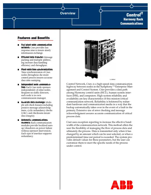
Features and Benefits Overview Control ITHarmony RackCommunications Control Network, Cnet, is a high-speed data communicationhighway between nodes in the Symphony™ Enterprise Man-agement and Control System. Cnet provides a data pathamong Harmony control units (HCU), human system inter-faces (HSI), and computers. High system reliability andavailability are key characteristics of this mission-criticalcommunication network. Reliability is bolstered by redun-dant hardware and communication media in a way that thebackup automatically takes over in the event of a fault in theprimary. Extensive use of error checking and messageacknowledgment assures accurate communication of criticalprocess data.Cnet uses exception reporting to increase the effective band-width of the communication network. This method offers theuser the flexibility of managing the flow of process data andultimately the process. Data is transmitted only when it haschanged by an amount which can be user selected, or when apredetermined time-out period is exceeded. The system pro-vides default values for these parameters, but the user cancustomize them to meet the specific needs of the processunder control.TC00895A■Fast plant-wide communication network: Cnet provides fastresponse time to insure timelyinformation exchange.■Efficient data transfer: Message packing and multiple address-ing increase data handlingefficiency and throughput.■Plant-wide time synchronization: Time synchronization of Cnetnodes throughout the entirecontrol process insures accuratedata time-stamping.■Independent node communica-tion: Each Cnet node operatesindependently of other nodes.Requires no traffic directors;each node is its owncommunication manager.■Accurate data exchange: Multi-ple self-check features including positive message acknowledg-ment, cyclic redundancy checks(CRC), and checksums insuredata integrity.■Automatic communications recovery: Rack communicationmodules provide localized start-up/shutdown on power failurewithout operator intervention.Each type of interface supportsredundancy.Harmony Rack CommunicationsOverviewHarmony rack communications encompasses various communication interfaces as shown inFigure1: Cnet-to-Cnet communication, Cnet-to-HCU communication, and Cnet-to-computercommunication.Figure 1. Harmony Rack Communications ArchitectureThe communication interface units transfer exception reports and system data, control, and con-figuration messages over Cnet. Exception reported data appears as dynamic values, alarms, and state changes on displays and in reports generated by human system interfaces and other system nodes. Exception reporting is automatic at the Harmony controller level. Specifically, the control-ler generates an exception report periodically to update data, after a process point reaches adefined alarm limit or changes state, or after a significant change in value occurs.Harmony Rack Communications Control NetworkCnet is a unidirectional, high speed serial data network that operates at a 10-megahertz or two-megahertz communication rate. It supports a central network with up to 250 system node connec-tions. Multiple satellite networks can link to the central network. Each satellite network supports up to 250 system node connections. Interfacing a maximum number of satellite networks gives a system capacity of over 62,000 nodes.On the central network, a node can be a bridge to a satellite network, a Harmony control unit, a human system interface, or a computer, each connected through a Cnet communication interface.On a satellite network, a node can be a bridge to the central network, a Harmony control unit, a human system interface, or a computer.Harmony Control UnitThe Harmony control unit is the fundamental control node of the Symphony system. It connects to Cnet through a Cnet-to-HCU interface. The HCU cabinet contains the Harmony controllers and input/output devices. The actual process control and management takes place at this level. HCU connection to Cnet enables Harmony controllers to:■Communicate field input values and states for process monitoring and control.■Communicate configuration parameters that determine the operation of functions such asalarming, trending, and logging on a human system interface.■Receive control instructions from a human system interface to adjust process field outputs.■Provide feedback to plant personnel of actual output changes.Human System InterfaceA human system interface such as a Signature Series workstation running Maestro or ConductorSeries software provides the ability to monitor and control plant operations from a single point. It connects to Cnet through a Cnet-to-computer interface. The number of workstations in a Sym-phony system varies and depends on the overall control plan and size of a plant. The workstation connection to Cnet gives plant personnel access to dynamic plant-wide process information, and enables monitoring, tuning, and control of an entire plant process from workstation color graphics displays and a pushbutton keyboard.ComputerA computer can access Cnet for data acquisition, system configuration, and process control. It con-nects to Cnet through a Cnet-to-computer interface. The computer connection to Cnet enablesplant personnel, for example, to develop and maintain control configurations, manage the system database, and create HSI displays remotely using Composer™engineering tools. There are addi-tional Composer and Performer series tools and applications that can access plant informationthrough a Cnet-to-computer interface.Cnet-to-Cnet Communication InterfaceThe Cnet-to-Cnet interfaces are the INIIR01 Remote Interface and the INIIL02 Local Interface.Figure2 shows the remote interface and Figure 3 shows the local interface.Harmony Rack CommunicationsFigure 2. Cnet-to-Cnet Remote Interface (INIIR01)Figure 3. Cnet-to-Cnet Local Interface (INIIL02)Harmony Rack Communications INIIR01 Remote InterfaceThe INIIR01 Remote Interface consists of the INNIS01 Network Interface Module and the INIIT12 Remote Transfer Module (Fig.2). This interface is a node on a central network that can communi-cate to an interface node on a remote satellite network. In this arrangement, two interfaces arerequired: one for the central network, and the other for the satellite network. Bidirectional commu-nication from the central network to the remote satellite network is through standard RS-232-Cports.The remote interface supports hardware redundancy. Redundancy requires a full set of duplicate modules (two INNIS01 modules and two INIIT12 modules on each network). The secondaryINIIT12 module continuously monitors the primary over dedicated Controlway. A failover occurs when the secondary module detects a primary module failure. When this happens, the secondary interface takes over and the primary interface is taken offline.INIIL02 Local InterfaceThe INIIL02 Local Interface consists of two INNIS01 Network Interface modules and the INIIT03 Local Transfer Module (Fig.3). This interface acts as a bridge between two local Cnets. One of the INNIS01 modules operates on the central network side and the other operates on the satellite net-work side. Bidirectional communication from the central network to the local satellite network is through cable connection to the NTCL01 termination unit. The maximum distance betweentermination units on the two communication networks is 45.8 meters (150feet).The local interface supports hardware redundancy. Redundancy requires a full set of duplicatemodules (four INNIS01 modules and two INIIT03 modules). The secondary INIIT03 module con-tinuously monitors the primary over dedicated Controlway. A failover occurs when the secondary detects a primary module failure. When this happens, the secondary assumes responsibility and the primary is taken offline.Cnet-to-HCU Communication InterfaceThe Harmony control unit interface consists of the INNIS01 Network Interface Module and the INNPM12 or INNPM11 Network Processing Module (Fig. 4). This interface can be used for a node on the central network or on a satellite network (Fig.1). Through this interface the Harmony con-trol unit has access to Cnet and to Controlway at the same time. Controlway is an internal cabinet communication bus between Harmony rack controllers and the communication interfacemodules.The HCU interface supports hardware redundancy. Redundancy requires a full set of duplicate modules (two INNIS01 modules and two INNPM12 or INNPM11 modules). The secondary net-work processing module (INNPM12 or INNPM11) continuously monitors the primary through a direct ribbon cable connection. A failover occurs when the secondary detects a primary module failure. When this happens, the secondary assumes responsibility and the primary is taken offline. Cnet-to-Computer Communication InterfaceThe Cnet-to-computer interfaces are the INICI03 and INICI12 interfaces. The INICI03 interfaceconsists of the INNIS01 Network Interface Module, the INICT03A Computer Transfer Module,and the IMMPI01 Multifunction Processor Interface Module (Fig. 5). The INICI12 interface con-sists of the INNIS01 Network Interface Module and the INICT12 Computer Transfer Module(Fig6).Harmony Rack CommunicationsFigure 4. Cnet-to-HCU InterfaceFigure 5. Cnet-to-Computer Interface (INICI03)Figure 6. Cnet-to-Computer Interface (INICI12)Harmony Rack CommunicationsA computer interface can be used for a node on the central network or on a satellite network (Fig.1). It gives a host computer access to point data over Cnet. The computer connects through either an RS-232-C serial link at rates up to 19.2 kilobaud or through a SCSI parallel port when using an INICI03 interface. The computer connects through an RS-232-C serial link at rates up to 19.2 kilobaud when using an INICI12 interface. Each interface is command driven through soft-ware on the host computer. It receives a command from the host computer, executes it, then replies to the host computer.Note: A workstation running Conductor VMS software does not use an INICI03 or INICI12 Cnet-to-Computer Interface but instead has its own dedicated version of the Cnet-to-computer interface (IIMCP02 and IIMLM01).Communication ModulesTable 1 lists the available Harmony rack communication modules. These modules, in certain combinations, create the various Cnet communication interfaces.Network Interface ModuleThe INNIS01 Network Interface Module is the front end for all the different Cnet communication interfaces. It is the intelligent link between a node and Cnet. The INNIS01 module works in con-junction with the transfer modules and the network processing module. This allows any node to communicate with any other node within the Symphony system.The INNIS01 module is a single printed circuit board that occupies one slot in the module mount-ing unit (MMU). The circuit board contains microprocessor based communication circuitry that enables it to directly communicate with the transfer modules and network processing module, and to interface to Cnet.The INNIS01 module connects to its Cnet communication network through a cable connected to an NTCL01 termination unit. Communication between nodes is through coaxial or twinaxial cables that connect to the termination units on each node.Cnet-to-Cnet Remote Transfer ModuleThe INIIT12 Remote Transfer Module supports bidirectional communication through twoRS-232-C ports. Port one passes system data only. Port two passes system data or can be used as a diagnostic port. The central network INIIT12 module can use a variety of means to link to the sat-ellite network INIIT12 module such as modems, microwave, and transceivers. The INIIT12Table 1. Harmony Rack Communication Modules ModuleDescription Cnet-to-Cnet Cnet-to-HCU Cnet-to-Computer INIIR01 INIIL02 INICI03INICI12 IMMPI01Multifunction processor interface •INICT03ACnet-to-computer transfer •INICT12Cnet-to-computer transfer •INIIT03Cnet-to-Cnet local transfer •INIIT12Cnet-to-Cnet remote transfer •INNIS01Network interface •••••INNPM11 or INNPM12Network processing•Harmony Rack Communicationsmodule directly communicates with an INNIS01 module. Many of the operating characteristics of the INIIT12 module are determined by function code202 (INIIT12 executive) specifications.The INIIT12 module is a single printed circuit board that occupies one slot in the module mount-ing unit. The circuit board contains microprocessor based communication circuitry that enables it to serially communicate with another INIIT12 module, to directly communicate with its INNIS01 module, and to interface to Controlway.The INIIT12 module connects through a cable to an NTMP01 termination unit. The two RS-232-C ports are located on the termination unit.Cnet-to-Cnet Local Transfer ModuleThe INIIT03 Local Transfer Module serves as the bridge between two local Cnet communication networks. It holds the node database and is responsible for transferring all messages between net-works. Messages include exception reports, configuration data, control data, and system status.This module directly communicates with the INNIS01 module of the central network and of the satellite network simultaneously.The INIIT03 module is a single printed circuit board that occupies one slot in the module mount-ing unit. The circuit board contains microprocessor based communication circuitry that enables it to directly communicate with its two INNIS01 modules and to interface to Controlway.Cnet-to-Computer Transfer ModuleThe INICT03A Computer Transfer Module and INICT12 Computer Transfer Module handle all communication with a host computer. These modules are command driven through software on the host computer. The module receives a command from the host computer, executes it, thenreplies. Its firmware enables the host computer to issue commands for data acquisition, process monitoring, and process control, and to perform system functions such as security, timesynchronization, status monitoring, and module configuration.The INICT03A and INICT12 modules are single printed circuit boards that occupy one slot in the module mounting unit. Their capabilities and computer connection methods differ. The INICT03A module can store up to 30,000 point definitions (depending on point types). The INICT12 module can store up to 10,000 point definitions.For the INICT03A module, the circuit board contains microprocessor based communication cir-cuitry that enables it to directly communicate with its INNIS01 module and to directlycommunicate with an IMMPI01 module. It communicates with the IMMPI01 module through a ribbon cable connection. The IMMPI01 module handles the actual host computer interface andsupports RS-232-C or SCSI serial communication.For the INICT12 module, the circuit board contains microprocessor based communication cir-cuitry that enables it to directly communicate with its INNIS01 module and to directlycommunicate with a host computer using RS-232-C serial communication. The module cable con-nects to an NTMP01 termination unit. Two RS-232-C ports are located on the termination unit. The NTMP01 jumper configuration determines DTE or DCE operation.Multifunction Processor Interface ModuleThe IMMPI01 Multifunction Processor Interface Module handles the I/O interface between thehost computer and the INICT03A Computer Transfer Module. The IMMPI01 module supportseither a SCSI or RS-232-C computer interface. When communicating through the RS-232-C port, the module can act as data communication equipment (DCE) or data terminal equipment (DTE).Harmony Rack Communications The IMMPI01 module is a single printed circuit board that occupies one slot in the module mount-ing unit. The circuit board contains microprocessor based communication circuitry that enables it to communicate with its INICT03A module through a ribbon cable connection.For RS-232-C computer interface, the module cable connects to an NTMP01 termination unit. Two RS-232-C ports are located on the termination unit. The NTMP01 jumper configuration determines DTE or DCE operation. The SCSI port is located at the module faceplate. In this case, notermination unit is required.Network Processing ModuleThe INNPM12 or INNPM11 Network Processing Module acts as a gateway between Cnet andControlway. The module holds the Harmony control unit database and handles the communica-tion between controllers residing on Controlway and the INNIS01 module.The INNPM12 or INNPM11 module is a single printed circuit board that occupies one slot in the module mounting unit. The circuit board contains microprocessor based communication circuitry that enables it to directly communicate with its INNIS01 module and to interface to Controlway.Rack Communications PowerHarmony rack communication modules are powered by 5, 15, and -15VDC logic power. Modular Power System II supplies the logic power. These operating voltages are distributed from thepower system through a system power bus bar mounted in the cabinet. A module mounting unit connects to this bus bar then routes the power to individual modules through backplaneconnectors.Rack Communications Mounting HardwareHarmony rack communication modules and their termination units mount in standard ABB cabi-nets. The option for small cabinet mounting is provided. The number of modules that can bemounted in a single cabinet varies. Modules of an interface are always mounted in adjacent slots.An IEMMU11, IEMMU12, IEMMU21, or IEMMU22 Module Mounting Unit and an NFTP01 Field Termination Panel are used for module and termination unit mounting respectively (Fig. 7). The mounting unit and termination panel both attach to standard 483-millimeter (19-inch) width side rails. Front mount and rear mount MMU versions are available to provide flexibility in cabinetmounting.A module mounting unit is required to mount and provide power to rack mounted modules. Theunit is for mounting Harmony rack controllers, I/O modules, and communication interfacemodules. The MMU backplane connects and routes:■Controlway.■I/O expander bus.■Logic power to rack modules.The Controlway and I/O expander bus are internal cabinet, communication buses. Communica-tion between rack controllers and HCU communication interface modules is over Controlway. The Cnet-to-Cnet interfaces use dedicated Controlway for redundancy communication. This dedicated Controlway is isolated from all other modules.Harmony Rack CommunicationsFigure 7. Rack I/O Mounting HardwareRelated DocumentsNumber Document TitleWBPEEUD250001??Harmony Rack Communications, Data SheetHarmony Rack Communications WBPEEUS250002C111Harmony Rack CommunicationsWBPEEUS250002C1Litho in U.S.A.May 2003Copyright © 2003 by ABB, All Rights Reserved® Registered Trademark of ABB.™ Trademark of ABB.For more information on the Control IT suiteofproducts,***************************.comFor the latest information on ABB visit us on the World Wide Web at /controlAutomation Technology Products Mannheim, Germany www.abb.de/processautomation email:*********************************.com Automation Technology ProductsWickliffe, Ohio, USA/processautomation email:****************************.com Automation Technology Products Västerås, Sweden /processautomation email:************************.com ™Composer, Control IT , and Symphony are trademarks of ABB.。


<Project Name>Project Management PlanVersion <x.x> [Note: The following template is provided for use in Xavor projects. Text enclosed in square brackets and displayed in blue italics (style=InfoBlue) is included to provide guidance to the author and should be deleted before publishing the document.]Revision History[For every revision of this document, provide the revision history that should include the date of revision, version number, description of the changes in the document, and author of the document for that particular version.]Distribution List[State the persons/teams/groups to whom this document should be distributed whenever the document is revised. Also state the name of their parent organization.]Table of Contents1.Introduction 51.1Purpose 51.2Scope 51.3Definitions, Acronyms and Abbreviations 51.4References 51.5Overview 52.Project Overview 62.1Project Name, Code and Leader 62.2Project Purpose, Scope and Objectives 62.3Assumptions and Constraints 62.3.1Critical Assumptions and Constraints 62.3.2Non-Critical Assumptions and Constraints 62.4Project Milestones 62.5Project Deliverables 62.6Tailoring Guidelines 72.7Software Development Life Cycle 73.Project Organization 83.1Organizational Structure 83.2External Interfaces 103.3Roles and Responsibilities 103.3.1<Organizational Unit Name> 104.Management Process 114.1Work Breakdown Structure (WBS) 114.2Project Estimates 114.2.1Estimation Technique 114.2.2Size 114.2.3Effort 114.3Project Schedule 114.3.1Pre-Development Schedule 114.3.2Development Schedule 114.4Project Phases, Iterations and Releases 114.4.1Project Phases 114.4.2Project Iterations 114.4.3Releases 114.5Project Resourcing 114.5.1Staffing 114.5.2Resource Acquisition 124.5.3Training 124.6Project Budget 124.7Project Monitoring and Control 124.7.1Schedule Control 124.7.2Budget Control 124.7.3Measurements 124.8Risk Management Plan 124.9Project Closure 125.Technical Process Plans 135.1User Experience Design 135.2Requirements Management 135.3Analysis and Design 135.4Development Plan 135.5Peer Review Plan 135.6Project Maintenance 135.7Test Plan 135.8Tools, Techniques and Standards 135.8.1Tools 135.8.2Techniques and Standards 145.9Infrastructure 145.10Facilities 145.11Security Plan 146.Supporting Process Plans 156.1Configuration Management Plan 156.2Documentation 156.3Software Quality Assurance Plan 156.4Intergroup Coordination 156.5Communication 156.6Problem Resolution 156.7Subcontractor Management 157.Additional plans 168.Appendices 16Project Management Plan1. Introduction[The introduction of the Project Management Plan should provide an overview of the entiredocument. It should include the purpose, scope, definitions, acronyms, abbreviations, references and overview of this Project Management Plan.]1.1 Purpose[Specify the purpose of this Project Management Plan.]1.2 Scope[A brief description of the scope of this Project Management Plan; what Project(s) it isassociated with, and anything else that is affected or influenced by this document.]1.3 Definitions, Acronyms and Abbreviations[This subsection should provide the definitions of all terms, acronyms, and abbreviationsrequired to interpret properly the Project Management Plan. This information may be provided by reference to the project Glossary.]1.4 References[This subsection should provide a complete list of all documents referenced elsewhere in theProject Management Plan. Each document should be identified by title, report number (ifapplicable), date, and publishing organization. Specify the sources from which the referencescan be obtained. This information may be provided by reference to an appendix or to anotherdocument. For the Project Management Plan, the list of referenced artifacts may include:•Risk Management Plan•User Interfaces Guidelines•Configuration Management Plan•Software Quality Assurance Plan, etc.]1.5 Overview[This subsection should describe what the rest of the Project Management Plan contains andexplain how the document is organized.]2. Project Overview2.1 Project Name, Code and Leader[Specify the project name, project code and project leader (project manager).]Project Name: <Project Name>Project Code: <xxx-xxx>Project Leader: <Name>2.2 Project Purpose, Scope and Objectives[A brief description of the purpose and objectives of this project, and a brief description of whatdeliverables the project is expected to deliver.]2.3 Assumptions and Constraints[A list of assumptions that this plan is based on, and any constraints (e.g. budget, staff, equipment,schedule, etc.) that apply to the project. Make a distinction between critical and non-criticalfactors.]2.3.1 Critical Assumptions and Constraints[State the critical assumptions and constraints affecting the project.]2.3.2 Non-Critical Assumptions and Constraints[State the non-critical assumptions and constraints affecting the project.]2.4 Project Milestones[Tabular list of major milestones to be achieved during the project, with target dates.]2.5 Project Deliverables[Tabular list of the artifacts to be created during the project, with target delivery dates.]2.6 Tailoring Guidelines[Specify the tailoring guidelines for the project.]2.7 Software Development Life Cycle[Specify the Software Development Life Cycle that is to be followed in the project.]3. Project Organization3.1 Organizational Structure[Describe the organizational structure of the project team, including management and otherreview authorities. This should include identification of all project organizational units and adescription of their function and responsibility. A diagram of the organizational structure should also be attached for further illustration.Examples of project organizational units are:•Project Implementation Committee•Project Steering Committee•Project Management Team•Architecture Group•User Experience Design Team•Requirements Team•Analysis and Design Team•Implementation Group•Development Team•Database Management Team•Testing Team•Infrastructure Team•Configuration Management Team•Software Quality Assurance Team, etc.]3.2 External Interfaces[Describe how the project interfaces with external groups. For each external group, identify the internal/external contact names.]3.3 Roles and Responsibilities[Specify the roles, responsibilities and role holders within each organizational unit of the project.] 3.3.1 <Organizational Unit Name>4. Management Process4.1 Work Breakdown Structure (WBS)[List the activities necessary for completing the project.]4.2 Project Estimates4.2.1 Estimation Technique[Specify the estimation method and the reason for its choice. Provide the estimated cost as well as the basis for those estimates, and the points/circumstances in the project when re-estimation will occur.]4.2.2 Size[State the size of each activity as calculated according to the estimation technique. Units of size may be in LOC, FP, etc.]4.2.3 Effort[Specify the amount of effort required to perform each activity on the basis of the size estimation.Units may be man-hours, man-days, etc.]4.3 Project Schedule[Diagrams/tables showing target dates for completion of iterations and phases, release points,demos, and other milestones. Critical path must be specified. Usually enclosed by reference to MS Project file.]4.3.1 Pre-Development Schedule[This schedule will cater for project planning, requirements, analysis and design activities.]4.3.2 Development Schedule[This schedule will cater coding, testing and deployment activities.]4.4 Project Phases, Iterations and Releases4.4.1 Project Phases[Identify phases and major milestones with their achievement criteria.]4.4.2 Project Iterations[Specify the number of iterations and list the objectives to be accomplished for each of theiterations.]4.4.3 Releases[Brief descriptions of each software release, whether demo, beta, etc.]4.5 Project Resourcing4.5.1 Staffing[Identify here the numbers and type of staff required (including and special skills or experience), scheduled by project phase or iteration. State what resources are critical.]4.5.2 Resource Acquisition[Describe how you will approach finding and acquiring the staff needed for the project.]4.5.3 Training[List any special training project team members will require, with target dates for when thistraining should be completed.]4.6 Project Budget[Allocation of costs against the WBS and the project phases.]4.7 Project Monitoring and Control4.7.1 Schedule Control[Describes the approach to be taken to monitor progress against the planned schedule and how to take corrective action when required.]4.7.2 Budget Control[Describes the approach to be taken to monitor spending against the project budget and how to take corrective action when required.]4.7.3 Measurements[Describe the types of measurements to be taken, their frequency, and responsibleworkers/entities for this purpose.]4.8 Risk Management Plan[Enclosed by reference]4.9 Project Closure[Describe the activities for the orderly completion of the project, including staff reassignment, archiving of project materials, post-mortem debriefings and reports etc.]5. Technical Process Plans5.1 User Experience Design[Describe the approach that will be adopted with details of processes, procedures, and guidelines to be followed.]5.2 Requirements[Describe the approach that will be adopted with details of processes, procedures, and guidelines to be followed.]5.3 Analysis and Design[Describe the approach that will be adopted with details of processes, procedures, and guidelines to be followed.]5.4 Development Plan[Enclosed by reference]5.5 Peer Review Plan[Specify the work products to be peer reviewed, type of peer review, their frequency, etc.]5.6 Maintenance[Describe details of any software maintenance for the warranty period of the project.]5.7 Test Plan[Enclosed by reference]5.8 Tools, Techniques and Standards5.8.1 Tools5.8.1.1 Project Management Tools[Specify the project management tools that are to be used in the project and the reasons for their selection. Examples of areas to be covered are project planning, project scheduling, projectmonitoring, status reporting, measurements, etc. Examples of these tools are MS Project, etc.]5.8.1.2 Requirements Management Tools[Specify the requirements management tools that are to be used in the project and the reasons for their selection. Examples of areas to be covered are requirements gathering, requirement issueresolution, requirement change management, measurements, etc. Examples of these tools areRational Requisite Pro, EINS, etc.]5.8.1.3 System Analysis & Design Tools[Specify the system analysis and design tools that are to be used in the project and the reasonsfor their selection. Examples of tools in this area are Visio, Rational Rose, Power Designer etc.]5.8.1.4 Languages[Specify the languages that are to be used for software development in the project and thereasons for their selection. Examples of languages are HTML, Java, etc.]5.8.1.5 User-Interface Development Tools[Specify the tools that are to be used for UI development in the project and the reasons for their selection. Examples of these tools can be Dreamweaver, Flash, etc.]5.8.1.6 Database Management System Software[Specify the database management system software that is to be used in the project and thereasons for their selection. Examples of these tools are Oracle, SQL Server, etc.]5.8.1.7 Third Party Software[Specify any third party software that is to be used in the project and the reasons for theirselection. Examples are Inktomi, Infranet, etc.]5.8.1.8 Software Testing Tools[Specify the software testing tools that are to be used in the project and the reasons for theirselection. Examples of these tools are WinRunner, LoadRunner, etc.]5.8.1.9 Defect and Change Management Tools[Specify the defect and change management tools that are to be used in the project and thereasons for their selection. Examples of these tools are ClearQuest, etc.]5.8.1.10 Configuration Management Tools[Specify the configuration management tools that are to be used in the project and the reasonsfor their selection. Examples of these tools are ClearCase, etc.]5.8.1.11 Integrated Development Environment[Specify the operating systems (platforms), web servers, application servers, development servers that are to be used in the project and the reasons for their selection. Examples of these tools are Sun Solaris, iPlanet, JBuilder, WebSphere, etc.]5.8.2 Techniques and Standards[Lists the documented project technical standards etc by reference. Examples may be:User-Interface GuidelinesProgramming GuidelinesTest Guidelines, etc.]5.9 Infrastructure[Specify hardware, network connectivity, bandwidth, etc., required in this project. Make a clear distinction about what factors are critical.]5.10 Facilities[Describe the facilities required for the execution of the project. This will cover physicalworkspace, buildings, etc.]5.11 Security Plan[List down the security consideration e.g. of security can be operating system, access controls to site/product, physical security considerations.]6. Supporting Process Plans6.1 Configuration Management Plan[Enclosed by reference]6.2 Documentation[Specify the documents that will be produced in the project, what document templates will beused, and any other information pertaining to documentation.]6.3 Software Quality Assurance Plan[Enclosed by reference]6.4 Intergroup Coordination[Describe how different project groups will communicate with one another; specify dependencies, and commitments.]6.5 Communication[Specify how various workers/units/entities, both within and outside the project team, willcommunicate with each other.]6.6 Problem Resolution[Describe the approach for resolving issues in the project, escalation procedures, etc.]6.7 Subcontractor Management[If subcontractors are involved in the project give details of what kind of contractors are required for various tasks, the duration for which they are required and how they will be managed.]7. Additional plans[Additional plans if required by contract or regulations.] 8. Appendices[Attach any supplementary information.]。
The SonicWall Network Security Appliance (NSA) series providesmid-sized networks, branch offices and distributed enterprises with advanced threat prevention in a high-performance security platform. Combining next-generation firewall technology withour patented* Reassembly-Free Deep Packet Inspection (RFDPI) engine on a multi-core architecture, the NSA series offers the security, performance and control organizations require. Superior threat prevention and performanceNSA series next-generation firewalls (NGFWs) integrate advanced security technologies to deliver superior threat prevention. Our patented single-pass RFDPI threat prevention engine examines every byte of every packet, inspecting both inbound and outbound traffic simultaneously. The NSA series leverages on-box capabilities including intrusion prevention, anti-malware and web/URL filtering in addition to cloud-based SonicWall Capture multi-engine sandboxing service to block zero-day threats at the gateway. Unlike other security products that cannot inspect large files for hidden threats, NSA firewalls scan files of any size acrossall ports and protocols. The security architecture in SonicWall NGFWs has been validated as one of the industry’s best for security effectiveness by NSS Labs for five consecutive years. Further, SonicWall NGFWs provide complete protection by performingfull decryption and inspection of TLS/SSL and SSH encrypted connections as well as non-proxyable applications regardless of transport or protocol. The firewall looks deep inside every packet (the header and data) searching for protocol non-compliance, threats, zero-days, intrusions, and even defined criteria to detect and prevent hidden attacks that leverage cryptography, block encrypted malware downloads, cease the spread of infections, and thwart command and control (C&C) communications and data exfiltration. Inclusion and exclusion rules allow total control to customize which traffic is subjected to decryption and inspection based on specific organizational compliance and/or legal requirements. When organizations activate deep packet inspection functions such as intrusion prevention, anti-virus, anti-spyware, TLS/SSL decryption/inspection and others on their firewalls, network performance often slows down, sometimes dramatically. NSA series firewalls, however, feature a multi-core hardware architecture that utilizes specialized security microprocessors. Combined with our RFDPI engine,this unique design eliminates the performance degradation networks experience with other firewalls.In today’s security environment, it’s not enough to rely on solely on outside parties for threat information. That’s why SonicWall formed its own in-house Capture Labs threat research team more than 15 years ago. This dedicated team gathers, analyzes and vets data from over one million sensors in itsSonicWall Network SecurityAppliance (NSA) seriesIndustry-validated security effectiveness and performance formid-sized networksBenefits:Superior threat preventionand performance• Patented reassembly-free deeppacket inspection technology• On-box and cloud-based threatprevention• TLS/SSL decryption and inspection• Industry-validated securityeffectiveness• Multi-core hardware architecture• Dedicated Capture Labs threatresearch teamNetwork control and flexibility• Powerful SonicOS operating system• Application intelligence and control• Network segmentation with VLANs• High-speed wireless securityEasy deployment, setup andongoing management• Tightly integrated solution• Centralized management• Scalability through multiplehardware platforms• Low total cost of ownershipCapture Threat Network. SonicWall also participates in industry collaboration efforts and engages with threat research communities to gather and share samples of attacks and vulnerabilities. This shared threat intelligence is usedto develop real-time countermeasures that are automatically deployed to our customers’ firewalls.Network control and flexibilityAt the core of the NSA series is SonicOS, SonicWall’s feature-rich operating system. SonicOS provides organizations with the network control and flexibility they require through application intelligence and control, real-time visualization, an intrusion prevention system (IPS) featuring sophisticated anti-evasion technology, high-speed virtual private networking (VPN) and other robust security features.Using application intelligence and control, network administrators can identify and categorize productive applications from those that are unproductive or potentially dangerous, and control that traffic through powerful application-level policies on both a per-user and a per-group basis (along with schedules and exception lists). Business-critical applications can be prioritizedand allocated more bandwidthwhile non-essential applications arebandwidth-limited. Real-time monitoringand visualization provides a graphicalrepresentation of applications, users andbandwidth usage for granular insightinto traffic across the network.For organizations requiring advancedflexibility in their network design,SonicOS offers the tools to segmentthe network through the use of virtualLANs (VLANs). This enables networkadministrators to create a virtualLAN interface that allows for networkseparation into one or more logicalgroups. Administrators create rules thatdetermine the level of communicationwith devices on other VLANs.Built into every NSA series firewall is awireless access controller that enablesorganizations to extend the networkperimeter securely through the use ofwireless technology. Together, SonicWallfirewalls and SonicWave 802.11ac Wave2 wireless access points create a wirelessnetwork security solution that combinesindustry-leading next-generation firewalltechnology with high-speed wireless forenterprise-class network security andperformance across the wireless network.Easy deployment, setup andongoing managementLike all SonicWall firewalls, the NSAseries tightly integrates key security,connectivity and flexibility technologiesinto a single, comprehensive solution.This includes SonicWave wirelessaccess points and the SonicWall WANAcceleration Appliance (WXA) series,both of which are automatically detectedand provisioned by the managingNSA firewall. Consolidating multiplecapabilities eliminates the need topurchase and install point products thatdon’t always work well together. Thisreduces the effort it takes to deploy thesolution into the network and configureit, saving both time and money.Ongoing management and monitoringof network security are handled centrallythrough the firewall or through theSonicWall Global Management System(GMS), providing network administratorswith a single pane of glass from whichto manage all aspects of the network.Together, the simplified deploymentand setup along with the ease ofmanagement enable organizations tolower their total cost of ownership andrealize a high return on investment.SonicWallSonicWave 432iSonicWall NSA 5600The SonicWall NSA 2600 is designed to address the needs of growing small organizations, branch offices and school campuses.The SonicWall NSA 3600 is ideal for branch office and small- to medium-sized corporate environments concerned aboutthroughput capacity and performance.Dual fansPower8 x 1GbEports1GbEmanagementConsoleDualDual fansPower2 x 10GbE12 x 1GbE1GbEmanagement4 x 1GbESFP portsConsoleDualDual fansPower2 x 10GbE 12 x 1GbE1GbEmanagement 4 x 1GbESFP portsConsoleDual The SonicWall NSA 4600 secures growing medium-sizedorganizations and branch office locations with enterprise-class features and uncompromising performance.The SonicWall NSA 5600 is ideal for distributed, branch office and corporate environments needingsignificant throughput.Dual fansPower2 x 10GbE12 x 1GbE 1GbEmanagement4 x 1GbE SPF portsConsole DualNetwork Security Appliance 6600The SonicWall NSA 6600 is ideal for large distributed andcorporate central site environments requiring high throughputcapacity and performance.Dual hotswappable fansPower4 x 10GbE8 x 1GbE 1GbEmanagement 8 x 1GbE SFP ports ConsoleDualReassembly-Free Deep Packet Inspection engineThe SonicWall Reassembly-Free Deep Packet Inspection (RFDPI) is a single-pass, low latency inspection system that performs stream-based, bi-directional traffic analysis at high speed without proxying or buffering to effectivelyuncover intrusion attempts and malwaredownloads while identifying application traffic regardless of port and protocol. This proprietary engine relies onstreaming traffic payload inspection to detect threats at Layers 3-7, and takesnetwork streams through extensive andrepeated normalization and decryption in order to neutralize advanced evasion techniques that seek to confusedetection engines and sneak malicious code into the network.Once a packet undergoes thenecessary pre-processing, including SSL decryption, it is analyzedagainst a single, proprietary memory representation of three signature databases: intrusion attacks, malware and applications. The connection state is then advanced to represent the positionof the stream relative to these databases until it encounters a state of attack, or other “match” event, at which point a pre-set action is taken.In most cases, the connection is terminated and proper logging andnotification events are created. However, the engine can also be configured for inspection only or, in case of application detection, to provide Layer 7 bandwidth management services for the remainder of the application stream as soon as the application is identified.Flexible, customizable deployment options – NSA series at-a-glanceEvery SonicWall NSA firewall utilizes a breakthrough, multi-core hardware design and RFDPI for internal and external network protection without compromising network performance. NSA series NGFWs combine high-speed intrusion prevention, file and content inspection, and powerful application intelligence and control with anextensive array of advanced networking and flexible configuration features. The NSA series offers an affordable platform that is easy to deploy and manage in a wide variety of large, branch office and distributed network environments.NSA series as central-site gatewayNSA series as in-line NGFW solutionPacket Packet assembly-based processSonicWall stream-based architectureCompetitive proxy-based architecture When proxy becomes full or content too large,files bypass scanning.Reassembly-free Deep Packet Inspection (RFDPI)Reassembly-free packet scanning eliminates proxy and content size limitations.Inspection timeLessMoreInspection capacityMinMaxCapture LabsThe dedicated, in-house SonicWall Capture Labs threat research team researches and develops counter-measures to deploy to customer firewalls for up-to-date protection. The team gathers data on potential threats from several sources including our award-winning network sandboxing service, Capture Advanced Threat Protection, as well as more than 1 million SonicWall sensors located around the globe that monitor traffic for emerging threats. Itis analyzed via machine learning using SonicWall's Deep Learning Algorithmsto extract the DNA from the code to see if it is related to any known forms of malicious code.SonicWall NGFW customers benefit from continuously updated threat protection around the clock. New updates take effect immediately without reboots or interruptions. The signatures resident on the appliances are designed to protect against wide classes of attacks, covering tens of thousands of individual threats with a single signature.In addition to the countermeasureson the appliance, NSA appliances alsohave access to SonicWall CloudAV,which extends the onboard signatureintelligence with over 20 millionsignatures. This CloudAV database isaccessed by the firewall via a proprietary,light-weight protocol to augment theinspection done on the appliance. WithCapture Advanced Threat Protection,a cloud-based multi-engine sandbox,organizations can examine suspiciousfiles and code in an isolated environmentto stop advanced threats such as zero-day attacks.Advanced threat protection SonicWall Capture Advanced Threat Protection Service is a cloud-based multi-engine sandbox that extends firewall threat protection to detect and prevent zero-day threats. Suspicious files are sent to the cloud for analysis with the option to hold them at the gateway until a verdict is determined. Themulti-engine sandbox platform, which includes virtualized sandboxing, full system emulation and hypervisor level analysis technology, executes suspicious code and analyzes behavior. When afile is identified as malicious, a hash is immediately created within Capture and later a signature is sent to firewalls to prevent follow-on attacks.The service analyzes a broad rangeof operating systems and file types, including executable programs, DLL, PDFs, MS Office documents, archives, JAR and APK.Capture provides an at-a-glance threatanalysis dashboard and reports, whichdetail the analysis results for files sent tothe service, including source, destinationand a summary plus details of malwareaction once detonated.ProtectionCollectionClassificationCountermeasureL A B SGlobal management and reporting For highly regulated organizations wanting to achieve a fully coordinated security governance, compliance and risk management strategy, SonicWall Global Management System (GMS®) provides administrators a unified, secure and extensible platform to manage SonicWall firewalls, wireless access points and Dell X-Series switches through a correlated and auditable workstream process. GMS enables enterprises to easily consolidate the management of security appliances, reduce administrativeand troubleshooting complexities,and govern all operational aspects ofthe security infrastructure, includingcentralized policy management andenforcement; real-time event monitoring;user activities; application identifications;flow analytics and forensics; complianceand audit reporting; and more. GMS alsomeets the firewall’s change managementrequirements of enterprises through aworkflow automation feature. With GMSworkflow automation, all enterprises willgain agility and confidence in deployingthe right firewall policies, at the righttime and in conformance to complianceregulations. Available in software, cloudand virtual appliance options, GMSprovides a coherent way to managenetwork security by business processesand service levels, dramaticallysimplifying lifecycle management of youroverall security environments comparedto managing on a device-by-devicebasis.Port Expansion Scalability SonicWall GMS Secure Compliance EnforcementFeaturesAround-the-clock security updates New threat updates are automatically pushed to firewalls in the field with active security services, and take effectimmediately without reboots or interruptions.Bi-directional raw TCP inspection The RFDPI engine is capable of scanning raw TCP streams on any port bi-directionally preventing attacks that they tosneak by outdated security systems that focus on securing a few well-known ports.Extensive protocol support Identifies common protocols such as HTTP/S, FTP, SMTP, SMBv1/v2 and others, which do not send data in raw TCP, anddecodes payloads for malware inspection, even if they do not run on standard, well-known ports.Firewall• Stateful packet inspection• Reassembly-Free Deep PacketInspection• DDoS attack protection (UDP/ICMP/SYNflood)• IPv4/IPv6 support• Biometric authentication for remoteaccess• DNS proxy• Threat APISSL/SSH decryption and inspection1• Deep packet inspection for TLS/SSL/SSH • Inclusion/exclusion of objects, groups orhostnames• SSL ControlCapture advanced threat protection1• Cloud-based multi-engine analysis• Virtualized sandboxing• Hypervisor level analysis• Full system emulation• Broad file type examination• Automated and manual submission• Real-time threat intelligence updates • Auto-block capabilityIntrusion prevention1• Signature-based scanning• Automatic signature updates• Bidirectional inspection• Granular IPS rule capability• GeoIP enforcement• Botnet filtering with dynamic list• Regular expression matchingAnti-malware1• Stream-based malware scanning• Gateway anti-virus• Gateway anti-spyware• Bi-directional inspection• No file size limitation• Cloud malware database Application identification1• Application control• Application traffic visualization• Application component blocking• Application bandwidth management• Custom application signature creation• Data leakage prevention• Application reporting over NetFlow/IPFIX• User activity tracking (SSO)• Comprehensive application signaturedatabaseWeb content filtering1• URL filtering• Anti-proxy technology• Keyword blocking• Bandwidth manage CFSrating categories• Unified policy model with app control• Content Filtering ClientVPN• Auto-provision VPN• IPSec VPN for site-to-site connectivity• SSL VPN and IPSec client remote access• Redundant VPN gateway• Mobile Connect for iOS, Mac OSX, Windows, Chrome, Android andKindle Fire• Route-based VPN (OSPF, RIP, BGP)Networking• PortShield• Jumbo frames• IPv6• Path MTU discovery• Enhanced logging• VLAN trunking• RSTP (Rapid Spanning Tree protocol)• Port mirroring• Layer-2 QoS• Port security• Dynamic routing (RIP/OSPF/BGP)• SonicWall wireless controller• Policy-based routing (ToS/metric andECMP)• NAT• DHCP server• Bandwidth management• Link aggregation (static and dynamic)• Port redundancy• A/P high availability with state sync• A/A clustering• Inbound/outbound load balancing• L2 bridge, wire/virtual wire mode,tap mode• 3G/4G WAN failover• Asymmetric routing• Common Access Card (CAC) supportWireless• MU-MIMO• Floor plan view• Topology view• Band steering• Beamforming• AirTime fairness• MiFi extender• Guest cyclic quotaVoIP• Granular QoS control• Bandwidth management• DPI for VoIP traffic• H.323 gatekeeper and SIP proxy supportManagement and monitoring• Web GUI• Command line interface (CLI)• SNMPv2/v3• Centralized management and reporting• Logging• Netflow/IPFix exporting• Cloud-based configuration backup• BlueCoat Security Analytics Platform• Application and bandwidth visualization• IPv4 and IPv6 Management• Dell X-Series switch managementincluding cascaded switches1Requires added subscription.Testing Methodologies: Maximum performance based on RFC 2544 (for firewall). Actual performance may vary depending on network conditions and activated services.Threat Prevention/GatewayAV/Anti-Spyware/IPS throughput measured using industry standard Spirent WebAvalanche HTTP performance test and Ixia test tools. Testing done with multiple flows through multiple port pairs. Threat Prevention throughput measured with Gateway AV, Anti-Spyware, IPS and Application Control enabled.VPN throughput measured using UDP traffic at 1280 byte packet size adhering to RFC 2544. All specifications, features and availability are subject to change.For every 125,000 DPI connections reduced, the number of available DPI SSL connections increases by 750.Active/Active Clustering and Active/Active DPI with State Sync require purchase of Expanded License.Performance optimized mode can provide significant increases in performance without major impact to threat prevention efficacy.*Future use. All specifications, features and availability are subject to change.NSA series ordering information*Please consult with your local SonicWall reseller for a complete list of supported SFP and SFP+ modules© 2018 SonicWall Inc. ALL RIGHTS RESERVED. SonicWall is atrademark or registered trademark of SonicWall Inc. and/or its affiliates SonicWall, Inc.1033 McCarthy Boulevard | Milpitas, CA 95035 Regulatory model numbers:NSA 2600–1RK29-0A9NSA 3600–1RK26-0A2NSA 4600–1RK26-0A3NSA 5600–1RK26-0A4NSA 6600–1RK27-0A5About UsSonicWall has been fighting the cyber-criminal industry for over 25 years, defending small, medium size businesses and enterprises worldwide. Our combination of products and partners has enabled a real-time cyber defense solution tuned to the specific needs of the more than 500,000 businesses in over 150 countries, so you can do more business with less fear.。
建筑工程与管理·2019第1卷第1期Architecture Engineering and Management.2019,1(1)如何加强建筑工程管理方面的质量控制黄苏莺绍兴市上虞众联环保有限公司,浙江绍兴 312300[摘要]建设工程管理和施工质量在工程中有着重大作用,建筑工程管理与施工质量的操控属于漫长而又艰巨的任务,这就需要党和政府以及相关人员共同努力下,从而实现企业的经济与社会的最大化。
建筑工程质量控制所涉及到的范围非常广泛,想要实现对建筑工程管理质量的严格控制,建筑工程必须要对工程项目的整个过程进行严加的审查和管理。
而且在当下的时代里,建筑工程行业的发展和建筑企业的经济效益,与工程管理方面的质量控制息息相关。
[关键词]建筑行业;工程管理;质量控制DOI:10.33142/aem.v1i1.775 中图分类号:TU712 文献标识码:AHow to Strengthen the Quality Control of Construction Engineering ManagementHUANG SuyingShaoxing Shangyu Zhonglian Environmental Protection Co., Ltd., Shaoxing, Zhejiang, 312300Abstract: Construction project management and construction quality play an important role in the project. The control of construction project management and construction quality is a long and arduous task, which requires the joint efforts of the Party, the government and related personnel, so as to maximize the economy and society of the enterprise. The construction project quality control involves a wide range. In order to achieve strict control over the construction project management quality, the whole process of the project must be strictly reviewed and managed. Moreover, in the current era, the development of the construction industry and the economic benefit of the construction enterprise are closely related to the quality control in engineering management.Key words: construction industry; engineering management; quality control引言为了在后期实现对建筑工程管理控制的更加完整和合理的优化,有必要在完善工程管理制度前找到所有影响项目施工管理的因素,并对这些因素进行科学严谨的分析。
建筑智能化系统的设计与实现(英文中文双语版优质文档)Green building is a hot topic in the current construction industry, but in addition to external standards such as environmental protection and energy saving, the design and implementation of building intelligent systems is also one of the important directions for the development of green buildings. This article will focus on the design and implementation of building intelligent systems.1. Basic principles of building intelligent systemBuilding intelligent system refers to a system that integrates various subsystems inside a building through modern information technology to achieve interconnection and intelligent management. In the building intelligent system, each subsystem includes but not limited to: lighting, air conditioning, water supply, drainage, fire protection, security, elevator, parking, environmental monitoring, etc.The basic principle of the building intelligent system is to connect the various subsystems through the network to realize the centralized management of data sharing and control. Collect environmental data through hardware devices such as sensors and controllers, and use data analysis and prediction algorithms to realize intelligent control of various subsystems of the building.2. Design process of building intelligent system1. Demand analysisThe design of the intelligent building system should start from the needs of users and conduct demand analysis. The focus of demand analysis includes building functions, owner's needs for building intelligent systems, user usage scenarios, etc. Through the analysis of user needs, the functional modules of the intelligent building system are determined.2. System designSystem design is the core link of building intelligent system design. The goal of system design is to integrate various subsystems to realize intelligent control. The focus of system design includes system architecture design, software design, hardware equipment selection, etc.In system architecture design, the network topology, data collection and transmission methods of the system should be determined according to user needs and system scale.In software design, corresponding data analysis and control algorithms should be developed according to user needs and system architecture design. In the selection of hardware equipment, appropriate hardware equipment such as sensors and controllers should be selected according to system requirements and user needs.3. System implementationSystem realization is the final link of building intelligent system design. The goal of system realization is to implement the system design scheme into specific buildings.The focus of system realization includes the installation of hardware equipment, software deployment, system debugging and so on. In the installation of hardware equipment, hardware equipment such as sensors and controllers should be installed in corresponding positions according to the system design plan.In software deployment, the data analysis and control algorithms should be deployed to the corresponding servers and controllers according to the system design plan. In the debugging of the system, the collaborative work of each subsystem should be realized through data analysis and debugging of the control algorithm, so as to achieve the design goal of the intelligent building system.3. Realization effect of building intelligent systemThe realization effect of building intelligent system is mainly reflected in the following aspects:1. Energy saving and emission reductionThe intelligent building system can realize the energy saving and emission reduction of the building by realizing the intelligent control of each subsystem. For example, through intelligent control of lighting systems, energy consumption can be reduced and carbon emissions reduced. Through the intelligent control of the air conditioning system, energy consumption can be reduced, and the emission of greenhouse gases such as Freon can be reduced.2. Improve building comfortThe intelligent building system can improve the comfort of the building by realizing the intelligent control of each subsystem. For example, through the intelligent control of the air-conditioning system, the control of air quality and the improvement of comfort can be realized according to different weather conditions and user needs.3. Improve building safetyThe intelligent building system can improve the safety of the building by realizing the intelligent control of each subsystem. For example, through the intelligent control of the fire protection system, it is possible to achieve rapid response and fire suppression when a fire breaks out.4. Application cases of building intelligent systemIntelligent building systems have been applied in many fields, the following are some typical application cases:1. A high-end office buildingThe building intelligent system of a high-end office building integrates multiple subsystems such as lighting, air conditioning, water supply, drainage, fire protection, security, elevators, parking, etc., realizing intelligent management, energy saving and emission reduction. Through the intelligent control of the air-conditioning system, the office building has realized the control of air quality and the improvement of comfort. Through intelligent control of the lighting system, the office building reduces energy consumption and lowers carbon emissions.2. An intelligent communityThe building intelligent system of an intelligent community integrates multiple subsystems such as lighting, air conditioning, water supply, drainage, fire protection, and security, realizing intelligent management and safety improvement. Through the intelligent control of the lighting system, the community has reduced energy consumption and reduced carbon emissions. Through the intelligent control of the fire protection system, the community has achieved rapid response and fire extinguishment when a fire occurs, improving safety.3. A certain hotelThe intelligent building system of a hotel integrates multiple subsystems such as lighting, air conditioning, water supply, drainage, fire protection, security, audio and video, and intelligent guest control, realizing intelligent management and improving user experience. Through the intelligent control of the air-conditioning system, the hotel realizes the control of air quality and the improvement of comfort. Through the intelligent control of audio and video and intelligent guest control system, the hotel provides a more intelligent room experience and improves user satisfaction.In general, intelligent building systems are widely used in various fields. They can achieve energy saving and emission reduction, improve comfort and safety, and improve user experience, which is of high value and significance.绿色建筑是当前建筑行业的热点话题,但是除了环保、节能等外在标准,建筑智能化系统的设计与实现同样是绿色建筑发展的重要方向之一。
mscbscIntroductionThe mscbsc is a mobile service center base station controller. It is an integral component of a mobile network infrastructure, responsible for managing and controlling the base station operations. This document provides a detailed overview of the mscbsc, its features, and its role in the mobile network.OverviewThe mscbsc acts as a central control unit for multiple base stations within a mobile network. It serves as the intermediate layer between the mobile switching center (MSC) and the base stations. The primary purpose of the mscbsc is to facilitate the exchange of control and signaling information between the MSC and the base stations.Features1. Call ControlThe mscbsc is responsible for call control operations, including call setup, call termination, and call handover. It manages the allocation of radio channels to mobile devices, ensuring efficient and reliable voice and data communication.2. Mobility ManagementThe mscbsc tracks the location of mobile devices within its coverage area. It ensures seamless mobility by managing handovers between base stations as a mobile device moves from one cell to another. This allows mobile users to maintain their calls and data connections without interruption.3. Signaling SystemThe mscbsc uses signaling protocols to exchange control information with the MSC and base stations. It interprets signaling messages to establish and maintain communication paths between mobile devices and the network. Common signaling protocols used in the mscbsc include SS7 and SIP.4. Traffic ManagementThe mscbsc monitors and manages the traffic load on base stations. It dynamically adjusts the allocation of radio resources to optimize the utilization of available bandwidth. This helps to maintain the quality of service and prevent congestion in the network.ArchitectureThe mscbsc is typically deployed in a distributed architecture, with multiple instances distributed across the mobile network. Each mscbsc instance is responsible for a specific geographic area or a set of base stations. The distributed architecture allows for better scalability and fault tolerance.The mscbsc consists of several functional modules, including:1.Call Control Module: Handles call setup,termination, and handover operations.2.Mobility Management Module: Manages themobility of mobile devices within the network.3.Signaling Gateway: Provides the interface betweenthe mscbsc and the MSC.4.Base Station Interface: Connects the mscbsc to thebase stations for control and data exchange.5.Traffic Management Module: Monitors andmanages the traffic load on base stations.DeploymentThe mscbsc is typically deployed in a central office or a data center along with the MSC. It requires high-speed connections to the base stations and the MSC for efficient signaling and data transmission. Multiple mscbsc instances are deployed to cover a larger network area and handle the increased traffic load.ConclusionThe mscbsc plays a critical role in the mobile network infrastructure, providing centralized control and management of base stations. It enables efficient call control, seamless mobility, and reliable communication between mobile devices and the network. The mscbsc’s distributed architecture andvarious functional modules ensure scalability, fault tolerance, and optimal utilization of network resources.。
“留白”原指中国艺术作品创作中的一种手法,以“白”为载体营造空灵韵味,通过在绘画、文学乃至戏剧作品中留下相应的空白、停顿,从而营造想象的意蕴,是一种智慧和境界[1]。
留白是中国艺术作品创作中常用的一种手法,经过不断的演变与拓展,“留白”一词延伸至摄影、建筑等行业。
而近些年来,城市中出现的许多问题,如城市刚性有余而弹性不足等问题,以致在面临重大突发事件时,城市表现出的极大的脆弱性,缺乏韧性。
为提高城市弹性,使城市更加健康地发展,国外很早就在城市规划中引入“留白”这一理念。
而国内城市对可开发地块的留白尚无较成熟的实践探索[2]。
2021年3月,《安徽省村庄规划三年行动计划(2021—2023年)》正式印发,安徽省发布村庄规划“三年时间表”,提出允许在规划中进行“留白”,即在村庄规划编制的过程中,为了提高规划弹性,以及推动村庄未来发展,可预留一定用地,留白用地不超过规划建设用地指标的5%。
随着城镇化进程的加快,城市会面临许多难以预测的突发事情,城市规划人员、管理人员应把握时机,及时对城市的挑战与转机进行思考与反思,更好地把握城市未来的发展,以及展开工作和研究。
城市规划普遍被认为是城市治理的重要手段,兼具权威与严肃两大特性。
城市是复杂的、动态的,所以在对空间的使用时,既要有计划地预先规划,也要随时准备应对突发事件下不可控因素的影响。
尽管之前各界研究者不断强调健康城市、韧性城市、生态城市和公园城市等城市规划的发展理念,但仍然难以避免一些突发状况,包括因城市未来发展的不确定性而难以确定用地具体性质和用途。
而留有一定的空白和弹性空间,则使城市的运行有了战略回转空间。
如今我国相关的法规尚未完全系统化,各城市,尤其是相对发达的地区正积极在规划中探索。
城市的韧性、弹性、刚性的平衡,必将会成为我国健全空间内管治法规的实践基础。
为了应对规划摘要 在目前人类对城市的认知及常态化的规划管理中,设置用地空间上的留白是应对社会发展过程中的不确定性和未知事件的重要手段。
第40卷第1期2018年2月指挥控制与仿真CommandControl&SimulationVol 40㊀No 1Feb 2018文章编号:1673⁃3819(2018)01⁃0015⁃05天基信息系统一体化管控体系研究熊㊀伟,刘呈祥,郭㊀超(航天工程大学复杂电子系统仿真实验室,北京㊀101416)摘㊀要:一体化管控就是在整合各子系统管控机构职能的基础上,形成能够管理系统内各种异构资源㊁处理各类复杂任务的综合管控体系㊂首先分析了天基信息系统的多样性与动态性特征,而后建立了天基信息系统层次化资源组织结构,按照从资源到任务的顺序实现多样化资源的统一管理和组织,提出了一种动态资源调用模式,实现从任务到资源的映射,并屏蔽差异化用户需求和系统的动态变化㊂最后提出了天基信息系统一体化管控体系的实现方案,为下一步天基信息系统建设提供参考㊂关键词:天基信息系统;一体化管控;层次化组织结构中图分类号:E11⁃39;O157 5㊀㊀㊀㊀文献标志码:A㊀㊀㊀㊀DOI:10.3969/j.issn.1673⁃3819.2018.01.003ResearchonIntegratedManagementandControlArchitectureofSpace⁃basedInformationSystemXIONGWei,LIUCheng⁃xiang,GUOChao(ScienceandTechnologyonComplexElectronicSystemSimulationLaboratory,EquipmentAcademy,Beijing101416,China)Abstract:Integratedmanagementandcontrolofspace⁃basedinformationsystemistoestablishacomprehensivearchitecturewhichcanmanagediverseheterogeneousresourcesandprocessvariouscomplextasks,byintegratingthefunctionsdifferentmanagementandcontrolinstitutionsofitssub⁃systems.First,thediversityanddynamicnatureofspace⁃basedinformationsystemisanalyzed.Second,ahierarchicalstructureofisconstructedtomanageandorganizethediverseresourcesaccordingtotheorderfromresourcetotask,andamethodofdynamicresourceinvocationisputforwardtomaptaskstoresourcesandshieldthediversityofusers demandsandthedynamicchangesofthesystem.Finally,animplementationapproachtointe⁃gratedmanagementandcontrolofspace⁃basedinformationsystemisputforwardtoprovidereferenceforfutureconstructionofspace⁃basedinformationsystem.Keywords:space⁃basedinformationsystem;integratedmanagementandcontrol;hierarchicalorganizationalstructure收稿日期:2017⁃09⁃19修回日期:2017⁃10⁃16作者简介:熊㊀伟(1971⁃),男,山东临沂人,研究员,博士生导师,研究方向为天基信息系统综合集成㊂刘呈祥(1990⁃),男,博士研究生㊂㊀㊀天基信息系统是由以不同轨道㊁不同类型㊁不同性能的卫星㊁地面站及相关设施组成的信息系统,是空间信息获取㊁传输㊁分发㊁融合㊁处理等活动的主要承载体,它具有不受国界与地理条件限制㊁覆盖范围广等优点,能够全天时㊁全天候地为陆地㊁海洋㊁空中用户提供侦察㊁监视㊁预警㊁通信㊁中继㊁导航㊁气象观测等信息服务[1⁃3],极大地提高联合作战效能㊂由于空间技术与航天工业发展的特殊性,我国天基信息系统中不同的应用系统自成体系,侦察监视㊁战略预警㊁通信中继㊁导航定位㊁环境监测等职能不同的子系统隶属于不同的管理部门,具有各自独立的管控机构, 条块分割 的局面已明显形成[4]㊂但日益复杂的多样化使命任务对天基信息系统一体化㊁网络化的要求越来越高,尤其是在联合作战信息支援行动中,任务通常不是仅凭单一资源就能完成的,而需不同子系统的协同合作,但 条块分割 ㊁自成体系的状况使系统在执行任务时必须不断协调各子系统的管控机构㊂这一方面增加了任务的指挥层级,造成指挥流程复杂冗长,任务反应速度慢;另一方面更容易暴露系统脆弱性㊂因此,迫切需要一个综合管控体系,实现天基信息系统的一体化管控㊂ 一体化管控 就是以综合的管控体系实现对信息系统整个业务流程和全部业务领域的管理[5]㊂对于天基信息系统而言,就是将各子系统管控机构的职能整合,形成一个能够管理系统内各种异构资源㊁处理各类复杂任务的综合管控体系㊂一体化管控可以从管理层打破天基信息系统各子系统之间的壁垒,有利于各子系统的协同合作,同时使指挥层级扁平化,指挥流程简单化,提升快速空间响应能力㊂1㊀天基信息系统的主要特征实现一体化管控,需要对现有信息系统资源进行整合与集成㊂与一般的信息系统比较,天基信息系统的以下特征为实施一体化管控带来了困难㊂1 1㊀多样性1)资源的多样性㊂天基信息系统中的资源是多样16㊀熊㊀伟,等:天基信息系统一体化管控体系研究第40卷化的,体现在:①资源功能的多样性,天基信息系统包括大量㊁多样化的异构资源,如侦察资源㊁预警资源㊁通信资源㊁导航资源㊁数据存储资源㊁数据处理资源等;②资源分布的多样性,天基信息系统包括运行于高㊁中㊁低轨道的卫星㊁星座以及相应的地面设施等,各类资源分布极为广泛㊂2)用户的差异性㊂①用户状态的差异性:作为天基信息系统的服务对象的用户于地面㊁空中㊁海上㊁临近空间㊁太空等空间广泛分布,不同用户具有不同的状态;②用户需求的差异性:不同用户在作战行动中承担不同的职能,据此能提出多样化的任务需求;③用户认知的差异性:不同用户对天基信息系统的运行状况以及当前战场态势的认知程度不同,将造成任务需求具有不同程度的模糊性和片面性㊂1 2㊀动态性1)系统资源的动态性㊂系统运行的过程中,随着新任务的加入和旧任务的完成,系统资源的状态和能力将发生变动,尤其是当系统处于对抗环境中时,这种变动可能是剧烈的㊂2)系统结构的动态性㊂天基信息系统结构并不是静态的,而是动态变化的㊂由于天基信息系统构成单元是不同轨道的卫星,以其静止或移动的方式互联于地球表面的终端和地面设施,它们具有不同的时空特性,相对位置和相互连通性动态改变,造成系统拓扑结构时时变化㊂3)系统演化的动态性:天基信息系统处于不断建设㊁完善㊁发展中,随着技术能力的进步,资源必将得以不断扩展和更新,系统结构也会不断得到优化㊂鉴于上述特性可见,要实现天基信息系统的一体化管控,一方面需要一种合理的体系结构,能够实现天基信息系统中各种多样化㊁分布㊁异构资源的统一管理与组织,另一方面需要一种运行模式,能够有效地适应天基信息系统的动态性,并向用户屏蔽天基信息系统中复杂的动态变化㊂2㊀天基信息系统层次化资源组织结构面向服务的体系架构(SOA)能够对系统内分布㊁异构的应用和资源进行有效地封装和集成,利用服务的组合快速构建跨组织的复杂应用,从而适应环境㊁客户需求和业务流程的变化[6]㊂为管理天基信息系统中多样化㊁异构㊁分布的资源实体,本文借鉴SOA的思想,建立了一种 自底向上 的层次化资源组织结构,如图1所示㊂它包含四个层次:资源层㊁服务层㊁功能层和任务层㊂图1㊀天基信息系统层次化资源组织结构㊀㊀1)资源层资源层是由天基信息系统中多样化㊁异构㊁分布的资源实体所构成的集合,长期 条块分割 的局面使不同子系统的资源在开发语言㊁运行平台㊁存储和运行模第1期指挥控制与仿真17㊀式方面具有显著差异,阻碍了资源整合与集成㊂层次化资源组织结构首先要求建立统一的接口标准和数据协议,通过对现有系统进行适应性改造使所有资源按照统一的服务接口标准封装,同时通过开发中间件,将资源输入输出转化为标准的数据格式,使不同资源之间可顺利进行数据沟通㊂在此基础上,资源只要遵循统一的接口标准和数据协议就可以随时加入或退出系统㊂2)服务层服务是对底层资源的封装和聚合,多样化的资源依据其类型和职能被封装为相应的服务㊂如:可见光成像观测卫星被封装为可见光成像侦察服务;雷达成像观测卫星被封装为雷达成像侦察服务等㊂有别于普通的面向服务的体系架构,在层次化天基信息系统资源组织结构中,服务是剥离于具体的底层资源,其原因在于资源对任务胜任与否不是一成不变的,系统拓扑结构或资源自身状态的变化都可能引起资源能力变动㊂服务与资源之间应采取分段绑定的策略[7]㊂即在设计阶段,将服务仅与资源的类型绑定,不为其指定具体的提供者,这意味着所有符合类型要求的资源都是服务的潜在提供者,在服务调用阶段,再依据各潜在提供者的实际能力将服务绑定到具体资源㊂3)功能层功能就是系统所能发挥的作用㊂在层次化资源组织结构中,功能是对相同类别服务的聚合和抽象,体现了服务的核心操作,并进一步将资源信息剥离,如通过各种手段实现的侦察服务皆可聚合为侦察信息获取功能㊂功能在任务与服务之间起着桥梁的作用㊂一方面将具有共同核心操作的服务聚合在一起,实现了服务按需㊁分类组织,在服务检索时可以 按图索骥 ,提高了服务调用的效率;另一方面在底层资源确定的情况下,系统所能支持的功能也是确定的,通过将差异化任务需求转化为对确定的功能需求,可以在一定程度上屏蔽任务需求差异性㊂4)任务层任务层是为各类用户所提出的差异化任务需求构成的集合㊂一个任务通常涉及多项系统功能,如大范围目标侦察需要侦察信息获取功能与空间信息传输功能的支持,而任务能够执行的必要条件是其所需功能必须在系统功能范畴内㊂通过层次化结构,多样化㊁异构㊁分布的底层资源按照从资源到任务的顺序组织㊂这种结构的特点主要体现在:①服务与具体的底层资源剥离,在任务执行中根据实际能力选择服务提供者,从而屏蔽多样化㊁异构㊁分布的底层资源,有利于优化任务执行;②以功能作为服务与任务之间的桥梁,能够降低差异化任务需求处理的盲目性,提高服务检索的效率;③通过两级聚合,屏蔽了底层资源变动以及系统结构变化或演化对任务执行过程的影响㊂3㊀天基信息系统资源动态调用模式在系统运行中,所有任务的执行最终都必须转化为对具体资源实体的调用,为任务确定合适的执行资源是管控系统的基本工作㊂然而用户任务需求的差异性增加了资源调用的难度,同时系统结构以及资源能力的变化,将使资源对任务的胜任情况发生着改变㊂为了适应这种变化,基于层次化资源组织结构,提出一种 自顶向下 的天基信息系统资源动态调用模式,基本流程如图2所示㊂图2㊀天基信息系统资源动态调用模式1)功能提取功能提取完成任务到功能的映射,解决任务 要做什么 的问题㊂一体化管控体系需要处理大量差异化的任务需求,但不论需求多繁杂,任务的实现需要系统发挥相应的功能,功能提取就是根据对任务需求的解析,从中提取出用户期望的功能㊂在构成未发生重大变化的情况下,天基信息系统所能支持的功能是有限的,故可将系统功能作为标准功能模板,将用户期望功能与标准功能进行匹配,从而将差异化的任务需求映射为若干标准功能的集合,过滤多余的信息,降低需求的繁杂程度㊂由于任务需求具有较强的主观性和模糊性,功能提取需要大量的领域知识㊁任务经验以及战场态势信息支持㊂2)服务选择服务选择完成从功能到服务的映射,解决任务 要18㊀熊㊀伟,等:天基信息系统一体化管控体系研究第40卷怎么做 的问题㊂在获得任务功能需求后,选择合适的服务来实现这些功能㊂前文已述,功能体现了服务的核心操作㊂对于某项功能而言,其对应服务可能不止一个,表明实现该功能存在多种手段,服务选择就是在其中选择合适的手段作为该功能的实现方式㊂服务选择可采用人机结合的方式进行:由管控计算机经模型计算做出满足要求的服务选择,同时管控人员可对选择结果进行人工干预㊂3)资源调用资源调用完成从服务到资源的映射,从而最终确定任务的执行者,解决任务 由谁来做 的问题㊂通过绑定资源类型,每个服务都对应一个候选提供者集合,在服务调用时,首先对集合中的各资源进行检查,而后根据其当前状态和能力选择具体的服务提供者㊂当系统拓扑结构或资源能力变动,造成某资源不再具备提供服务的条件或无法保证服务质量时,可进行服务迁移转由其他能够胜任的资源继续充当服务提供者㊂资源调用必须实时检测资源状态,判断资源能力,并需要快速进行较多的模型计算,故应由管控计算机自动实现㊂4㊀天基信息系统一体化管控体系实现方案在前文研究的基础上,本文提出天基信息系统一体化管控体系的实现方案,如图3所示㊂核心部分包括三个子系统:需求管理系统㊁任务规划系统㊁服务管理系统,此外为每项服务设置一个资源调用模块,用于实现动态资源调用㊂图3㊀天基信息系统一体化任务处理流程㊀㊀1)需求管理系统需求管理系统负责用户需求收集与解析,通过用户接口,接收来自不同用户的差异化任务需求㊂由于天基信息系统资源执行各种操作均需要足够的㊁确定的输入信息,故必须对差异化任务需求进行解析处理,获取必要信息,过滤多余信息㊂其中,必要信息包括功能需求㊁任务目标和任务要求㊂功能需求就是用户期望系统在本次任务中发挥的功能,通过与系统功能模板匹配,映射为系统标准功能;任务目标是本次任务所针对的目标,通常为战场空间范围内的某个确定对象(如某地面区域)或潜在对象(如来袭导弹);任务要求是用户对本次任务的执行结果的期望,包括时效要求和质量要求两方面㊂其中,时效要求指用户对任务完成时间的期望;质量要求指用户对任务执行效果的期望㊂需求解析过程需要领域知识㊁任务经验以及战场态势信息的支持,可以通过构建知识库以专家系统的形式实现[8]㊂2)任务规划系统任务规划系统完成任务功能方案㊁服务计划和调用指令的生成㊂其中,功能方案为一个由功能需求转第1期指挥控制与仿真19㊀化而来的系统标准功能的集合,通过对其中每项功能进行服务选择确定各自的实现方式㊂服务选择必须根据任务目标和要求,基于战场信息和资源模型,选择满足目标客观状态和用户要求的实现方式㊂服务计划为由支持功能方案的服务构成的偏序集合,服务计划生成不仅要确定执行任务要调用哪些服务,还要获得服务组合规则和调用顺序,这需要相关任务规划模型和算法的支持㊂在服务计划的基础上,进而生成服务调用指令㊂3)服务管理系统服务管理系统负责服务注册与检索㊂底层资源提供的各类服务在注册中心进行统一的登记和发布,形成一个服务列表并以各服务的注册信息作为其检索依据㊂在服务列表中,各服务按照其功能分类组织,当服务管理系统收到调用指令时,先判断目标服务所对应的功能,而后在该功能组织中查找要目标服务的地址,避免了全局检索㊂4)资源调用模块资源调用模块实现服务到资源的动态绑定㊂各资源调用模块维护一个服务候选提供者集合,监控集合中各资源的能力在接到服务调用指令后,动态地选择服务提供者,并在资源能力变化时根据需要进行服务迁移㊂一种可供参考的动态调用实现思路是采用基于招投标机制[9],即:资源调用模块将服务需求发布给候选资源,根据各资源所承诺的服务质量选择最优资源作为服务提供者;当资源无法继续提供服务时,以协商的方式将服务提供资格让渡给其他资源㊂5㊀结束语本文针对天基信息系统多样性和动态性特征,建立了一种 自底向上 的层次化组织结构;并在此基础上,提出了一种 自顶向下 的动态资源调用模式,提出了天基信息系统一体化管控体系的实现方案,为未来天基信息系统一体化管控体系建设提供一定的参考㊂本文提出的天基信息系统一体化管控体系,能够从体系结构上解决系统多样性和动态性的问题,然而体系的实现仍需要开展大量基础工作,例如接口与中间件开发㊁领域知识获取㊁资源调度算法研究等㊂参考文献:[1]㊀卢昱.空间信息对抗[M].北京:国防工业出版社,2009:1⁃2.[2]㊀黄文清,秦大国,庄锦山等.空间信息系统建模与效能仿真[M].北京:解放军出版社,2010:1⁃2.[3]㊀郭浩波,王颖龙.天基信息系统研究[J].空军工程大学学报(军事科学版),2005,5(3):16⁃21.[4]㊀熊伟,刘德生,简平,等.空间信息系统建模仿真与评估技术[M].北京:国防工业出版社,2016:11⁃12.[5]㊀管清波,冯书兴.天基信息服务体系与作战应用[M].北京:国防工业出版社,2014:38⁃39.[6]㊀王洪民,夏明华,王斌,等.信息网络一体化管控架构研究[J].船舶电子工程,2015,35(6):5⁃7.[7]㊀赵阳,易先清,罗雪山.一种动态开放性天基信息系统应用体系研究[J].系统工程与电子技术,2008,30(6):1111⁃1113.[8]㊀杜莹,陈浩,李军,等.基于CLIPS的卫星任务规划专家系统设计[J].计算机工程与科学,2009,31(12):138⁃141.[9]㊀汤绍勋.天基预警低轨星座星载传感器资源管理与预警探测任务调度问题研究[D].长沙:国防科技大学,2011:102⁃104.。
A Management and Control Architecture for Providing IPDifferentiated Services in MPLS-based NetworksP. Trimintzios, I. Andrikopoulos, G. Pavlou, P. Flegkas, Univ. of Surrey, UKD. Griffin, University College London, UKP. Georgatsos, Algonet S.A., GreeceD. Goderis, Y. T’Joens, Alcatel, BelgiumL. Georgiadis, Aristotle Univ. of Thessaloniki, GreeceC. Jacquenet, France Telecom R&D, FranceR. Egan, Racal Research, UKAbstractAs the Internet evolves towards the global multi-service network of the future, a key consideration is support for services with guaranteed Quality of Service (QoS). The proposed Differentiated Services (DiffServ) framework is seen as the key technology to achieve this. DiffServ currently concentrates on control/data plane mechanisms to support QoS but also recognises the need for management plane aspects through the Bandwidth Broker (BB). In this paper we propose a model and architectural framework for supporting DiffServ-based end-to-end QoS in the Internet, assuming underlying MPLS-based explicit routed paths. The proposed integrated management and control architecture will allow providers to offer both quantitative and qualitative based services while optimising the use of underlying network resources.1 IntroductionWith the prospect of becoming the ubiquitous all-service network of the future, the Internet needs to evolve to support services with guaranteed QoS characteristics. The Internet Engineering Task Force (IETF) has proposed a number of QoS models and supporting technologies including the Integrated (IntServ) and DiffServ [RFC-2475] frameworks. The latter has been conceived to provide QoS in a scalable fashion. Instead of maintaining per-flow soft state at each router, packets are classified, marked and policed at the edge of a DiffServ domain. A limited set of Per Hop Behaviours (PHBs) differentiate the treatment of aggregate flows in the core of the network, in terms of scheduling priority, forwarding capacity and buffering. Service Level Specifications (SLSs) are used to describe the appropriate QoS parameters the DiffServ-aware routers will have to take into account, when enforcing a given PHB. Thus micro-flow-based treatment is restricted at the DiffServ domain border while the transit routers deal only with aggregate flows, according to the Differentiated Services Code-Point (DSCP) field of the IP header. This procedure leads to the provision of coarse-grained QoS to applications in a qualitative instead of a quantitative fashion, although quantitative QoS guarantees could also be provided using for example the Expedited Forwarding (EF) PHB.In order to achieve such QoS guarantees, control plane mechanisms are used to reserve resources on demand but management plane mechanisms are also used to plan and provision the network and to manage requirements for service subscription according to available resources [GEORG99]. QoS frameworks such as IntServ and DiffServ have so far concentrated in control plane mechanisms for providing QoS. However, it would not seem possible to provide QoS without the network and service management support, which is an integral part of QoS-based telecommunication networks. Considering in particular the DiffServ architecture (see Figure 1), a key issue is end-to-end QoS delivery. The DiffServ architecture suggests only mechanisms for relative packet forwarding treatment to aggregate flows, traffic management and conditioning; by no means does it suggest an architecture for end-to-end QoS delivery. In order to provide end-to-end quantitative QoS guarantees, DiffServ mechanisms should be augmented with intelligent traffic engineering functions.Figure 1 The DiffServ architecture.Traffic Engineering (TE) is in general the process of specifying the manner in which traffic is treated within a given network. TE has both user and system-oriented objectives. The users expect certain performance from the network, which in turn should attempt to satisfy these expectations. The expected performance depends on the type of traffic that the network carries, and is specified in the SLS contract between customer and Internet Service Provider (ISP). The network operator on the other hand should attempt to satisfy the user traffic requirements in a cost-effective manner. Hence, the target is to accommodate as many as possible of the traffic requests by using optimally the available network resources. Both objectives are difficult to realise in a multi-service network environment.Multi-Protocol Label Switching (MPLS) [ROSE00], is an important emerging technology for enhancing IP in both features and services. Although, the concept of TE does not depend on specific layer 2 technologies, it is argued that MPLS [AWDU00] is the most suitable tool to provide it. MPLS allows sophisticated routing control capabilities as well as QoS resource management techniques to be introduced to IP networks. With the advent of Differentiated Services and MPLS, IP traffic engineering has attracted a lot of attention in recent years. [AUKI00], [FELD00], [QBONE], are a few of the most recent projects in this area. The TEQUILA project (Traffic Engineering for Quality of Service in the Internet, at Large Scale)1 is one of them. The objective of TEQUILA is to study, specify, implement and validate a set of service definition and traffic engineering tools in order to obtain quantitative end-to-end QoS guarantees through careful dimensioning, admission control and dynamic resource management of DiffServ networks.This paper discusses issues in this area and proposes an architectural framework for end-to-end QoS in the Internet.We take the position that the future Internet should offer a variety of service quality levels ranging from those with explicit, hard performance guarantees for bandwidth, loss and delay characteristics down to low-cost services based on best-effort traffic, with a range of services receiving qualitative traffic assurances occupying the middle ground. Assuming a DiffServ MPLS IP-based network infrastructure, we propose a functional architecture for TE specifying the required components and their interactions for end-to-end QoS delivery. The starting point is the specification of SLSs agreed between ISPs and their customers, and their peers, with confidence that these agreements can be met. The SLSs reflect the elemental QoS-based services that can be offered and supported by an ISP and set the objectives of the TE functions, these being fulfilment and assurance of the SLSs. The proposed framework ensures that agreed SLSs are adequately provisioned and that 1 See: /future SLSs may be negotiated and delivered through a combination of static, quasi-static and dynamic traffic engineering techniques both intra- and inter-domain. It proposes solutions for operating networks in an optimal fashion through planning and dimensioning and subsequently through dynamic operations and management functions (“first plan, then take care”).2 Service Level SpecificationsIn this section we substantiate the notion of Service Level Specification [RFC-2475]. The definition of SLSs is the first step towards the provisioning of QoS. Today, QoS-based services are offered in terms of contract agreements between an ISP and its customers. Such agreements, and especially the negotiations preceding them, will be greatly simplified through a standardised set of SLS parameters.A SLS standard is also necessary to allow for a highly developed level of automation and dynamic negotiation of SLSs between customers and providers. Moreover, the design and the deployment of BB capabilities [RFC-2638] require a standardised set of semantics for SLSs being negotiated between both the customer and ISP and among ISPs.Note that although we allow for a number of performance and reliability parameters to be specified, in practice a provider would only offer a finite number of services, even for those with quantitative QoS guarantees. Therefore, parameters such as delay, mean-down-time, etc. could only take discrete values from the set offered by a particular provider. While offering customers a well-defined set of service offerings, this approach simplifies the TE problem from the providers’ perspective.2.1 Contents and SemanticsThe contents of a SLS [GODE00b] include the essential QoS-related parameters, including scope and flow identification, traffic conformance parameters and service guarantees. More specifically a SLS has the following fields: Scope, Flow Description, Traffic Conformance Testing, Excess Treatment, Performance Parameters, Service Schedule and Reliability.The Scope of an SLS associated to a given service offering uniquely identifies the geographical and topological region over which the QoS of the IP service is to be enforced. An ingress (or egress) interface identifier should uniquely determine the boundary link or links as defined in [RFC-2475] on which packets arrive/depart at the border of a DS domain. This identifier may be an IP address, but it may also be determined by a layer-two identifier in case of e.g. Ethernet, or for unnumbered links like in e.g., PPP-access configurations. The semantics allow for the description of one-to-one (pipe), one-to-many (hose) and many-to-one (funnel) communication SLS-models, denoted respectively by (1|1), (1|N) and (N|1).The Flow Description (FlowDes) of an SLS associated to a given service offering indicates for which IP packets the QoS policy for that specific service offering is to be enforced. A SLS has only one FlowDes, which can be formally specified by providing one or more of the following attributes: FlowDes = (DiffServ information, source information, destination information, applicationinformation)Setting one or more of the above attributes formally specifies a SLS FlowDes. The DiffServ information might be the DSCP. The source/destination information could be a source/destination address, a set of them, a set of prefixes or any combination of them. The FlowDes provides the necessary information for classifying the packets at a DiffServ edge node. The packet classification can either be Behaviour Aggregate (BA) or Multi-Field (MF) based.Traffic Envelope and Traffic Conformance describes the traffic characteristics of the IP packet stream identified by FlowDes. The traffic envelope is a set of Traffic Conformance (TC) parameters, describing how the packet stream should be in order to receive the treatment indicated by the Performance Parameters (see bellow). The TC parameters are the input to the Traffic Conformance Testing algorithms. The traffic conformance testing is the set of actions, which uniquely identifies the“in-profile” and “out-of profile”2 (or excess) packets of an IP stream identified by the FlowDes. The TC Parameters describe the reference values the traffic identified by the FlowDes will have to comply with. The TC Algorithm is the mechanism enabling to unambiguously identify all “in” or “out” of profile packets based on these conformance parameters. The following is a non-exhaustive list of potential conformance parameters: peak rate p in bits per sec (bps), token bucket rate r (bps), bucket depth b (bytes), minimum MTU - Maximum Transfer Unit - m (bytes) and maximum MTU M (bytes). An Excess Treatment parameter describes how the service provider will process excess traffic, i.e. out-of-profile traffic (or other than the in-profile in the case of multi-level TC). The process takes place after Traffic Conformance Testing. Excess traffic may be dropped, shaped and/or remarked. Depending on the particular treatment, more parameters may be required, e.g. the DSCP value in case of re-marking or the shapers buffer size for shaping.The Performance Parameters describe the service guarantees the network offers to the customer for the packet stream described by the FlowDes and over the geographical/topological extent given by the scope. There are four performance parameters: delay, jitter, packet loss, and throughput.3 Delay and jitter indicate respectively the maximum packet transfer delay and packet transfer delay variation from ingress to egress. Delay and jitter may either be specified as worst-case (deterministic) bounds or as quantiles. The packet loss indicates the loss probability for in-profile packets from ingress to egress. Delay, jitter and packet loss apply only to in-profile traffic. Throughput is the rate measured at the egress.Table 1 Example SLS parameter settings for various services.Virtual Leased Line Service Bandwidth Pipefor Data ServicesMinimumRateGuaranteedServiceQualitative OlympicServicesThe FunnelServiceThey are meant toqualitatively differentiatebetween applications suchas:Comments Example of auni-directionalVLL, withquantitativeguarantees Service with onlystrict throughputguarantee. TC andET are notdefined but theoperator mightdefine one to usefor protection.It could beused for abulk of ftptraffic, oradaptive videowith minthroughputrequirementson-lineweb-browsinge-mail trafficIt is primarily aprotectionservice; itrestricts theamount of trafficentering acustomer’snetworkScope (1|1) (1|1) (1|1) (1|1) or (1|N) (N|1) or (all|1) FlowDescriptionEF, S-D IP-A S-D IP-A AF1x MBI AF1xTraffic Conformance (b, r) e.g. r=1 NA (b, r) (b, r), r indicates a minimumcommitted Olympic rate(b, r)ExcessTreatmentDropping NA Remarking Remarking DroppingPerformance Parameters D =20 (t=5,q=10e-3),L=0(i.e. R = r)R = 1 R = r D=lowL=low(gold/green)D=medL=low(silver/green)NAService Schedule MBI, e.g.daily 9:00-17:00MBI MBIMBI MBI MBIReliability MBI, e.g.MDT = 2days MBI MBIMBIMBI MBIinterval (min), q: quantile, S-D: Source & Destination, IP-A: IP Address, MBI: May Be Indicated, NA: Not Applicable, MDT: Maximum Down Time (per year), ET: Excess Treatment, TC: Traffic Conformance2 Note that the conformance result might not necessarily be of a binary mode (in/out) but it could also be multi-level (e.g. using a Two-rate Three-colour Marker algorithm).3 For each of these parameters we must specify a time interval and in some cases (e.g. delay) a quantile.Performance parameters might be either quantitative or qualitative. A performance parameter is quantifiably guaranteed if an upper bound is specified. The service guarantee offered by the SLS is quantitative if at least one of the four performance parameters is quantified. If none of the SLS performance parameters is quantified, then the performance parameters delay and packet loss may be “qualified”. Possible qualitative values for delay and/or loss are high, medium, low. The actual “quantification” of the relative difference between high, medium and low is a policy-based decision (e.g. high = 2 x medium; medium = 3 x low). If the performance parameters are not quantified nor qualified the service will be best effort.The Service Schedule indicates the start time and end time of the service, i.e. when is the service available. This might be expressed as a collection of the following parameters: time of the day range, day of the week range, and month of the year range. Reliability indicates the maximum allowed mean downtime per year (MDT) and the maximum allowed time to repair (TTR) in case of service breakdown. Other parameters might be also included in the SLS for example the Assurance Level, which describes the percentage of the time by which the ISP will be able to conform to the other SLS parameters.3 An Architecture for Supporting QoSIn order to support end-to-end QoS based on the SLSs described above, we propose the functional architecture shown in Figure 2 [GODE00a]. There are three main parts in this architecture: SLS Management (SLSM), Traffic Engineering (TE) and Policy Management (PM), in addition to Monitoring and Data Plane functionalities. The SLSM part is responsible for subscribing and negotiating SLSs with users or other peer Autonomous Systems (ASs) and it performs admission control for the dynamic invocation of subscribed SLSs. This part is also responsible for transforming the SLS specific information into aggregate traffic demand (traffic matrix), in order to feed the TE part with the necessary input. The TE part is responsible for selecting paths which are capable of meeting the QoS requirements for a given traffic demand. Such information is conveyed between the customer and the service provider during SLS negotiation then it is processed by the Traffic Forecast and is transformed into the aggregate traffic matrix. The TE part of the architecture is responsible for dimensioning the network according to the projected demands, and for establishing and dynamically maintaining the network configuration that has been selected to meet the SLS demand according to the QoS dynamic information provided by the SLSM.Figure 2 The TEQUILA functional architecture.4 SLS ManagementSLS Management is responsible for all SLS-related activities and is further decomposed into four Functional Blocks (FBs): SLS Subscription, SLS Invocation, Traffic Forecast and Inter-Domain SLS Requestor. Figure 2 shows the Interaction of the SLSM component with external customers or ISPs. SLS Subscription (SLS-S)is the FB, which includes processes of customer registration and long-term policy-based admission. The customer might either be a peer Autonomous System (AS) or a business or residential user. The subscription (or registration) concerns the Service Level Agreement (SLA), containing amongst other prices, terms and conditions and the technical parameters of the SLS. The subscription should provide the required authentication information. SLS-S contains an SLS repository with the current (long-term) subscriptions and a SLS history repository. This information serves as basic input for the Traffic Forecast. SLS-S performs static “admission control” in the sense that it knows whether a requested long-term SLS can be supported or not in the network given the current network configuration; this is not an instantaneous snapshot of load/spare capacity, but the longer-term configuration provided by Network Dimensioning (described below). It provides a view of the current available resources to the SLS-I FB.The contract (SLS) subscription constrains the customer's future usage pattern but at the same time guarantees a certain level of performance for invocations conforming to the agreement. This is of benefit to the network operator who can use the information declared in the contract for network dimensioning and TE purposes. It is also of benefit to the customer as it provides a guarantee that network resources will be available when required.SLS Invocation (SLS-I)is the FB, which includes the process of dynamically dealing with a flow and it is part of control plane functionality. It performs dynamical admission control as requested by the user and this process can be flow-based. SLS-I receives input from the SLS-S, e.g. for authentication purposes, and has a view on the current spare resources. Admission control is mostly measurement-based and takes place at the network edges. Finally, SLS-I delegates the necessary rules to the traffic conditioner. The rules when enforced will ensure that packets are marked with the correct DSCP, so that out-of-profile packets are handled in a certain way, etc. Both the SLS-S and SLS-I interact with the Inter-domain SLS Requester, which deals with all inter-domain SLS negotiations, subscriptions and invocations. It handles requests for changing/renegotiating the SLSs with the peer ISPs/ASs.The main function of Traffic Forecast(TF) is to generate a traffic estimation matrix to be used by the TE. TF is the “glue” between the SLSM Customer-oriented Framework and the TE Resource-oriented Framework of our functional architecture. The input of TF is SLS (customer) aware while the output is only Class of Service (CoS) aware. The traffic estimation matrix contains per CoS type, the (long-term) estimated traffic that flows between each ingress/egress pair. Its calculation is based on the SLS subscription repository, traffic projections and historical data provided by Monitoring, network physical topology, the physical nature and capacities of the access links, business policies, economic models, etc.5 Traffic EngineeringIn general, there exist two TE approaches:• MPLS-based TE: This approach relies on an explicitly routed paradigm, whereby a set of routes (paths) is computed off-line for specific types of traffic. In addition, appropriate network resources(e.g. bandwidth) may be provisioned along the routes according to predicted traffic requirements.Traffic is dynamically routed within the established sets of routes according to network state. • IP-based TE: This approach relies on a ‘liberal’ routing strategy, whereby routes are computed ina distributed manner, as discovered by the routers themselves. Although route selection isperformed in a distributed fashion, the QoS-based routing decisions are constrained according to network-wide TE considerations made by the dimensioning and dynamic routing algorithms. The latter dynamically assigns cost metrics to each network interface. Route computation is usually based on shortest or widest path algorithms with respect to the assigned link costs. In order toallow for routes to be computed per traffic type or class, a link may be allocated multiple costs, one per DSCP.In this paper we are considering only the MPLS-based approach, although our architecture is independent of particular TE approach, i.e. it can be used to accommodate also pure IP-based TE solutions. The TEQUILA project is studying IP-based TE solutions but these are outside the scope of this paper.MPLS TE is exercised at two time scales, long-term and short-term.• Long-term MPLS TE (days - weeks) selects the traffic that will be routed by MPLS based on predicted traffic loads and existing long-term SLS contracts. The Explicitly Routed Paths (ERPs) as well as associated router scheduling and buffer mechanisms are defined. This process is done off-line taking into account global network conditions and traffic load. It involves the global trade-offs of user and system-oriented objectives.• Short-term MPLS TE (minutes - hours) is based on the observed state of the operational network.Dynamic resource and route management procedures are employed in order to ensure high resource utilisation and to balance the network traffic across the ERPs specified by long term TE.These dynamic management procedures perform adaptation to current network state within the bounds determined by long-term traffic engineering. Triggered by inability to adapt appropriately, by significant changes in expected traffic load, or by local changes in network topology, ERPs may be created or torn down by long-term TE functions.The long-term TE corresponds to the time-based capacity management functions of TE [AWDU00], whereas short-term TE corresponds to state-dependent capacity management functions of TE. By virtue of our model, these functions inter-operate towards a complete TE solution.5.1 Network DimensioningNetwork Dimensioning (ND) is responsible for mapping the traffic onto the physical network resources and configures the network in order to accommodate the forecasted traffic demands. ND defines ERPs (MPLS Label Switched Paths - LSPs) in order to accommodate the expected traffic. The TF FB provides the forecasted demand and ND is responsible for determining cost-effective allocation of physical network resources subject to resource restrictions, load trends, requirements of QoS and policy directives and constraints. The resources that need to be allocated are mainly QoS routing constraints, like link capacities and router buffer space, while the means for allocating these resources are capacity allocation, routing mechanisms, scheduling, and buffer management schemes. The ND component is centralised for a particular AS, although distributed implementations on a sub-domain or area of an AS are also possible. In any case, it utilises network-wide information, received from the network routers and/or other functional components through polling and/or asynchronous events.The main task of ND, which operates in order of days to weeks4, is to accept input about the forecasted demand from TF, and by knowing the physical topology to calculate, in a policy-driven fashion, and install parameters required by the elementary TE functions in the IP routers of the network. The output of ND is the set of ERPs and their associated parameters. The objective of such a calculation is to accommodate all the expected demand, and therefore meet the SLS performance requirements, without overloading any part of the network. This objective leaves space for unpredictable traffic fluctuations (handled by DRtM and DRsM) and at the same time not having to reroute large amounts of traffic in the case of failures. One can devise ND algorithms either in the form of an optimisation problem and use relaxation techniques to overcome the complexity problems or using heuristics. The definition, analysis and testing of such ND algorithms is part of the ongoing work within the TEQUILA project.4 By which we mean that it is invoked at approximately these intervals - not that the algorithms take this long to converge.The output of ND is fed to DRtM and DRsM, and also to the SLS Management part of the architecture in order to base the admission control decisions for future SLS subscriptions. Admission control for SLS invocations is based on the information from ND, DRtM and DRsM, with the latter two being more important since they have more up-to-date dynamic information.5.2 Dynamic Route ManagementDynamic Route Management (DRtM) is responsible for managing the routing processes in the network according to the guidelines produced by ND on routing traffic according to QoS requirements associated to such traffic (contracted SLSs).This FB is responsible mainly for managing the parameters based on which the selection of one of the established LSPs is effected in the network, with the purpose of load balancing. It receives as input the set of ERPs (multiple ERPs per source-destination pair) defined by ND and relies on appropriate network state updates distributed by the DRsM FB. In addition, it informs ND, by sending notifications, on over-utilisation of the defined paths so that appropriate actions are taken (e.g. creation of new paths). In this approach, the functionality of the DRtM is distributed at the network border routers/edges.In MPLS-based TE the LSP bandwidth is implicitly allocated through link scheduling parameters along the topology of the LSPs, while traffic conditioning enforced at an ingress router is used to ensure that input traffic is within its defined capacity.5.3 Dynamic Resource ManagementDynamic Resource Management (DRsM) has distributed functionality, with an instance attached to each router. This component aims at ensuring that link capacity is appropriately distributed between the PHBs sharing the link. It does this by setting buffer and scheduling parameters according to ND directives, constraints and rules and taking into account actual experienced load as compared to required (predicted) resources. Additionally DRsM attempts to resolve any resource contention that may be experienced while enforcing different PHBs. It does this at a higher level than the scheduling algorithms located in the routers themselves.DRsM gets estimates of the required resources for each PHB from ND, and it is allowed to dynamically manage resource reservations within certain constraints, which are also defined by ND. For example, the constraints may indicate the effective resources required to accommodate a certain quantity of unexpected dynamic SLS invocations. Compared to ND, DRsM operates on a relatively short time-scale. DRsM manages two main resources: Link Bandwidth and Buffer Space.Link Bandwidth: ND determines the bandwidth required on a link to meet the QoS requirements conveyed in the SLS. DRsM translates this information into scheduling parameters, which are then used to configure link schedulers in the routers. These parameters are subsequently managed dynamically, according to actual load conditions, to resolve conflicts for physical link bandwidth and avoid starving of such bandwidth for the enforcement of some PHBs.Buffer Space: Appropriate management of the buffer space allows packet loss probabilities to be controlled. The buffers also provide a bound on the largest delay that successfully transmitted packets may experience. Buffer allocation schemes in the router dictate how buffer space is split between contending flows and when packets are dropped. According to the constraints imposed by ND for the QoS parameters associated with the traffic of a given PHB, DRsM sets the buffer space and determines the rules for packet dropping in the routers. The drop levels need to be managed as the traffic mix and volume changes. For example, altering the bandwidth allocated to a LSP may alter the bandwidth allocated for the correct enforcement of a corresponding PHB. If the loss probability for the PHB is to remain constant, then the allocated buffer space may need to change.Through the activities of DRsM, the load-dependent metrics associated with links may change if the metrics do not reflect load directly. For example, a metric defining available free capacity in a PHB rather than used bandwidth may change when scheduling priority is increased for that PHB. For these reasons DRsM issues DRtM with appropriate updates on the state of the allocated resources for PHBs。