谐振音叉密度计说明书-海沃森实业
- 格式:pdf
- 大小:630.17 KB
- 文档页数:13
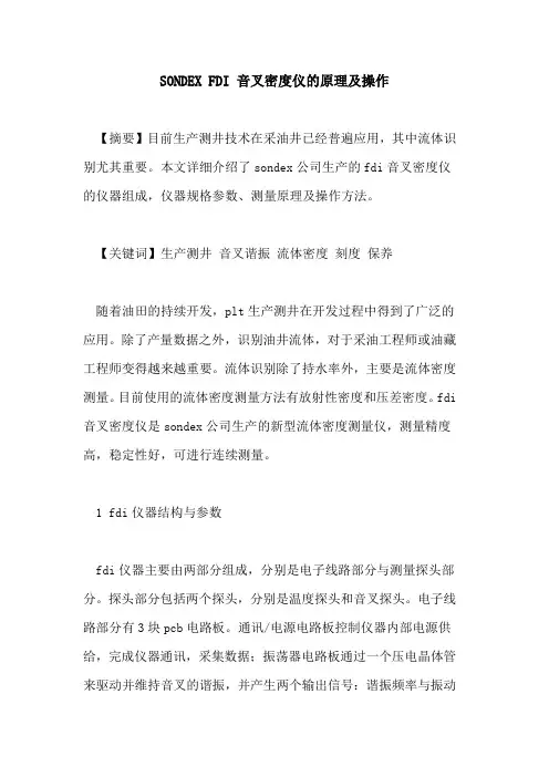
SONDEX FDI 音叉密度仪的原理及操作【摘要】目前生产测井技术在采油井已经普遍应用,其中流体识别尤其重要。
本文详细介绍了sondex公司生产的fdi音叉密度仪的仪器组成,仪器规格参数、测量原理及操作方法。
【关键词】生产测井音叉谐振流体密度刻度保养随着油田的持续开发,plt生产测井在开发过程中得到了广泛的应用。
除了产量数据之外,识别油井流体,对于采油工程师或油藏工程师变得越来越重要。
流体识别除了持水率外,主要是流体密度测量。
目前使用的流体密度测量方法有放射性密度和压差密度。
fdi 音叉密度仪是sondex公司生产的新型流体密度测量仪,测量精度高,稳定性好,可进行连续测量。
1 fdi仪器结构与参数fdi仪器主要由两部分组成,分别是电子线路部分与测量探头部分。
探头部分包括两个探头,分别是温度探头和音叉探头。
电子线路部分有3块pcb电路板。
通讯/电源电路板控制仪器内部电源供给,完成仪器通讯,采集数据;振荡器电路板通过一个压电晶体管来驱动并维持音叉的谐振,并产生两个输出信号:谐振频率与振动幅度;模拟电路板接受温度探头数据和振动幅度数据,并进行a/d 转换。
具体各部分工作状况见图1。
图1?fdi仪器工作框图fdi仪器主要参数如下:外径:1-11/16”(42.86mm)长度:20.55”(521.97mm)质量:7.81lb(3.54kg)耐温:150℃耐压:15000psi测量范围:0-1.25g/cc测量精度:±0.03g/cc分辨率:0.01g/cc响应时间:<1 seconds2 音叉密度仪测量原理音叉密度传感器是由音叉体、固支体、压电晶体管和温度传感器组成的。
音叉是呈“y”型的不锈钢发生器,其两臂对称,振动相反,中心杆处于振动的节点位置,静受力为零,不振动,因此固定在固支体上。
温度传感器贴装于固支体上,实时检测被测液体温度,用于补偿调谐叉体的弹性模量变化。
压电晶体管包括压电激励器和压电拾振器,均贴装在固支体上。
国内统一刊号CN31-1424/TB2020/5 总第282期音叉谐振式黏密度计计量性能及校准方法文慧卿 金愿 陈超云 朱绚华 / 上海市计量测试技术研究院摘 要 介绍了一种可对各类混合相液体进行黏度密度同时在线测量的方法,基于音叉谐振式原理的新型黏密度测量仪表,并通过实验分析其各项计量性能,探讨该仪器的校准方法,可以为黏密度测量行业计量校准工作提供参考。
关键词 音叉谐振式;黏度计;密度计;校准0 引言黏密度测量是石油化工、生物医药、食品能源以及国防等领域控制生产流程、保证生产安全、评定产品质量及科学研究的重要手段。
传统黏度测量方法主要包括毛细管法、旋转法、落球法、振动法[1],密度测量方法主要包括阿基米德法、等体积法、等质量法、压差式、超声波式[2],以及在此基础上为满足特定要求而进行的诸多方法优化。
传统的黏密度测量方法只能测量纯净液体,不能同时测量液体黏度和密度,最主要是不能在线测量,并且具有很大的局限性,对于泡沫非牛顿液体或含气泡等混合相液体无法进行测量。
现在市场上有一种基于音叉谐振原理的黏密度计,其利用音叉谐振原理测量液体谐振频率,从而获得液体的黏度与密度。
因其性能稳定且适用于小孔径的场合,能够适用于容量极少、黏度很低甚至含泡沫的非牛顿液体或含有固体或气泡等混合相液体的在线黏度与密度测量,而被广泛研究和应用[3-4]。
鉴于尚无针对这种黏密度计的校准方法,本文通过实验及误差分析,评估了这种音叉谐振式黏密度计的实际计量性能状况,在此基础上探讨其校准方法。
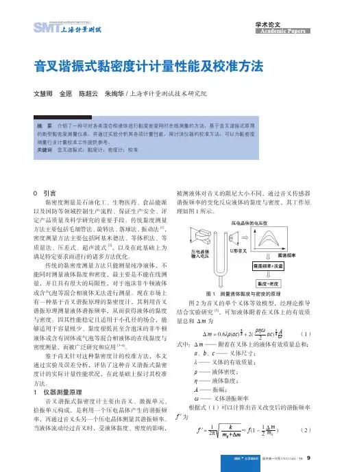
1 仪器测量原理音叉谐振式黏密度计主要由音叉、激振单元、拾振单元构成,是利用一个压电晶体产生的谐振频率,再通过音叉头另一个压电晶体测量其谐振频率。
当液体流动经过音叉时,受液体黏度、密度的影响,被测液体对音叉的阻尼大小不同,通过音叉传感器谐振频率的变化反应液体的黏度与密度,其工作原理如图1所示。
图1 测量液体黏度与密度的原理图2为音叉的单个叉体等效模型,经理论推导结合实验研究[5],可知液体附着在叉体上的有效质量总和Δm 为Δm = 0.6λρ(ac ρηω2ac (1)式中:Δm —— 附着在叉体上的液体有效质量总和;a 、b 、c —— 叉体尺寸; λ —— 叉体的有效质量; ρ —— 液体密度; η —— 液体黏度; A—— 振幅; ω —— 叉体谐振频率根据式(1)可以计算出音叉改变后的谐振频率f '为f 'f (1 - 21Δmm g ) (2)10国内统一刊号CN31-1424/TB 2020/5 总第282期式中:f ' —— 改变后的谐振频率;f —— 改变前的谐振频率; mg —— 悬臂梁的有效质量; k—— 与叉体尺寸相关的常量图2 单个叉体的等效模型引起音叉传感器谐振频率变化的主要原因是不同的液体附加在叉体上的有效质量不同,液体附加在叉体上的有效质量不仅与音叉的外形、尺寸有关,而且与液体的黏度和密度有关。
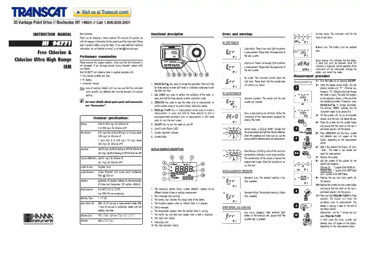
1•Turn the meter on by pressing ON/OFF .2•When the beeper sounds briefly, the LCDdisplays dashes and “P1” (Chlorine Low Range) or “P2” (Chlorine Ultra High Range)the meter is ready. The code that appears on the secondary display is the one of the RANGE/GLP/ indicates that the instrument needs to be zeroed first.3•Fill the cuvette with 10 mL of unreactedsample, up to the mark, and replace the cap.4•Place the cuvette into the cuvette holderand ensure that the notch on the cap is positioned securely into the groove.5•Press ZERO/CFM and the lamp, cuvetteand detector icons will appear on the display, depending on the measurement phase.6•After a few seconds the display will show“-0.0-”. The meter is now zeroed and ready for measurement.7•Remove the cuvette.8•Add the content of the packets for thespecific test reagents:Chlorine LR: 1 packet of HI 93701-0Chlorine UHR:1 packet of HI 95771A-0and 1 packet of HI 95771B-0.9•Replace the cap and shake gently for20 seconds.10•Replace the cuvette into the cuvette holderand ensure that the notch on the cap is positioned securely into the groove.11•Press and hold READ/ for threeseconds .countdown prior to measurement. The beeper is playing a beep at the end of countdown period.press READ//TIMER .In both cases the lamp, cuvette and detector icons will appear on the display,depending on the measurement phase.1.key: press to change the parameter. Press and hold GLP mode . In calibration mode press to edit the date and time.2.CAL CHECK key: press to perform the validation of the meter, or press and hold for three seconds to enter calibration mode .3.ZERO/CFM key: press to zero the meter prior to measurement, to confirm edited values or to confirm factory calibration restore.4.READ/ key: In measurement mode , press to make a pre-programmed countdown prior to measurement. In GLP mode press to view the next screen.5.ON/OFF key: to turn the meter on and off.6.Liquid Crystal Display (LCD)7.Cuvette alignment indicator8.Cuvette holderDISPLAY ELEMENTS DESCRIPTIONINSTRUCTION MANUALHI 96771Free Chlorine &Chlorine Ultra High RangeISMPreliminary examinationPlease examine this product carefully. Make sure that the instrument is not damaged. If any damage occured during shipment, please notify your Dealer.Each HI 96771 Ion Selective Meter is supplied complete with:•Two Sample Cuvettes and Caps •9V Battery•Instruction ManualNote:save all packing material until you are sure that the instrumentworks correctly. Any defective item must be returned in its original packing.For more details about spare parts and accessories see “Accessories”.Dear Customer,Thank you for choosing a Hanna product. This manual will provide you with the necessary information for the correct use of the instrument. Please read it carefully before using the meter. If you need additional technical information,*******************************************.Functional description Light High: There is too much light to perform a measurement. Please check the preparation of the zero cuvette.Light Low: There is not enough light to perform a measurement. Please check the preparation of the zero cuvette.No Light: The instrument cannot adjust the light level. Please check that the sample does not contain any debris.Inverted cuvettes: The sample and the zero cuvette are inverted.Zero: A zero reading was not taken. Follow the instructions of the measurement procedure for zeroing the meter.Under range: A blinking “0.00” indicates that the sample absorbs less light than the zero reference.Check the procedure and make sure you use the same cuvette for reference (zero) and measurement.1.The measuring scheme (lamp, cuvette, detector), appears during different phases of zero or reading measurement2.Error messages and warnings3.The battery icon indicates the charge state of the battery4.The hourglass appears when an internal check is in progress5.Status messages6.The chronometer appears when the reaction timer is running7.The month, day and date icons appear when a date is displayed8.Four digit main display9.Measuring units10.Four digit secondary displayON SAMPLE READINGBattery low: The battery must be replaced soon.Dead battery: This indicates that the battery is dead and must be replaced. Once this indication is displayed, normal operation of the instrument will be interrupted. Change the battery and restart the meter.Cooling lamp: The instrument waits for the lamp to cool down.DURING CALIBRATION PROCEDUREOTHER ERRORS AND WARNINGSCap error: Appears when external lightenters in the analysis cell. Assure that the cuvette cap is present.Over Range: A flashing value of the maximum concentration indicates an over range condition.The concentration of the sample is beyond the programmed range: dilute the sample and re-run the test.Standard Low: The standard reading is less than expected.Standard High: The standard reading is higher than expected.Errors and warningsON ZERO READINGMeasurement procedureTechnical specifications:Range 0.00 to 5.00 mg/L for Chlorine LR 0 to 500 mg/L for Chlorine UHRResolution0.01 mg/L from 0.00-3.50 mg/L; 0.10 mg/L above 3.50 mg/L for Chlorine LR1 mg/L from 0 to 200 mg/L; 10 mg/L above 200 mg/L for Chlorine UHRAccuracy ±0.03 mg/L ±3% of reading at 25°C for Chlorine LR ±3 mg/L ±3% of reading at 25°C for Chlorine UHRTypical EMC Dev.±0.01 mg/L for Chlorine LR±1 mg/L for Chlorine UHR Light Source Tungsten lampLight Detector Silicon Photocell with narrow band interference filter @ 525 nmMethod Adaptation of Standard Methods for the Examination of Water and Wastewater, 20th edition, 4500-Cl.Environment 0 to 50°C (32 to 122°F);max 95% RH non-condensing Battery Type 1 x 9 voltAuto-Shut offAfter 10' of non-use in measurement mode; after 1 hour of non-use in calibration mode; with last reading reminder.Dimensions 192 x 104 x 69 mm (7.6 x 4.1 x 2.7”)Weight360 g (12.7 oz.).FACTORY CALIBRATION RESTORE It is possible to delete the calibration and restore factory calibration.1•Press and hold for three secondsRANGE/GLP/GLP mode .2•Press READ/ to enter in thefactory calibration restore screen. The instrument asks for confirmation of user calibration delete.3•Press ZERO/CFM to restore the factorycalibration or press RANGE/GLP/ again 4•The instrument briefly indicates “donE”upon restoration of factory calibration prior to returning to measurement mode .or dirt and that they are inserted correctly.12•Then the date of last calibration (e.g.:“01.08.2009”) appears on the display, or “01.01.2009” if the factory calibration was selected before. In both cases the year number is blinking, ready for date input.13•Press RANGE/GLP/ to edit the desiredyear (2009-2099). If the key is kept pressed,the year number is automatically increased.14•ZERO/CFM or READ//TIMER to confirm.Now the display will show the month blinking.15•Press RANGE/GLP/ to edit the desiredmonth (01-12). If the key is kept pressed,the month number is automatically increased.16•When the correct month has been set, pressZERO/CFM or READ//TIMER to confirm.Now the display will show the day blinking.17•Press RANGE/GLP/the day number is automatically increased.Note:It is possible to change the editing fromday to year and to month by pressing READ/18•Press ZERO/CFM to save the calibrationdate.19•The instrument displays “Stor ” for onesecond and the calibration is saved.20•The instrument will return automaticallyto the measurement mode by displaying dashes on the LCD.9•At the end of the measurement the displaywill show the validation standard value.The reading should be within specifications as reported on the CAL CHECK™Standard Certificate. If the value is found out of specifications, please check that the cuvettes are free of fingerprints, oil or dirt and repeat validation. If results are still found out of specifications then recalibrate the instrument.CALIBRATIONNote:It is possible to interrupt the calibrationprocedure at any time by pressing CAL CHECK or ON/OFF keys.When calibrating, only the selected range is affected.1•Turn the meter on by pressing ON/OFF .2•When the beeper sounds briefly and theLCD displays dashes, the meter is ready.3•To change the range, simply pressRANGE/GLP/4•Press and hold CAL CHECK for threeseconds to enter calibration mode. The display will show “CAL ” during calibration procedure. The blinking “ZERO ” asks for instrument zeroing.5•Place the CAL CHECK™ StandardHI96771-11 Cuvette A into the cuvette holder and ensure that the notch on the cap is positioned securely into the groove.6•Press ZERO/CFM and the lamp, cuvetteand detector icons will appear on the display,depending on the measurement phase.7•After a few seconds the display will show“-0.0-”. The meter is now zeroed and ready for calibration. The blinking “READ ”asks for reading calibration standard.8•Remove the cuvette.9•Place the specific CAL CHECK TM StandardHI96771-11 Cuvette B into the cuvette holder, for and ensure that the notch on the cap is positioned securely into the groove.10•Press READ/ and the lamp,the display, depending on the measurement phase.11•The instrument will show for three secondsthe CAL CHECK™ standard value.Note:If the display shows “STD HIGH ”, thestandard value was too high. If the display shows “STD LOW ”, the standard value was too low. Verify that both CAL CHECK™ Standard HI96771-11Cuvettes, A and B are free from fingerprintsLAST CALIBRATION DATE1•Press RANGE/GLP/GLP mode .on the main display and the year on the secondary display.2•If no calibration was performed, the factorycalibration message, “F.CAL” will appear on the main display and the instrument returns to measurement mode after three seconds.In the GLP mode , the last calibration date can be verified and the factory calibration can be restored.To save battery, the instrument shuts down after 10 minutes of non-use in measurement mode and after 1 hour of non-use in calibration mode.If a valid measurement was displayed before auto shut off, the value is displayed when the instrument is switched on. The blinking “ZERO ”means that a new zero has to be performed.One fresh battery lasts for around 750 measurements, depending on the light level.The remaining battery capacity is evaluated at the instrument startup and after each measurement.The instrument displays a battery indicator with three levels as follows:• 3 lines for 100 % capacity • 2 lines for 66 % capacity • 1 line for 33 % capacity•Battery icon blinking if the capacity is under 10 %.If the battery is empty and accurate measurements can’t be taken any more, the instrument shows “dEAd bAtt ” and turns off.To restart the instrument, the battery must be replaced with a fresh one.To replace the instrument’s battery, follow the steps:•Turn the instrument off by pressing ON/OFF .•Turn the instrument upside down and remove the battery cover by turning it counterclockwise.•Extract the battery from its location and replace it with a fresh one.•Insert back the battery cover and turn it clockwise to close.R EAGENT SETSHI 93701-01Reagents for 100 Free Chlorine tests HI 93701-03Reagents for 300 Free Chlorine testsHI 95771-01Reagents for 100 Chlorine Ultra High Range tests HI 95771-03Reagents for 300 Chlorine Ultra High Range tests OTHER ACCESSORIESHI 96771-11CAL CHECK ™ Standard Cuvettes (1 set)HI 7213109V battery (10 pcs)HI 731318Cloth for wiping cuvettes (4 pcs)HI 731331Glass cuvettes (4 pcs)HI 731335Caps for cuvettes (4 pcs)HI 93703-50Cuvette cleaning solution (230 mL).Battery managementWarrantyHI 96771 is warranted for two years against defects in workmanship and materials when used for its intended purpose and maintained according to the instructions.This warranty is limited to repair or replacement free of charge.Damages due to accident, misuse, tampering or lack of prescribed maintenance are not covered.If service is required, contact your dealer. If under warranty, report the model number, date of purchase, serial number and the nature of the failure. If the repair is not covered by the warranty, you will be notified of the charges incurred.If the instrument is to be returned to Hanna Instruments, first obtain a Returned Goods Authorization Number from the Customer Service Department and then send it with shipment costs prepaid. When shipping any instrument, make sure it is properly packaged for complete protection.To validate your warranty, fill out and return the enclosed warranty card within 14 days from the date of purchase.Recommendations for UsersBefore using these products, make sure that they are entirely suitable for your specific application and for the environment in which they are used.Operation of these instruments may cause unacceptable interferences to other electronic equipments, this requiring the operator to take all necessary steps to correct interferences.Any variation introduced by the user to the supplied equipment may degrade the instrument’s EMC performance.To avoid damages or burns, do not put the instrument in microwave oven. For yours and the instrument safety do not use or store the instrument in hazardous environments.Hanna Instruments reserves the right to modify the design, construction and appearance of its productswithout advance notice.For additional information, contact yourdealer or the nearest Hanna Customer Service Center.To find the Hanna Office in your area,visit our web siteIST96771 11/10Factory Calibration AccessoriesCalibrationGLPLast Calibration12•The instrument directly displays concentrationin mg/L of free chlorine and the rangenumber on the LCD.INTERFERENCES FOR CHLORINE LR•Positive error: Bromine, Oxidized Manganese and Chromium, Chlorine dioxide, Ozone and Iodine.•Alkalinity above 250 mg/L CaCO 3or acidity above 150 mg/L CaCO 3 will not reliablydevelop the full amount of color or it may rapidly fade. To resolve this, neutralize the sample with diluted HCl or NaOH.•In case of water with hardness greater than500 mg/L CaCO 3, shake the sample forapproximately 2 minutes after adding the powder reagent.INTERFERENCES FOR CHLORINE UHR•Positive error: Bromine, Oxidized Manganeseand Chromium, Chlorine dioxide, Ozone andIodine.Warning: do not validate or calibrate the instrument with standard solutions other than the Hanna CAL CHECK™ Standards, otherwise erroneous results will be obtained.For accurate validation and calibration results, please perform tests at room temperature (18 to 25°C; 64.5 to 77.0°F).Validation and Calibration proceduresVALIDATIONNote:The validation is performed only for theselected parameter. For full validation of the instrument, the following procedure must be performed for each parameter.1•Turn the meter on by pressing ON/OFF .2•When the beeper sounds briefly and theLCD displays dashes, the meter is ready.3•Place the CAL CHECK™ StandardHI96771-11 Cuvette A into the cuvette holder and ensure that the notch on the cap is positioned securely into the groove.4•Press ZERO/CFM and the lamp, cuvetteand detector icons will appear on the display,depending on the measurement phase.5•After a few seconds the display will show“-0.0-”. The meter is now zeroed and ready for validation.6•Remove the cuvette.7•Place the specific CAL CHECK TM StandardHI96771-11 Cuvette B into the cuvette holder, for and ensure that the notch on the cap is positioned securely into the groove.8•Press CAL CHECK key and the lamp,cuvette and detector icons together with “CAL CHECK ” will appear on the display,depending on the measurement phase.Use the Hanna CAL CHECK™ cuvettes (see “Accessories”) to validate or calibrate instruments.。
品质保证承蒙选择本公司的密度计,深表谢意。
本机一年内免费保修、终身维护。
在保修期内若机器出现质量缺陷,测试异常情况,本公司负责免费修理或更换,由于下列原因所产生的故障除外:1)错误操作2)非本公司维修人员进行修理或改装3)本机以外的原因造成的故障4)在高温、潮湿、有腐蚀性气体、振动等恶劣条件下使用5)遇火灾、地震等不可抗力的自然灾害6)自行拆装,再进行移动或运输7)消耗品、易耗品零部件及传感器除外售后服务:1、故障时,请先阅读本说明书的《故障排除》,排除故障。
2、无法排除时,请及时与本公司售后服务部门或经销商联系。
MH-300A全自动电子密度计使用说明书请仔细阅读本说明书,以便正确使用。
请妥善保管本说明书,以备不时之需。
目录概论---------------------------------------------------------1(一)、原理------------------------------------------------------1(二)、用途------------------------------------------------------1仪器说明---------------------------------------------------------1(一)、零组件部份------------------------------------------------1(二)控制面板---------------------------------------------------2(三)、如何安装---------------------------------------------------2温机------------------------------------------------------3(四)、校正------------------------------------------------------3(五)、温度、溶液补偿设定-----------------------------------------4(六)操作步骤---------------------------------------------------4A、固体---------------------------------------------------------5B、如何量测浮体于水中-------------------------------------------5C、如何量测颗粒-------------------------------------------------6(七)操作注意事项------------------------------------------------6(八)保养-----------------------------------------------------7(九)故障排除---------------------------------------------------7十一:附录:常规液体介质的密度(单位:103千克/米3,未注明者为常温下)名称密度名称密度汽油0.70氨水0.93乙醚0.71海水 1.03石油0.76牛奶 1.03酒精0.79醋酸 1.049煤油0.80盐酸(40%) 1.20矿物油(润滑油)0.9-0.93蜂蜜 1.40植物油0.9-0.93硝酸(91%) 1.50水银13.6硫酸(87%) 1.80水(0℃)0.999867水(20℃)0.998229水(2℃)0.999968水(40℃)0.992244水(4℃) 1.000000水(60℃)0.983237水(18℃)0.998621水(100℃)0.958375(一)、原理:直读式密度计MH-300A /MH-600A 是根据GB/T533、ISO2781、ASTMD297-93、DIN 53479、ASTMD792、D618,D891、ISO1183、GB/T1033、ASTM D792-00、JISK6530,ASTM D792-00、JISK6530采用阿基米得的水中置换法原理。
GDYC700音叉料位开关使用说明书上海翔舜自动化成套设备有限公司目录提示 (03)概述 (03)了解产品 (03)工作原理 (05)技术参数 (05)安装方式 (06)电气连接 (09)仪表面板分布 (10)仪表调试方法 (10)产品选型 (11)提示:请您在选型、安装、使用本产品之前,请您认真仔细研读本产品说明书,注意本产品被限制应用的场合,注意安装方式要符合说明书中的要求,避免出现错误的安装方法,只有这样才能保证产品的长期可靠有效的运行。
概述:GDYC700系列音叉式料位开关,由于振幅可调,便于测量不同状态和密度的物料,适用于各种料仓固体物料料位以及各种容器内液位的定点报警或控制。
固体物料:粉煤灰、水泥粉、大米、塑料颗粒、盐、糖等。
液体介质:水、酸、碱、染料、油类、牛奶、酒类、饮料等。
了解产品:工作原理:GDYC700系列音叉物位开关,由发讯叉体和放大器两部分组成,在叉体根部压紧两组压电晶体,一组做为驱动器,驱动叉股产生振动;另一组做为检测器,用以将叉股振动转换成电压信号。
当叉股受阻时,振荡器的振幅变小,继电器输出开关信号。
技术参数:环境温度:-25~60℃叉体材料:铜合金或不锈钢(根据用户订货)电源电压:AC220V50/60Hz;DC24V功率:1.5W输出信号:二组常开、常闭触点;0/10mA出线口:M20× 1.5触点容量:AC220V5A物料颗粒最大外形尺寸:≤10mm容器中最大耐压:4.0MPa(定货应说明耐压)容器中的工作温度:-20~180℃(定货应说明工作温度)音叉振荡频率:约200Hz音叉尖端振幅:约0.5mm音叉阻尼延时:约2S延时调节:0~30S介质密度:不小于0.6g/cm³外形尺寸:如图1、图2、图3介质为非粘性物料:不含有对叉体起腐蚀作用的物体防护等级:IP65防爆:固体DIP、DTl3粉尘防爆(不适用于炸药场所)液体:dⅡBT4型号确定:☆确定“普通型”与特殊型”当检测坏境为常温、常压、中等粘度的液体或直径小于5m流动性较好的固体物料时可以选择“普通型”。
谐振式密度计安全操作及保养规程前言谐振式密度计是一种常用的实验仪器,在工业生产过程中也有着广泛的应用。
本规程主要旨在告知使用者如何正确操作和保养谐振式密度计,减少安全事故的发生。
操作注意事项1. 使用前的准备在使用前,需要对密度计进行一系列的检查,以确保仪器正常运行。
具体操作如下:•检查供电电源,确保稳定;•检查所有仪器设备的电缆连接是否良好;•清除密度计工作区域以确保其和样品之间没有杂质;•样品必须是常温的,且离开其来源地至少30分钟。
2. 测量操作•在进行密度测量之前,请务必清空密度计;•将密度计放在水平的平面上;•打开电源开关并保持15分钟以便仪器达到稳定状态;•根据操作手册操作,将样品倒入密度计内;•关闭电源开关,使密度计停止工作;•对密度计进行读数,记录所得数据。
3. 使用后的清理•关闭密度计电源;•移除样品设备,并用清洁的布擦拭密度计内部和外部;•将持针、啮合件、密度计杯以及管子等零部件全部拆卸,并进行彻底清洗;•在重新组装之前,必须确保所有的零部件已经彻底干燥。
保养规程密度计的保养是保证仪器长期稳定性和可靠性的关键。
下面是密度计的保养要点:1. 清洁在每次使用后,请务必对密度计进行清洁。
尤其是对于密度计杯以及密度计杯内壁,必须轻轻擦拭以保证其表面无划痕,以免影响测量准确性。
2. 定期校准密度计的稳定性与准确性是密度测量的关键指标。
为保证测量准确,定期对密度计进行校准是非常重要的。
3. 储存当密度计不再使用时,请将其存放在干燥,阴凉处,并确保密度计内部处于干燥状态。
在密度计长时间不用时,应将其孔口用封帽密封。
注意事项•使用者必须仔细阅读说明书和操作手册,了解密度测量的各项参数、测量原理,以及如何使用仪器;•如对设备不了解,请勿擅自拆卸或维修;•密度计内部严禁有金属物品等冲击振荡物体(电子秤等),有必要的情况下可以垫住以减缓冲击;•密度计本身是一个灵敏的设备,在运输、安装和搬运过程中应当小心处理,避免发生损坏。
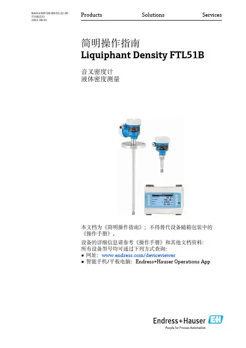
Products Solutions Services简明操作指南Liquiphant Density FTL51B音叉密度计液体密度测量本文档为《简明操作指南》;不得替代设备随箱包装中的《操作手册》。
设备的详细信息请参考《操作手册》和其他文档资料:所有设备型号均可通过下列方式查询:•网址:/deviceviewer•智能手机/平板电脑:Endress+Hauser Operations AppKA01430F/28/ZH/02.22-00715822312022-08-01配套文档资料Liquiphant Density FTL51B 1 配套文档资料2 文档信息2.1 图标2.1.1 安全图标危险状况警示图标。
疏忽会导致人员严重或致命伤害。
危险状况警示图标。
疏忽可能导致人员严重或致命伤害。
2Endress+HauserLiquiphant Density FTL51B 基本安全指南Endress+Hauser3危险状况警示图标。
疏忽可能导致人员轻微或中等伤害。
操作和其他影响提示信息图标。
不会导致人员伤害。
2.1.2电气图标 接地连接接地夹已经通过接地系统可靠接地。
保护性接地(PE)进行后续电气连接前,必须确保此接线端已经安全可靠地接地。
设备内外部均有接地端子。
2.1.3工具图标 开口扳手2.1.4特定信息图标 允许允许的操作、过程或动作。
禁止禁止的操作、过程或动作。
提示附加信息。
1.、2.、3.操作步骤2.1.5 图中的图标A、B、C ... 视图1、2、3 ... 部件号- 危险区. 安全区(非危险区)3基本安全指南3.1人员要求操作人员必须符合下列要求,例如 设备调试和维护人员:‣经培训的合格专业人员必须具有执行特定功能和任务的资质基本安全指南Liquiphant Density FTL51B4Endress+Hauser‣经工厂厂方/操作员授权‣熟悉联邦/国家法规‣开始操作前,操作人员必须事先阅读并理解《简明操作指南》和补充文档中的各项规定‣遵守操作指南和基本条件要求3.2 指定用途•设备仅可用于液体限位检测•使用不当会引发危险•确保测量设备无故障工作•确保设备的接液部件材质完全能够耐受介质腐蚀•3.2.1不当使用使用不当或用于非指定用途而导致的损坏,制造商不承担任何责任。
Kunpeng Fork level switchOperation ManualThank you for your choosing our product! Beforeoperation, please read this “Operation Manual”carefully to ensure normal operation of instrument.2 Compact type fork level switchBrief introduction to productBased on the tuning fork vibration technology, this fork levelswitch has been equipped with durable stainless steel bodyand fork so that it can be used in various kinds of fields. The3/4” or 1” economic type level switch can be fixed onto pipelineor storage tank through screw mounting, or installed onto thefood industrial facility through sanitation fastenings. In addition,the direct load switch adapts to any power supply or PNP output,also can be used as the direct interface of PLC.Product features◆ Away from the influence including water flow 、onflow 、bubble 、foam 、vibration 、solid content 、coating and liquidfeatures completely.◆ Less installation process steps without indication of positions◆ Insensitive response to polarity with short-circuit protection function◆Standard plug/socket fastenings available◆With immovable parts or gap, free-maintenance can be acquired completely◆All the information about electric components、self-check and state monitoring can be finished through LEDdisplay◆The magnetic test points make the function test easier◆Compacted design make the outline be small and exquisite◆Quicker response to viscous liquid due to its “Dripple” design◆Sanitation fasteningsMeasuring PrincipleBased on the tuning fork vibration principle, this level switch adopts piezoelectric crystal to vibrate the fork by fixed frequency of tuning fork, also the frequency variation can be monitored continuously. When used for low level alarm, the liquid in container flows down and through the tuning fork to cause the variation of natural frequency, this frequency variation can be captured by electric component so that the output mode can be switched into another one. When used for high-level alarm, the liquid inside container goes up and vibrate the tuning fork so the output mode can be changed again.3Short fork technologySelect the natural frequency (about 1300Hz) of tuning fork so that the interference which can cause faulty action of switch can be avoided effectively. The shorter fork can extend into container, thus, this product can adapt to all liquid variety, abundant researches have established stable base for high working efficiency so that this product can adapt to any kind of liquid including painting liquid、inflatable liquid and serous fluid.Special functionsLED DisplayWith LED display, it is available to carry out observation through the window of shell. When under “CLOSE” mode, the LCD display will flicker continuously (one time per 0.5s), while under “OPEN” mode, the LCD display will be on all the time.Magnetic test pointsDistributed at the side of shell, the operator can carry out function test through these test points. When one magnetic block touches the test point, the output will be changed.Electric connectionFor a quick connection, adopt standard DIN 43650 plug/socket, in addition, insensitive polarity and short-circuit protection can make the electric connection easily and safely.4Fork design“Dripple” design (drop from the end of fork) can make the test speed quicker, specially for high viscosity liquid, the scnsitivity becomes higher.5Application exampleOverflow preventionWhen in the course of loading, the overflow material will cause harm to human body andenvironment as well as production loss and cleaning cost, so this instrument is consideredas a crucial limit switch which can offer overflow signal at any time.Pump protectionThe length of short fork inserting wet side is shortest and can be fixed onto pipeline andcontainer at any angle so that the installation cost can be reduced effectively. Because theextending length of fork is 2 inch only (50mm), it is available to install this instrument ontominorcaliber pipe. If combined with direct-load switch, this instrument can become an idealchoice for the reliable control of pump, also away from dry running of pump.Top and lowest level alarmBecause this instrument can works continuously under 302°F(150℃)temperature and1045 psig (100barg) pressure due to its hard and durable shell, so this product is an ideal oneused to detect the top and lowest of different storage tank. Generally, a separated level alarmswitch is equipped so that an extra standby switch can be provided when failure emerges.6Leakage detectFor flange、gasket、seal ring, there may be leakage when exposed to severe environment likecorrosive liquid. Most of the storage tank and container are installed onto base plate or insideprotection body in case the liquid leakage emerges. This instrument can be used to find out theleakage point quickly and accurately so that the detecting cost can be reduced obviously.Pump controlFor many processes, equipped batch process and elevated storage tank, so a control to pumpbecomes very important to make the liquid level at specified range. Generally, these storagetanks are made of thinner material so that it can not be used to bear heavier instruments.Sanitation applicationDue to its higher surface smooth finish(Ra) which can be more than 0.8 μm, this instrument canmeet the requirements of food and medicine manufacturing. In addition, this instrument is made ofstainless steel so that it has a good durability, thus, it can be used under 302°F(150℃)hightemperature steam cleaning (CIP).7Application and installationInstallation precautions◆Before installation, check if the liquid temp and pressure are at the specified range (see technical specification) ◆Check if the viscosity of liquid is at the recommended range: 0.2 to 10000 cP◆The products with high viscosity include chocolate syrup、tomato catsup、peanut paste and asphalt.Even though these things have a high viscosity, the instrument still can carry out detection, but the discharging time is very long.◆Check if the density of liquid is more than 37.5 lbs./feet3 (600kg/m3).◆the things with low density include acet.、pentane and hexane◆Check if the fork is at the risk of material accumulation◆away from the conditions like accumulation of dry and coated things◆ensure that the fork is away from lapping (joint) caused by high density things◆the things which can cause the lapping of forks include:thickened pulp and asphalt(um)◆Check if there is solid material contained inside the liquid◆If an agglomeration phenomenon emerges, this will cause serious problem.◆ T he max. solid particle shall be within 0.2”(5mm)◆When used in the liquid with over 0.2”(5mm) solid particle, a special consideration shall be took into account,also you may contact the manufacture for solution.◆Foam◆ Generally, this instrument is insensitive to foam, so there is nothing to the test result by foam.◆But, for some individual case, the thickened foam is used as a carrier, for example, in the process of8manufacturing of ice cream, the foam influence shall be took into account.Recommended installation◆ Before installation, turn the switch to “ON” position◆ For high liquid level, turn on “Dry” button◆ For low liquid level, turn on “Wet” button◆It is strongly suggested that the magnetic test points should beused to detect the system all the time when at debugging course.◆Around the instrument, a sufficient space should be left so thatthe installation and electric connection can be implemented (seedimensional drawing for details)◆ Do not install the instrument onto the position where is close to theinlet of liquid.◆ The tuning fork should be kept away from the large number ofsplashed liquid.◆ Ensure that the tuning fork is not in touch with tank wall or any internal partsor any interfering thing.◆Ensure that the tuning fork can be kept a certain distance with accumulative FIG1:Correct installation drawingmatter on the wall of storage tank.9Technical specificationPhysical characters◆ Product: compacted level switch◆ Measuring principle:based on the vibration of tuning fork◆Application: adapt to most liquids including painting liquid、inflatable liquid and serous fluidMechanical features◆ Material of main parts: 316L stainless steel (1.4404)For the tri-clamp joint, the surface smooth finish can be more than 0.8μm, the material for 1” BSPP(G1) gasket is non-asbestos BS7531 X carbon fiber, and added with rubber adhesive.◆ Shell material: Body of shell: 304 stainless steel with polyester labelLED display window: inflaming retarding vanamid (Pa12) UL94 V2Plug: Daiamid GRPSeal ring: nitrile rubber 122“(50mm)◆ Installation material: 3/4” BSPT (R) or NPT1” BSPT (R) or NPT (G) screw or 2”(21mm) sanitation tri-clamp joint10◆Dimensional drawing: See “dimensional drawing” for details◆Explosive-proof grade: IP66/67, meet the standard EN60529Performance◆ Hysteresis range(water): ±0.039”(±1mm), rated value◆ Switch point (water): the distance to fork end (vertical) andthe edge of fork (horizontal) is 0.5”(13mm), this value will changewith the variation of liquid density.Function features:◆ Max. operating pressure: depend on the fastening of storage tank◆ Screw fastening: see FIG2 for details.◆ Sanitation fastening: 435psig (30barg)◆ Temperature: see FIG3 for details.11◆ Liquid density: Min. 37.5 lbs./foot3(600kg/m3)◆ Liquid viscosity range: 0.2 to 10000cP (centipois)◆ Solid content and painting type: it is recommended that the max. particle of the solid in liquid is 0.2”(5mm)For painting type product, the lapping (joint) of fork should be avoided.◆ Switching delay: 0.3 to 30s◆ CIP (clean in position) clean: available to be exposed to 302°F(150℃)high temperature steam for clean.Functional Characteristics◆ Switch type: toggle switch available, also the user can choose another one.◆ Cable connection: a four-way joint can be used for the connection of cables, this meet the standard DIN43650.the max. size of wire :15AWG, in addition, a four-direction bearing unit has been equipped as well (90/180/270/360°)◆ Wire size: max. 0.06 inch2 (1.5mm2)◆ Cable sealing device: a PG9 device can meet the requirements of 0.24-0.31”(6-8mm)Other components◆ Switch shell: made of durable stainless steel and equipped with a LED display window made of daiamid, besides,a four-way joint has been equipped as well and meet standard DIN43650, also a four-direction bearing unit aswell sealing device of cable are equipped as well.◆ Electric components: a standard double-core cable( which can be connected with 15-28V AC power) can be usedto connect this instrument with load equipment to acquire direct load switch which can be used as single-pole single-throw (SPST) switch. In addition, it can be used as a direct interface for PLC on the base of 24V DC solid12PNP output, at the same time, a relay with large capacity can meet the strong current output which can be up to 5A at most.◆ Fastenings of storage tank and tuning fork: for the wet parts material, they are made of 316 stainless steel, and forfork, it is available to use shorter length or half extending structure. You may see the dimensional drawing for details.◆ Screw connection: Screw 3/4”NPT or BSBT (R) 、1”BSBT(R) or BSPP (G)Material: 316L stainless steel◆ Sanitation fastenings: Fittings 2”(51mm) Tri-clamp joint 、1” BSPP (G)、o-ringMaterial: 316L stainless steelAccessories:when used in a position where has a high requirement for sanitation, aauxiliary piece can be used to match 1”BSPP or 2”(51mm) tri-clamp joint.In addition, at the wet side of tri-clamp joint, the manual smooth finish can bemore than 0.8 μm, so this can meet the requirement of severe sanitationstandard.◆For the dimensional drawing of product, please see the below page for details13Dimensional Drawing14Electric connection diagram15Normal Fork Level SwitchBrief introduction to productBased the vibration of piezoelectric crystal, this instrument can be activated toacquire measuring result. When encounter damping action, the vibration amplitudedecreases sharply, also the frequency and phase position changes obviously,all of these changes will be detected by the electric components inside, thentransferred into switch signal for output after process. Thus, this instrument can beused to carry out high-low level test and control as well as alarm function for storagetank, suitable for various kinds of liquids、powders and particle solid. In addition, due to its high availability and stable performance, this instrument can be almost free to maintenance and adapt to various environments, adopt LED to indicate the working state, generally, there are three input modes including DC24V、AC 110V and AC 220V and many output modes like DC current output、relay contact output and DC voltage output, for all of these modes, a high-low level alarm mode is equipped and available to set the sensitivity of instrument.Product features◆Away from the influence including water flow、onflow、bubble、foam、vibration、solid content、coating and liquidfeatures completely.16◆Less installation process steps without indication of positions◆Insensitive response to polarity with short-circuit protection function◆Standard plug/socket fastenings available◆With immovable parts or gap, free-maintenance can be acquired completely◆LED indicator lamp which can be regulated as required◆Quicker response to viscous liquid due to its “Dripple” design◆Sanitation fasteningsMeasuring principleBased on the fork vibration theory, this instrument is designed as a level switch which makes use of the piezoelectric crystal to vibrate the fork by the natural frequency of fork, in addition, the frequency variation can be monitored continuously. When used for lower alarm application, the liquid in container flows down and through the tuning fork to cause the variation of natural frequency, this frequency variation can be captured by electric component so that the output mode can be switched into another one. When used for high-level alarm, the liquid inside container goes up and vibrate the tuning fork so the output mode can be changed again.Technical parameters※Medium temp: -20~80℃※Ambient temp:-20~60℃※Ambient humidity: ≤95%17※Medium type: liquid、powder or particle solid※Medium density: Solid ≥0.1g/cm3Liquid≥0.7g/cm3※Solid particle size:≤10mm※Max. liquid viscosity:<1000mm2/s※Medium angle of repose:≥200※Pressure range: ≤ 1MPa※Shell material: Die-casting aluminum※Fork material:1Cr18Ni9Ti※Degrees of protection provided by enclosures:IP65※Connection mode: G1 1/2 screwFlange(option)※Electric parameters1. Power supply: DC24V, AC220V 50Hz2. Output signal: relay output 5A 220V AC3A 24V DC※Power consumption: ≤2W18※Fork vibration frequency:300±50Hz※Ambient vibration grade: V.L.4,less than 1g accelerated velocity※Switching signal response time:1-60sElectric connectionThe wire connection for instrument is shown as follows, the connection terminal with POWER is used to connect with power supply (AC 220V or DC 24V), No.3,4,5 are the output terminals of relay.Red light--------Indicate the output mode of relayGreen light--------Indicate the fork modeDebugging-------when the LIMIT ELECTED is under L sector, the red light is on, at the same time, if the fork is19vibrating ,the green light will be on as well. In addition, the terminal 3and 4 should be under normal close mode, while terminal 3 and 5 should be under normal open mode. When use your hand touch the fork, the fork stops vibrating and the green light is off, the relay contact turn around, conversely, the terminal 3 and 4 will be under normal open mode , and the terminal 3,5 will be under normal close mode; lastly, regulate the action delay time at the range 1~60s.If the LIMIT SELECTED is under H sector, the red light will be off, at the same time, the fork vibrates and the green light is on; the terminal 3 and 4 is under normal open mode, while the terminal 3 and 5 is under normal close mode, when touch the fork, the fork stops vibrating and the green light is off; at the same time, the contact of relay turn around, conversely, the terminal 3 and 4 become normal open, while the terminal 3 and 5 become normal open, lastly, regulate the delay time at the range of 1~60s.Generally, just select the LIMIT SELECTED at L sector to select the output terminals of relay so that the upper and low limit alarm can be acquired.Sensitivity regulation: this regulation should be done according to the density of medium, the lower density, the higher sensitivity. After regulation, press RST for confirm, generally, H sector is reasonable.After the state indicator light has been selected, carry out connection as description, and turn on the power supply after checked to be correct. Next, use your hand to touch the fork to check if the indicator light change the state, when pull out the hand, the indicator light will resume immediately. Repeat this operation several times to confirm it can work normally before put into use.Installation method1. Generally, this instrument should be installed vertically with downward fork end, also horizontal or inclinedinstallation is acceptable (if the adhesivity of material is high, it is suggested that the fork should be installed vertically downward)2. The installation mode with the upward fork is forbidden203. For the material with lumpy or hard particles, it is suggested that the fork should be installed vertically orslantingly.4. Before installation, it is suggested that a small quantity should be sampled to test the sensitivity of instrument. Forexample: immerse the instrument into a container with medium to test its reliability.5. When in the course of actual installation, there are various installation modes including top installation, side wallinstallation and pipe installation as shown in the following FIG:21Points for attention1. Away from the restricting to the vibration of fork due to material agglomeration.2. When installed at the position with scar, a enough space shall be left between the fork and tank wall3. For the instrument used for liquid level monitoring, the test point should be selected as the actual height.4. For low viscosity liquid, the liquid can flow through the fork smooth, so it is available to carry out installation at anyposition as above FIG.5. For high viscosity, it is difficult that the medium can flow through the fork, so it is suggested that the fork endshould go downward and vertically for installation6. For the instrument used for material level monitoring, the installation position of vertical cylinder or similar notonly depends on the height of material level, but also take into account the angle of repose as well as the feeding position. When under horizontal installation, the fork end should be placed at inner wall by 1/3 radius of container, and the two forks pieces should be put into the same plane. When under vertical installation mode, the distance between the installation center and inner wall of container should be 1/3 radius of container. In addition, the installation position should be away from the direct impact and splash of material medium as much as possible in case cause fault actions or wearing; if failed to avoid the impact or splash of material, a protection eaves should be installed at the installation position of instrument, the length of eaves should be longer than the actual one of instrument.22WARNING!When install or operate, do not hold the fork piece of instrument or knock in case cause deformation of fork piece, even cause damage to internal electric components.Dimensional DrawingScrew InstallationPopular type Extension type23Flange InstallationPopular type Extension type24。
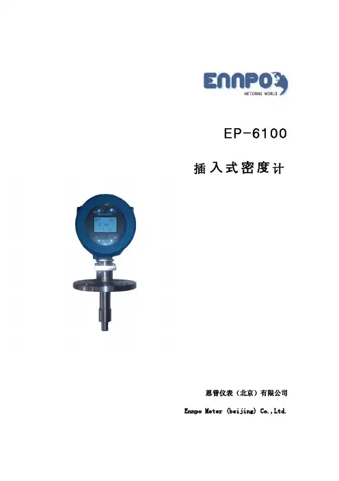
上海,201206,中国Micro Motion插入式密度计简要说明上海,201206,中国适用范围:7826/8插入式密度计是安装在管道上、敞开或密闭储罐中,可连续、实时在线测量流体密度的传感器,用于以密度做为最终产品首要控制参数的过程控制,或用于固体百分比或浓度百分比等其他质量控制参数的指示器。
材质选择:对于316L、Hastelloy C22、304、Titanium等材质在应用于腐蚀性介质时,可以参考Micro Motion的腐蚀指南做为选型依据;其他材质,如Hastelloy B2、Monel400,在选用前请咨询工厂。
密度计的PTFE衬层的作用是减少被测介质的粘附,不是用于防腐蚀的目的,在用于腐蚀性介质时仍基于音叉本体材质考虑。
颗粒限制:在测量含有颗粒的液体时,要注意颗粒的直径与百分比含量,具体数据见下表。
上海,201206,中国安装方式:根据安装位置及介质条件,主要有以下三种安装方式。
1、根据管道尺寸及介质的流速、粘度等选择安装方式。
(1):当主管道流速大于1.5m/s 且无结蜡现象产生时,可用于粘度不大于250cP 的场合。
(2):如被测介质是浆液参见脱硫安装要求。
(3):当管道流速大于3m/s 时,参照下表确定音叉的位置。
上海,201206,中国2、安装方式示意图(1)自由安装(以7826为例)(2)T型套管安装(以7826为例)上海,201206,中国(3)流通室安装3、安装注意事项(1)音叉位置注意,在任何安装形式下,音叉在液体中都应该处于垂直位置,以避免杂质沉降以及气体积聚对测量的影响。
上海,201206,中国(2)保温措施在密度计本体及安装位置出现热交换以及温度梯度变化都将影响密度测量的准确度,为了获得期望的测量精度,密度计以及相邻的管道要采取良好的隔热措施。
必要时,可以选择weldlot安装形式,以减少热交换。
这种安装形式仅用于4”以上管线。
(3)安装位置选择流态分布稳定的位置安装密度计,避免安装在阀门、弯头及节流元件等对流体产生扰动的位置,以获得期望的测量精度。
一种音叉密度计校准方法陈超云; 文慧卿; 王灿【期刊名称】《《上海计量测试》》【年(卷),期】2019(046)005【总页数】4页(P6-8,11)【关键词】音叉密度计; 谐振频率; 密度测量; 校准方法【作者】陈超云; 文慧卿; 王灿【作者单位】上海市计量测试技术研究院【正文语种】中文0 引言音叉密度计采用插入方式安装于管道或容量罐上,用于动态或静态测量介质的密度[1-3]。
广泛应用于石油化工、矿物加工、制糖、制碱性等行业,能适用于高黏度、固液混合物、需要蒸发浓缩、结晶析出以及混合溶液的密度测量[4-6]。
但是目前尚无音叉密度计的校准规范,无法对仪器的计量性能进行评判。
音叉密度计校准的最大问题是溯源标准的选择和标称值的测定。
目前音叉密度计溯源可以参照一等标准密度计和液体标准物质[7]。
一等标准密度计主要是针对玻璃浮计类仪器量传和溯源,对于数显式仪器,一等标准密度计需要修正毛细常数和玻璃膨胀系数,只能用于低精度的数显仪器校准[8]。
液体标准物质是理想的溯源标准,但是我国目前尚未研发出液体标准物质,只能依赖于向国外进口,价格十分昂贵,而且包装剂量为毫升级,无法满足音叉密度计的用液需求[9]。
本文提出了一种以U 形振动管密度计为溯源标准的音叉密度计校准方法,通过测定溶液密度,将标称值与被校音叉密度计示值比较,并以此为基础建立起音叉密度计的校准装置。
在0.8~1.5 g/cm3 密度范围内进行校准实验,为该类仪器的校准提供一种现实可行的方法。
1 音叉密度计原理及仿真音叉密度计采用共振原理设计而成,主要是由音叉叉齿、驱动压电晶体、检测压电晶体、温度传感器以及数显仪表组成,其几何结构示意图如图1所示。
图1 音叉密度计结构音叉叉齿根部的驱动压电晶体激励下,音叉产生一个基本振动频率,两叉齿按相反方向振动,当有液体流经音叉时,液体的密度改变了基本振动频率,位于叉齿齿根的另一个检测压电晶体,拾取振动频率,同时温度传感器测得液体温度,以此修正叉齿的弹性模量,并将最终频率信号传输给数显仪表,转换为密度值。
音叉式物位开关安装使用说明书在使用本产品前请阅读产品安装使用说明一、拆箱小心的打开包装箱并除去包装箱内的填充物,仔细核对装箱单上的每项条款,包括仪表型号、安装附件、说明书等,若发现有缺货,与装箱单不符或破损现象,请立即与我公司联系。
二、查看说明书该说明书包括仪表的技术参数、安装及调试规范,请仔细阅读说明书中的每一项内容,如对说明书中的内容有不明白的地方,可以打电话或传真的方式与我公司联系。
系列物位开关包括1个传感元件、1个电子单元及1套壳体三、概述音叉式物位开关是一种新型的物位开关。
音叉由晶体激励产生振动,当音叉被物料浸没时振动频率发生变化,这个频率变化由电子线路检测出来并输出一个开关量。
工作原理根据物料对振动中的音叉有无阻力,探知料位是否到达或超过某高度,并发出通断信号,这种原理不需要大幅度的机械运动,驱动功率小,不必校准,可快速低成本启动。
结构简单,无机械运动部件,无维修、无磨损,运行寿命长,灵敏而可靠。
传感器的音叉以固有的频率振动,当音叉触及液体或其他物料时,其固有的振动频率降低,能量消耗在物料颗粒间的摩擦上,迫使振幅急剧衰减而停振,频率的变化激活液位开关,产生通断信号。
音叉式物位开关又被称作“电气浮子”凡使用浮球液位开关和由于结构、湍流、搅动、气泡、振动等原因导致不能使用浮球液位开关的场合均可使用“音叉式物位开关”。
由于音叉物位开关无活动部件,因此无须维护和调整,是浮球液位开关的升级换代产品。
音叉式物位开关广泛应用于石化、轻工、食品、水处理等行业,对物位进行上/下限位报警及控制。
四、产品特点✧适应性强:被测液体不同的电参数、密度对测量均不产生影响。
结垢、搅动、湍流、气泡、振动、中等粘度、高温、高压等恶劣条件对检测也无影响。
✧不需调校:由于音叉限位开关的检测不受被测介质电参数及密度的影响,所以无论测量何种液体都不需现场调校。
✧免于维护:由于音叉限位开关的检测过程由电子电路完成,无活动部件,所以一经安装投运使用便不需要维护。
1.概述在工业生产中,液体密度是需要测量的重要物理特性,特别在电子厂、化工厂、炼油厂和品加工厂液体密度的测量是必不可少的。
新型DM8振动式密度计具有高可靠性和丰富的操作功能。
仪表包括检出器和变换器,检出器有振动器和RTD(电阻温度计),它输出检出密度信号(频率)和温度信号(电压)到变换器,变换器用微处理器转换从检出器送来的密度值的频率信号并显示,它也能计算参考温度下这些信号的密度并用数字显示。
变换器除了输出模拟传出信号还可输出数字传输信号并提供多种功能。
如——触式校验、自诊断等。
1.1技术标准说明1.1.1测量对象:液体密度测量原理:振动式密度测量±测量量程:密度:0.5~2.0g/cm3温度:-10~100℃检出器与变换器之间距离:2km以下电源:90~132V AC或180~264V AC,50/60HZ消耗功率:20V A特性:重复性:5*10-4g/cm3(对数字输出而言)量程的1%(对模拟输出而言)线行:量程的±0.5%(当量程0.2g/cm3或更小)量程的±1%(当量程0.2~0.5g/cm3)温度特性:±0.5%/±10℃变化。
流量特性:0-5g/min的±0.1%压力特性:±0.0005g/cm3/±1kg/cm3变化粘度误差:0-1500CP的±0.1%1.1.2检出器普通型密度计:VD6D型检出器构造:非防暴防雨构造外壳材料:铝合金铸件外壳颜色:翡翠绿(相当于孟塞尔色度的7.5BG4/1.5)外壳铸衬:烘涂环氧(树脂)重量:约12kg安装:安装在2寸管上(JIS50A)环境温度:-10-50℃振动器材质:不锈钢JIS SOS316或镍测量液体温度:-10-100℃测量液体压力:小于(20kg/C㎡G)2Mpa最大压力:((50kg/C㎡G)5Mpa蒸气拌热:有过程连接:JIS PT 1/4 内螺纹电气连接:JIS PF 3/4内螺纹防火防爆型检出器 VD6DF型检出器构造:JISd2G3防火或FM防火型构造电气连接:JISPF3/4内螺纹或3/4NSM内螺纹(注)除以上防火型构造外,其余的和(1)中普通型说明一样卫生新法型检出器:VD6S型过程连接:用JIS6A(公称直径6mm)管子特殊连接蒸气拌热:没(注):除以上两点之外,其余的和(1)中普通型说明一样1.1.3变换器 DM8C型外壳构造:防尘防雨构造铸寸颜色:前门,相当于孟塞尔色度的2.8GY6.4/0.9外壳:相当于孟塞尔色度的2.8GY3.1/0.5外壳铸衬:烘涂环氧树脂安装:安装在盘面、墙上和JIS50A管重量:约7.5kg环境温度:-10-50℃显示:数字显示,5位LED数字显示显示内容:参考温度下变换后的密度值;测量温度下的密度(g/cm3);测量液体温度(℃)校验液体密度设定值(调用显示);校验液体温度系数设定值*10-5g/cm3/℃(调用显示);输出量程的低限(%)(调用显示);输出量程的高限(g/cm3)(调用显示);参考温度(℃)(调用显示);测量液体温度系数设定值(-1*10-5g/cm3/℃)(调用显示);检出器系数A,B(调用显示);检出器校验系数C,D(调用显示);故障内容显示;模拟输出信号:4-20Ma℃和0~1V℃传送数据;参考温度下变换后的密度;量程:0.05~g/cm3数字输出信号的接口:RS-232C⑴通讯标准异步系统起动位: 1停止位: 2奇偶: 没数据传输:1200位/S传输系统:ASCⅡ,字母长度:8位接线系统:两线制输出⑵输出信号传送内容:测量数据(参考温度下变换后的密度(g/cm3);测量温度下的密度(g/cm3);测量液体温度(℃);校验状态(校验起动,误差编号,校验结束);故障报警(误差编号).信号电平输出电压:ON,9±3V,OFF,-9±3V输出阻抗:300欧姆输出格式测量数据#*.**** **** ***.*CRLF(注):数据按照参考温度下变换后的密度,测量温度下密度,测量液体温度的顺序输出.在校验或维护方式时输出保存数据(输入(出)方式时的正当值).而校验或维护方式转换后,保存的数据马上被解除.校验状态#CALIBRTION START CRLF(注):校验时无数据输出,然而,当发生参数误差时,输出就变成如下:#ERROR *CRLF(*:5.0r6)#CALIBRATION END CRLF故障报警#ERROR *ERROR *......CRLF( 注):当发生多种误差时,输出相应的各个误差编号.例:#ERROR-1 ERROR 3CRLF异常状态的触点输出:常闲单点触点(16)最大电压:220V.DC,250V.AC最大电流:2A(电阻负荷)最大触点电压:60W.检出器异常的内容:检出器和变换器异常.输出信号的保存:当处于校验(CAL)和维护(MAIT)方式时被保存,如出现故障状态,减少10%数据被保存.温度系数设定范围:0~0.002g/cm3/℃校验方法:通过设定液体密度的一触式校验.空气吹扫连接:JIS PT1/8,PT1/4内螺纹或1/4NPT内螺纹(供选择)电缆入口Ⅱ:27㎜直径,五孔,盖有四个相当于JISA15的防水塞子,一个相当于JISA20塑料防水塞子(附件).电源:90~132VAC或180~264VAC,50/60HZ1.1.4 专用电缆:DM8W型型号:六芯双屏蔽电缆绝缘:聚乙烯护套:聚氯乙烯绝缘电阻:1000Me/km导线电阻:15.3欧姆/km外径:15.8mm1.1.5 附件注射采样测量液体的注射器 1PC刷子(清洗振动器用) 1PC开启接线箱的六角螺钉扳手 1PC取检出器盖子的六角钢板手 1PC干燥剂 2PC变换器的保险丝 1PC1.2型号和后缀符号1.22防火型检出器1.2.3卫生型检出器1.2.4变换器1.2.5专用电缆1.3外部尺寸1.3.1检出器1.2.3卫生型检出器1.2.4变换器1.2.5专用电缆1.3外部尺寸1.3.1检出器普通防火型图1.4使用防火型、防爆型仪表的注意事项1.4.1 防火型仪表的概述防爆仪表的技术标准符合有关的国际组织的规定。