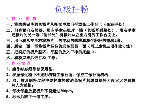
铝壳锂电池返工通用SOP
- 格式:xlsx
- 大小:5.95 MB
- 文档页数:3

关于金属锂电池和锂离子电池操作指引(第一版)根据IATA DGR 50版关于锂电池运输的最新规定将从2009年1月1日起生效。
为保证运输安全以及操作顺畅,CX/KA(PVG)根据本公司有关规定,特制定以下操作指引:一, 锂电池运输必须证明符合联合国《试验与标准手册》第III部分38.3的每一项测试规定。
CX/KA(PVG)认可的锂电池运输鉴定机构见附件A. PVG出港必须出具认可的检测机构出具的《货物运输条件鉴定书》二, 锂电池(Lithium Battery)作为非限制性货物运输1. 包装要求请根据所运输锂电池货物的实际运输专用名称, 查阅IATA DGR 50 版运输锂电池相对应的包装说明Part 1(PI965, 966, 967, 968, 969和970), 包装必须满足该锂电池货物所对应的要求.2. 单证要求1)在所附文件, 如货运单上填写以下a-d的所有内容。
运单上的空白处如果无法包含相关内容,请另附声明,此时运单上须注明“Document as per attached ”. 除此之外(a)中提到的内容在任何情况下仍需显示在运单上。
a. 注明包装件内含有锂电池(无论是锂金属电池还是锂离子电池)Lithium ion batteries or cells, NOT RESTRICTED as per PI 9xx Part1; orLithium metal batteries or cells, NOT RESTRICTED as per PI 9xx Part1; orLithium ion and metal batteries or cells, NOT RESTRICTED as per PI 9xx Part1b. 锂电池的包装件,操作时必须注意小心轻放,原因是因为包装件发生破损容易引发起火危险如“The package must be handled with care and a flammability hazard exists, if thepackage is damaged.”c. 根据对应的包装说明,注明当包装件破损情况发生时的处置说明如:“Do not Damage or mishandle this package. If package is damaged, batteriesmust be protected so as to prevent short circuit.”d.填写24小时电话联系人,联系人的电话必须保持畅通, 以便获取更多的货物有关信息。


文件编号 SL-JS-034版本/版次A0标 题423845A r -800m A h 工艺文件第1页 共1页编制:审核:批准:生效日期正极片正视图:5 mm正极片俯视图:负极片正视图: 1.5-2.0mm负极片俯视图:铝壳规格:4.2-0.03×37.8±0.05×43.8-0.1mm 及配套盖板。
正极双面密度 42.8±0.4mg/cm 2负极双面密度18.4±0.2mg/cm 2敷料量正极净重:6.21±0.12g 负极净重:2.82±0.05g正极基体:16μm ×296mm 铝箔 负极基体:10μm ×406mm 电解铜箔 正极压片厚度:123~129μm 负极压片厚度:122~128μm 正极极耳规格: 4×0.10mm 负极极耳规格: 4×0.08mm负极耳贴高温胶纸:宽6mm高温胶上部与极耳头部留位:1.5-2.0mm隔膜纸 846±2×42×0.016mm 正极耳外露长度 5mm绝缘片 32×3.2×0.20mm 负极耳外露长度 3.5~4.0mm卷 针 宽度:31.7±0.2mm 铝镍复合带规格 3.0×0.15mm注液量 2.5~2.8g钢珠:1.30mm封口厚度 ≤4.3mm分容电池分类标准分类A C ≥810mAh ;(1000~1010mAh 为a 级)A1 760mAh ≤C <800mAh ;(750~760mAh 为a1级) B1 700mAh ≤C <750mAh ;B2 600mAh ≤C <700mAh C 0mAh ≤C <600mAh ;备 注:1、压芯时间为4~8s.2、压片后正极片延伸系数为0.8±0.2%、负极延伸系数0.3±0.1% 3.正极装配极片厚度<129μm ,负极装配极片厚度<128μm. 4、焊接极耳时,正极要求3个有效点,负极要求6个有效点 5、压芯厚度3.15~3.40mm 卷绕正极13面 负极11面。


正极片贴胶纸作业指导书一、所需设备/工具/物料正极片、小刀、托盘、8mm或6mm宽的OPP胶纸、棉手套、手指套二、操作步骤1、将正极片从托盘中取出平放在不锈钢面的工作台上。
2、将8mm或6mm宽的OPP胶纸用刀片尖牵引至极片一端贴盖住正极耳(用6mm宽的OPP胶贴时贴住粉位1mm)。
3、当贴至正极片下端齐平时用刀割断8mm宽的OPP胶(用6mm宽的OPP胶贴时翻转正极片,贴住正极耳至初始位置反面时用小刀划断即可)。
4、将OPP胶长出极片位置部分折贴到极片的另一面即可,逐个贴好OPP胶纸后放入托盘。
5、进行5S工作。
三、工艺要求/注意事项1、OPP胶与正极片顶端齐平。
2、正极片贴OPP胶纸时要贴实贴到位,禁止胶纸起皱或极片贴胶纸后不能自然伸展。
3、作业时必须保持工作台面洁净。
包高温胶纸作业指导书一、所需设备/工具/物料负极耳、小刀、8mm宽的高温胶纸、棉手套、手指套二、操作步骤1、将负极耳齐头均间隔排在不锈钢面的工作台上。
2、将8mm宽的高温胶纸距齐头的一端2.0~2.5mm贴盖住负极耳。
3、用小刀在均间隔中间位置划断。
4、将负极耳逐个包好高温胶纸。
5、进行5S工作。
三、工艺要求/注意事项1、高温胶距负极耳顶端2.0~2.5mm。
2、负极耳包高温胶纸最多不超过3层。
3、如不好定位可制一条PVC档板和一条2mm宽的定位板。
4、作业时必须保持台面洁净。
负极片贴胶纸作业指导书一、所需设备/工具/物料负极片、小刀、托盘、8mm或6mm宽的OPP胶纸、棉手套、手指套二、操作步骤1、将负极片从托盘中取出平放在不锈钢面的工作台上。
2、将8mm或6mm宽的OPP胶纸用刀片尖牵引至极片一端贴盖住负极耳(贴住粉位1或0.5mm)。
3、翻转负极片,贴住负极耳至初始位置反面时用小刀划断即可。
4、将负极片按工艺要求逐个贴好OPP胶纸后放入托盘。
5、进行5S工作。
三、工艺要求/注意事项1、OPP胶出负极片顶端2-3mm。
2、负极片贴OPP胶纸时要贴实贴到位,禁止胶纸起皱或极片贴胶纸后不能自然伸展。

锂电池管理规章制度内容第一章总则第一条为规范锂电池的管理和使用,保护环境和人员安全,根据相关法律法规,制定本规章制度。
第二条本规章制度适用于公司内部所有使用锂电池设备的部门和员工。
第三条锂电池是一种危险品,必须按照规定的程序进行管理和使用,不得私自处理或丢弃。
第四条公司将针对不同的锂电池类型和用途,制定相应的管理制度和操作规程。
第五条公司将定期对锂电池进行检测和维护,确保其正常使用。
第六条公司将对锂电池的使用进行记录和监控,发现异常情况及时处理。
第七条公司将加强员工的锂电池安全教育和培训,提高员工对锂电池的认识和意识。
第二章锂电池管理第八条公司将对购买的锂电池进行登记和编号,建立使用档案。
第九条锂电池应存放在通风干燥的地方,远离火源和易燃物。
第十条锂电池在运输过程中应使用专用的包装,避免受到损坏。
第十一条锂电池使用前应进行检查,确保外包装完好无损。
第十二条锂电池使用过程中,应严格按照说明书进行操作,不得超负荷使用。
第十三条锂电池使用完毕后,应妥善保存,并定期进行充电保养。
第十四条锂电池不得拆卸或破坏外壳,否则可能导致短路或漏电。
第十五条锂电池损坏或失效时,应及时报修或更换,不得私自处理。
第十六条锂电池的使用期限为5年,超过期限的应及时报废处理。
第十七条锂电池应定期进行安全检查和维护,确保其正常运行。
第十八条锂电池在使用过程中产生的废弃物应按规定进行分类处理。
第三章锂电池安全第十九条锂电池使用过程中应注意防止过充和过放,避免引发火灾或爆炸。
第二十条锂电池运输过程中应采取防撞、防摔等措施,确保安全。
第二十一条锂电池使用过程中应及时发现并排除潜在的安全隐患。
第二十二条锂电池使用过程中应严格遵守操作规程,确保安全运行。
第二十三条锂电池使用人员应接受相关安全培训,了解处理紧急情况的方法。
第二十四条锂电池发生事故时,应立即停止使用,并通知相关人员处理。
第二十五条锂电池使用人员应具备应急处理的能力,确保人员安全。


化成工序规格牌(铝壳)
型号批号
参考文件版本
化成工步状态时间电流上限电压
第一步恒流充电
第二步恒流充电
第三步结束电压范围: 3.75V-3.96V
要求:
1.化成上线化成时需要确认胶圈是否套好套紧;
2.化成过程中需要对电池进行巡检,发现胶圈凸点没有对准注液孔的需要立即纠正,报警的电池需要第一时间处理;
3.化成过程漏液的电池需要对胶圈进行检查,并用纸巾擦拭干净再套好胶套继续化成;
组长:领班/主管:IPQC确认:
备注:时间单位为min,电流单位为mA,电压单位为V.
化成工序规格牌(铝壳)
型号批号
参考文件版本
化成工步状态时间电流上限电压
第一步恒流充电
第二步恒流充电
第三步结束电压范围: 3.75V-3.96V
要求:
1.化成上线化成时需要确认胶圈是否套好套紧;
2.化成过程中需要对电池进行巡检,发现胶圈凸点没有对准注液孔的需要立即纠正,报警的电池需要第一时间处理;
3.化成过程漏液的电池需要对胶圈进行检查,并用纸巾擦拭干净再套好胶套继续化成;
组长:领班/主管:IPQC确认:
备注:时间单位为min,电流单位为mA,电压单位为V.。
For personal use only in study andresearch; not for commercial use海润光伏科技股份有限公司江阴海润太阳能电力有限公司电池片返工处理流程编号:Q/HRHT-005版本:A/0编制人/日期:审核人/日期:批准人/日期:2010-05-14发布2010-05-XX实施海润光伏科技股份有限公司江阴海润太阳能电力有限公司发布文件制修/ 订记录表1 目的明确各段返工片和跨段处理返工片的作业流程,确保返工片及时快速的处理,把对效率和碎片的影响降到最低; 2 范围本标准适用于工艺、生产及质量各部门涉及人员;3 职责为了确保返工片清洗顺利进行,明确返工片处理过程中的职责划分和处理规范。
3.1 返工片处理规定:处理返工片采取当段返工当班处理,星期五集中下传;跨段返工每周五集中返前段; 返前段处理硅片时需要质量确认是否达到返前端标准,对于质量偏轻无法返前段硅片,有质量确认后方可下传,返工片命名必须按命名规则命名,不得与其他硅片混片。
3.23.3部硅片报废流程)3.4 (异常反馈标以各段工3.5 4 各段返工流程4.1 制绒返工片流程4.1.1 制绒返工片处理流程及职责划分 责任部门:生产部/工艺部/质量部责任部门:生产部责任部门:生产部责任部门:生产部4.1.2 制绒返工片处理规范4. 1. 2. 1制绒返工片标准:针对不同的异常片进行分类,质量大于等于5.2g的花斑片均可以返工,质量小于5.2g大于等于4.48g,直接下传,质量小于4.48g,申请报废。
4. 1. 2. 2类型及处理措施:第一大类:库存时间小于24h,按照以下流程进行返工:1.发白和发亮返工:酸洗—水洗—酒精润洗—制绒槽返工工艺减重比较小且返工效果最好;2.白斑返工:H2O2润洗—制绒槽返工工艺以氧化和蚀刻来底切和去除表面颗粒、有机污染物及部分金属化污染物.第二大类:库存时间大于24h的制绒库存后的花斑异常片:1.为预防制绒槽的污染,在处理这些异常片时使用单槽制绒机。


Observe operating instructions and affix close within sight of the battery! Work on batteries only under instructions of skilled personel! Smoking prohibited! Do not expose battery to open fame, glowing fire or sparks as explosion and fire hazard exists! When working on batteries wear protective glasses and clothing! Explosion and fire hazard! Avoid short circuits! Caution! Metal parts of the battery cells are always live, therefore do not place items or tools on the battery!Electrolyte is strongly corrosive! Monoblock batteries / cells are very heavy! Ensure secure installation! Only use suitable transport equipment! Dangerous voltage! Acid splashes in the eyes or on the skin must be washed out or off with plenty of water. Then see a doctor immediately. Acid on clothing should be washed out with water! Safety requirements according to EN 50272-31. Commissioninga) Filled and charged batteriesBefore commissioning all blocks must be inspected for mechanical damage, cells must be connected with the correct polarity and connectors firmly seated. The following torque apply for M10 screw connectors is:20 ± 1 Nm If necessary the terminal covers must be put on. Check the electroiyte level in all cells. If necessary top up to maximum level with purified water as under DIN 43530 Part 4. Before putting the battery in operation, plastic transport vent caps must be removed and replaced with ceramic cell plugs. With charger off and loads isolated connect battery to the direct current power supplies maintaining correct polarity (positive terminal to positive post). Switch on the charger and charge as under section 2.2.b) Dry charged (DC) batteries Instructions for the initial charging of a dry charged stationary OPzS and SOLAR (TOPzS) batteries: - Unscrew the sealed vent plugs and fill the cells with pure dilute sulphuric acid, specific gravity 1,230 0,01kg/1 read at 20 (68 F), up to about 25 mm below top of lid for SPgBG multi-block hard rubber containers and 50 mm below of lid for OPzS translucent containers or max level marked on the label. The temperature of the filling acid should be between 10°C and 25°C (50 - 77 F). - Insert the original plastic vent plug with Removed sealing foil on the top or place the special ceramic ventplug. - Start charging for not less than 2and not more than 12 hours elapsed after the last cell has been filled with the acid. - Apply the 0,5 x 110(5A/100Ah)current. - Charge for 8 hours and then keepthe battery on open circuit for 1-2 hours. - Continue the charging for a fewhours, until the battery is fullycharged, i.e. until constant voltage and constant specific gravity have been reached. The specific gravity of the acid in a fully charged celi is 1,240 0,01 kg/I read at 20°C (68 F), If during the charging thetemperature of the acid exceeds 55°C (131 F) reduce the charging current by 50%. - 0,5 h after charging discharge thebattery at 10 hour rate of current until the cell voltage drops toaverage value 1.80 Volts. Allowable minimum voltage of a single cell is 1,70V.- Recharge the battery according tothe operating instructions 2.2. - 24 hours after recharging adjustelectrolyte level to the “max” mark on the label.Activation and test results must be kept as part of batterydocumentation. Non-compliance with this request renders the warranty null and void.2. OperationFor the operation of stationary battery, installations EN 50272-2 apply2.1 DischargingNever allow the final discharge voltage of the battery to drop below that assigned for the discharge current. Chargeimmediately after discharge as well as partial discharge. Recommended DOD (Depth Of Discharge) for normal operating is up to 80% of CN.2.2 ChargingAll charging procedures with their limit values may be employed as stated below:DIN 41773 (lU characteristic) DIN 41774 (W characteristic) DIN 41776 (I characteristic).Depending on charger type and charging characteristic alternating currents flow through the battery superimposing onto the direct current. These alternating currents and the reaction of the loads lead to an additional warming of the battery and strain on the electrodes with possible resulting damage (see 2.5). Depending on the system at hand, charging may be carried out under the following modes:a) Stand-by parallel operation and floating operation.Here the load, direct current and battery are continuously connected in parallel. There by the charging voltage is at the same time the operating voltage of the system. With stand-by-parallel operation the direct current is at any time capable of supplying the maximum load current and the battery charging current. The battery only supplies current when the direct current source fails. The charge volt age should be set at 2,23 V +/-1% x number of cells measured at the battery’s terminals. To reduce therecharging time a charging stage can be applied in which the charging voltage is 2,35 to 2,4 V xnumber of cells (stand-by parallel operation with recharging stage).Automatic changeover to the charging voltage of 2,23 V+/- 1% x number of cells follows after few hours on the voltage 2,35-2,4 V x number of cells. With the floating operation the direct current source is not able to supply the maximum load current at all times. The load current intermit tentlysupersedes the nominal current of the direct current source. During this period the battery supplies power. It is not fully charged at all times. Therefore, depending on the load the chargevoltage must be set at 2.23 to 2.30 V x number of cells.b) Switch mode operationWhen charging the battery is separated from the load. Towards the end of the charging process the charge voltage of the battery is 2,6 - 2,75 V/cell. The charging process and parameters must be monitored (see Sections 2.4, 2.5 and 2.6).On reaching a fully charged state the charging process must be stopped or switched to float charge as under Section 2.3.OPERATING INSTRUCTIONS for stationary vented lead-acid OPzS SOLAR batteriesc) Battery operation (charge/discharge operation)Only the battery supplies the load. Hereby the charge voltage of the battery towards the end of the charging process is 2,6-2,75 V/cell. The charging process and parameters must be monitored (see Sections 2.4, 2.5 and 2.6). When reaching a fully charged state the charging process must be switched off. The battery can be switched to the load as necessary.2.3 Maintaining the full charge(float charging)Devices complying with the stipulations under DIN 41773 (lU characteristic) must be used. They are to be set so that the average cell voltage is 2,23V +/- 1% (2,25 V +/- 1% for UPS) cell at 20°C and the electrolyte density does not decrease over a protracted period(otherwise see 2.8).2.4 Equalizing chargeEqualizing charges are required after exhaustive discharges and after inadequate charges; they can be carried out as follows:- Up to 72 hours at constant voltage ofmax. 2.4 V/ celI,- With the I or W characteristic as under 2.6. If during equalizingcharging permitted load voltagesare exceeded, appropriatemeasures must be taken, e. g.disconnection of the load. Ifexceeding the maximumtemperature of 55°C the chargingmust either be stopped, proceedwith reduced current, or be switchedto float charge to allow thetemperature to drop. The equalizingcharge is completed when theelectrolyte densities no longerincreases within a period of 2 hours.2.5 Alternating currents with periodic deviationsOn recharging up to 2,4 V/cell as under operation modes a) to c) the actual value of the alternating current is occasionally permitted to reach max. 20 A per 100 Ah nominal capacity. Above 2,4 V/cells 10 A per 100 Ah nominal capacity may not be exceeded. In a fully charged state with a charge voltage of 2,23 to 2,30 V/cell the actual value of the alternating current must not exceed 5 A per 100 Ah nominal capacity.2.6 Charging currentsThe charging currents are not limited up to 2,4 V/ celI. When exceeding the charging voltage of 2,4 V/cell, greater water decomposition occurs. The charging currents per 100 Ah nominal capacity shown in Table 1 must not be exceeded.Charging procedure CellmodelCellvoltageI-charact. 5,0 A 2,6 -2,75W-charact. 7,0 A3,5 A at 2,4 V at 2,65V2.7 TemperatureThe recommended operatingtemperature for Lead-acid batteries is10°C to 30°C. The technical data applyfor the nominal temperature 20°C. Theideal operating temperature is 20 +/- 5°C.Higher temperatures shorten the servicelife. Lower temperatures reduce theavailable capacity. The maximumtemperature of 55°C must not beexceeded.2.8 Temperature-related chargevoltageA temperature-related adjustment of thecharge voltage within the operatingtemperature of 15°C to 25°C is notnecessary. Should the temperaturerange be lower than 15°C and/or higherthan 25°C a temperature relatedadjustment of the charge voltage shouldbe made. The temperature correctionfactor is (-0.004 V/Cell per °K).Should the temperature constantly riseabove 40°C then the factor is (-0.003V/Celi per °K).2.9 ElectrolyteThe electrolyte is diluted sulphuric acid.The nominal electrolyte density is basedon 20°C and the nominal electrolyte levelwhen fully charged with maximumdeviation +/ - 0.01 kg/I. Highertemperatures reduce the electrolytedensity; lower temperatures increase theelectrolyte density. The associatedcorrection factor is 0.0007 kg/I per °K.Example: electrolyte density of 1.23 kg/Iat 35°C corresponds to a density of 1.24kg/I at 20°C or electrolyte density of 1.25kg/I at 5°C corresponds to a density of1.24 kg/I at 20°C.3. Battery maintenance and controlThe electrolyte level must be checkedregularly. If it dropped to the lowestelectrolyte level mark, purified watermust be added as under DIN 43530 Part4, maximum conductivity 30 µS/cm. Toavoid leakage currents keep the batteryclean and dry (especially inter cellconnections). Plastic batterycomponents, in particular the vent caps,must only be cleaned with water thatcontains no additives. At least every 6months the following must bemeasured and recorded:- Battery voltage- Voltage of a few selectedcells/mono block batteries- Electrolyte density of a few selectedcells/mono block batteries- Electrolyte temperature of a fewselected cells/mono block batteries.The following must be measured andrecorded annually:- Voltage of all cells/mono blockbatteries- Electrolyte density of all cells/monoblock batteries- Electrolyte temperature of a fewselected cells/mono block batteries- Should the float charge voltage inone celi deviate more than + 0.1 Vor - 0.05 V from the average value(see 2.3), equalizing chargingshould be done (see 2.4.). Annualvisual checks:- on bolted connectors (check thatunsecured bolt connectors arefirmly seated)- on battery installation orarrangement- on ventilation of battery room.4. TestsTests must be performed on fully chargedbatteries according to EN 60896-1.ln addition, special test instructionssuch as EN 50272-2 must be observed.5. FaultsShould faults be detected in the batteryor the charging device, customerservices should be called in immediately.Measurement records under Section 3are necessary for fast fault detection andremoval.6. Storage and taking out of operationShould cells/batteries be stored or takenout of operation for a longer period oftime, they must be stored fully charged ina dry, frost-free room with max.temperature of 25°C. Direct sunlight orother heat sources mustbe avoided. To avoid damage thefollowing charging methods can bechosen:a. Equalizing charges on a quarterlybasis as under Section 2.4. In average,ambient temperatures of more than 30°Cmonthly equalizing charges may benecessary.b. Float charging as under Section2.3.above.7. TransportBatteries, wet, filled with acid requiretransport under demands of EuropeanAgreement concerning the internationalcarriage of dangerous goods (ADR andRID). ADR special provision No. 598:New batteries are not subject to therequirements of ADR, when:- they are secured in such a way thatthey can not slip, fall or bedamaged;- they are provided with carryingdevices, unless they are suitablystacked, e.g. on pallets;- there are no dangerous traces ofalkalis or acids on the outside;- they are protected against shortcircuits.8. Technical dataThe nominal voltage, the number ofblocks, the nominal capacity (C10 = CN)and the battery type are obtained fromthe type plate.Victron Energy bv / De Paal 35 / 1351 JG ALMERE / The NetherlandsPhone: (+31) (0)36 535 97 00 / Fax: (+31) (0)36 535 97 40 / /e-mail:***********************。

锂电池sop算法表
对于锂电池的SOP(State of Power)算法表,通常涉及到电池的充放电状态以及剩余容量的估算。
SOP算法表通常包括以下内容:
1. 电池充放电状态估算,SOP算法表会列出不同电压、电流和温度条件下电池的充放电状态估算方法,这些方法可能基于电压、电流、温度等参数的数学模型,用于计算电池当前的充放电状态。
2. 剩余容量估算,SOP算法表会提供根据电池当前状态估算剩余容量的方法,这些方法可能基于电池的充放电历史数据、内阻、温度等参数进行计算。
3. 算法参数,SOP算法表可能包括一些算法中所用到的参数,例如电池的标称容量、内阻、温度补偿系数等。
4. 精度和误差分析,SOP算法表通常会包括对算法的精度和误差进行分析,以及在不同工作条件下的适用范围和误差范围。
5. 算法更新和校准,SOP算法表可能还包括对算法的更新和校
准方法,以确保算法的准确性和可靠性。
总之,SOP算法表是用于估算锂电池充放电状态和剩余容量的重要参考,其中包括了一系列的数学模型、参数和分析方法,以保证电池管理系统对电池状态的准确监测和控制。