ST1802HI;中文规格书,Datasheet资料
- 格式:pdf
- 大小:215.92 KB
- 文档页数:7

蓝牙n51802规格书蓝牙n51802是功能强大、高灵活性的多协议SoC,非常适用于Bluetooth低功耗和2.4GHz超低功耗无线应用。
蓝牙n51802基于配备256kB flash+16kB RAM的32位arm Cortex M0 CPU 而构建。
嵌入式2.4GHz 收发器支持蓝牙低功耗及2.4GHz操作,其中2.4GHz模式与Nordic SeMIConductor 的nRF24L系列产品无线兼容。
蓝牙n51802 还具备丰富的模拟和数字周边产品,可以在无需CPU 参与的情况下通过可编程周边产品互联(PPI) 系统进行互动。
灵活的31引脚GPIO映射方案可使I/O(例如串行接口、PWM 和正弦解调器)根据PCB 需求指示映射到任何设备引脚。
这可实现完全的设计灵活性及引脚位置和功能。
蓝牙n51802 支持S110 蓝牙低功耗协议堆栈及2.4GHz 协议堆栈(包括Gazell),这两种协议堆栈在nRF518 软件开发套件中均免费提供。
蓝牙n51802 需要单独供电,如果供电范围在1.8-3.6V 之间,用户可选择使用芯片上的线性整流器,如果供电范围在2.1-3.6V 之间,可以选择直流1.8V 模式和芯片上的DCDC 变压器。
DC-DC 变压器的使用可在工作期间动态控制,并使蓝牙n51802 工作期间的射频峰值电流低于10 mA @ 3V 供电(TX @ 0 dBm & RX)。
蓝牙n51802具有6x6mm 48 引脚QFN 封装和3.5x3.8mm 64 球形晶片水平芯片级封装(WLCSP)51822-QFAA和51802-QFAA在FLASH RAM的容量没有差别;区别在于:a,接收灵敏度51802是-91dBm;51822是-93dBm,这个差异导致接收距离有差异;b,Tx power @省电模式51822是-35dBm,51802是-30dBm;这个导致芯片的发射的功耗不同;51822的功耗更低c,OdBm @DC/DC供电情况下:51822发射电流9.7mA,51802发射电流10mA,相同发射功率耗费电流不同,51822更省电;d,使用内部唤醒的时间不同51822唤醒时间4.4uS,而51802唤醒时间7.7uS,e,在IDLE模式先51822电流是2.6uA, 51802的电流是3.0uA 待机电流。

The 1802 Membership CardStarter Special1802CPU board, with a USB-serial TTL adapter for data and power.Thank you for your purchase of the 1802 Membership Card "Starter Special" kit. This quick-start guide will get you going. The full manual is not supplied, but can be downloaded and printed from the link below. You'll also find operating manuals for the software and other documentation there. The "Special" comes with only the hard-to-get parts; the PC board, 1802 CPU, EPROM, RAM, and resonator. You'll need to source the rest of the parts yourself. If you're a good bargain-hunter or have a well-stocked junkbox, it's an economical way to get "into" the 1802. But buying all the parts new may cost more than the kit. Well, that's what the kit is for! :-)TMSI c/o Lee Hart814 8th Ave NSartell MN 56377 (USA)/1802.htmRev. K3 -- last revised 1 Feb 2021Specifications: What have we got here?The1802 Membership Card is a miniature version of the original Aug1976 Popular Electronics ELF, repackaged to fit in an Altoids(tm) tin. It's built entirely with vintage parts and techniques available back then (and still available today). It has the basics of every computer; a CPU, memory, and I/O. CPU:RCA CDP1802ACE microprocessor (the brains of this outfit).Clock: 4 MHz ceramic resonator (that's MHz, not GHz).Memory:32K RAM (and that's kilobytes, not megabytes).32K EPROM, with floating-point BASIC and Monitor program.Supercapacitor to hold data and programs in RAM without power.I/O:One 8-bit output port.One 8-bit input port.One 1-bit outputFour 1-bit flag inputs, one with a pushbutton switch, one with a green LED.One interrupt input.Size:3-1/2" x 2-1/8" x 1/2" (89 x 54 x 12 mm).Power:Voltage: 3.3v to 5v DC.Current: 5ma typical, depending on supply voltage and clock speed.Parts ListHere are the parts supplied with the "Starter Special" kit:Quantity Identifier Description Source for replacement parts ( )1C1ceramic resonator, 4 MHz (tan, marked Z4.00M)Mouser 81-CSTS0400MG03 ( )1U1CDP1802ACE microprocessor eBay or TMSI (me)( )1U227C256 32k EPROM, programmed with MCSMP20A TMSI (That's My Self and I) ( )1U832k RAM, Cypress CY7C199Jameco 242376( )1PCB Membership Card (rev.K3)TMSI (me again)Here are the parts you'll need to get:Quantity Identifier Description Source for replacement parts ( )3C2, C3, C4capacitor, 0.1uF X7R ceramic Jameco 1570161( )1C5supercapacitor, 0.33F, 5.5vdc Mouser 504-KR-5R5H334-R ( )4D9,D10,D14diode, 1N4148 (smaller red glass tube)Jameco 36038( )1D11diode, 1N4734A 5.6v zener (larger red glass tube)Jameco 36118( )1P1header, 30-pin, with 0.025" square pins on 0.1" centers Jameco 103342( )1P2header, 5-pin, with 0.025" square pins on 0.1" centers Jameco 2076789( )1P3header, 4x2 pin, with 0.025" square pins on 0.1" centers Jameco 109517( )1R1resistor, 10meg 1/4w (brown-black-blue-gold)Jameco 691817( )2R3, R6resistor, 100k 1/4w (brown-black-yellow-gold)Jameco 691340( )1R4resistor, 1 meg 1/4w (brown-black-green-gold)Jameco 691585( )1R5SIP resistor, 7x100k 8-pin bussed, Bourns 4608X-AP1-104LF Mouser 652-4608X-AP1-104LF ( )1U1 socket40-pin, very-low height, Mill-Max 115-43-640-41-001000Mouser 575-115436401( )1U2 socket28-pin, very-low height, Mill-Max 115-43-628-41-001000Mouser 575-115436281( )1U374HC373 or 74HCT373 octal latch Jameco 45831( )1U474HC00 quad 2-input NAND gate Jameco 45161( )1U54013 dual D flip-flop Jameco 893443( )1U674HC541 or 74HCT541 octal buffer Jameco 46050( )1U774HC273 or 74HCT273 octal D flip-flop Jameco 45743AssemblyThere's no one "best" way to assemble the board. Here are some hints, suggestions, and strategies.I suggest you read this FIRST, so you don't make any hard-to-correct mistakes!C1is a 4 MHz resonator with built-in capacitors. Other frequencies also work; the MCSMP20A program adapts to different clock frequencies. If you use a 2-pin resonator or crystal, add two 10-30 pf capacitors (from input-GND, and output-GND). Crystals are larger but more accurate. C5is a supercapacitor that can hold programs and data for days. Its value is not critical; in fact, you can use an ordinary electrolytic of just about any value to save money.D11 is an "idiot" diode. If power is over 5.6v, or connected backwards, or is AC instead of DC, D11 shorts it out to protect the rest of the board. At worst, D11 will get hot and fail shorted; but it's cheap and easy to replace.R5The value is not critical; anything from 22K to 100K will work.U1I socket U1 and U2, but not the other ICs. I use machined-pin sockets (see the parts list) for reliability and to keep the height low. You can socket the other ICs, but don't use cheap sockets;they are a lot less reliable than the ICs!U2needs to be in an IC socket. Cut out the center or use socket strips to leave room for U8.U8mounts under U2. Solder it in, or use socket pins ( #ED-5037-ND) so U2 fits on top. Jumper OptionsInstall jumpers at P2 and P3 to configure it for the type of memory chips at U2 and/or U8. The "Special" kit comes with a programmed 27C256 EPROM (addressed at 0-32K), and 32K RAM (addressed at 32-64K).( )P2: Short pins 2-3 and pins 4-5.( )P3: Short pins 1-3 and pins 4-6.( )Address jumpers: There is already foil in place to connect U2-LO and U8-HI. These only need to be changed if you use different memory chips, or want RAM low and EPROM high. ( )I/O jumpers: There are jumpers under the 1802 to set the I/O port address. Foil is in place to set the on-board port to OUT4-7 and INP4-7. These can be cut and patched for other ports. ( )CPU jumper: Also under the CPU is a jumper labeled "1804". There is foil to short it to use an 1802. Or, cut it to use an 1804 CPU.Connect it Up!The Membership Card takes very little power; 3.3 to 5vdc at a few mA to Run, or a few microamps in Standby. A battery holder with three 1.5v AA cells works nicely. Or you can use a single lithium 3.6v cell, an old 5v cellphone charger, a USB cable to a computer, or even a little solar panel. Connect RUN (P1 pin 13) to VDD (P1 pin 14) to "run" the 1802. Leave RUN open for "standby". In Standby, power consumption falls to a few microamps, the 1802 is reset, and the clock is stopped; but memory and CPU register contents are maintained. You can connect a switch between RUN and VDD as your "Standby/Run" switch.The silkscreen for P1 labels the pins you need to use to connect power, ground, and serial data:+Positive power (VDD: P1 pin 14).–Negative power (GND: P1 pin 30).W=E Short /WE to /MWR (P1 pins 10-11) to enable writing to RAM.R=+Short RUN to VDD (P1 pins 13-14) for RUN mode. Open this connection for STANDBY.RX Serial input (EF3: P1 pin 26). Connect it to your terminal's TTL-level serial TXD output.TX Serial output (Q: P1 pin 12). Connect it to your terminal's TTL-level serial RXD input.Here's a photo of Bernie Murphy's assembled card. It provides an example of the connections to an RS-232 to TTL adapter wired directly to P1. The power supply (not shown) connects to the red and green wires running off the bottom of the photo. He also left off U6 and U7 (the I/O ports) as they are not needed for serial operation.If your adapter has a TTL-level DTR or RTS output that is high when your terminal program is "on-line" or "connects", and is low when it goes "off-line" or "disconnects", you can connect it to RUN (P1 pin 13) instead of VDD. This allows you to RESET the 1802MC by switching your terminal "off-line" or "disconnect"; and to RUN the 1802MC by switching it "on-line" or "connect".Serial I/OOK; so you connected power (and nothing smoked). Let's see if it works!Serial I/O uses the 1802's EF3 and Q pins. These are TTL levels, which are +3.3v to +5v idle, and 0v to +0.5v active. Most people will use some kind of PC with a "terminal" program (Hyperterm, RealTerm, TeraTerm, etc.) with the PC's RS-232 port, or a USB port with a USB-to-serial adapter.If your PC has a real RS-232 serial port, you need an RS-232-to-TTL converter (like Bernie Murphy's above). Real serial ports usually work well with Terminal programs.If your PC only has USB ports, you need a USB-to-serial TTL adapter (like the one pictured on the first page). These things can be a nightmare to get working! They come with no documentation, so you have to figure out where to get and how to install the needed driver. There are instructions for installing one of these gadgets at /photos/6502/badge-manual.pdfIn either case, begin with the 1802MC not connected to your serial adapter. Set your terminal program to full duplex, 9600 baud, 1 Start, 8 data, no parity, 1 Stop, and no hardware or software handshaking. Set the ENTER key to send only an ASCII <CR>. Short the adapter's TXD to RXD, and keep "fiddling" until you can type on the PC keyboard and see it echoed to the PC screen. When that works, connect it to your 1802MC. Apply power, set RUN high, and type ENTER <CR> as the very first key. The MCSMP20 monitor program should use it to set the baud rate, and display its sign-on message. See the online MCSMP20 and BASIC3 manuals to use the monitor and BASIC. Also see /memship/mem_rom_serial.html for more serial I/O help. Links for more information about the 1802 and ELF computers:/1802.htmMy website, with ordering information, manual updates, schematics, cheat sheets, and more. https:///elf/html/elf-1-33.htmThe Aug 1976 Popular Electronics article that introduced the Elf. Most of it applies directly. /RCA/MPM-201B_CDP1802_Users_Manual_Nov77.pdf An online copy of RCA's User Manual for the 1802. "Must read" reference material!/IttyBitty/ShortCor.htm"A Short Course in Programming" by Tom Pittman. An excellent introduction to programming the 1802.The COSMAC ELF "fan club", with lots of information on the many commercial and hobbyist variants./memship/memship.htmlHerb Johnson's Membership Card “home” page, with tons of history, design notes, and software.Last WritesI'm still learning, so please contact me with comments, corrections and any improvements you discover. My contact info is on the front page. Also watch my web pages for updates!。


元器件交易网MacroblockFeaturesz z z z z z z z 2 constant-current output channelsPreliminary DatasheetMBI1802All-Ways-OnTM High-Power LED DriverConstant output current invariant to load voltage change Maximum output constant current: 360 mA Thermal protection and report Output current adjustment Schmitt trigger input 5V supply voltage Package type: SOP8 with thermal pad Current Accuracy Between Channels < ±3% Between ICs < ±6% Conditions IOUT = 40mA ~ 360 mA @ VDS= 0.6VProduct DescriptionMBI1802 is an instant On/Off LED driver for high power LED applications and exploits PrecisionDrive™ and All-Ways-On™ technology to enhance its output characteristics. With All-Ways-On™, MBI1802 easily provides users with a consistent current source in their system design. Users may adjust the output current up to 360 mA through an external resistor, Rext, which gives users flexibility in controlling the light intensity of LEDs. Also, users can precisely adjust LED brightness from 0% to 100% via output control with Pulse Width Modulation. Alternatively, MBI1802 provides one-step current adjustment to make a quarter of the output current via enabling the QUAD pin as “High”. Additionally, to ensure the system reliability, MBI1802 is built with TP (Thermal Protection) function and thermal pad. The TP function can protect IC from over temperature (165°C) and the thermal pad can enhance the power dissipation. As a result, a large amount of current can be handled safely in one package.Applicationsz z High-Flux LED Lighting Automotive Interior LightingMacroblock, Inc. 2005 Floor 6-4, No.18, Pu-Ting Rd., Hsinchu, Taiwan 30077, ROC. TEL: +886-3-579-0068, FAX: +886-3-579-7534 E-mail: info@ -1January 2005, V1.00元器件交易网MBI1802Typical Application CircuitVDD VLEDAll-Ways-OnTM High-Power LED Driver1 GND Rext 2 R-EXT 3 QUAD 4 OUT0VDD 8 OE 7 ERR 6OUT1 5Figure 1Block DiagramQUADOUT0 OUT1R-EXTVDDIO RegulatorThermal Sensor2 switchesOEERR-2-January 2005, V1.00元器件交易网MBI1802Pin ConfigurationGND R-EXT QUAD OUT0 1 2 3 4Thermal PadAll-Ways-OnTM High-Power LED Driver8 7 6 5VDD OE ERR OUT1MBI1802Terminal DescriptionPin No. 1 Pin Name GND Function Ground terminal for control logic and current sink Terminal used to connect an external resistor(Rext) for setting up output current for all output channels Set all the output current to 25% of the pre-set current when QUAD is high.2R-EXT3 4, 5QUADOUT0 ~ OUT1 ERRConstant current output terminals Thermal error flag, when junction temperature is over 165°C, ERR is going to high.* Output enable terminal When OE (active) low, the output drivers are enabled; when OE high, all output drivers are turned OFF (blanked). 5V supply voltage terminal Power dissipation terminals with ground connection*67OE8 -VDD Thermal Pad*To eliminate the noise influence, the thermal pad should be connected to GND. In addition, desired thermal conductivity will be better if the conduction area on PCB connecting to the thermal pad is large enough.-3-January 2005, V1.00元器件交易网MBI1802Maximum RatingsCharacteristicAll-Ways-OnTM High-Power LED DriverSymbolRatingUnitSupply Voltage Input Voltage Output Current Output Voltage GND Terminal Current Power Dissipation* (On PCB, Ta=25°C) Thermal Resistance* (Under good thermal system) Thermal Resistance* (On PCB, Ta=25°C) Operating Temperature Storage Temperature SOP8VDD VIN IOUT VDS IGND PD0~7.0 -0.4~VDD + 0.4 360* -0.5~+17.0 720 0.8 33.39**V V mA V mA WRth(j-a) 125 Topr Tstg -40~+85 -55~+150°C/W°C °C*Users must notice that the power dissipation (almost equaling to IOUT x VDS) should be within the Safe Operation Area shown in Figure 6. ** Good thermal system design can ensure that the heat management of the total system (storage temperature and operating temperature) maintains MBI1802 within the defined temperature limits (Rth(j-a)= 33.39°C/W).-4-January 2005, V1.00元器件交易网MBI1802Electrical CharacteristicsCharacteristic SymbolAll-Ways-OnTM High-Power LED DriverConditionMin.Typ.Max.UnitSupply Voltage Output Voltage Output Current Input Voltage “H” level “L” levelVDD VDS IOUT VIH VIL IOH IOUT1 dIOUT1 IOUT2 dIOUT2 %/dVDS %/dVDD RIN(up) Tj IDD(off) 1 “OFF” IDD(off) 2 IDD(off) 3 “ON” IDD(on) 1 IDD(on) 2OUT0 ~ OUT1-4.5 40 0.7*VDD GND Rext= 720 Ω Rext= 720 Ω Rext= 1440 Ω Rext= 1440 Ω 250 Off Off Off On On -5.0 204 ±1 102 ±1 ±0.1 ±1 500 165 1.6 4.5 3.2 4.5 3.25.5 17.0 360 VDD 0.3*VDD 0.5 ±3 ±3 800 3.6 7.5 6.2 7.5 6.2V V mA V V µA mA % mA % %/V %/V KΩ °CDC Test Circuit Ta= -40~85ºC Ta= -40~85ºC VOH= 17.0V VDS= 0.6V IOL= 204mA VDS= 0.6V VDS= 0.5V IOL= 102mA VDS= 0.5VOutput Leakage Current Output Current 1 Current Skew Output Current 2 Current Skew Output Current vs. Output Voltage Regulation Output Current vs. Supply Voltage Regulation Pull-up Resistor Thermal Protection TemperatureVDS within 1.0V and 3.0V VDD within 4.5V and 5.5V OE Junction Temperature Rext=Open, Rext=720 Ω, Rext=1440 Ω, Rext=720 Ω, Rext=1440 Ω,OUT0 ~ OUT1 = OUT0 ~ OUT1 =Supply CurrentOUT0 ~ OUT1 =OUT0 ~ OUT1 =mAOUT0 ~ OUT1 =Test Circuit for Electrical CharacteristicsVDD IDD VDD Function GeneratorLogic input waveform VIH VILIOUT OUT0OE QUAD R-EXT IR-EXTOUT1 GND VDS CL VLFigure 2-5-January 2005, V1.00元器件交易网MBI1802Switching CharacteristicsCharacteristicAll-Ways-OnTM High-Power LED DriverSymbol Condition Min. Typ. Max. UnitPropagation Delay Time (“L” to “H”) Propagation Delay Time (“H” to “L”) Pulse WidthOE - OUTn OE - OUTnOEtpLH tpHL tw(OE) tor tofOutput Rise Time of Vout (turn off) Output Fall Time of Vout (turn on)VDD= 5.0 V VDS= 1-1.6V VIH= VDD VIL= GND Rext= 600 Ω VL= 4.0 V RL= 10 Ω CL= 10 pF1 1 10 1 12 2 1.7 1.73 3 3 3µs µs µs µs µsTest Circuit for Switching CharacteristicsVDD IDD VDD Function GeneratorLogic input waveform VIH VILIOUT OUT0OE QUAD R-EXT IR-EXTOUT1 GND CL V DSRLVLFigure 3-6-January 2005, V1.00元器件交易网MBI1802Application Information Constant CurrentAll-Ways-OnTM High-Power LED DriverIn LED lighting applications, MBI1802 provides nearly no variations in current from channel to channel and from IC to IC. This can be achieved by: 1) The maximum current variation between channels is less than ±3%, and that between ICs is less than ±6%. 2) In addition, the current characteristic of output stage is flat and users can refer to the figure as shown below. The output current can be kept constant regardless of the variations of LED forward voltages (VF). This performs as a perfection of load regulation.IOUT (mA) 400 350 300 250 200 150 100 50 00.0 0.2MBI1802 I OUT vs. VOUT for various RextRext= 2907 ohm Rext= 1455 ohm Rext= 984 ohm Rext= 732 ohm Rext= 586 ohm Rext= 491 ohm Rext= 422 ohm0.40.6VOUT (V)0.81.01.21.4Figure 4-7-January 2005, V1.00元器件交易网MBI1802Adjusting Output CurrentAll-Ways-OnTM High-Power LED DriverThe output current of each channel (IOUT) is set by an external resistor, Rext. The relationship between IOUT and Rext is shown in the following figure.MBI1802 IOUT vs. RextIOUT(mA) 400 350 300 250 200 150 100 50 0 0 500 100015002000250030003500Rext(ohm)Figure 5Also, the output current can be calculated from the equation: VR-EXT = 1.28V;Rext= (VR-EXT / IOUT) x 115= (1.28V / IOUT) x 115 where Rext is the resistance of the external resistor connected to R-EXT terminal and VR-EXT is the voltage of R-EXT terminal. The magnitude of current (as a function of Rext) is around 102 mA at 1440Ω and 204 mA at 720Ω.TP Function (Thermal Protection)When the junction temperature exceeds the limit (165°C), TP starts to function and turn off the output current and the thermal error flag, ERR, goes high simultaneously. As soon as the temperature is below 165°C, the output current will be on again. The switching runs at a high frequency, so the blinking is imperceptible. However, the DC output current is limited and thus the driver is protected from overheat.-8-January 2005, V1.00元器件交易网MBI1802All-Ways-OnTM High-Power LED DriverPackage Power Dissipation (PD)The maximum power dissipation, PD(max) = (Tj – Ta) / Rth(j-a), decreases as the ambient temperature increases.Max. Power Dissipation at Various Ambient Temperature 0.9 0.8 Power Dissipation (W) 0.7 0.6 0.5 0.4 0.3 0.2 0.1 0 0 25 50 Ambient Temperature (°C)Figure 6 The maximum allowable package power dissipation is determined as PD(max) = (Tj – Ta) / Rth(j-a). When 2 output channels are turned on simultaneously, the actual package power dissipation is PD(act) = (IDD x VDD) + (IOUT x Duty x VDS x 2). Therefore, to keep PD(act) ≤ PD(max), the allowable maximum output current as a function of duty cycle is: IOUT = { [ (Tj – Ta) / Rth(j-a) ] – (IDD x VDD) } / VDS / Duty / 2, where Tj = 125°C; Duty= tON / T; tON: the time of LEDs turning on; T: OE signal periodtONSOP-8(CD) Type: Rth(j-a)= 125(°C/W)*Safe Operation Area75100OET*Note1: The thermal resistor Rth(j-a) =125 °C/W is based on the following structure.Copper foilThe PCB area L2xW2 is 4 times to the IC’s area L1xW1.L2 L1The thickness of the PCB is 1.6mm, copper foil 1 Oz. The thermal pad on theW1 W2IC’s bottom has to be mounted on the copper foil.-9-January 2005, V1.00元器件交易网MBI1802Load Supply Voltage (VLED)All-Ways-OnTM High-Power LED DriverMBI1802 are designed to operate with VDS ranging from 0.4V to 1.0V considering the package power dissipating limits. VDS may be higher enough to make PD(act) > PD(max) when VLED = 5V and VDS = VLED – VF, in which VLED is the load supply voltage. In this case, it is recommended to use the lowest possible supply voltage or to set an external voltage reducer, VDROP. A voltage reducer lets VDS = (VLED –VF) – VDROP. Resistors or Zener diode can be used in the applications as shown in the following figures.Voltage SupplyVoltage SupplyVLED VFVDrop VDSVDrop VLED VF VDSMBI1802MBI1802- 10 -January 2005, V1.00TM January 2005, V1.00 - 11 -元器件交易网。

04-2011, Rev. 0411© 2011 Tyco Electronics Corporation, a TE Connectivity Ltd. company Datasheets and product specificationaccording to IEC 61810-1 and to be usedonly together with the ‘Definitions’ section.Datasheets and product data is subject to theterms of the disclaimer and all chapters ofthe ‘Definitions’ section, available at/definitionsDatasheets, product data, ‘Definitions’ sec-tion, application notes and all specificationsare subject to change.1n 1 pole 16A, 1 form C (CO) or 1 form A (NO) contact n Ambient temperature 105°Cn Sensitive coil 400mWn 5kV/10mm coil-contactn Reinforced insulationn WG version: Product in accordance to IEC 60335-1 Typical applicationsOven control, cooking plate controlApprovalsVDE REG.-Nr. 6106, UL E214025, cCSAus 14385Contact DataContact arrangement 1 form C (CO) or 1 form A (NO) Rated voltage 250VACMax. switching voltage 400VACRated current 16A1)Limiting continuous current, form A/form B 16 / 26ALimiting making current (form A contact)max. 4 s, duty factor 10 % 30ABreaking capacity max. 4000VAContact material AgNi 90/10Frequency of operation, with/without load 360/72000h-1Operate/release time max. 8/6msBounce time max., form A/form B 4/6msContact ratingsType Contact Load Cycles IEC 61810RTH14 A (NO) 10A, 250VAC resistive,105°C 150x103 RTH14 C (CO) 16A, 250VAC resistive, 105°C 10x103 RTH14 B (NC) 26A, 250VAC resistive, 85°C 500 RTH34 A (NO) 10A, 400VAC resistive, 105°C 150x103 RTHH4 A (NO) 10A, 250VAC resistive, 105°C 250x103 UL 508RTH14 A/B (NO/NC) 16A, 250VAC, resistive, 105°C 30x103 RTH34 A (NO) 20A, 250VAC, general purpose, 105°C 6x10³ Mechanical endurance >30x106 operations1) Continuous thermal load >10A at 105°C requires reduction of coil power to 64% ofrated power after 100ms Coil DataCoil voltage range 5 to 60VDCOperative range, IEC 61810 90...110% U RTDCoil insulation system according UL1446 class FCoil versions, DC coilCoil Rated Operate Release Coil Rated coil code voltage voltage voltage resistance power VDC VDC VDC Ω±10% mW009 9 6.3 0.9 203 3991) 012 12 8.4 1.2 360 4001) 024 24 16.8 2.4 1440 4001) 1) Continuous thermal load > 10 A at 105°C requires reduction of coil power to 64% ofrated power after 100ms.All figures are given for coil without pre-energization, at ambient temperature +23°C. Other coil voltages on request.Insulation DataInitial dielectric strengthbetween open contacts 1000V rmsbetween contact and coil 5000V rmsClearance/creepagebetween contact and coil ≥10/10mmMaterial group of insulation parts IIIaTracking index of relay base PTI250VPower PCB Relay RTH 105°C 16AF0220-DZV b04-2011, Rev. 0411© 2011 Tyco Electronics Corporation,a TE Connectivity Ltd. companyDatasheets and product specificationaccording to IEC 61810-1 and to be usedonly together with the ‘Definitions’ section.Datasheets and product data is subject to theterms of the disclaimer and all chapters ofthe ‘Definitions’ section, available at/definitionsDatasheets, product data, ‘Definitions’ sec-tion, application notes and all specificationsare subject to change.2Power PCB Relay RTH 105°C 16A (Continued)Other DataMaterial compliance: EU RoHS/ELV, China RoHS, REACH, Halogen contentrefer to the Product Compliance Support Center at/customersupport/rohssupportcenterResistance to heat and fireWG version according EN 60335-1, par.30Ambient temperature -40 to 105°CCategory of environmental protectionIEC 61810 RTII - flux proofVibration resistance (functional)form A/form B contact, 30 to 150Hz 20/5gShock resistance (destructive) 100gTerminal type PCB-THTWeight 14gResistance to soldering heat THTIEC 60068-2-20 270°C/10sPackaging/unit tube/20 pcs., box/500 pcs.PCB layout / terminal assignmentBottom view on solder pinsDimensions16 A, pinning 5 m mS0163-BES0272-BA S0163-BF*) With the recommended PCB hole sizes a gridpattern from 2.5 m m to 2.54 m m can be used.Product code structure Typical product code RT H 3 4 012 WGTypeRT Power PCB Relay RTH 105°C 16AVersionH 16A, pinning 5mm, 105°CContact configuration1 1 form C (CO) contact3 1 form A (NO) contact H 1 form A (NO) contact …High Performance“Contact material4 AgNi 90/10CoilCoil code: please refer to coil versions tableVersionBlank Standard versionWG Product in accordance with IEC 60335-1 (domestic appliances)Product code Version Contact configuration Contact Material Coil Part number RTH14012 16A, 105°C 1 form C (CO) AgNi 90/10 12VDC 8-1415006-1 RTH14012WG contact 1-1415538-1 RTH14024WG 24VDC 9-1415535-4 RTH34012 1 form A (NO) 12VDC 9-1415006-1 RTH34012WG contact 1-1415536-9 RTH34024 24VDC 1415039-1 RTH34024WG 2-1415536-0 RTHH4009WG 16A, 105°C, 9VDC 1-1415540-6 RTHH4012 High Performance 12VDC 8-1415047-1 RTHH4012WG 4-1415536-2 RTHH4024 24VDC 9-1415047-1 This list represents the most common types and does not show all variants covered by this datasheet.分销商库存信息:TE Connectivity / Schrack RTH14012。


1dc1802afDescriptionWide V IN Range, Low Noise250mA Buck-Boost Charge PumpDemonstration circuit DC1802A is a wide V IN range, low noise, 250mA buck-boost charge pump featuring the L TC ®3245EMSE.L , L T , L TC, L TM, Linear Technology, the Linear logo and Burst Mode are registered trademarks of Linear Technology Corporation. All other trademarks are the property of their respective owners.performance summaryassembly test proceDureDesign files for this circuit board are available at /demoSpecifications are at T A = 25°CSYMBOL PARAMETER CONDITIONSMIN TYPMAX UNITSV IN Input Voltage Range 2.738V V OUT1Output Voltage SEL2 = HIGH, SEL1 = LOW 4.80 5.20V V OUT2Output Voltage SEL2 = HIGH, SEL1 = HIGH 3.168 3.432V V FB Feedback Voltage SEL2 = LOW SEL1 = HIGH1.1761.200 1.224V I VOUTOutput CurrentV IN > 5V, V OUT ±4%, Burst Mode ® Operation V IN > 5V, V OUT ±4%, Low Noise Mode250 200mA mARefer to Figure 1 for the proper measurement equipment setup and jumper settings and follow the procedure below.Note: When measuring the input or output voltage ripple, care must be taken to avoid a long ground lead on the oscilloscope probe. Measure the input or output voltage ripple by touching the probe tip directly across the VBUS or VOUT(x) and GND terminals. See Figure 2 for proper scope probe technique.1. Set PS1 = 13V, LD1 = 0A, SEL2 = HIGH, and SEL1 = HIGH. Observe VOUT (VM2).2. Set LD1 = 250mA. Observe VOUT (VM2).3. Set SEL1 = LOW, LD1 = 0A. Observe VOUT (VM2).4. Set LD1 to 250mA. Observe VOUT (VM2).5. The value of V OUT can be programmed to any desired value by populating R1 and R2.assembly test proceDureNote: All connections from equipment should be Kelvin connected directly to the board pins which they are con-nected on this diagram and any input or output leads should be twisted pair.Figure 1. Proper Measurement Equipment Setup for DC1802AFigure 2. Measuring Input or Output Ripple2dc1802af3dc1802afassembly test proceDureFigures 3 and 4 are CISP25 radiated and conducted emis-sions respectively. The data were collected in a GTEM cham-ber and using a CISPR25 LISN for conducted emissions.Linear Technology has made every effort to provide useful and accurate EMI data, but it remains the responsibility of the customer to ensure product compliance with applicable rules and regulations.FREQUENCY (?)30A M P L I T U D E (d B µV )5070DC1820A F042001109040601010080V IN = 13V , V OUT = 5V , LOAD = 240ΩWITH 33µF ELECTROL YTIC AND 3.3µF CERAMIC INPUT CAPACITOR DUT UNPOWEREDCISPR 25 CLASS 3 BROADBAND LIMITFigure 3. CISPR25 Radiated EmissionsFigure 4. CISPR25 Conducted Emissions‐10010203040506070801002003004005006007008009001,000d B μV /mFrequency (MHz)GTEM Radiated Emissions, LTC3245Orientation XOrientation Y Orientation Z CISPR 25 Class 5 LimitDetector=Peak Hold RBW=120kHz VBW=300kHzSweep Time=680ms, ≥ 10 Sweeps # of Points=501parts listITEM QTY REFERENCE PART DESCRIPTION MANUFACTURE / PART #Required Circuit Components10C1-OPT CAP, ELECTROL YTIC, 33µF, ±20%, 63V, 10mmX10.5mm SUNCON, 63HVH33M21C2CAP, CHIP, X7R, 3.3µF, ±10%, 50V, 1210TDK, C3225X7R1H335K31C3CAP, CHIP, X5R, 1µF, ±10%, 10V, 0402TDK, C1005X5R1A105K41C4CAP, CHIP, X5R, 47µF, ±20%, 6.3V, 0805SAMSUNG, CL21A476MQYNNNB40C5-OPT CAP, CHIP, X5R, 100µF, ±20%, 6.3V, 1206MURATA, GRM31CR60J107ME39L51R1RES, CHIP, 0Ω JUMPER, 1/16W, 0402VISHAY, CRCW04020000Z0EDLINEAR TECH., LTC3245EMSE 61U1IC, SMT, WIDE VIN RANGE, LOW NOISE 250mABUCK-BOOST CHARGE PUMPAdditional Demo Board Circuit Components10R2-OPT RES, CHIP, ±1%, 1/16W, 0402USER SUPPLIED21R3RES, CHIP, 470k, ±5%, 1/16W, 0402VISHAY, CRCW0402470KJNEDHardware For Demo Board Only14E1-E2, E4-E5TURRET, 0.09 DIA MILL-MAX, 2501-2-00-80-00-00-07-021E3TURRET, 0.061 DIA MILL-MAX, 2308-2-00-80-00-00-07-033JP1 JP33-Pin JUMPER, 2mm SAMTEC, TMM-103-02-L-S43XJP1-XJP3SHUNT, 2mm SAMTEC, 2SN-KB-G54STAND-OFF, NYLON, 0.375"KEYSTONE, 88324dc1802af5dc1802afInformation furnished by Linear Technology Corporation is believed to be accurate and reliable. However, no responsibility is assumed for its use. Linear Technology Corporation makes no representa-tion that the interconnection of its circuits as described herein will not infringe on existing patent rights.schematic Diagram6dc1802afLinear Technology Corporation1630 McCarthy Blvd., Milpitas, CA 95035-7417(408) 432-1900 ● FAX : (408) 434-0507 ● www.linear .comLINEAR TECHNOLOGY CORPORA TION 2013LT 0213 • PRINTED IN USADEMONSTRATION BOARD IMPORTANT NOTICELinear Technology Corporation (L TC) provides the enclosed product(s) under the following AS IS conditions:This demonstration board (DEMO BOARD) kit being sold or provided by Linear Technology is intended for use for ENGINEERING DEVELOPMENT OR EVALUATION PURPOSES ONL Y and is not provided by L TC for commercial use. As such, the DEMO BOARD herein may not be complete in terms of required design-, marketing-, and/or manufacturing-related protective considerations, including but not limited to product safety measures typically found in finished commercial goods. As a prototype, this product does not fall within the scope of the European Union directive on electromagnetic compatibility and therefore may or may not meet the technical requirements of the directive, or other regulations.If this evaluation kit does not meet the specifications recited in the DEMO BOARD manual the kit may be returned within 30 days from the date of delivery for a full refund. THE FOREGOING WARRANTY IS THE EXCLUSIVE WARRANTY MADE BY THE SELLER TO BUYER AND IS IN LIEU OF ALL OTHER WARRANTIES, EXPRESSED, IMPLIED, OR STATUTORY, INCLUDING ANY WARRANTY OF MERCHANTABILITY OR FITNESS FOR ANY PARTICULAR PURPOSE. EXCEPT TO THE EXTENT OF THIS INDEMNITY, NEITHER PARTY SHALL BE LIABLE TO THE OTHER FOR ANY INDIRECT , SPECIAL, INCIDENTAL, OR CONSEQUENTIAL DAMAGES.The user assumes all responsibility and liability for proper and safe handling of the goods. Further , the user releases L TC from all claims arising from the handling or use of the goods. Due to the open construction of the product, it is the user’s responsibility to take any and all appropriate precautions with regard to electrostatic discharge. Also be aware that the products herein may not be regulatory compliant or agency certified (FCC, UL, CE, etc.).No License is granted under any patent right or other intellectual property whatsoever. L T C assumes no liability for applications assistance, customer product design, software performance, or infringement of patents or any other intellectual property rights of any kind.L TC currently services a variety of customers for products around the world, and therefore this transaction is not exclusive .Please read the DEMO BOARD manual prior to handling the product . Persons handling this product must have electronics training and observe good laboratory practice standards. Common sense is encouraged .This notice contains important safety information about temperatures and voltages. For further safety concerns, please contact a L TC applica-tion engineer .Mailing Address:Linear Technology 1630 McCarthy pitas, CA 95035Copyright © 2004, Linear Technology Corporation。


Bulletin HY25-1802-M1/USOwner’s ManualHydraulic ReservoirsEffective: December 2009Supersedes:HY25-1802-M1/US December 2006SMA50SMA50SS SMA75SMS50SMS75URA50URA70URS50URS70Parker Hannifin Corporation Chelsea Products Division Olive Branch, MS 38654 USAIIThe items described in this document are hereby offered for sale by Parker Hannifin Corporation, its subsidiaries or its authorized distributors. This offer and its acceptance are governed by the provisions stated in the "Offer of Sale".Offer of Sale© Copyright 2009, Parker Hannifin Corporation, All Rights ReservedThe Chelsea ® Power T ake-Off or its components shipped with this owner’s manual may be manufactured under one or more of the following U.S. patents:4610175 5228365 4597301 5645363 6151975 6142274 6260682 7159701 B2 7510064Other patents pending.Patent InformationBulletin HY25-1802-M1/USParker Hannifin Corporation Chelsea Products Division Olive Branch, MS 38654 USAOwner’s ManualHydraulic ReservoirsGeneral InformationModel URS50 & URA50 ..................................................................................................................................1 Model URA70 & URS70 ..................................................................................................................................2 Model SMA50, SMA50SS, & SMA75, SMS50, SMS75 ..................................................................................3 Offer of Sale . (4)IIIContentsBulletin HY25-1802-M1/USParker Hannifin Corporation Chelsea Products Division Olive Branch, MS 38654 USAOwner’s ManualHydraulic ReservoirsModel URS50 & URA501Mounting Kit Contents:Part Number ASK-200 Quantity Description 4 Pre-drilled and powder coated Chassis Mounting Angles 4 Pre-drilled Rubber Mounting Pads (affixed) 4 Two inch (2") plated Compression Springs 4 Cap Screws - 5/8" - 11 x 3-1/2" grade 5 4 Ny-Loc Nuts - 5/8" - 11 4 Plated Flat Washers - 5/8"Materials Required To Complete Installation:QuantityDescription8 Cap Screws 1/2", grade 5 (length determined by installer)8Ny-Loc Nuts - 1/2" diameterPre-Packaged Kit Includes:Steel or aluminum tank assembly with two 2.0" screw-in NPT bottom ports, filler/breather assembly including a 40 micron filter/breather cap (chain mounted), auxiliary vent, and the ASK-200 mounting kit.This wet tank assembly has been designed for a dump trailer application using either a two or three line system.Installation Instructions:1. Position tank and base assembly on frame rails of the truck chassis as desired.2. Position chassis mounting angles so that the double pre-drilled holes are positioned against the frame rail and the single (11/16") hole is positioned upwardagainst the tank mounting angles.NOTe: The top of the mounting angle should be flush with the top of the chassis rail.3. Using the pre-drilled mounting angles as a guide, mark both the frame rail and tank mounting angles. Chassisrequires use of a 9/16" drill bit while the mounting angles require an 11/16" drill bit. Drill holes and boltthe four mounting angles into place.4. Place tank assembly across frame with mounting rails lined up directly over top holes in mounting angles. Mark and drill using a 11/16" drill bit.5. Place rubber mounting pads on top of the four mounting angles.NOTe: The rubber pads should be above the top of the frame rails.6. Reposition tank over pads and angles, install bolts and springs as shown in exploded view.7. National Pipe Thread port openings: The Chelsea Wet T ank System is designed with two 2.0" NPT port openings in the bottom of the tank. The system allows either port to be used as a suction or return line. Further, the assembly may be plumbed for useas a two or three line system.Bulletin HY25-1802-M1/USParker Hannifin Corporation Chelsea Products Division Olive Branch, MS 38654 USAOwner’s ManualHydraulic ReservoirsModel URA70 & URS702Installation Instructions:1. Position base panel on frame rails of the truck chassis as desired.2. Position chassis mounting angles so that the double pre-drilled holes are positioned against the frame rail and the single (11/16") hole is positioned upwardagainst the tank mounting base panel.NOTe: The top of the mounting angle should be flush with the top of the chassis rail.3. Using the pre-drilled mounting angles as a guide, mark both the frame rail and tank mounting base panel. Chassis requires use of a 9/16" drill bit while the mounting base requires an 11/16" drill bit. Drill holesand bolt the four mounting angles into place.4. Next, place base panel over angles and install bolts and springs as shown in exploded view.NOTe: The rubber pads should be above the top of the frame rails.5. Place the (4) 13" x 2" x 1" rubber mounting pads on the base panel as shown in exploded view. Center tank on base panel, install strap assemblies. Rubberwill conform to tank bottom as straps are tightened.Mounting Kit Contents:Part Number ABK-340 Quantity Description 1 Heavy Duty Mounting Base Panel 2 2" wide Carbon Steel (stainless) strap assemblies including (4) Ny-Loc Nuts 4 13" x 2" x 1" rubber mounting pads 1 ASK-200 Frame Mounting KitMaterials Required To Complete Installation:QuantityDescription8 Cap Screws 1/2", grade 5 (length determined by installer)8Ny-Loc Nuts - 1/2" diameterPre-Packaged Kit Includes:Steel or aluminum tank assembly (70 gallon) with two 2.0" screw-in NPT bottom ports, filler/breather assembly including a 40 micron filter/breather cap (chain mounted), auxiliary vent, and the ABK-340 mounting base kit.This wet tank assembly has been designed for use as a two or three line system.Bulletin HY25-1802-M1/USParker Hannifin Corporation Chelsea Products Division Olive Branch, MS 38654 USAOwner’s ManualHydraulic ReservoirsModel SMA50/50SS/75, SMS50/753SMS/SMA75 75 Gallon Units Require Three Bracket Assemblies...Use Kit Number: AMK-624-C-3 (Carbon Steel) AMK-624-S-3 (Stainless)Mounting Kit Contents:Part Number AMK-624-C (Carbon Steel) or AMK-624-S (Stainless Steel) Quantity Description 2 “J” Brackets - Powder Coated Radius is rubber lined-(affixed) 2 Carbon Steel (Stainless) Strap Assemblies with “T” Bolts Steel straps Powder Coated - Stainless straps #4 Polish Finish 4 Ny-Loc Nuts for “T” Bolts 2 Channel Rubber Strap/T ank Shields - (installed)NOTe: All “J” Brackets must be bolted in place. Bracket top should be level with top of truck frame.Pre-Packaged Kit Includes:Steel or aluminum tank assembly (50 and 75 gallon) ships in one carton with mounting kit shipped in separate carton. Each tank assembly is provided with (3) three 2.0" NPT ports (75 gallon = 2.0" NPT ports), the 50 gallon and larger units include auxiliary mushroom vent(s) in tank top for increased air exchange; each is provided with a filler/breather assembly-including 40 micron filter/breather cap (chain mounted) with nylon strainer basket and bayonet closure; all ports in each unit are internally diffused; (1) one port plug provided; all steel parts are powder-coated black; saddlemount bracket and strap assemblies are rubber shielded.These tank assemblies have been designed for hydraulic systems using either a two or three line system.The items described in this document and other documents or descriptions provided by Parker Hannifin Corporation, its subsidiaries and its autho-rized distributors are hereby offered for sale at prices to be established by Parker Hannifin Corporation, its subsidiaries and its authorized distributors. This offer and its acceptance by any customer ("Buyer") shall be governed by all of the following Terms and Conditions. Buyer’s order for any such items, when communicated to Parker Hannifin Corporation, its subsidiary or an authorized distributor ("Seller") verbally or in writing, shall constitute acceptance of this offer.8. Buyer’s Property: Any designs, tools, patterns, materials, drawings, confidential information or equipment furnished by Buyer or any other items which become Buyer’s property, may be considered obsolete and may be destroyed by Seller after two (2) consecutive years have elapsed without Buyer placing an order for the items which are manufactured using such property, Seller shall not be responsible for any loss or damage to such property while it is in Seller’s possession or control.9. Taxes: Unless otherwise indicated on the face hereof, all prices and charges are exclusive of excise, sales, use, property, occupational or like taxes which may be imposed by any taxing authority upon the manufacture, sale or delivery of the items sold hereunder. If any such taxes must be paid by Seller or if Seller is liable for the collection of such tax, the amount thereof shall be in addition to the amounts for the items sold. Buyer agrees to pay all such taxes or to reimburse Seller therefore upon receipt of its invoice. If Buyer claims exemption from any sales, use or other tax imposed by any taxing authority, Buyer shall save Seller harmless from and against any such tax, together with any interest or penalties thereon which may be assessed if the items are held to be taxable.10. Indemnity For Infringement of Intellectual Property Rights: Seller shall have no liability for infringement of any patents, trademarks, copy-rights, trade dress, trade secrets or similar rights except as provided in this Part 10. Seller will defend and indemnify Buyer against allegations of infringement of U.S. Patents, U.S. Trademarks, copyrights, trade dress and trade secrets (hereinafter ‘Intellectual Property Rights’). Seller will defend at its expense and will pay the cost of any settlement or damages awarded in an action brought against Buyer based on an allegation that an item sold pursuant to this contract infringes the Intellectual Property Rights of a third party. Seller’s obligation to defend and indemnify Buyer is contingent on Buyer notifying Seller within ten (10) days after Buyer becomes aware of such allegations of infringement, and Seller having sole control over the defense of any allegations or actions including all negotiations for settlement or compromise. If an item sold hereunder is subject to a claim that it infringes the Intellectual Property Rights of a third party, Seller may, at its sole expense and option, procure for Buyer the right to continue using said item, replace or modify said item so as to make it noninfringing, or offer to accept return of said item and return the purchase price less a reasonable allowance for depreciation. Notwithstanding the foregoing, Seller shall have no liability for claims of infringement based on information provided by Buyer, or directed to items delivered hereunder for which the designs are specified in whole or part by Buyer, or infringements resulting from the modification, com-bination or use in a system of any item sold hereunder. The foregoing provisions of this Part 10 shall constitute Seller’s sole and exclusive liability and Buyer’s sole and exclusive remedy for infringement of Intel-lectual Property Rights.If a claim is based on information provided by Buyer or if the design for an item delivered hereunder is specified in whole or in part by Buyer, Buyer shall defend and indemnify Seller for all costs, expenses or judgments resulting from any claim that such item infringes any patent, trademark, copyright, trade dress, trade secret or any similar right.11. Force Majeure: Seller does not assume the risk of and shall not be liable for delay or failure to perform any of Seller’s obligations by reason of circumstances beyond the reasonable control of Seller (hereinafter ‘Events of Force Majeure’). Events of Force Majeure shall include without limitation, accidents, acts of God, strikes or labor disputes, acts, laws, rules or regulations of any government or government agency, fires, floods, delays or failures in delivery of carriers or suppliers, shortages of materials and any other cause beyond Seller’s control.12. entire Agreement/Governing Law: The terms and conditions set forth herein, together with any amendments, modifications and any different terms or conditions expressly accepted by Seller in writing, shall constitute the entire Agreement concerning the items sold, and there are no oral or other representations or agreements which pertain there/to. This Agreement shall be governed in all respects by the law of the State of Ohio. No actions arising out of the sale of the items sold hereunder or this Agreement may be brought by either party more than two (2) years after the cause of action accrues. 10/09-P1. Terms and Conditions of Sale: All descriptions, quotations, pro-posals, offers, acknowledgments, acceptances and sales of Seller’s products are subject to and shall be governed exclusively by the terms and conditions stated herein. Buyer’s acceptance of any offer to sell is limited to these terms and conditions. Any terms or conditions in addi-tion to, or inconsistent with those stated herein, proposed by Buyer in any acceptance of an offer by Seller, are hereby objected to. No such additional, different or inconsistent terms and conditions shall become part of the contract between Buyer and Seller unless expressly accepted in writing by Seller. Seller’s acceptance of any offer to purchase by Buyer is expressly conditional upon Buyer’s assent to all the terms and condi-tions stated herein, including any terms in addition to, or inconsistent with those contained in Buyer’s offer, Acceptance of Seller’s products shall in all events constitute such assent.2. Payment: Payment shall be made by Buyer net 30 days from the date of delivery of the items purchased hereunder. Amounts not timely paid shall bear interest at the maximum rate permitted by law for each month or portion thereof that the Buyer is late in making payment. Any claims by Buyer for omissions or shortages in a shipment shall be waived un-less Seller receives notice thereof within 30 days after Buyer’s receipt of the shipment.3. Delivery: Unless otherwise provided on the face hereof, delivery shall be made F .O.B. Seller’s plant. Regardless of the method of delivery, how-ever, risk of loss shall pass to Buyer upon Seller’s delivery to a carrier. Any delivery dates shown are approximate only and Seller shall have no liability for any delays in delivery.4. W arranty: Seller warrants that certain Products, namely PTOs, SEMs, and Wet Line Kits sold hereunder shall be free from defects in material or workmanship for a period of twenty four months from the date of delivery to Buyer. Seller warrants that certain Products namely Pumps, and Hydraulic Accessories shall be free from defects in material or workmanship for a period of eighteen months from the date of delivery to the Buyer. The prices charged for Seller's products are based upon the exclusive limited warranty stated above, and upon the following dis-claimer: DISCLAIMeR OF W ARRANTY: T HIS W ARRANTY COMPRISeS THe SOLe AND eNTIRe WARRANTY PeRTAINING TO PRODUCTS PROVIDeD HeReUNDeR. SeLLeR DISCLAIMS ALL OTHeR WAR-RANTIeS, eXPReSS AND IMPLIeD, INCLUDING MeRCHANTABILITY AND FITNeSS FOR A PARTICULAR PURPOSe.5. Limitation Of Remedy: SeLLeR’S LIABILITY ARISING FROM OR IN ANY W AY CONNeCTeD W ITH T He ITeMS SOLD OR T HIS CONTRACT SHALL Be LIMITeD eXCLUSIVeLY TO RePAIR OR RePLACeMeNT OF THe ITeMS SOLD OR ReFUND OF THe PURCHASe PRICe PAID BY BUYeR, AT SeLLeR’S SOLe OPTION. IN NO eVeNT SHALL SeLLeR Be LIABLe FOR ANY INCIDeNTAL, CONSeQUeNTIAL OR SPeCIAL DAMAGeS OF ANY KIND OR NATURe WHATSOeVeR, INCLUDING BUT NOT LIMITeD TO LOST PROFITS ARISING FROM OR IN ANY WAY CONNeCTeD WITH THIS AGReeMeNT OR ITeMS SOLD HeReUNDeR, W HeTHeR ALLeGeD T O ARISe FROM BReACH OF CONTRACT, eXPReSS OR IMPLIeD WARRANTY, OR IN TORT, INCLUDING WITHOUT LIMITATION, NeGLIGeNCe, FAILURe TO WARN OR STRICT LIABILITY.6. Changes, Reschedules and Cancellations: Buyer may request to modify the designs or specifications for the items sold hereunder as well as the quantities and delivery dates thereof, or may request to cancel all or part of this order, however, no such requested modification or cancellation shall become part of the contract between Buyer and Seller unless accepted by Seller in a written amendment to this Agreement. Acceptance of any such requested modification or cancellation shall be at Seller’s discretion, and shall be upon such terms and conditions as Seller may require.7. Special Tooling: A tooling charge may be imposed for any special tooling, including without limitation, dies, fixtures, molds and patterns, acquired to manufacture items sold pursuant to this contract. Such special tooling shall be and remain Seller’s property notwithstanding payment of any charges by Buyer. In no event will Buyer acquire any interest in apparatus belonging to Seller which is utilized in the manufacture of the items sold hereunder, even if such apparatus has been specially converted or adapted for such manufacture and notwithstanding any charges paid by Buyer. Unless otherwise agreed, Seller shall have the right to alter, discard or otherwise dispose of any special tooling or other property in its sole discretion at any time.Offer of SaleParker Hannifin CorporationChelsea Products Division Olive Branch, MS 38654 USA4Parker Hannifin CorporationChelsea Products Division8225 Hacks Cross RoadOlive Branch, Mississippi 38654 USA Tel: (662) 895-1011Fax: (662) 895-5379/chelseaFP 12/09 5C。


Transmissive Optical Sensor with Phototransistor OutputDESCRIPTIONThe TCST1103, TCST1202, and TCST1300 are transmissive sensors that include an infrared emitter and phototransistor,located face-to-face on the optical axes in a leaded package which blocks visible light. These part numbers include options for aperture width.FEATURES•Package type: leaded •Detector type: phototransistor•Dimensions (L x W x H in mm): 11.9 x 6.3 x 10.8•Gap (in mm): 3.1•Typical output current under test: I C = 4 mA (TCST1103)•Typical output current under test: I C = 2 mA (TCST1202)•Typical output current under test: I C = 0.5 mA (TCST1300)•Daylight blocking filter •Emitter wavelength: 950 nm •Lead (Pb)-free soldering released•Compliant to RoH S Directive 2002/95/EC and in accordance to WEEE 2002/96/ECAPPLICATIONS•Optical switch •Photo interrupter •Counter •EncoderNote•Conditions like in table basic characteristics/couplerNote•MOQ: minimum order quantity19180_5PRODUCT SUMMARYPART NUMBER GAP WIDTH(mm)APERTURE WIDTH(mm)TYPICAL OUTPUT CURRENTUNDER TEST (1)(mA)DAYLIGHT BLOCKING FILTER INTEGRATEDTCST1103 3.114Yes TCST1202 3.10.52Yes TCST13003.10.250.5YesORDERING INFORMATIONORDERING CODE PACKAGINGVOLUME (1)REMARKS TCST1103Tube MOQ: 1020 pcs, 85 pcs/tube Without mounting flange TCST1202Tube MOQ: 1020 pcs, 85 pcs/tube Without mounting flange TCST1300TubeMOQ: 1020 pcs, 85 pcs/tubeWithout mounting flangeABSOLUTE MAXIMUM RATINGS (T amb = 25 °C, unless otherwise specified)PARAMETER TEST CONDITIONSYMBOLVALUEUNITCOUPLERTotal power dissipation T amb ≤ 25 °CP tot 250mW Ambient temperature range T amb - 55 to + 85°C Storage temperature range T stg - 55 to + 100°C Soldering temperatureDistance to package: 2 mm; t ≤ 5 sT sd260°CABSOLUTE MAXIMUM RATINGSFig. 1 - Power Dissipation Limit vs. Ambient TemperatureINPUT (EMITTER)Reverse voltage V R 6V Forward current I F60mA Forward surge current t p ≤ 10 μs I FSM 3A Power dissipation T amb ≤ 25 °CP V 100mW Junction temperature T j 100°C OUTPUT (DETECTOR)Collector emitter voltage V CEO 70V Emitter collector voltage V ECO7V Collector peak current t p /T = 0.5, t p ≤ 10 msI CM 200mA Power dissipation T amb ≤ 25 °CP V 150mW Junction temperatureT j100°CABSOLUTE MAXIMUM RATINGS (T amb = 25 °C, unless otherwise specified)PARAMETER TEST CONDITIONSYMBOLVALUE UNIT BASIC CHARACTERISTICS (T amb = 25 °C, unless otherwise specified)PARAMETER TEST CONDITIONPARTSYMBOLMIN.TYP.MAX.UNITCOUPLERCurrent transfer ratioV CE = 5 V, I F = 20 mATCST1103CTR 1020%TCST1202CTR 510%TCST1300CTR 1.25 2.5%Collector currentV CE = 5 V, I F = 20 mA TCST1103I C 24mA TCST1202I C 12mA TCST1300I C 0.250.5mA Collector emitter saturationvoltageI F = 20 mA, I C = 1 mA TCST1103V CEsat 0.4V I F = 20 mA, I C = 0.5 mA TCST1202V CEsat 0.4V I F = 20 mA, I C = 0.1 mA TCST1300V CEsat 0.4V Resolution, path of the shutter crossing the radiant sensitive zoneI Crel = 10 % to 90 %TCST1103s 0.6mm TCST1202s 0.4mm TCST1300s0.2mmFig. 2 - Test Circuit for t on and t offFig. 3 - Switching TimesBASIC CHARACTERISTICS (T amb = 25 °C, unless otherwise specified)Fig. 4 - Forward Current vs. Forward Voltage Fig. 5 - Relative Current Transfer Ratio vs. Ambient TemperatureINPUT (EMITTER)Forward voltage I F = 60 mA V F 1.25 1.6V Junction capacitance V R = 0 V, f = 1 MHzC j50pFOUTPUT (DETECTOR)Collector emitter voltage I C = 1 mA V CEO 70V Emitter collector voltage I E = 10 μAV ECO 7V Collector dark currentV CE = 25 V, I F = 0 A, E = 0 lxI CEO100nASWITCHING CHARACTERISTICS Turn-on time I C = 2 mA, V S = 5 V,R L = 100 Ω (see figure 2)t on 10μs Turn-off timeI C = 2 mA, V S = 5 V,R L = 100 Ω (see figure 2)t off8μsBASIC CHARACTERISTICS (T amb = 25 °C, unless otherwise specified)PARAMETER TEST CONDITIONPARTSYMBOLMIN.TYP.MAX.UNIT10 %90 %100 %I F I C t p Pulse duration t d Delay time t rRise time t on (= t d + t r )Turn-on timet s Storage time t fFall time t off (= t s+ t f )Turn-off time96 11698Fig. 6 - Collector Dark Current vs. Ambient Temperature Fig. 7 - Collector Current vs. Forward CurrentFig. 8 - Collector Current vs. Collector Emitter VoltageFig. 9 - Current Transfer Ratio vs. Forward Current Fig. 10 - Turn-off/Turn-on Time vs. Collector Current Fig. 11 - Relative Collector Current vs. DisplacementFig. 12 - Relative Collector Current vs. Displacement Fig. 13 - Relative Collector Current vs. DisplacementPACKAGE DIMENSIONS in millimetersTUBE DIMENSIONS in millimetersDocument Number: 80112For technical questions, contact: optocoupleranswers@Packaging and Ordering InformationPackaging and Ordering InformationVishay SemiconductorsNotes(1)MOQ: minimum order quantity (2)Please refer to datasheetsTUBE SPECIFICATION FIGURESFig. 1PART NUMBER MOQ (1)PCS PER TUBETUBE SPEC.(FIGURE)CONSTITUENTS(FORMS)CNY70400080128TCPT1300X012000Reel (2)29TCRT10001000Bulk -26TCRT10101000Bulk -26TCRT5000450050227TCRT5000L 240048327TCST1030520065524TCST1030L 260065624TCST1103102085424TCST1202102085424TCST1230480060724TCST1300102085424TCST2103102085424TCST2202102085424TCST2300102085424TCST5250486030824TCUT1300X012000Reel (2)29TCZT8020-PAER2500Bulk-22Packaging and Ordering InformationVishay Semiconductors Packaging and Ordering InformationFig. 2Fig. 3 For technical questions, contact: optocoupleranswers@ Document Number: 80112Packaging and Ordering InformationPackaging and Ordering Information Vishay SemiconductorsFig. 4Fig. 5Document Number: 80112For technical questions, contact: optocoupleranswers@ Packaging and Ordering InformationVishay Semiconductors Packaging and Ordering InformationFig. 6Fig. 7 For technical questions, contact: optocoupleranswers@ Document Number: 80112分销商库存信息:VISHAYTCST1103TCST1300。

THXTHXTHXTHXTHXTHXTHXTHXTHXTHXTHXTHXTHXTHXTHXTHXTHXTHXTHXTHXTHXTHXTHX器件参数表 DataSheetTHXTHXTHXTHXTHXTHXTHXTHXTHXTHXTHXTHXTHXTHXTHXTHXTHXTHXTHXTHXTHXTHXTHX发行日期:2006.9.1文档编号:SPEC203H0609A1THX203H【开关电源控制器集成电路】THX Micro-elec. 通 华 芯 微 电 子THXTHXTHXTHXTHXTHXTHXTHXTHXTHXTHXTHXTHXTHXTHXTHXTHXTHX版本历史日期版本说明修订版本2006.9.1 第一版James A目录概述、特点、应用领域 (3)内部电路参考框图 (4)引脚功能描述 (4)极限参数 (5)推荐工作条件 (5)电气参数 (5)原理描述 (7)电参数定义 (8)应用信息 (9)典型应用电路 (11)元器件清单 (12)变压器绕制 (13)测试数据 (14)主要测试点波形 (15)热阻与结温参数 (19)封装尺寸图 (20)联系信息 (21)概述高性能电流模式PWM控制器。
专为高性价比AC/DC转换器设计。
在85V-265V的宽电压范围内提供高达12W的连续输出功率,峰值输出功率更可达18W。
优化的高合理性的电路设计结合高性能价格比的双极型制作工艺,最大程度上节约了产品的整体成本。
该电源控制器可工作于典型的反激电路拓扑中,构成简洁的AC/DC转换器。
IC内部的启动电路被设计成一种独特的电流吸入方式,可利用功率开关管本身的放大作用完成启动,这显著地降低了启动电阻的功率消耗;而在输出功率较小时IC将自动降低工作频率,从而实现了极低的待机功耗。
在功率管截止时,内部电路将功率管反向偏置,直接利用了双极性晶体管的CB高耐压特性,大幅提高功率管的耐电压能力直到700V的高压,这保证了功率管的安全。


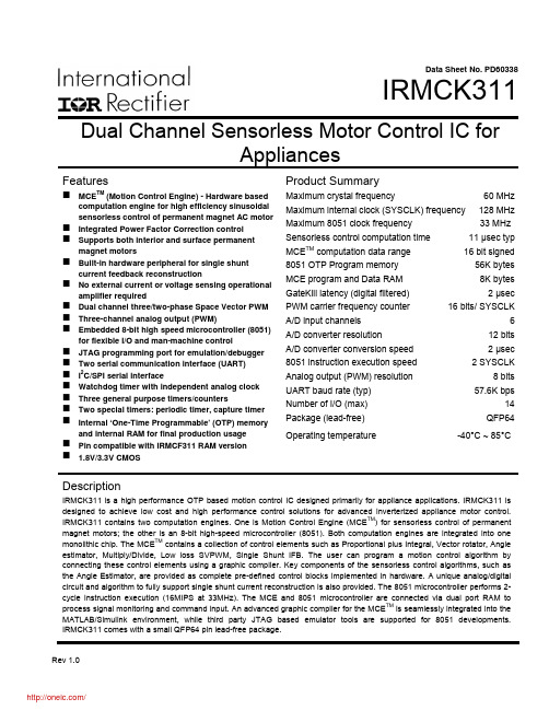
Data Sheet No. PD60338IRMCK311 Dual Channel Sensorless Motor Control IC forAppliancesFeaturesMCE TM (Motion Control Engine) - Hardware based computation engine for high efficiency sinusoidal sensorless control of permanent magnet AC motor Integrated Power Factor Correction controlSupports both interior and surface permanent magnet motorsBuilt-in hardware peripheral for single shunt current feedback reconstructionNo external current or voltage sensing operational amplifier requiredDual channel three/two-phase Space Vector PWM Three-channel analog output (PWM)Embedded 8-bit high speed microcontroller (8051) for flexible I/O and man-machine controlJTAG programming port for emulation/debugger Two serial communication interface (UART)I2C/SPI serial interfaceWatchdog timer with independent analog clockThree general purpose timers/countersTwo special timers: periodic timer, capture timer Internal ‘One-Time Programmable’ (OTP) memory and internal RAM for final production usagePin compatible with IRMCF311 RAM version1.8V/3.3V CMOS Product SummaryMaximum crystal frequency 60 MHz Maximum internal clock (SYSCLK) frequency 128 MHz Maximum 8051 clock frequency 33 MHz Sensorless control computation time 11 μsec typ MCE TM computation data range 16 bit signed 8051 OTP Program memory 56K bytes MCE program and Data RAM 8K bytes GateKill latency (digital filtered) 2 μsec PWM carrier frequency counter 16 bits/ SYSCLK A/D input channels 6 A/D converter resolution 12 bits A/D converter conversion speed 2 μsec 8051 instruction execution speed 2 SYSCLK Analog output (PWM) resolution 8 bits UART baud rate (typ) 57.6K bps Number of I/O (max) 14 Package (lead-free) QFP64 Operating temperature -40°C ~ 85°CDescriptionIRMCK311 is a high performance OTP based motion control IC designed primarily for appliance applications. IRMCK311 is designed to achieve low cost and high performance control solutions for advanced inverterized appliance motor control. IRMCK311 contains two computation engines. One is Motion Control Engine (MCE TM) for sensorless control of permanent magnet motors; the other is an 8-bit high-speed microcontroller (8051). Both computation engines are integrated into one monolithic chip. The MCE TM contains a collection of control elements such as Proportional plus Integral, Vector rotator, Angle estimator, Multiply/Divide, Low loss SVPWM, Single Shunt IFB. The user can program a motion control algorithm by connecting these control elements using a graphic compiler. Key components of the sensorless control algorithms, such as the Angle Estimator, are provided as complete pre-defined control blocks implemented in hardware. A unique analog/digital circuit and algorithm to fully support single shunt current reconstruction is also provided. The 8051 microcontroller performs 2-cycle instruction execution (16MIPS at 33MHz). The MCE and 8051 microcontroller are connected via dual port RAM to process signal monitoring and command input. An advanced graphic compiler for the MCE TM is seamlessly integrated into the MATLAB/Simulink environment, while third party JTAG based emulator tools are supported for 8051 developments. IRMCK311 comes with a small QFP64 pin lead-free package.TABLE OF CONTENTS1 Overview (5)2 IRMCK311 Block Diagram and Main Functions (6)3 Pinout (8)4 Input/Output of IRMCK311 (9)4.1 8051 Peripheral Interface Group (10)4.2 Motion Peripheral Interface Group (10)4.3 Analog Interface Group (11)4.4 Power Interface Group (11)4.5 Test Interface (12)5 Application Connections (13)6 DC Characteristics (14)6.1 Absolute Maximum Ratings (14)6.2 System Clock Frequency and Power Consumption (14)6.3 Digital I/O DC Characteristics (15)6.4 PLL and Oscillator DC Characteristics (15)6.5 Analog I/O DC Characteristics (16)6.6 Under Voltage Lockout DC Characteristics (17)6.7 AREF Characteristics (17)7 AC Characteristics (18)7.1 PLL AC Characteristics (18)7.2 Analog to Digital Converter AC Characteristics (19)7.3 Op Amp AC Characteristics (19)7.4 SYNC to SVPWM and A/D Conversion AC Timing (20)7.5 GATEKILL to SVPWM AC Timing (21)7.6 Interrupt AC Timing (21)7.7 I2C AC Timing (22)7.8 SPI AC Timing (23)7.8.1 SPI Write AC timing (23)7.8.2 SPI Read AC Timing (24)7.9 UART AC Timing (25)7.10 CAPTURE Input AC Timing (26)7.11 JTAG AC Timing (27)7.12 OTP Programming Timing (28)8 I/O Structure (29)9 Pin List (32)Dimensions (35)10 Package11 Part Marking Information (36)Information (36)12 OrderingTABLE OF FIGURESFigure 1. Typical Application Block Diagram Using IRMCK311 (5)Figure 2. IRMCK311 Internal Block Diagram (6)Figure 3. IRMCK311 Pin Configuration (8)Figure 4. Input/Output of IRMCK311 (9)Figure 5. Application Connection of IRMCK311 (13)Figure 6. Clock Frequency vs. Power Consumption (14)Figure 7 Crystal oscillator circuit (18)Figure 8 Voltage droop of sample and hold (19)Figure 9 SYNC to SVPWM and A/D conversion AC Timing (20)Figure 10 GATEKILL to SVPWM AC Timing (21)Figure 11 Interrupt AC Timing (21)Figure 12 I2C AC Timing (22)Figure 13 SPI AC Timing (23)Figure 14 SPI Read AC Timing (24)Figure 15 UART AC Timing (25)Figure 16 CAPTURE Input AC Timing (26)Figure 17 JTAG AC Timing (27)Figure 18 OTP Programming Timing (28)Figure 19 All digital I/O except motor PWM output (29)Figure 20 RESET, GATEKILL I/O (29)Figure 21 Analog input (30)Figure 22 Analog operational amplifier output and AREF I/O structure (30)Figure 23 VPP programming pin I/O structure (30)Figure 24 VSS and AVSS pin structure (31)Figure 25 VDD1 and VDDCAP pin structure (31)Figure 26 XTAL0/XTAL1 pins structure (31)TABLE OF TABLESTable 1. Absolute Maximum Ratings (14)Table 2. System Clock Frequency (14)Table 3. Digital I/O DC Characteristics (15)Table 4. PLL DC Characteristics (15)Table 5. Analog I/O DC Characteristics (16)Table 6. UVcc DC Characteristics (17)Table 7. AREF DC Characteristics (17)Table 8. PLL AC Characteristics (18)Table 9. A/D Converter AC Characteristics (19)Table 10. Current Sensing OP Amp AC Characteristics (19)Table 11. SYNC AC Characteristics (20)Table 12. GATEKILL to SVPWM AC Timing (21)Table 13. Interrupt AC Timing (21)Table 14. I2C AC Timing (22)Table 15. SPI Write AC Timing (23)Table 16. SPI Read AC Timing (24)Table 17. UART AC Timing (25)Table 18. CAPTURE AC Timing (26)Table 19. JTAG AC Timing (27)Table 20. OTP Programming Timing (28)Table 21. Pin List (32)1 OverviewIRMCK311 is a new International Rectifier integrated circuit device primarily designed as a one-chip solution for complete inverter controlled appliance dual motor control applications. Unlike a traditional microcontroller or DSP, the IRMCK311 provides a built-in closed loop sensorless control algorithm using the unique Motion Control Engine (MCE TM) for permanent magnet motors. The MCE TM consists of a collection of control elements, motion peripherals, a dedicated motion control sequencer and dual port RAM to map internal signal nodes. IRMCK311 also employs a unique single shunt current reconstruction circuit to eliminate additional analog/digital circuitry and enables a direct shunt resistor interface to the IC. The sensorless control is the same for both motors with a single shunt current sensing capability. Motion control programming is achieved using a dedicated graphical compiler integrated into the MATLAB/Simulink TM development environment. Sequencing, user interface, host communication, and upper layer control tasks can be implemented in the 8051 high-speed 8-bit microcontroller. The 8051 microcontroller is equipped with a JTAG port to facilitate emulation and debugging tools. Figure 1 shows a typical application schematic using IRMCK311.IRMCK311 is intended for volume production purpose and contains 64K bytes of OTP (One Time Programming) ROM, which can be programmed through a JTAG port. For a development purpose use, IRMCF311 contains a 48k byte of RAM in place of program OTP to facilitate an application development work. Both IRMCF311 and IRMCK311 come in the same 64-pin QFP package with identical pin configuration to facilitate PC board layout and transition to mass productionFigure 1. Typical Application Block Diagram Using IRMCK3112 IRMCK311 Block Diagram and Main FunctionsM o t i o n C o n t r o l B u sFigure 2. IRMCK311 Internal Block DiagramIRMCK311 contains the following functions for sensorless AC motor control applications:• Motion Control Engine (MCE TM )o Proportional plus Integral block o Low pass filtero Differentiator and lag (high pass filter) o Ramp o Limito Angle estimate (sensorless control) o Inverse Clark transformation o Vector rotator o Bit latch o Peak detect o Transitiono Multiply-divide (signed and unsigned)o Divide (signed and unsigned)o Addero Subtractoro Comparatoro Countero Accumulatoro Switcho Shifto ATAN (arc tangent)o Function block (any curve fitting, nonlinear function)o16-bit wide Logic operations (AND, OR, XOR, NOT, NEGATE)o MCE TM program and data memory (6K byte). Note 1o MCE TM control sequencer• 8051 microcontrollero Three 16-bit timer/counterso16-bit periodic timero16-bit analog watchdog timero16-bit capture timero Up to 36 discrete I/Oso Eleven-channel 12-bit A/DFive buffered channels (0 – 1.2V input)One unbuffered channel (0 – 1.2V input)o JTAG port (4 pins)o Up to three channels of analog output (8-bit PWM)o Two UARTo I2C/SPI porto 64K byte Note 1program One-Time Programmable memoryo2K byte data RAM. Note 2Note 1: Total size of OTP memory is 64K byte, however MCE program occupiesmaximum 8K byte which will be loaded into internal RAM at a powerup/bootprocess. Therefore only 56K byte OTP memory area is usable for 8051microcontroller.Note 2: Total size of RAM is 8K byte including MCE program, MCE data, and 8051data. Different sizes can be allocated depending on applications.3 PinoutXTAL0XTAL1P1.1/RXD P1.2/TXDVDD1VSS VDD2P1.3/SYNC/SCKP1.4/CAPP 3.6/R X D 1P 3.7/T X D 1FPWMVL FPWMUL V S SV D D 2A V D DA V S SA I N 0A R E FP 2.7/A O P W M 1P 2.6/A O P W M 0CPWMUH CPWMVH CPWMWH CPWMUL CPWMVL CPWMWL CGATEKILL VDD1VSS I F B C OI F B C +I F B C -P L L V S SP L L V D DR E S E TN CT C KP 5.3/T D IP 5.2/T D OP 5.1/T M SS D A /C S 0S C L /S O -S I /V P PP 5.0/P F C G K I L LP F C P W M V S SFGATEKILL FPWMWL VAC-VAC+VACO IPFCO IPFC+IPFC-I F B F OI F B F +I F B F -P3.0/INT2/CS1C M E X TFPWMVH FPWMUHFPWMWH A I N 1P 3.2/I N T 0Figure 3. IRMCK311 Pin Configuration4 Input/Output of IRMCK311All I/O signals of IRMCK311 are shown in Figure 4. All I/O pins are 3.3V logic interface except A/D interface pins.Figure 4. Input/Output of IRMCK3114.1 8051 Peripheral Interface GroupUART InterfaceP1.1/RXD Input, Receive data to IRMCK311, can be configured as P1.1P1.2/TXD Output, Transmit data from IRMCK311, can be configured as P1.22nd channel Receive data to IRMCK311, can be configured as P3.6 P3.6/RXD1 Input,P3.7/TXD1 Output,2nd channel Transmit data from IRMCK311, can be configured as P3.7Discrete I/O InterfaceP1.3/SYNC/SCK Input/output port 1.3, can be configured as SYNC output or SPI clock P1.4/CAP Input/output port 1.4, can be configured as Capture Timer inputP3.0/INT2/CS1 Input/output port 3.0, can be configured as external interrupt 2 or SPIchip select 1P3.2/INT0 Input/output port 3.2, can be configured as external interrupt 0Analog Output InterfaceP2.6/AOPWM0 Input/output, can be configured as 8-bit PWM output 0 withprogrammable carrier frequencyP2.7/AOPWM1 Input/output, can be configured as 8-bit PWM output 1 withprogrammable carrier frequencyCrystal InterfaceXTAL0 Input, connected to crystalXTAL1 Output, connected to crystalReset InterfaceRESET Inout, system reset, needs to be pulled up to VDD1 but doesn’t requireexternal RC time constantI2C/SPI InterfaceSCL/SO-SI/VPP Output, I2C clock output, SPI SO-SII2C Data line, Chip Select 0 of SPISDA/CS0 Input/output,P3.0/INT2/CS1 Input/output port 3.0, can be configured as external interrupt 2 or SPIchip select 1P1.3/SYNC/SCK Input/output port 1.3, can be configured as SYNC output or SPI clock 4.2 Motion Peripheral Interface GroupPWMCPWMUH Output, motor 1 PWM phase U high side gate signalCPWMUL Output, motor 1 PWM phase U low side gate signalCPWMVH Output, motor 1 PWM phase V high side gate signalCPWMVL Output, motor 1 PWM phase V low side gate signalCPWMWH Output, motor 1 PWM phase W high side gate signalCPWMWL Output, motor 1 PWM phase W low side gate signalFPWMUH Output, motor 2 PWM phase U high side gate signalFPWMUL Output, motor 2 PWM phase U low side gate signal分销商库存信息: IRIRMCK311TR。

ST1802HI
HIGH VOLTAGE FAST-SWITCHING
NPN POWER TRANSISTOR
s NEW SERIES, ENHANCED PERFORMANCE s
FULLY INSULATED PACKAGE (PLIANT) FOR EASY MOUNTING s HIGH VOLTAGE CAPABILITY (> 1500 V)s HIGH SWITCHING SPEED s TIGTHER hfe CONTROL s
IMPROVED RUGGEDNESS
APPLICATIONS: s HORIZONTAL DEFLECTION FOR COLOR TVs UP TO 25 INCHES DESCRIPTION The device is manufactured using Diffused Collector Technology for more stable operation Vs base drive circuit variations resulting in very low worst case dissipation.
®
December 2002 ABSOLUTE MAXIMUM RATINGS
1/6
s P
r o
d u c t () -
l s l
O
b s
o e t e
P
r o
d u c t () -
O b
s o e THERMAL DATA
ELECTRICAL CHARACTERISTICS (T case = 25 o C unless otherwise specified)
Safe Operating Area
Thermal Impedance
ST1802HI
l s l c )O
b s
o
e t e
P
r o
d u c t () -
O b
s o e t e
P r o
d u t (s
Derating Curve
Collector Emitter Saturation Voltage DC Current Gain
Output Characteristics
Base Emitter Saturation Voltage
DC Current Gain
ST1802HI
l c )r -
O b
s o e t e
P r o
d u t (s
Power Losses At 16 KHz
Figure 1 : Inductive Load Switching Test Circuit.
Switching Time Inductive Load
Reverse Biased SOA
ST1802HI
ST1802HI
l s l c )O
b s
o e t e
P
r o
d u c t () -
O b
s o e t e
P r o
d u t (s
Information furnished is believed to be accurate and reliable. However, STMicroelectronics assumes no responsibility for the consequences
of use of such information nor for any infringement of patents or other rights of third parties which may result from its use. No license is granted by implication or otherwise under any patent or patent rights of STMicroelectronics. Specification mentioned in this publication are subject to change without notice. This publication supersedes and replaces all information previously supplied. STMicroelectronics products are not authorized for use as critical components in life support devices or systems without express written approval of STMicroelectronics.
The ST logo is a trademark of STMicroelectronics © 2002 STMicroelectronics – Printed in Italy – All Rights Reserved
STMicroelectronics GROUP OF COMPANIES
Australia - Brazil - Canada - China - Finland - France - Germany - Hong Kong - India - Israel - Italy - Japan - Malaysia - Malta - Morocco - Singapore - Spain - Sweden - Switzerland - United Kingdom - United States.
ST1802HI
分销商库存信息: STM
ST1802HI。