K4D623238B-GC60中文资料
- 格式:pdf
- 大小:154.90 KB
- 文档页数:17

淮南矿业(集团)有限责任公司潘三矿主井装载站给煤机技术规格书编制:审核:单位负责人:机电办:矿领导:二0一三年一月九日一、项目情况1、项目名称:潘三矿主井装载站给煤机2、使用地点:潘三矿主井装载站二、技术规格1、设备型号:GLW1200(D,P)往复式给煤机 2套2、配套电机电压660V,功率18.5kw,转速970r/min,减速器速比15.753、生产能力满足300~1000t/h连续可调三、制造标准及技术要求1、设备的制造应符合国家标准或行业、国际标准。
2、设备在正常工作条件下,技术参数应能达到标称值。
3、给煤机电机与减速机联接应牢固可靠,安装平台主要构件采用工字钢。
减速机采用国产优质产品,密封件采用进口件,保证运行时不发生漏油和窜轴现象。
4、给煤机给料范围在300~1000吨/小时连续可调;后斜板采用厚度16mm的16MnCu钢板加一层衬板焊接加固,并保证牢固可靠,同时加用筋板加固。
侧板和底板另敷一层16mm的16MnCu钢板加固。
给煤机曲拐轴承及减速机轴承采用优质轴承。
5、给煤机与煤仓接口尺寸及给煤机安装尺寸由厂家按老式K4给煤机确定,具体由厂家现场测量确定。
6、厂家在供应给煤机时,随机提供出厂合格证,煤安标志及维护使用说明书,并在说明书中注明曲拐轴承及减速机轴承型号,上述资料一机两份。
7、给煤机的防腐采用两底一面,并按照工业品表面喷涂与防腐规定执行,应达到长效防腐要求。
8、主要钢板材料材质采取16MnCu钢,周边厚度大于等于12mm;9、安装时厂家派技术人员指导安装并免费提供技术培训。
10、设备出厂时,应带有设备总图(含电子版)、合格证、探伤报告、煤安标志、发货清单等技术文件。
四、供货范围1、GLW1200(D,P)往复式给煤机2套,包括。
平台的电机、减速器。
2、厂家还需提供曲拐机构两套,以作备用五、供货时间2013年5月1日前(送到潘三矿内)。


IN 47076July 1993Applicable additional manuals: SM61524 SM60554I nstallation I nstructionsC arter Brand Hydrant Valve Model 61524 or 60554I nto 12 Inch A very H ardoll P its W ith 3 Inch ANSI I ntermediary F langesPart Number 47076Aerospace GroupConveyance Systems DivisionCarter ® Brand Ground Fueling EquipmentTABLE OF CONTENTSPAGE1.0 INTRODUCTION (3)DESCRIPTION (3)2.0 EQUIPMENT3.0 INSTALLATION (3)2Installation InstructionsEaton's Carter brand Hydrant Valves into 12" Avery Hardoll Pits with 3 Inch ANSI Intermediary Flanges1.0 INTRODUCTIONThis manual furnishes detailed instructions covering the installation of either a Carter brand Model 61524DN, EN, 60554DN or EN Hydrant Valve into an Avery Hardoll pitwith a 3 inch ANSI intermediary flange. It should be used with Kit KD47076. Related service manuals covering the hydrant valves that are being installed are available from your local Carter brand distributor.60554 Hydrant Valve - SM6055461524 Hydrant Valve - SM615242.0 EQUIPMENTDESCRIPTION2.1 DESCRIPTIONCarter brand hydrant valves 61524DN, EN,60554DN or EN all have 4 inch ANSI inletflanges and include a set of parts designedto mate this inlet flange with the existing 3 inchANSI intermediary flange found in 12 inchAvery Hardoll pits. The mating parts includea spool adapter (3 x 4 inch) and two wedgeshaped spacers for use in leveling thespool in pits that have experienced pipemovement such that the pipe outlet is nolonger level with the ground. Also includedin the kit of parts are the four bolts used tomount the spool to the 3 inch ANSI pit flange,several O-rings, a gasket and studs, nutsand washers needed to install the hydrantvalve to the 4 inch flange of the spool adapter.2.2 INSTALLATION KIT, KD47076In addition to this manual a minimum of onekit, KD47076 is recommended for use toassist in installing the spool adapter andother parts of the inlet. One KD47076 isincluded with each order of either 61524DNor 60554DN Hydrants. If additional kits aredesired they can be purchased from yourlocal Carter brand distributor.3.0 INSTALLATION3.1 Remove the old valve from the pit beingsure to remove all parts down to the 3"intermediary flange. This flange should bepermanently affixed to the inlet piping.Clean this flange to remove all traces of dirtor pieces of gasket. Check the flange forthe presence of a groove for an o-ring sealof approximately 2.75 inches (70 mm)diameter. If such a groove is present areplacement o-ring is provided with theAdapter Assembly, 47076 or 47077. If nosuch groove is present, the gasket asprovided will be used to seal between thewedge shaped spacer and the intermediaryflange. (One, either the o-ring or the gasketwill be discarded).3.2 Install the eight s tuds furnished into thethreaded holes in the large end flange ofthe s pool a dapter. The s tuds should beinstalled until the entering end isapproximately flush with the lower surfaceof the flange.3.3 Place a leveling device on the intermediaryflange and check to see if it is level. If it islevel, continue on to paragraph 3.5. If it isnot level, continue on to paragraph 3.4. SeeStep 1 figure.3.4 Refer to Step 2 figure. Install the four 8"long studs from KD47076 by hand into thefour mounting holes in the intermediaryflange. These are used as a guide only andneed not be installed more than three orfour turns each. Place the O-ring(MS29513-237) in the groove in theintermediary flange (if groove is present). Ifthere is no groove, place the gasket ontothe flange over the four studs. If the hydrantvalve to be installed is a 61524DN or EN 4x 2½ inch unit, the two wedge shaped spacersprovided will be the same. If the unit to beinstalled is a 60554DN or EN 4 x 4" unit,one wedge shaped spacer will be thickerthan the other. Refer to Step 3 figure.One wedge shaped spacer (the thin one onthe 60554DN or EN) will be placed onto thegasket or o-ring with the grooved sideupwards. Insert the O-ring (MS29513-232)into the groove. The second spacer will be3placed on top of the first with the groovedside upwards. Note: If the spacers are ofdifferent thickness, as in the installation ofthe 60554 Hydrant, always place the thickerspacer on top. Put the level onto the top ofthe upper spacer (leave the o-ring out ofthe groove on the top spacer for the timebeing). See Step 4 figure. Rotate one orboth of the spacers until the top surface islevel. Remove the level, insert the secondO-ring (MS29513-232) into the groove. Skipto paragraph 3.6.3.5 If the intermediary flange of the pit is level,the two wedged shaped spacers will beinstalled such that the thick edge of one isopposite the thin edge of the other to keepthe flange level. Install the four eight inchlong studs into the intermediary flangefinger tight (three or four turns is sufficient).The O-ring (MS29513-237) will be placed inthe groove in the intermediary flange (or thegasket whichever is needed). The smallerO-ring (MS29513-232) will be installed inone spacer groove and the spacer isplaced onto the flange with the smooth sidedown against the o-ring or gasket. Thesecond wedged shaped spacer is placedsuch that the upper surface is level. Installthe second O-ring (MS29513-232) into thegroove. Note: If the spacers are of differentthickness, as in the installation of the 60554Hydrant, always place the thicker spacer ontop.3.6 Refer to Step 5 figure. Install the SpoolAdapter onto the four studs. Remove one ofthe studs and replace with one of the fourmounting Bolts (GF16997-171) andWashers (5712-403-63) provided. Use thelong Adapter (Allen Key) (220347),contained in KD47076, to run the Bolt downpart way. Do not tighten at this time.Repeat with the other three Bolts, removingeach stud in turn. Tighten one Bolt until itseats only. Tighten the other three untilthey seat only. Looking at the four boltpattern, number (mentally) them 1, 2, 3 and4 in a clockwise fashion. Torque number 1to 80 ft-lb (11 kg-m) followed by number 3,2 and 4 in that order. Repeat the torquing to110 ± 10 ft-lb (15.2 ± 1.4 kg-m) in the samepattern, then check the torque to the samevalue in the bolt order 1, 2, 3 and 4.After the bolts are torqued, use the levelingdevice to insure the upper surface of theadapter is level. Make necessaryadjustments as necessary.3.7 Install the largest O-ring (MS29513-246)into the groove in the Spool Adapter.Note: The installation so far should be "off-center" with respect to the inside diameterof the pit. The Hydrant Valve should beoriented during installation such that thepilot valve (lanyard attached) is locatedaway from the off-set to assure themaximum amount of room for operation.Install the Hydrant Valve, taking intoaccount the off-set discussed above, ontothe unit and install the eight Washers(GF960-1016) and Nuts (82156) hand tight.Using a crowfoot type open end wrench,tighten all nuts to seat them in place.Mentally number the eight nuts 1 through 8clockwise. Tighten number one to 80 ft-lb(11 kg-m) followed by numbers 5, 3, 7, 2, 6,4 and 8. Then torque to 110 ± 10 ft-lb (15.2± 1.4 kg-m) in the same pattern, then checkthe torque to the same value in the boltorder 1 thru 8 sequentially.3.8 Once the hydrant valves are installed theunits can be removed from the pit byremoving the eight nuts and the SpoolAdapters can be left in the pit. The O-ring(MS29513-246) should be replaced eachtime the valves are removed.4Aerospace Group Conveyance Systems Division 9650 Jeronimo RdIrvine, CA 92618Ph (949) 452-9500Fax (949) 452-9992。

多绳摩擦式提升机1958年中信重型机械公司(原洛阳矿山机器厂)开始自行设计多绳摩擦式提升机,1960年第一台多绳摩擦式提升机DJ2×4在辽宁阜新五龙矿东风井投入运行,并编制了我国第一个多绳摩擦式提升机系列,并于1965年由机械部洛阳矿山机械研究所负责编制了多绳摩擦式提升机部颁标准,从此开创了我国塔式多绳摩擦式提升机的设计生产历史,根据我国能源工业对落地多绳摩擦式提升机的需求,1977年中信重型机械公司设计试制了我国第一台2×2落地多绳摩擦式提升机,此后落地多绳摩擦式提升机得到了广泛的应用和发展。
经过公司科研技术人员的不断努力和探索,特别是对引进技术的消化吸收和创新。
多绳摩擦式提升机经历了五次更新换代,从而形成了现行的具有当今国际先进水平的多绳摩擦式提升机系列。
截止目前中信重型机械公司和洛阳矿山机械研究所共设计制造了600多台多绳摩擦式提升机。
设计制造了亚洲最大的JKMD-5.7×4(Ⅲ)、JKM-4×6(Ⅲ)多绳摩擦式提升机。
多绳摩擦式提升机结构特点多绳摩擦式提升机从布置型式分落地和井塔两种,从传动结构型式分Ⅰ、Ⅱ、Ⅲ、Ⅳ:多绳摩擦式提升机的结构特点:1.主轴装置是多绳摩擦式提升机的关键部件,根据多绳摩擦式提升机的参数及所配制动器不同有单闸盘和双闸盘之分。
落地多绳摩擦式提升机其摩擦衬垫为双绳槽,并配有过渡装置。
塔式为单绳槽。
摩擦衬垫在无油、淋水或使用专用脂条件下摩擦系数为0.23、0.25两种,全部采用酚醛塑脂固定块、压块。
2.天轮装置和导向轮装置,采用偏心布置,在轮子上装有PVC或尼龙衬垫。
3.盘形制动器和液压站,液压站分中低压和中高压两种类型,中低压液压站有恒制动力电气延时和液压延时两种二级制动供用户选择。
中高压有恒减速度液压站和恒制动力二级制动液压站;其中因电控需要部分液压站装有压力继电器和压力传感器以及压力变送器。
4.测速传动及后备保护,配套提供闸盘偏摆监测装置、钢丝绳滑动监测装置、车槽装置、专用工具等部件。

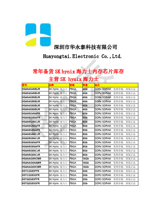
从内存条芯片编号看内存条的大小SDRAM 内存芯片的新编号A字段由HY组成,代表现代(Hynix)内存芯片的前缀。
B字段表示产品类型。
57代表SDRAM内存。
C字段表示工作电压。
V代表VDD电压为3.3V、VDDQ电压为3.3V;Y代表VDD电压为3.0V、VDDQ电压为3.0v;U代表VDD电压为2.5V、VDDQ电压为2.5V;W代表VDD电压为2.5V、VDDQ电压为1.8V;S代表VDD电压为1.8V、VDDQ电压为1.8V/ D字段表示密度与刷新速度。
16代表16Mbit密度、2K刷新速度;32代表32Mbit密度、4K刷新速度;64代表64Mbit密度、4K刷新速度;28代表128Mbit密度、4K刷新速度;2A代表128Mbit密度(TCSR)、4K刷新速度;56代表256Mbit密度、8K刷新速度;12代表512Mbit密度、8K刷新速度。
E字段表示内存结构。
4代表x4;8代表x8;16代表x16 ;32代表x32。
F字段表示内存芯片内部由几个Bank组成。
1代表2Bank;2代表4Bank。
G字段表示电气接口。
0代表LVTTL;1代表SSTL_3。
H字段表示内存芯片的修正版本。
空白或H代表第1版;A或HA代表第2版;B或HB代表第3版;C或HC代表第4版。
也有一些特殊的编号规则,如:编号为HY57V64420HFT是第7版;编号为HY57V64420HGT和HY57V64820HGT是第8版;编号为HY57V28420AT是第3版;编号为HY57V56420HDT是第5版。
I字段表示功率消耗能力。
空白代表正常功耗;L代表代功耗;S代表超代功耗。
J字段表示内存芯片的封装方式。
T代表TSOP封装;K代表Stack封装(Type1);J代表Stack封装(Type2)。
K字段表示内存芯片的封装材料。
空白代表正常;P代表Pb free;H代表Halogen free;R代表Pb & Halogen free。
![[讲解]火箭SAS阵列卡参数](https://img.taocdn.com/s1/m/bbe8b13f905f804d2b160b4e767f5acfa1c78313.png)

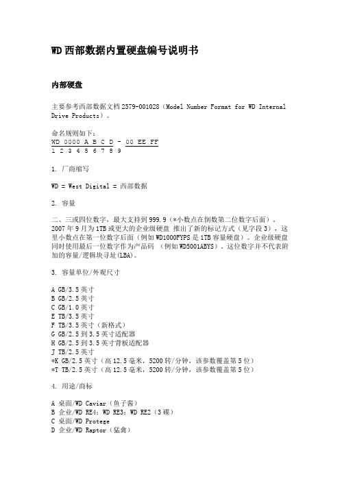
WD西部数据内置硬盘编号说明书内部硬盘主要参考西部数据文档2579-001028(Model Number Format for WD Internal Drive Products)。
命名规则如下:WD 0000 A B C D - 00 EE FF1 2 3 4 5 6 7 8 91. 厂商缩写WD = West Digital = 西部数据2. 容量二、三或四位数字,最大支持到999.9(*小数点在倒数第二位数字后面)。
2007年9月为1TB或更大的企业级硬盘推出了新的标记方式(见字段3),这里小数点在第一位数字后面(例如WD1000FYPS是1TB容量硬盘)。
企业级硬盘同时使用最后一位数字作为产品码(例如WD5001ABYS)。
这位数字并不代表附加的容量/逻辑块寻址(LBA)。
3. 容量单位/外观尺寸A GB/3.5英寸B GB/2.5英寸C GB/1.0英寸E TB/3.5英寸F TB/3.5英寸(新格式)G GB/2.5到3.5英寸适配器H GB/2.5到3.5英寸背板适配器J TB/2.5英寸*K GB/2.5英寸(高12.5毫米,5200转/分钟,该参数覆盖第5位)*T TB/2.5英寸(高12.5毫米,5200转/分钟,该参数覆盖第5位)4. 用途/商标A 桌面/WD Caviar(鱼子酱)B 企业/WD RE4;WD RE3;WD RE2(3碟)C 桌面/WD ProtegeD 企业/WD Raptor(猛禽)E 移动/WD ScorpioH 发烧/WD Raptor XJ 移动/WD Scorpio FFS(带自由落体感应)K 企业/WD S25L 企业/WD VelociRaptor(迅猛龙)M 品牌/WD Branded*P 移动/WD Scorpio(高级格式化)*U 影音/WD AV(和V有什么区别?好奇ing)V 影音/WD AVY 企业/ WD RE4;WD RE3;WD RE2(4碟)*Z 桌面/WD Caviar(GPT分区)5. 转速/缓存大小或属性A 5400转/分钟,2MB缓存B 7200转/分钟,2MB缓存C 5400转/分钟,16MB缓存D 5400转/分钟,32MB缓存E 7200转/分钟,64MB缓存(<2TB)F 10,000转/分钟,16MB缓存G 10,000转/分钟,8MB缓存H 10,000转/分钟,32MB缓存J 7200转/分钟,8MB缓存K 7200转/分钟,16MB缓存L 7200转/分钟,32MB缓存P IntelliPower,EM(最大缓存由产品决定)R 5400转/分钟,64MB缓存S 7200转/分钟,64MB缓存(2TB)V 5400转/分钟,8MB缓存(移动产品)Y 7200转/分钟,EM(最大缓存由产品决定)6. 接口/连接部件A ATA/66,40针IDE连接器B ATA/100,40针IDE连接器C ATA,33针连接器(零插入力——ZIF)D SATA 1.5Gb/秒,22针SATA连接器E ATA/133,40针IDE连接器F SAS-3,29针连接器G SAS-6,29针连接器S SATA 3Gb/秒,22针SATA连接器SATA 1.5Gb/秒,22针SATA连接器(移动产品)T SATA 3Gb/秒,22针SATA连接器(移动产品)X SATA 6Gb/秒,22针SATA连接器(*或者SATA 3Gb/秒,对于RE4来说)*以下为后缀号,内部数据。


(川崎k3vg样本)kawasa...FeaturesReliable, High Pressure, Long Life Modular Design.Low Noise and High Efficiency.Self-Compensating piston return mechanism. Extensive Range of Highly Responsive Control Options.Auxiliary Gear Pump Option.Rated Pressure 350 Bar.? Peak Pressure 400 Bar.High Continuous Power Rating.Fully Balanced Spherical Valve Plate.Infinite displacement control.Hydrostatically Balanced Swash Plate Support. ? High Load Capacity Bearings.General DescriptionTechnical DataFor applications outside the following parameters, please consult Kawasaki Precision Machinery (UK) Ltd.Hydraulic DataPressure Fluid Mineral oil, phosphate ester, fatty acid ester and water glycol.Phosphate ester is only suitable for use with FPM seals.Use a high quality, anti-wear, mineral based hydraulic fluid whenthe pressure exceeds 207 bar. In applications where fire resistantfluids are required consult Kawasaki Precision Machinery (UK) Ltd.The following chart illustrates the effects on pump life when non-standard fluids are used:FluidTypeMineral Oil Phosphate Ester Polyol EsterWater Glycol*Maximum continuousPressure (bar)350 207 Temperature Range (°C) -20 ~ +80 0 ~ +60 0 ~ +60 10~50Cavitation Resistance # ? ? ?Percentage pump lifecompared to mineral oil100 60~100 50~100 20~80# =Optimum= Acceptable but with reduced pump life*= DO NOT EXCEED THE RATED SPEED. Maximum speed for 280cc pumps using water glycol is 1500rpm.System cleanliness Maximum permissible degree of contamination of fluid is to NAS1638 class 9 or ISO 4466/1986 code 18/15. Kawasaki recommenda filter with a retention rate of ?10≥75.Viscosity Range Nominal operating range 10 to 200 cSt (For fluids over 200 cStcontact Kawasaki Precision Machinery (UK) Ltd).Model K3VG Page2.34Data SheetP-1001/06.99Technical Data (continued)For applications outside the following parameters, please consult Kawasaki Precision Machinery (UK) Ltd.PumpModel 63 112 180 280 180DT280DT Displacement cm3/rev 63 112 180 280 360 560Rated Pressure(1)bar 350 350 350 350 350 350Peak Pressure(2) bar 400 400 400 400 400 400RatedPower(kW) 70 125 200 255 405 510Max Flow(@ rated speed) l/min106 193 310 390 621 780Rated Speeds at suctionpressures >or = to -0.1 bar rpm1800 1800 1800 1500 1800 1500Maximum operating Speeds atsuction pressures >or = to +1 barrpm3250 2700 2300 2000 2300 2000Mass kg486886160160300 NOTES:(1) Pressure at which life and durability of the pump will not be affected.(2)Pressure at which functionality of pump is not affected butlife and durabilitywill be shortened. Please contact Kawasaki for recommendations.CAUTIONS!1. Make sure the pump case is filled with clean, filtered fluid of the type used in the system beforeoperation.2. The pump case must be full at all times to ensure lubrication of the internal components.3. When installing the tandem pumps (K3VG180DT and K3VG280DT) make sure that both the frontand rear pumps are filled with oil through both case drain ports.Model K3VG Page3.34Data SheetP-1001/06.99Summary of Control OptionsPower/Pressure Control Code Displacement Control CodeDescription0 P Infinitely variable positive displacement control by pilotpressure0 N Infinitely variable negative displacement control by pilotpressure0 E Infinitely variable positive displacement control by ElectricalProportional Valve1 0 Power control with maximum displacement stop1 P Power and positive displacement control by pilot pressure1 N Power and negative displacement control by pilot pressure1 E Power and positive electrical displacement control4 0Pressurecompensation4 LLoadsensecontrol7 0 Power and pressure compensation7 P Power, pressure compensation and positive displacementcontrol7 N Power, pressure compensation and negative displacementcontrol7 E Power, pressure compensation and electrical positivedisplacement control7 L Power control and Load sensing. (also available with acombined displacement control option)Note:When using displacement control at pump delivery pressures below 40bar, a pressure assist signal is required to maintain adequate response.The pressure assist signal can be provided by either an attached gear pump or an external source. The optional attached gear pump is recommended for use with all displacement control options.All displacement control hydraulic circuit diagrams illustrate the attached gear pump.Model K3VG Page6.34Data SheetP-1001/06.99。


新代盘式主轴电机选型手册匯出日期:2023-05-10修改日期:2023-04-25••••••••推广文件(Promotional Document)盘式电机规格(Disc Motor Specifications)简称定义(Abbreviation Definition)料号定义(Material Definition)盘式电机线材(Disc Motor Wires)尺寸图(Dimensions):支援的机械主轴(Supported Mechanical Spindle):支援的回转油缸(Supported Rotary Cylinder)电机规格(Motor Specifications)更新履历(Edited History)1 推广文件(Promotional Document)简体( CHS)繁体(CHT)盘式电机推广文件2022V1.pdf盤式電機推廣文件2021V7.pptx 盘式电机使用维护手册.pdf盘式电机安装流程.mp4盤式電機安裝視頻.mp41.2.3.2 盘式电机规格(Disc Motor Specifications)2.1 简称定义(Abbreviation Definition)DA5-52(盤式電機+主軸規格-扭力 Disc motor+spindle specification-torque )D 代表 盘式电机-D represents disc motor20/A4/A5/A6/A8"代表主轴规格-represent the spindle specifications 52 代表扭矩 52N-represents t orque2.2 料号定义(Material Definition)新简称new abbr eviat ion原简称orig in abb revi atio n 料号materi al no.额定功率rate d pow er (kw)S2功率S2 pow er (kw)额定扭力rated torqu e(nm)額定转速rated speed (rpm)最高转速maxim um speed (rpm)内径inner diam eter (mm)标配编码器型号standard encoder model搭配驱动器matc hed drive r 主轴s pi n dl eDA4-17DSP 11A 2S08-D8-084060CF1 5.37.95173000800060S08-GSKMY2-R-242-S SPD32C1-075SMH-25/25-75MA 2-4S08-D8-084062CF15.37.951730008000 62S08-GSKMY2-R-242-S DA4-20DSP 11BS08-D7-064060BF14.2 6.3202000600060S08-GSKMY2-R-242-SS08-D7-0640 62BF14.2 6.3202000600062S08-GSKMY2-R-242-SDA4-25DSP11CS08-D12-064060CF17.911.85253000600060S08-GSKMY2-R-242-SS08-D12-064062CF17.911.85253000600062S08-GSKMY2-R-242-SDA5-35DSP16AS08-D17-064065CF11116.5353000600065S08-GSKMY2-R-242-SSPD32D1-110SMH-35/35-100-MA2-5S08-D17-064070CF11116.5353000600070S08-GSKMY2-R-242-SS08-D17-064072CF11116.5353000600072S08-GSKMY2-R-242-SDA5-52DSP16BS08-D17-044065BF11116.5522000450065S08-GSKMY2-R-242-SS08-D17-044070BF11116.5522000450070S08-GSKMY2-R-242-SS08-D17-044072BF11116.5522000450072S08-GSKMY2-R-242-SDA6-57DSP21A1S08-D18-044085BF111.917.85572000400085S08-GSKMY2-326-SSPD32C1-110SMH-35/35-100-MA2-6S08-D18-044090BF111.917.85572000400090S08-GSKMY2-326-SDA6-72DSP21A2S08-D23-044085BF11522.5722000400085S08-GSKMY2-326-SSPD32C1-185SMH-35/35/35-100-XL S08-D23-044090BF11522.5722000400090S08-GSKMY2-326-SDA6-90DSP21A3S08-D22-044085AF114.121.15901500400085S08-GSKMY2-326-SSPD32C1-185S08-D22-044090AF114.121.15901500400090S08-GSKMY2-326-S3 盘式电机线材(Disc Motor Wires)新简称new abbreviation 料号material no.单独动力线接头single power cordconnector包套动力线线材(含接头)包套编码器线材(含接头)DA4-17S08-D8-084060CF1P03-CMS3108A22-4W01-S4-ML-PW-4MW01-S4-ML-PW-5MW01-S4-ML-PW-6MW01-PGSF-EN-*MS08-D8-084062CF1 DA4-20S08-D7-064060BF1S08-D7-064062BF1 DA4-25S08-D12-064060CF1S08-D12-064062CF1 DA5-35S08-D17-064065CF1S08-D17-064070CF1S08-D17-064072CF1 DA5-52S08-D17-044065BF1S08-D17-044070BF1S08-D17-064072CF11.2. a.i.ii.iii.iv.v.b.i.ii.iii.iv.v.DA6-57S08-D18-044085BF1W01-S6-ML-PW-4M W01-S6-ML-PW-5M W01-S6-ML-PW-6MS08-D18-044090BF1DA6-72S08-D23-044085BF1S08-D23-044090BF1DA6-90S08-D22-044085AF1S08-D22-044090AF1注:盘式电机出货默认不含线材和接头(note: Disc motors are shipped without wires and connectors by default)若客户自制动力线材,可以参考以下建议W01-S4-ML-PW-5M原材料线:W07-SP-PW-12AWG ((約4mm^2)针型压线端子:Z02-PTD5-13O 型压线端子:Z02-RDL5-4-O 线标:棕U 、黑V 、蓝W 、黄绿FG连接器:P03-CMS3108A22-4(L 型_大军规)W01-S6-ML-PW-5M原材料线:W07-SP-PW-10AWG (約6mm^2)针型压线端子:Z02-PTD5-13 O 型压线端子:Z02-RDL5-4-O 线标:棕U 、黑V 、蓝W 、黄绿FG连接器:P03-CMS3108A22-4(L 型_大军规)4 尺寸图(Dimensions):DA4内径60 DA4 inner diameter 60S08-D8-084060CF1S08-D7-064060BF1【2D外形图】DA4系列60内径.pdf【2D外形图】DA4系列60内径.dwg【3D外形图】DA4内径60.STEPS08-D12-064060CF1【3D外形图】DA4-25内径60.STEP系列+内径series+inner diameter 料号material no.PDF2D3D备注noteDA4内径62 DA4 inner diameter 62S08-D8-084062CF1S08-D7-064062BF1【2D外形图】DA4系列62内径.pdf【2D外形图】DA4系列62内径.dwg【3D外形图】DA4内径62.STEPS08-D12-064062CF1【3D外形图】DA4-25内径62.STEPDA5内径65 DA5 inner diameter 65S08-D17-064065CF1S08-D17-044065BF1【2D外形图】DA5系列65内径.pdf【2D外形图】DA5系列65内径.dwg【3D外形图】DA5系列65内径.STEPDA5内径70 DA5 inner diameter 70S08-D17-064070CF1S08-D17-044070BF1【2D外形图】DA5系列70内径.pdf【2D外形图】DA5系列70内径.dwg【3D外形图】DA5系列70内径.stepDA5内径72 DA5 inner diameter 72S08-D17-064072CF1S08-D17-044072BF1【2D外形图】DA5系列72内径.pdf【2D外形图】DA5系列72内径.dwg【3D外形图】DA5系列72内径.STEPDA4内径60 DA4 inner diameter 60S08-D8-084060CF1S08-D7-064060BF1【2D外形图】DA4系列60内径.pdf【2D外形图】DA4系列60内径.dwg【3D外形图】DA4内径60.STEPS08-D12-064060CF1【3D外形图】DA4-25内径60.STEP系列+内径series+inner diameter 料号material no.PDF2D3D备注noteDA6内径85 DA6 inner diameter 85S08-D18-044085BF1S08-D23-044085BF1S08-D22-044085AF1【2D外形图】DA6系列85内径.pdf【2D外形图】DA6系列85内径.dwg【3D外形图】DA6系列85内径.STEPDA6内径90 DA6 inner diameter 90S08-D18-044090BF1S08-D23-044090BF1S08-D22-044090AF1【2D外形图】DA6系列90内径.pdf【2D外形图】DA6系列90内径.dwg【3D外形图】DA6系列90内径.STEP5 支援的机械主轴(Supported Mechanical Spindle):兼容型号compatiblemodelDA4DA5DA6主轴内径(spindle innerdiameter)60626570728590罗翌(Royal)RA4007002-----------------------罗翌某型號 (acertain model ofRoyal)------昊志(Haozhi)DGZC-15006------A2-5-170---------普森(Posa)TAC-10------SJ-20------御成(Vyu Cheng)VA24150------------------------海纳(Haina)CK150A2-4------------------------健椿(Kenturn)------KT7006G KT1605NKT2004E6 支援的回转油缸(Supported Rotary Cylinder)油缸品牌cylinder brand 型号model回转油缸止口piston diameter回转油缸安装螺丝孔节径threaded holediameter是否与盘式电机兼容CompatibilityA2-4常州科普特Kepute(Changzhou)TK536100125compatible台湾千岛Chandox(Taiwan)F1036S100125compatibleA2-5台湾千岛Chandox(Taiwan)F1246S100147compatible常州科普特Kepute(Changzhou)TK646S100147compatible台湾三川Swachuaw(Taiwan)BK1246100147compatible台湾佳贺Autogrip(Taiwan)TK-B646100147compatible沈阳TGTTGT(Shenyang)TF-646100147compatibleA2-6常州科普特Kepute(Changzhou)TK852130165compatible台湾三川Swachuaw(Taiwan)BK1552130165compatible1. 2. 3. 4.油缸品牌cylinder brand型号model回转油缸止口piston diameter回转油缸安装螺丝孔节径threaded holediameter是否与盘式电机兼容Compatibility台湾佳贺Autogrip(Taiwan)TK-B853130165compatible沈阳TGTTGT(Shenyang)TF-852130165compatible项次修改记录日期撰写版本1编写初版20191120郭浩V1.0 2增加DSP11机型20200518郭浩V1.0 3仅保留富田机型20210601郭浩V2.0 4 改为上线之规格20211006郭浩V3.05DA5系列新增72内径,适配键椿主轴推广手册更新新增电机安装视频新增电机维护手册20210408郭浩V4.0电机规格(Motor Specifications)更新履历(Edited History)。

623轴承该资料是关于623轴承规格参数介绍、623轴承设计图、623轴承相关型号查询资料大全等。
623轴承规格参数:623轴承设计图品牌:瑞典SKF轴承类型:单列深沟球轴承型号:623轴承内径mm:3外径mm:10厚度mmm:4额定负荷KN:0.54(C)*0.18(C0)疲劳负荷限值KN:0.007额定速度r/min:130000极限转速r/min:80000质量Kg:0.0015挡肩及倒角尺寸(最大)mm:4.2d*8.8D*0.1r623轴承相关型号查询:轴承类型型号内径外径厚度轴承品牌深沟球轴承 623 3mm 10mm 4mm SKF深沟球轴承 623 3mm 10mm 4mm SKF深沟球轴承 623-Z 3mm 10mm 4mm SKF深沟球轴承 623-2Z 3mm 10mm 4mm SKF深沟球轴承 623 3mm 10mm 4mm SKF深沟球轴承 623-2Z 3mm 10mm 4mm SKF深沟球轴承 6238 190mm 340mm 55mm SKF深沟球轴承 6236 180mm 320mm 52mm SKF深沟球轴承 6236 180mm 320mm 52mm SKF深沟球轴承 6234 170mm 310mm 52mm SKF深沟球轴承 6234 170mm 310mm 52mm SKF深沟球轴承 6234 170mm 310mm 52mm SKF深沟球轴承 6232 160mm 290mm 48mm SKF深沟球轴承 6230 150mm 270mm 45mm SKF深沟球轴承 6230 150mm 270mm 45mm SKF深沟球轴承 609-Z 9mm 24mm 7mm SKF深沟球轴承 618/9 9mm 17mm 4mm SKF深沟球轴承 618/9 9mm 17mm 4mm SKF深沟球轴承 629 9mm 26mm 8mm SKF深沟球轴承 629-2Z 9mm 26mm 8mm SKF深沟球轴承 629-2RZ 9mm 26mm 8mm SKF深沟球轴承 629-2RS1 9mm 26mm 8mm SKF深沟球轴承 629-2Z 9mm 26mm 8mm SKF深沟球轴承 629-Z 9mm 26mm 8mm SKF深沟球轴承 629-RZ 9mm 26mm 8mm SKF深沟球轴承 609-2RZ 9mm 24mm 7mm SKF深沟球轴承 609-2Z 9mm 24mm 7mm SKF深沟球轴承 609-RS1 9mm 24mm 7mm SKF深沟球轴承 609-RZ 9mm 24mm 7mm SKF深沟球轴承 609-Z 9mm 24mm 7mm SKF深沟球轴承 609 9mm 24mm 7mm SKF深沟球轴承 609-2RS1 9mm 24mm 7mm SKF深沟球轴承 629 9mm 26mm 8mm SKF 深沟球轴承 629-2RS1 9mm 26mm 8mm SKF 深沟球轴承 629-2RZ 9mm 26mm 8mm SKF 深沟球轴承 629-2Z 9mm 26mm 8mm SKF 深沟球轴承 629-RS1 9mm 26mm 8mm SKF 深沟球轴承 629 9mm 26mm 8mm SKF 深沟球轴承 629-2Z 9mm 26mm 8mm SKF 深沟球轴承 629-RS1 9mm 26mm 8mm SKF 深沟球轴承 629-2RZ 9mm 26mm 8mm SKF 深沟球轴承 629-2RS1 9mm 26mm 8mm SKF 深沟球轴承 629-2Z 9mm 26mm 8mm SKF 深沟球轴承 629 9mm 26mm 8mm SKF 深沟球轴承 629-2RS1 9mm 26mm 8mm SKF 深沟球轴承 629-2RZ 9mm 26mm 8mm SKF 深沟球轴承 6019-2Z 95mm 145mm 24mm SKF 深沟球轴承 6019-RS1 95mm 145mm 24mm SKF 深沟球轴承 6019N 95mm 145mm 24mm SKF 深沟球轴承 6019-2RS1 95mm 145mm 24mm SKF 深沟球轴承 6019 95mm 145mm 24mm SKF 深沟球轴承 6019-RS1 95mm 145mm 24mm SKF 深沟球轴承 6019-2Z 95mm 145mm 24mm SKF 深沟球轴承 6019-Z 95mm 145mm 24mm SKF 深沟球轴承 6019N 95mm 145mm 24mm SKF 深沟球轴承 6219-2RS1 95mm 170mm 32mm SKF 深沟球轴承 6219-RS1 95mm 170mm 32mm SKF 深沟球轴承 6219-2Z 95mm 170mm 32mm SKF 深沟球轴承 6219-Z 95mm 170mm 32mm SKF 深沟球轴承 6219N 95mm 170mm 32mm SKF 深沟球轴承 6219-2Z 95mm 170mm 32mm SKF 深沟球轴承 6219-RS1 95mm 170mm 32mm SKF 深沟球轴承 6219N 95mm 170mm 32mm SKF 深沟球轴承 6219-Z 95mm 170mm 32mm SKF 深沟球轴承 61819-2RS1 95mm 120mm 13mm SKF 深沟球轴承 61819 95mm 120mm 13mm SKF 深沟球轴承 61819-2RZ 95mm 120mm 13mm SKF 深沟球轴承 61819-RS1 95mm 120mm 13mm SKF 深沟球轴承 61819-2RS1 95mm 120mm 13mm SKF 深沟球轴承 61819-RZ 95mm 120mm 13mm SKF。

安装及操作说明名称:透平压缩机系统型号:3(2)VRZ 250/430/16 G序言本安装和操作说明是对3(2)VRZ 250/430/16 G 型透平压缩机开车、操作、维修的重要描述。
因此,在初次开车前,你必须认真阅读安装和操作说明以及LCP的操作手册,已确保安全、经济的使用此透平压缩机。
压缩机的关键部件,例如电机、齿轮单元、油冷器、油过滤器、油泵等也必须遵守此操作说明。
所有的维修活动必须由相关的专家进行。
由于操作疏忽或者维修不当而造成的设备故障,我们将不接受任何质保要求。
我们将为你解决你在此安装和操作说明中遇到的任何问题。
我们希望你们能在不出现任何问题的情况下顺利运行这套系统。
目录表格清单 (6)图纸清单 (6)简介 (7)用途 (7)1.安全规程及说明 (8)1.1安全规程................................................................................. .8 1.2安全说明. (8)1.3重点 (10)2.技术资料 (11)2.1压缩机 (11)2.2与压缩机相连的冷却器............................................................. (16)2.2.1冷却器 (16)2.2.2连接管道 (16)2.2.3冷却器使用的弹簧垫圈........................................................ (16)2.3电机 (16)2.4增速器 (17)2.5联轴器 (17)2.6设备底座 (17)2.7润滑油系统 (18)2.7.1油箱 (18)2.7.2油冷却器 (18)2.7.2.1辅助油泵 (19)2.7.2.2油冷却器 (19)2.7.2.3油过滤器 (19)2.8设备底座、油系统和油冷却器的安装 (20)2.9消耗定额............................................................................. (20)2.9.1润滑油.......................................................................... (20)2.9.1.1过滤油量..................................................................... (20)2.9.1.2润滑油量.................................................. (21)2.9.2密封气.............................................. (22)2.9.3电力消耗....................................................................... (22)2.9.3.1压缩机电机.................................................................. (22)2.9.3.2辅助油泵电机 (22)2.9.3.3油箱加热器 (22)3.压缩机组的各部件名称及功能 (23)3.1压缩机.............................................. . (23)3.1.1压缩机的一般资料 (23)3.1.2设计说明 (27)3.1.2.1转子 (33)3.1.2.2机壳 (33)3.1.2.3导轮和迷宫密封.............................................. . (33)3.1.2.4压缩机转子轴承的安装 (33)3.1.3中冷器和后冷器 (34)3.2驱动系统 (34)3.2.1电机 (34)3.2.2增速器 (34)3.2.3联轴器 (34)3.3润滑油供应 (35)3.4测量和控制技术 (39)3.4.1测量点—密封—连锁........................................................ (39)3.4.2控制点 (39)3.4.2.1进口导叶 (39)3.4.2.2电涌调节 (39)3.4.2.3密封器调节 (40)3.4.3轴振动和径向位移 (40)4.压缩机组的安装 (41)4.1压缩机的安装 (41)4.2辅助单元的安装 (41)4.3铺设油、气、冷却水管线 (41)4.4校正 (42)4.4.1连接加速器和压缩机的联轴器的校正 (42)4.4.2连接电机和加速器的联轴器的校正 (44)5.压缩机装置的试车和操作 (46)5.1初次开车前的准备工作 (46)5.2初始试车 (48)5.2.1机械运转测试 (48)5.2.2操作测试 (48)5.3正常开车 (48)5.4投入氯气开车 (50)5.5停车 (51)5.5.1正常停车 (51)5.5.2故障停车 (52)5.6维护 (53)6.操作故障 (54)6.1主电机 (54)6.1.1主电机不启动 (54)6.1.2主电机停机 (54)6.2加速器 (54)6.2.1油循环温度太高 (54)6.2.2轴承温度太高 (54)6.2.3加速器内突然出现不正常运行噪音 (54)6.3压缩机 (55)6.3.1运行不稳定 (55)6.3.2所有轴承温度升高 (55)6.3.3某一个轴承温度升高 (55)6.3.4压缩机出口气体温度升高 (55)6.3.5密封气压力降低 (55)6.4润滑油系统 (55)6.4.1过滤器出口油压降低 (55)6.4.2冷却器出口油温太高 (55)7.预防性的维修、拆卸和安装 (56)7.1压缩机 (56)7.2检查 (61)7.3联轴器 (62)7.4冷却器 (62)7.5主电机 (62)7.6增速器 (62)7.7油冷却器 (62)7.8油过滤器 (62)7.9油泵 (62)7.10油箱 (63)7.11附录:安装和拆卸斜垫轴承的说明书 (63)8.运输 (70)9.备用和防护部件 (73)9.1防护部件 (73)9.1.1压缩机 (73)9.1.2增速器 (73)9.2备用配件 (73)9.2.1压缩机 (73)9.2.2增速器 (74)9.2.3联轴器 (74)9.2.4油冷却器 (74)9.2.5油过滤器 (74)9.2.6连接管线 (74)9.3安装和控制设备 (74)10.版权 (75)表格清单表 1.压缩机单元部件清单 (24)表 2.压缩机单元部件清单 (28)表 3.进口可调导叶设备清单 (30)表 4.油系统设备清单 (36)图纸清单图 1.压缩机工作特征图 (15)图 2.压缩机单元 (25)图 3.压缩机单元 (26)图4压缩机剖视图 (29)图5入口可调导叶 (31)图 6.入口可调导叶 (32)图7.油系统 (37)图8.油系统 (38)图9.增速器和压缩机之间的连接 (44)图10.电机和增速器之间的连接设备 (45)图11.方框图 (49)图12.松开连接杆 (56)图13.压缩机控制点 (59)图14.压缩机控制点 (60)图15.径向轴泵倾斜垫的安装位置 (64)图16.倾斜垫的拆卸 (66)图17.止推轴承 (67)图18.止推轴承结构图 (68)图19.止推轴承热探测器 (69)图20.止推轴承热探测器 (69)图21.压缩机系统运输说明 (70)图22.压缩机运输说明 (71)图23.油系统运输说明 (72)简介此压缩机单元包括1个带有中冷器的二级离心式压缩机、1个透平增速齿轮系统、一个电动机、一个压缩机底座、一个增速器单元和电机、两个中冷却器及连接管道、一个润滑油系统、一个密封气系统以及必要的检测和控制技术。

YG62-60L 使用说明书目录一、产品概述 (1)▷产品简介 (1)▷产品用途 (1)二、主轴外形图 (2)三、技术参数表 (3)四、电机特性曲线 (4)五、主轴安装说明 (5)▷测温传感器及其阻温特性对照表 (6)▷循环冷却系统说明 (8)▷换刀装置的控制 (8)▷空气密封及主轴吹尘的控制 (8)▷压缩空气气体质量要求 (9)▷跑合程序说明 (9)▷主轴驱动要求 (9)▷主轴安装要求 (10)六、使用注意事项 (11)▷主轴装机过程注意事项 (11)▷启动注意事项 (11)▷维护和保养注意事项 (12)一、产品概述▷产品简介1.本主轴为电机内装式主轴,内置三相交流异步感应电机,有变频器进行无级变速控制。
由于本主轴具有结构紧凑、重量轻、惯性小、振动小、噪声低等特点所以可以实现高转速,高精度及高运转稳定性。
2.本主轴轴承采用油脂润滑陶瓷复合球轴承,可在轴承的使用寿命周期内实现终生润滑3.本主轴使用强制冷却的方式对电机、前后轴承进行冷却。
冷却液流经主轴机体合理布置的循环水道带走主轴高速旋转产生的热量,达到热平衡,使电主轴的温度恒定在一定值内。
外置的冷却装置:保持冷却液的温度恒定。
4.本主轴内置PTC130测温传感器(其技术参数详见本说明书其它章节),如需进行对电机做温度保护时可以读取。
5.刀具加紧方式:本主轴内置自动换刀装置,刀柄形式为直接换刀,标配为ф6,可选配ф4,ф3.175.▷产品用途本产品为基础主轴,主要用于雕铣机或加工中心进行有色金属、黑色金属、玻璃、石墨等材料的加工。
二、主轴外形图三、技术参数表四、电机特性曲线▷功率、扭矩-转速曲线▷电压-频率曲线五、主轴安装说明▷测温传感器技术参数1.传感器类型:PTC(正温度系数),常温阻值R25≤255Ω2.开关特性:温控点Tk=130℃,Tk-5≤1650Ω,Tk+5≧4200Ω偏差△T=±5℃, Tk重复性△T=±0.5℃4.热动作时间:≤2S5.最大工作电压30V(DC),绝缘强度2.5KW6.最高允许存放温度180℃,最低允许存放温度-25℃▷循环冷却系统说明◆水冷要求:推荐使用蒸馏水,同时推荐使用费诺克斯(Femox)保护剂F1(使用配比1:200).冷却液的温度建议为24℃-28℃,当不能达到时,应该与环境温度基本一致,进水管、回水管温差不超过5℃◆通常在冷却系统的回水管中设置流量开关,以便控制冷却液的流量,确保主轴冷却液的正常供给。