D22057GC10_Les_07_tspitr
- 格式:ppt
- 大小:251.00 KB
- 文档页数:20


目录目录 (1)第1章磁环规格汇总 (4)第2章常用磁环使用说明.........................................................................................................................2.1 医疗信号选型磁环表............................................................................................................... 第3章磁环规格参数详解.. (5)3.1 74270053“伍尔特” (5)3.1.1 磁环尺寸 (5)3.1.2 磁环特性 (5)3.1.3 应用环境分析 (6)3.1.4 预期效果分析 (6)3.2 7427004“伍尔特” (7)3.2.1 磁环尺寸 (7)3.2.2 磁环特性 (7)3.2.3 应用环境分析 (8)3.2.4 预期效果分析 (8)3.3 FSRH190285RT000T “村田(muRata)” (9)3.3.1 磁环尺寸 (9)3.3.2 磁环特性 (9)3.3.3 应用环境分析 (9)3.3.4 预期效果分析 (9)3.4 CTRC-0933(0930 、0816)“佳真” (10)3.4.1 磁环尺寸 (10)3.4.2 磁环特性 (10)3.4.3 应用环境分析 (11)3.4.4 预期效果分析 (11)3.5 K5A RH12X20X5.6(RH12*20*4.5、12*20*6.5)“佳真” (12)3.5.1 磁环尺寸 (12)3.5.2 磁环特性 (12)3.5.3 磁环特性.......................................................................................................................3.5.4 应用环境分析 (13)3.5.5 预期效果分析 (13)3.6 RC 16x16x8“优磁” (14)3.6.1 磁环尺寸 (14)3.6.2 磁环特性 (14)3.6.3 应用环境分析 (15)3.6.4 预期效果分析 (15)3.7 14.2*8*28.5“优磁” (16)3.7.1 磁环尺寸 (16)3.7.2 磁环特性 (16)3.7.3 应用环境分析 (16)3.7.4 预期效果分析 (17)3.8 F5B RH 16*28.5*8“优磁”........................................................................................................3.8.1 磁环尺寸.......................................................................................................................3.8.2 磁环特性.......................................................................................................................3.8.3 应用环境分析...............................................................................................................3.8.4 预期效果分析............................................................................................................... 第4章磁环加工要求及模具.. (20)4.1.1 加工要求 (20)4.1.2 模具尺寸 (20)第1章磁环规格汇总目前,磁环主要集中在三个厂家:伍尔特,优磁,佳真。


派克汉尼汾公司版权所有未经许可不能摘录,翻印。
保留修改权利2021年6月警告销售条件本样本中产品和/或系统或相关产品出现故障,选型不当或使用不当,均可能导致人身伤亡和财产损失。
本文档以及由派克·汉尼汾公司及其子公司和授权经销商提供的其他资料,为具有技术知识的用户提供进一步研究所需的产品和/或系统选项。
重要的是,用户必须对您的应用进行全面的分析,并对当前产品样本中与产品或系统相关的资料进行评估。
由于工作条件以及产品或系统的多样性,用户必须自行分析和测试,并独自承担一切后果,包括:产品和系统的最终选型以及确保满足应用的所有性能、安全和警告等方面的要求。
派克·汉尼汾及其子公司可能会随时对本样本中的产品,包括但不限于:产品的特性、产品的规格、产品的结构、产品的有效性以及产品的价格作出变更而不另行通知.本样本中的所有产品均由派克·汉尼汾公司及其子公司和援权经销商销售。
与派克签订的任何销售合同均按照派克标准条件和销售条件中规定的条款执行(提供复印件备索)。
本公司的密封件,只能在本公司的文件资料述及的应用参数范围与接触介质、压力、温度和存放时间相一致的情况下才能使用。
在规定的应用参数范围外使用以及错误选用不同的材料都可能导致密封件寿命的缩短以及设备的损坏,甚至更严重的后果(如生命安全,环境污染等)。
样本中所列出的工作压力、温度范围、运动速度是极限值,它们之间相互关联、相互影响;在极端的工况下,建议不要同时把各个参数都同时用到极限值。
对于特殊的要求(压力、温度、速度、介质等),请联系派克汉尼汾公司以咨询合适的密封结构、材料、配置、安装建议等。
由于诸多工作参数会影响到流体传动系统及密封元件,这些设备的制造商必须在实际工作条件下测试、验证并批准密封系统的功能与可靠性。
此外,对于不断出现的新的介质(液压油、润滑脂、清洗剂等),用户特别注意它们与目前所用的密封件弹性体材料的兼容性。
我们建议用户在大批量应用之前,在厂内或现场先做密封材料的兼容性能测试,作为密封产品与系统供应商,我们建议用户遵循我们的这些建议。

198150-15217-01Rev. DT-BERD 2207USER’S GUIDEThis manual applies to all T-BERD 2207 software incorporating software level 3.x.JANUARY 2000Copyright ©1998 TTC®USA 1-800-638-2049 • +1-301-353-1550 • FAX +1-301-353-0234Canada 1-888-689-2165 • +1-905-507-4117 • FAX +1-905-507-4126SECTION 9 - SpecificationsGeneral SpecificationsSECTION 9 SPECIFICATIONS9.1GENERAL SPECIFICATIONS9.1.1Physical Characteristics:Height:7.5" (19 cm)Width:11.5" (29.2 cm)Depth: 2.25" (5.7 cm)Weight: 4.25 lb. (1.93 kg.)9.1.2Environmental Characteristics:Temperature:Operating:32°F to 122°F (0°C to +50°C)Non-Operating:-40°F to 167°F (-40°C to +75°C)Humidity:10% to 90% Relative Humidity, non-condensing9.1.3Electrical Characteristics:Battery Type:10.8 V Nickel-Metal Hydride (NiMH)Operating Time:Typically, up to three hours of continuous operation on a full chargeRecharging Period:Maximum of two hours from full dischargeAC Adaptor:120VAC to 18 VDC 1.2A9.2DS1 SPECIFICATIONS9.2.1Input Specifications9.2.1.1RX JackConnector Type:Bantam jackFrequency:1,544,000 Hz ±5000 HzUser’s Guide T-BERD 22079-1SECTION 9 - SpecificationsDS1 SpecificationsImpedanceBRIDGE:1000 ohms minimumTERM:100 ohms ±5%DSX-MON:100 ohms ±5%RangeBRIDGE:+6 to -35.0 dBdsxTERM:+6 to -35.0 dBdsxDSX-MON:+6 to -24.0 dBdsx of resistive los9.2.1.2Loop Codes Detection CriteriaIn-Band:At least 177 error-free bits of the selected repetitive pattern must be received(loop up or loop down).Out-of-Band:Datalink monitored every 125 ms for loop codes (loop up and loop down).9.2.1.3Pattern Synchronization Detection CriteriaFixed Patterns:30 consecutive error-free bitsPseudo-random:30 + n consecutive error-free bits for a pattern length of 2^n-19.2.2Output Specifications9.2.2.1TX JackConnector Type:Bantam jackLBO Level:Line build-out of 0, -7.5, -15.0, and -22.5 dB of cable loss at 772 HzLBO Tolerance:±2 dB at 772 kHzTiming:±7 ppm internal or recoveredLine Codes:AMI or B8ZSError Insert Type:Logic, BP V, or FramePulse Shape:With output terminated in 100 ohms resistive load and 0 dB line build-outselected, the T-BERD 2207 meets ITU-T Recommendation G.703; AT&TPublications CB113, CB119, CB132, CB143, and PUB62508; and AT&TPUB62411 pulse shape specifications.9-2T-BERD 2207User’s GuideSECTION 9 - SpecificationsDS1 Specifications 9.2.2.2Transmitted Loop CodesIn-BandCSU:Loop-up: 10000; Loop-down: 100Facility 1:Loop-up: 1100; Loop-down: 1110Facility 2:Loop-up: 11000; Loop-down: 11100Facility 3:Loop-up: 100000; Loop-down: 100Out-of-BandLine:Loop up: 1111 1111 0111 0000Loop down: 1111 1111 0001 1100Payload:Loop up: 1111 1111 0010 1000Loop down: 1111 1111 0100 1100Network:Loop up: 1111 1111 0100 1000Loop down: 1111 1111 0010 01009.2.3Measurement SpecificationsFrequencyRange:1,544,000 ±5000 HzAccuracy:± 7 ppmResolution: 1 HzReceived LevelRange:+6 dBdsx to -40 dBdsxAccuracy:±1.0 dB between +6 and -10 dBdsx±2.0 dB between -10 and -20 dBdsx±3.0 dB between -20 and -40 dBdsxResolution:0.1 dBVp-p Range:60 mV to 12.0 VVp-p Resolution:0.05 VSimplex CurrentRange:10 mA to 180 mAccuracy:±5%Resolution: 1 mASimplex path:13.2 ohms (nominal)User’s Guide T-BERD 22079-3SECTION 9 - SpecificationsDS1 Specifications9.2.4Alarm CriteriaSignal Loss:175 ±75 consecutive zerosFrame LossD4: 2 out of 5 Ft bits in errorESF: 2 out of 5 frame bits in errorSLC-96: 2 out of 5 Ft bits in errorPattern Loss:100 errors detected in 1000 or fewer bitsOnes DensityQRSS:Alarm is suppressed.Other Patterns:Received data contains less than n ones in 8(n+1) bits, where n=1 to 23.Excess ZeroAMI:16 or more consecutive zerosB8ZS:8 or more consecutive zerosYellow AlarmD4:Bit 2 is a 0 for 255 consecutive channels.ESF:256 bits ±16 bits of a repetitive (1111 1111 0000 0000) pattern received inthe 4 kb/s datalink.SLC-96:Bit 2 is a 0 for 255 consecutive channels.AIS:Unframed T1 signal has 2048 consecutive ones.Low Battery:Battery has less than 25% energy remaining.9-4T-BERD 2207User’s GuideSECTION 9 - Specifications DS3 Option SpecificationsUser’s Guide T-BERD 22079-59.3DS3 OPTION SPECIFICATIONS9.3.1DS3 Specifications9.3.1.1Framing Formats9.3.1.2Patterns9.3.1.3Line Coding•B3ZS9.3.1.4Connectors•WECO 560A jack9.3.1.5Receiver (Single)Frequency:44,736 Mb/s ±300ppmLevel:HIGH: Accepts Nominal 1.2 Vp, 0 ft. of cable from High sourceDSX: Accepts Nominal 0.6 Vp, 450 ft. of c able from High source or monitor LOW: Accepts Nominal 0.3 Vp, 900 ft. of cable from High source9.3.1.6Transmitter (Single)Frequency:44,736 Mb/s ±20ppmPulse:HIGH: Nominal 1.2 Vp (Signal meets ANSI specification T1.102-1993 and ITU-TG.703 when subjected to 450 feet of cable loss.)•Auto• Muxed M13•Unframed • C-bit•M13• Muxed C-bit•1111• 215-1•1100 (Idle)• 220-1•1010 (AIS)• 223-1•1010• User (3 to 24 bit programmable)SECTION 9 - SpecificationsDS3 Option SpecificationsDSX: Nominal 0.91 Vp (Signal meets ANSI specification T1.102-1993 andITU-TG.703.)LOW: Nominal 0.31 VpTiming:Internal ClockRecovered Clock9.3.2DS3 Measurements9.3.2.1Summary•Bit Errors•Frame Errors•Bipolar Violations•Receive Frequenc•Parity Errors•FEAC Messages•C-bit Errors•DS2 Frame Errors•FEBE•Pattern Slip9.3.2.2Logic•Bit Errors•Pattern Slips•Bit Error Rate•Pattern Loss Seconds•Bit Errored Seconds•Error Free Seconds•Pattern Losses•% Error Free Seconds9.3.2.3Bipolar Violations•BPV•BPV Rate•BPV Errored Seconds9-6T-BERD 2207User’s GuideSECTION 9 - SpecificationsDS3 Option Specifications 9.3.2.4Frame Errors•Frame Error Rate•FEBE Rate•Frame Error Seconds•DS2 Frame Errors•Out of Frame Seconds•DS2 Frame Error Rate•C-bit Errors•Received X-bit•C-bit Error Rate•Transmit X-bit•FEBE•Frame Loss Count9.3.2.5Parity•Parity Errors•Parity Error Rate•Parity Error Seconds9.3.2.6Signal•Signal Loss•Signal Loss Seconds•Receive Frequency•Receive Signal Level•Transmit FrequencyUser’s Guide T-BERD 22079-7。

SmartLine简介作为SmartLine ®产品系列的成员,STR700是一款高性能的远传法兰变送器。
通过远传法兰和毛细管内的充油,实现压力的传递和优化。
霍尼韦尔采用SmartLine 高性能传感技术,优化了机械和液压设计,从而大幅度降低了温度对远传法兰测量的常见影响。
同类最佳的特性:● 校验量程的精度高达0.075%● 自动静压和温度补偿● 高达100:1的量程比● 易于使用和直观的显示功能● 外部零位、量程和组态功能● 完善的自诊断功能●基于ANSI/NFPA 70-202和ANSI/ISA 12.27.0集成双重密封设计,可确保最高安全性● 世界一流的过压保护●标准配置完全符合SIL2/3要求量程和范围限制:图1 STR700远传法兰变送器典型应用:●高温(最高达338℃)条件下的压力及差压测量●高真空条件下的液位测量●粘稠及易结晶液体的压力及液位测量●腐蚀性液体的液位和压力测量●液体界面的测量型号量程上限URL kPa 量程下限LRL kPa 最大量程kPa 最小量程kPa STR735D 700-7007007STR745G3500-100350035700说明SmartLine 系列压力变送器均基于高性能的传感器设计。
这一个传感器实际集成了多个传感器,将过程压力测量与静态压力(DP 型号)及用于温度补偿的温度测量相结合,从而实现了最佳的总体性能。
显示表头选项标准LCD 显示表头● 模块化(可以在现场增加或拆除)● 支持HART 协议● 0、90、180 和 270 度位置调整●测量单位包括:Pa 、kPa 、MPa 、KGcm2、T orr 、ATM 、 i4H 2O 、mH 2O 、bar 、mbar 、inH 2O 、inHG 、FTH 2O 、 mmH 2O 、mmHG 和psi 等测量单位● 大屏幕显示(高9.95mm x 宽4.20mm )2行,8个字符● 平方根输出指示和写保护提示●显示模块带有内部组态按钮,可通过内部或外部按键对变送器进行设置、调校自诊断功能SmartLine 变送器全部提供能以数字方式访问的诊断,这有助于提供可能的故障事件高级报警,从而最大限度缩减计划外停车,实现更低的整体工作成本。

通用塑料低密度聚乙烯 LDPE型号产地熔指g/10min 特性及用途LDPE-普通膜类LD100AC LD100 燕山石化1.7-2.3用于农膜、收缩膜、透明膜、层压膜、共挤出多层膜及医用包装、各种包装袋、LLDPE 的掺混料、注塑料;可用硅烷、过氧化物进行交联,用于动力电缆绝缘LD155燕山石化1.7-2 一般用途包装膜LD662燕山石化1.9适用于农膜、收缩膜、透明膜、层压膜、共挤出多层膜及医用包装、各种包装袋和LLDPE的掺混料LD600燕山石化2适用于农膜、收缩膜、透明膜、层压膜、共挤出多层膜及医用包装、各种包装袋和LLDPE的掺混料LD617燕山石化2适用于农膜、收缩膜、透明膜、层压膜、共挤出多层膜及医用包装、各种包装袋和LLDPE的掺混料LD160 LD160AS 燕山3-5 适用于衬里、透明膜、层压膜、超薄石化膜、铸膜、各种包装袋及注塑LD160BW燕山石化2 掺混,用于通用膜产品2102TN26齐鲁石化2.1-2.9通用膜料,适用于制作轻包装膜、农地膜等2436H大庆石化2 高透明薄膜、复合薄膜2426H 中海/扬巴大庆/兰化2含爽滑剂、开口剂,可用作层压膜、深冷包装膜及购物袋等日用包装农用薄膜(棚膜)2426K 中海/扬巴大庆/兰化4 含爽滑剂、开口剂,可用作日用包装3026H 扬巴大庆/兰化1.7-2.2 用于收缩薄膜、层压膜FD0274卡塔尔2.4具有优秀的光泽度,用于生产低中强度的挤出膜,含有爽滑剂和开口剂。
LDPE-透明膜类LD104燕山石化1.7-2.3用于收缩膜、透明膜、层压膜、共挤出多层膜及购物袋、包装袋、医用包装并可用硅烷交联作动力电缆绝缘LD105燕山石化2在LD104基础上改进。
用于收缩膜、透明膜、层压膜、共挤出多层膜及购物袋、包装袋、医用包装并可用硅烷交联作动力电缆绝缘QLT-04齐鲁石化2.4-3.6 高透明包装膜Q281上海石化2.8 用于吹塑、高透明轻膜5320韩国韩华2 用于薄膜、轻包装膜F222日本宇部2 用于一般包装薄膜、复合膜、冷冻膜200GG马来西亚2 用于一般包装用膜F210-6 新加坡TPC2 用于一般包装薄膜.530G 韩国2.8 用于一般用途包装膜、收缩膜、农膜三星?? FD0474? 卡塔尔4高透明度包装膜展示膜,洗涤膜,透明度优异,优异的加工性及延展性FB3000韩国LG3 用于一般包装用薄膜LDPE-收缩膜/重包装膜类LD163燕山石化0.3 用于收缩膜LD165燕山石化0.23-0.43用于大棚膜、收缩膜及衬里、用硅烷交联动力电缆绝缘、通讯电缆外套、吹塑、管材LD150燕山石化0.6-0.9用于农膜、收缩膜、重包装膜、层压膜、共挤出多层膜及购物袋、冷冻袋、包装袋和用硅烷交联的动力电缆绝缘2100TN00齐鲁石化0.25-0.3用于重包装膜、收缩膜、大棚膜及电缆料2420D 中海/扬巴大庆/兰化0.3 用于小型吹塑、农膜、重包装1810D 扬巴/0.2-0.5 用于管道涂覆、电缆料、内衬、农膜、茂名大庆/兰化重载膜和重载收缩膜等1810E大庆石化0.5 重包装、收缩、吹塑2423D大庆石化0.3 重包装、农用薄膜2420F 中海/扬巴大庆/兰化0.7 用于小型吹塑、日用包装2426F 中海/扬巴大庆/兰化0.7 含爽滑剂、开口剂,可用作日用包装3020D 扬巴0.15-0.35 用于收缩膜、层压膜FB0300韩国LG0.3 用于重包装膜FB3003卡塔尔0.3 用于生产重包装膜,不含任何添加剂LDPE-注塑及薄膜类18D 18D0 大庆石化1.5 适用于各种薄膜及小型制品1I2A燕山石化2 注塑级,可用作管材,板材,吹塑2420H 中海/扬巴大庆/兰化2 注塑级,用作日用包装2420K 中海/扬巴大庆/兰化4 注塑级,用作日用包装3025K大庆石化2 薄膜、复合薄膜1810H 扬-巴 1.3-1.8 注塑级,用作医药包装及表面保护膜1816H 扬-巴 1.3-1.8 注塑级,用作内衬2420H 中海/扬巴大庆/兰化1.7-2.2注塑级,用作收缩薄膜、层压膜及购物袋3020H 中海/1.7-2.2 注塑级,用作收缩薄膜、层压膜、表扬巴大庆/兰化面保护膜及管道涂覆、医药包装3020K 中海/扬巴大庆/兰化3.4-4.6注塑级,用作收缩薄膜、层压膜、表面保护膜及医药包装3026K 中海/扬巴大庆/兰化3.4-4.6注塑级,用作收缩薄膜、层压膜及医药包装2420K 中海/扬巴大庆/兰化3.4-4.6 注塑级,用作收缩薄膜EB-853/72巴西OPP2.7 注塑级,一般包装用薄膜LDPE-高熔指注塑类LD615燕山石化12-18 用于注塑、母料基料1810S 中海/17-22 用于注塑大庆/兰化2410T 中海/扬巴大庆/兰化33-39 用于注塑2410T 中海壳牌大庆石化36 用于注塑1I50A燕山石化50 用于人造花、盆景LD400燕山石化20-30冰箱食品搁架、公路、铁路护栏粉末涂料原料、母粒用载体树脂MG70卡塔尔70具有优异的流动性和加工性,用于注塑生产及色母料制做LDPE-发泡类1F7B燕山石化7用于生产各种薄膜、农地膜、水果网套、母料基料LD605 燕山4.5-7.5 用于发泡、注塑及薄膜LD607/608燕山石化5-7 用于发泡、注塑及薄膜15803俄罗斯2-2.5用于壁厚为3mm以上的大型制品,如10升以上的容器和一般用途的薄膜及发泡产品10803俄罗斯2-2.5 用于棚膜、小型注塑产品、发泡产品LDPE-电缆料类2102-TN00齐鲁石化2.1-2.9适用于制作轻包装膜、发泡片材、电线电缆.LD100BW /LD200BW 燕山石化2.2 用于电缆料18E大庆石化1.8 用于电缆或发泡DJ210上海石化2.1 挤出级,用作交联电缆料DJ200A上海石化2 注塑级,用作交联电缆料2210H大庆石化2 中压电缆绝缘料2220H 扬-巴 1.8-2.2 注塑级,用作电缆料LDPE-涂层类1C10A燕山石化10 用于涂层、编织袋及牛皮纸的涂覆等1C7A燕山石化7 用于涂层、纺织袋的涂覆等1C7A-1燕山石化7.2可用于食品、药品以及液体无菌包装等领域。


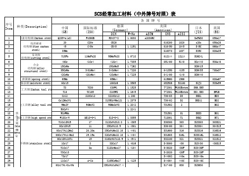
SCS经常加工材料(中外牌号对照)表序号Item种类(Description)各 国 牌 号中国(GB)国际标准(IS0)德国(Germany)美国(American)日本(JIS)英国(BS)DIN W-NrASTM UNSAISI1黑色金属(bla ck metal)碳素结构钢(Carbon steel)Q235-A(A3)Fe360B RSt37-2 1.0038A283GRCSAPH38050A172优质碳素结构钢(fine carbonsteel)20C20e CK20G102001020s20c 050A20345C45e CK45 1.1191G104501045S45C 060A47435Mn G103701037S35C 080A355易切削结构钢(cutting steel)Y15Pb 11MnPb289SMnPb28 1.0718G1214412L14SUM24L 6合金结构钢(alloy structural steel)40Cr 41Cr441Cr4 1.7035G514005140SCr440530A40715CrMo 15CrMo5 1.7262SCM415835CrMo 34CrMo434CrMo4 1.7220G413504135SCM435708A37942CrMo 42CrMo442CrMo4 1.7225G414004140SCM44010弹簧钢(spring steel)65Mn 65Mn4G156601566080A6711轴承钢(axletree steel)GCr15100Cr61.3505G5298652100SUJ2535A9912碳素工具钢(Carbon tool steel)T8TC80C80W1 1.1525T72301W108Extra SK6,SK513T10TC105C105W2 1.1645T72301W110ExtraSK4,SK3BW1B 14合金工具钢(alloy tool steel)Cr12210Cr12X210Cr12 1.208T30403D3SKD1BD315Cr12Mo1V1X155CrVMo121 1.2379T30402D2SKD11BD2169Mn2V 90MnV290MnCrV81.2842T315022BO21750CrV41.2241189CrWMn T31501O1SKS3BO119高速工具钢(high speed steel)W18Cr4V HS18-0-1S18-0-1 1.3355T12001T1SKH2BT120不锈钢(stainless steel)Y1Cr18Ni917X12CrNiS18.8 1.4305S30300303SUS303303S21210Cr18Ni911X5CrNi18.9 1.4301S30400304SUS304304S15220Cr17Ni12Mo220,20a X5CrNiMo18.10 1.4401S31600316SUS316316S162300Cr17Ni14Mo219,19a X2CrNiMo18.10 1.4404S31603316L SUS316L 316S1224OCr18Ni10Ti15X10CrNiTi18.91.4541S32100321SUS321321S12251Cr178X8Cr17 1.4016S43000430SUS430430S1526Y1Cr178aX12CrMos171.4104S4*******F SUS430F 27Y3Cr13S42020420F SUS420F 287Cr17S44002440A SUS440A 2911Cr17A-1b X105CrMo17 1.4125S44004440C SUS440C 300Cr17Ni4Cu4NbX5CrNiCuNb17.4S17400630SUS630meta l)SCS经常加工材料(中外牌号对照)表序号Item 种类(Description)各 国 牌 号中国(GB)国际标准(IS0)德国(Germany)美国(American)日本(JIS)英国(BS)DIN W-Nr ASTM UNS AISI2PTFE polytetrafluoroethylene聚四氟乙烯3POM polyformaldehyde聚甲醛4PA polyamide聚酰胺5ABS acrylonitrile-butadiene-styrene copolymer丙烯腈-丁二烯-苯乙烯共聚物6PC polycarbonate聚碳酸酯7PE polyethylene氯乙烯8PVC poly(vinyl chloride)聚氯乙烯9PSU polysulfone聚砜10PUR polyurethane聚氨酯11酚醛树脂布层fabric phenolic laminated胶木板12环氧玻璃纤维板FR-4epoxy polyesterglass fiber plank环氧玻璃纤维板工程塑料(engineeringplastic)法国(NF)A37-2XC18XC42H1S250Pb42C415CD4.0534CD4100C6Y2105Z200C12Z160CDV12.0390MV890MCW5HS18-0-1Z10CNF18.09 Z6CN18.09 Z6CND17.12 Z2CND17.12 Z6CNT18.11Z8C17Z10CF17Z30CF13Z100CD17Z6CND17.04法国(NF)Z6CN18.09 Z6CND17.12Z6CNT18.10Z8C17Z20C13Z6CNU17.04瑞典(Sweden)H20H20,SH法国(NF)Cu-a1,Cu-a2CuZn40CuZn40CuZn40Pb CuSn4Zn4Pb4CuSn6PCuAl6CuBe2202450525083606160827075法国(NF)UNS ASTM1铜冶炼产品T2(99.90)Cu-ETP E-Cu57C11000C11000C1100C101Cu-a1,Cu-a22加工黄铜H62CuZn40CuZn40C27400C27400C2800CZ109(Cu60)CuZn403H59CuZn40CuZn40C28000C28000(Cu60)C2801CZ109(Cu60)CuZn40 4HPb62-0.8CuZn35Pb1C35000C35000C35015HPb59-1CuZn39Pb1CuZn40Pb2C38000C38000C3710CZ122CuZn40Pb6加工青铜QSn4-4-4CuSn4Pb4Zn3C54400C54400C5441CuSn4Zn4Pb47QSn6.5-0.1CuSn6CuSn6C51900C51900C5191PB103CuSn6P 8QSn6.5-0.4 CuSn6CuSn6C51900C51900C5191PB103CuSn6P 9QAl5CuAl5CuAl5C60600C60600CA101CuAl6 10QBe2CuBe2CuBe2C17200C17200C1720CuBe2 11铸造青铜ZCuSn10Zn2GCuSn10Zn2G-CuSn10Zn C90500C90500BC3G1CuSn12变形铝及铝合金2A11(LY11)AlCuMg1A920172017A20172017122A12(LY12)AlCuMg2A920242024A202420242024135A02(LF2)AlMg2.5A950525052A5052N45052 145A03(LF3)AlMg3A950525052A5052N45052 155083(LF4)5083AlMg4.5Mn A950835083A5083N85083 166A02(LD2)A960616061A6061H20176061(LD30)6061AlMg1SiCu A960616061A6061H206061 186063(LD31)6063AlMgSi0.5A960636063A6063H96063 1960826082AlMgSiMn6082 207A04(LC4)A9707570757075 2170757075AlZnMgCu1.5A970757075A70757075UNS ASTM22铸造及压铸铝合金ZL101Al-Si7Mg G-AlSi7Mg A03560A03560AC4C LM25A-S7G99.9%纯铜,硬度低,加工易变形,易氧化,导电导热性好。

第四节塑料模具钢材的选择模具型腔及零部件包括型腔、型芯、滑块、镶件、斜顶、侧抽等,是与塑料直接接触而成型制品的模具零部件。
模具型腔及零部件的材质直接关系到模具的质量、寿命,决定着所成型塑料制品的外观及内在质量,必须十分慎重,一般要在合同规定及客户要求的基础上,根据制品和模具的要求及特点选用。
一、模具型腔及零部件用模具钢材的选用原则:根据所成型塑料的种类、制品的形状、尺寸精度、制品的外观质量及使用要求、生产批量大小等,兼顾材料的切削、抛光、焊接、蚀纹、变形、耐磨等各项性能,同时考虑经济性以及模具的制造条件和加工方法,以选用不同类型的钢材。
1.1)对于成型透明塑料制品的模具,其型腔和型芯均需选用高镜面抛光性能的高档进口钢材:如718(P20+Ni类)、NAK80(P21类)、STAVAX ESR(420类)、H13类钢等,其中718、NAK80为预硬状态,不需再进行热处理;STAVAX ESR及H13类钢均为退火状态,硬度一般为HB160~200,粗加工后需进行真空淬火及回火处理,STAVAX ESR 的硬度一般为HRC40~50,H13类钢的硬度一般为HRC45~55(可根据具体牌号确定)。
1.2)对于制品外观质量要求高、长寿命、大批量生产的模具,其成型零部件材料选择如下:a)型腔需选用高镜面抛光性能的高档进口钢材:718;P20+Ni;NAK80;P21,均为预硬料,不需再进行热处理。
b)型芯可选用中低档进口P20或P20+Ni类钢材:如618、738、1.2738、638等,均为预硬状态;对生产批量不大的模具,也可选用国产塑料模具钢或S50C、S55C等进口优质碳素钢。
1.3)对于制品外观质量要求一般的模具,其成型零部件材料选择如下:a)小型、精密模具:型腔和型芯均选用中档进口P20或P20+Ni类钢材。
b)大中型模具,所成型塑料对钢材无特殊要求:型腔可选用中低档进口P20或P20+Ni类钢材;型芯可选用低档进口P20类钢材或进口优质碳素钢S50C、S55C等,也可选用国产塑料模具钢。
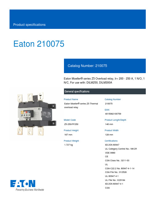
Eaton 210075Eaton Moeller® series Z5 Overload relay, Ir= 200 - 250 A, 1 N/O, 1 N/C, For use with: DILM250, DILM300AGeneral specificationsEaton Moeller® series Z5 Thermal overload relay2100754015082100759Z5-250/FF250146 mm 167 mm 128 mm 1.727 kgIEC/EN 60947UL Category Control No.: NKCR VDE 0660 CECSA Class No.: 3211-03 ULCSA-C22.2 No. 60947-4-1-14 CSA File No.: 012528 UL 60947-4-1 UL File No.: E29184 IEC/EN 60947-4-1 CSAProduct NameCatalog Number EANModel Code Product Length/Depth Product Height Product Width Product Weight CertificationsReset pushbutton manual/autoTrip-free releaseTest/off buttonPhase-failure sensitivity (according to IEC/EN 60947, VDE 0660 Part 102)-25 °C60 °C25 °C40 °CCLASS 10 ADamp heat, constant, to IEC 60068-2-78Damp heat, cyclic, to IEC 60068-2-30IP00Separate mountingDirect mountingDirect attachment/single positioning200 A250 AIII3Overload relay Z5With terminal cover, Protection against direct contact when actuated from front (EN 50274)4000 V (auxiliary and control circuits)8000 V ACFeatures Ambient operating temperature - minAmbient operating temperature - maxAmbient operating temperature (enclosed) - minAmbient operating temperature (enclosed) - maxClassClimatic proofingDegree of protectionMounting methodOverload release current setting - minOverload release current setting - maxOvervoltage categoryPollution degreeProduct categoryProtectionRated impulse withstand voltage (Uimp)Shock resistance10 g, Mechanical, Sinusoidal, Shock duration 10 ms Branch circuits, (UL/CSA)≤ 0.25 %/K, residual error for T > 40° Continuous 25 mm width, Main connection185 mm²2 x (0.75 - 2.5) mm², Control circuit cables1 x (0.75 - 2.5) mm², Control circuit cables1 x (0.75 - 4) mm², Control circuit cables2 x (0.75 - 4) mm², Control circuit cables2/0 - 500 MCM, Main cables2 x (18 - 14), Control circuit cables185 mm²16 mm (Hexagon head spanner SW)8 mmM10 x 35, Terminal screw, Main connectionsM3.5, Terminal screw, Control circuit cables1 x 6 mm, Terminal screw, Control circuit cables, Standard screwdriver2, Terminal screw, Control circuit cables, Pozidriv screwdriver18 Nm, Main cable connection screw/bolt1.2 Nm, Screw terminals, Control circuit cables6 A 1.5 A 1200 A Class L, max. Fuse, SCCR (UL/CSA) 18 kA, SCCR (UL/CSA)1200 A, max. CB, SCCR (UL/CSA)500 A gG/gL, Fuse, Type “1” coordinationSuitable forTemperature compensationTerminal capacity (busbar)Terminal capacity (flexible with cable lug)Terminal capacity (flexible with ferrule)Terminal capacity (solid)Terminal capacity (solid/stranded AWG)Terminal capacity (stranded with cable lug)Width across flatsStripping length (control circuit cable)Screw sizeScrewdriver sizeTightening torqueConventional thermal current ith of auxiliary contacts (1-pole,open)Rated operational current (Ie) at AC-15, 120 VShort-circuit current rating (basic rating)Short-circuit protection rating1.5 A0.9 A0.4 A0.2 A0.9 A0.75 A1000 V440 V, Between auxiliary contacts and main contacts, According to EN 61140240 V AC, Between auxiliary contacts, According to EN 61140 500 V AC, Between main circuits, According to EN 61140R300, DC operated (UL/CSA)B300 at opposite polarity, AC operated (UL/CSA)B600 at opposite polarity, AC operated (UL/CSA)600 VAC600 VAC 500 A gG/gL, Fuse, Type “2” coordinationMax. 6 A gG/gL, fuse, Without welding, Auxiliary and control circuits111143.5 W0 W14.5 W250 A0 WMeets the product standard's requirements.Meets the product standard's requirements.Meets the product standard's requirements.Meets the product standard's requirements.Rated operational current (Ie) at AC-15, 220 V, 230 V, 240 V Rated operational current (Ie) at AC-15, 380 V, 400 V, 415 V Rated operational current (Ie) at DC-13, 110 VRated operational current (Ie) at DC-13, 220 V, 230 V Rated operational current (Ie) at DC-13, 24 VRated operational current (Ie) at DC-13, 60 VRated operational voltage (Ue) - maxSafe isolationSwitching capacity (auxiliary contacts, pilot duty) Voltage rating - maxVoltage rating - max Number of auxiliary contacts (change-over contacts)Number of auxiliary contacts (normally closed contacts) Number of auxiliary contacts (normally open contacts) Number of contacts (normally closed contacts)Number of contacts (normally open contacts)Equipment heat dissipation, current-dependent PvidHeat dissipation capacity PdissHeat dissipation per pole, current-dependent PvidRated operational current for specified heat dissipation (In) Static heat dissipation, non-current-dependent Pvs10.2.2 Corrosion resistance10.2.3.1 Verification of thermal stability of enclosures10.2.3.2 Verification of resistance of insulating materials to normal heat10.2.3.3 Resist. of insul. mat. to abnormal heat/fire by internal elect. effectsMeets the product standard's requirements.Does not apply, since the entire switchgear needs to be evaluated.Does not apply, since the entire switchgear needs to be evaluated.Meets the product standard's requirements.Does not apply, since the entire switchgear needs to be evaluated.Meets the product standard's requirements.Does not apply, since the entire switchgear needs to be evaluated.Does not apply, since the entire switchgear needs to be evaluated.Is the panel builder's responsibility.Is the panel builder's responsibility.Is the panel builder's responsibility.Is the panel builder's responsibility.Is the panel builder's responsibility.The panel builder is responsible for the temperature rise calculation. Eaton will provide heat dissipation data for the devices.Is the panel builder's responsibility. The specifications for the switchgear must be observed.Product Range Catalog Switching and protecting motorseaton-tripping-devices-z5-overload-relay-characteristic-curve-003.eps eaton-tripping-z5-overload-relay-characteristic-curve.epsDA-DC-00004856.pdfDA-DC-00004846.pdfeaton-tripping-devices-overload-relay-z5-overload-relay-dimensions-002.epseaton-tripping-devices-overload-relay-z5-overload-relay-3d-drawing.epsDA-CE-ETN.Z5-250_FF250IL03407006ZIL026005ZUIL03407081ZDA-MN-h1476dgbDA-CS-z5_ff250DA-CD-z5_ff250eaton-general-release-zeb-overload-relay-wiring-diagram.epseaton-tripping-devices-overload-relay-zeb-overload-relay-wiring-diagram.eps10.2.4 Resistance to ultra-violet (UV) radiation10.2.5 Lifting10.2.6 Mechanical impact10.2.7 Inscriptions10.3 Degree of protection of assemblies10.4 Clearances and creepage distances10.5 Protection against electric shock10.6 Incorporation of switching devices and components 10.7 Internal electrical circuits and connections10.8 Connections for external conductors10.9.2 Power-frequency electric strength10.9.3 Impulse withstand voltage10.9.4 Testing of enclosures made of insulating material 10.10 Temperature rise10.11 Short-circuit rating10.12 Electromagnetic compatibility CatalogsCharacteristic curve Declarations of conformity DrawingseCAD modelInstallation instructionsManuals and user guides mCAD modelWiring diagramsEaton Corporation plc Eaton House30 Pembroke Road Dublin 4, Ireland © 2023 Eaton. All Rights Reserved. Eaton is a registered trademark.All other trademarks areproperty of their respectiveowners./socialmediaIs the panel builder's responsibility. The specifications for the switchgear must be observed.The device meets the requirements, provided the information in the instruction leaflet (IL) is observed.10.13 Mechanical function。

800-543-9038 866-805-7089 203-791-8396 •Bubble tight shut-off to ANSI Class 150 Standards • Long stem design allows for 2” insulation minimum• Valve Face-to-face dimensions comply with API 609 & MSS-SP-68•Designed to be installed between ASME/ANSI B16.5 Flanges • Completely assembled and tested, ready for installation •Tees comply with ASME/ANSI B16.1 Class 125 FlangesApplicationThese valves are designed to meet the needs of HVAC and Commercial applications requiring positive shut-off for liquids at higher pressures and temperatures. Typical applications include chiller isolation, cooling tower isolation, change-over systems, large air handler coil control, bypass and process control applications. The large C v values provide for an economical control valve solution for larger fl ow applications.Dead End ServiceUtilizes larger retainer ring set screws to allow the valve to be placed at the end of the line without a down stream fl ange in either fl ow direction while still holding full pressure.MOD ON/OFF ValveSize C v 10°20°30°40°50°60°70°80°90°F750-150SHP 2”102 1.50 6.10142639567799102F765-150SHP 2½”146 2.208.8020375580110142146F780-150SHP 3”228 3.4014325787125171221228F7100-150SHP 4”451 6.802763114171248338437451F7125-150SHP 5”7141143100180271393536693714F7150-150SHP 6”1103176615427841960782710701103F7200-150SHP 8”2064311242895207841135154820022064F7250-150SHP 10”35175321149288613361934263834113517F7300-150SHP 12”483773290677121918382660362846924837F7350-150SHP 14”6857103411960172826063592514366516857F7 Series 3-Way, ANSI Class 150 Butterfl y Valve Reinforced Tefl on Seat, 316 Stainless DiscTechnical Data Servicechilled, hot water, 60% glycol,steam to 50 psi Flow characteristic modifi ed equal percentage, unidirectional Controllable fl ow range 82°Sizes2" to 14"Type of end fi tting for use with ASME/class 125/150 fl anges Materials Body Disc Seat ShaftGland seal Bushingscarbon steel full lug 316 stainless steel RPTFE17-4 PH stainless PTFEglass backed PTFEMedia temperature range -20°F to 400°F [-30°C to 204°C]Body pressure rating ANSI Class 150 Close-off pressure 285 psiRangeability100:1 (for 30 deg to 70 deg range)Maximum velocity 32 FPS Leakagebubble tight3-way Valves Suitable Actuators Valve Nominal SizeTypeNon Fail-SafeElectronic Fail-Safe C v 90°C v 60°Inches ANSI 150 3-way 1501502F750-150SHPG M S e r i e sP R S e r i e sG K S e r i e s 2½F765-150SHP 3F780-150SHP 4F7100-150SHP 5F7125-150SHP S Y S e r i e s (2 Y e a r W a r r a n t y )6F7150-150SHP 8F7200-150SHP 10F7250-150SHP 12F7300-150SHP 14*F7350-150SHP1021462284517141103206435174837685780125248393607113519342660359256866-805-7089 203-791-8396 LATIN AMERICA / CARIBBEANMaximum Dimensions (Inches)F750-150SHP 2”102 4.50 6.38 6.3816.50 4.7545/8-11 UNC GK150Electronic Fail-SafeF765-150SHP 2½”146 5.00 6.88 6.8817.00 5.5045/8-11 UNC150F780-150SHP 3”228 5.507.567.5617.50 6.0045/8-11 UNC 150F750-150SHP 2”102 4.50 6.38 6.3816.50 4.7545/8-11 UNC 2*GK285F765-150SHP 2½”146 5.00 6.88 6.8817.00 5.5045/8-11 UNC 285F780-150SHP 3”228 5.507.567.5617.50 6.0045/8-11 UNC 285F750-150SHP 2”102 4.50 6.38 6.3816.50 4.7545/8-11 UNC GM150Non-Spring Return Electronic Fail-Safe (K)F765-150SHP 2½”146 5.00 6.88 6.8817.00 5.5045/8-11 UNC 150F780-150SHP 3”228 5.507.567.5617.50 6.0045/8-11 UNC 150F7100-150SHP 4”451 6.508.638.6318.007.5085/8-11 UNC 150F750-150SHP 2”102 4.50 6.38 6.3816.50 4.7545/8-11 UNC 2*GM285F765-150SHP 2½”146 5.00 6.88 6.8817.00 5.5045/8-11 UNC 285F780-150SHP 3”228 5.507.567.5617.50 6.0045/8-11 UNC 285F750-150SHP 2”102 4.50 6.38 6.3814.00 4.7545/8-11 UNC PR/PK285F765-150SHP 2½”146 5.00 6.88 6.8814.50 5.5045/8-11 UNC 285F780-150SHP 3”228 5.507.567.5615.00 6.0045/8-11 UNC 285F7100-150SHP 4”451 6.508.638.6316.007.5085/8-11 UNC 285F7125-150SHP 5”7147.509.759.7524.258.5083/4-10 UNC SY4…285F7150-150SHP 6”11038.0010.2510.2524.759.5083/4-10 UNC 285F7200-150SHP 8”20649.0011.5011.5032.0011.7583/4-10 UNC SY4…150F7250-150SHP 10”351711.0013.8113.8133.0014.25127/8-9 UNC SY4…150SY5…285F7300-150SHP 12”483712.0015.8115.8135.0017.00127/8-9 UNC SY5…150SY7…285F7350-150SHP14”685714.0017.6217.6236.0018.75121-8 UNCSY7…285F7 Series 3-Way, ANSI Class 150 Butterfl y ValveReinforced Tefl on Seat, 316 Stainless DiscDimensions “A, B and C” do not include fl ange gaskets. (3 required per valve)Application Notes1. Valves are rated at 285 psi differential pressure in the closed position @ 100°F media temperature.2.Valves are furnished with lugs tapped for use between ANSI Class 125/150 fl anges conforming to ANSI B16.5 Standards.3.3-way assemblies are furnished assembled with Tee, calibrated and tested,ready for installation. All 3-way assemblies require the customer to specify the 3-way confi guration code prior to order entry to guarantee correct place-ment of valves and actuator(s) on the assembly.4. Dimension “D” allows for actuator(s) removal without the need to remove the valve from the pipe.5. Weather shields are available, dimensional data furnished upon request.6. Dual actuated valves have single actuators mounted on each valve shaft.7.Flange gaskets (3 required, not provided with valve) MUST be used between valve and ANSI fl ange.8. F lange bolts are not included with the valve. These are furnished by others.SHP seriesvalves have a preferred flow direction.P r e f e r r e d F l o w r a t e0DCABB,CDAGKX24-MFT-X1 Modulating, Electronic Fail-Safe, 24 V, for DC2...10 V or 4...20 mA Control SignalTechnical dataElectrical data Nominal voltage AC/DC 24 VNominal voltage frequency50/60 HzPower consumption in operation12 WPower consumption in rest position 3 WTransformer sizing21 VA (class 2 power source)Electrical Connection18 GA plenum cable with 1/2" conduitconnector, degree of protection NEMA 2 / IP54,3 ft [1 m] 10 ft [3 m] and 16ft [5 m]Overload Protection electronic throughout 0...95° rotationFunctional data Options positioning signal variable (VDC, on/off, floating point)Position feedback U variable VDC variableBridging time programmable 0...10 s (2 s default) delaybefore fail-safe activatesPre-charging time 5...20 sDirection of motion motor selectable with switch 0/1Direction of motion fail-safe reversible with switchManual override external push buttonAngle of rotation Max. 95°, adjustable with mechanical stopAngle of rotation note adjustable with mechanical stopRunning Time (Motor)default 150 s, variable 95...150 sRunning time motor variable95...150 sRunning time fail-safe<35 sNoise level, motor52 dB(A)Noise level, fail-safe61 dB(A)Position indication Mechanically, 30...65 mm strokeSafety data Degree of protection IEC/EN IP54Degree of protection NEMA/UL NEMA 2Enclosure UL Enclosure Type 2Agency Listing cULus acc. to UL60730-1A/-2-14, CAN/CSAE60730-1:02, CE acc. to 2014/30/EU and2014/35/EU; Listed to UL 2043 - suitable for usein air plenums per Section 300.22(c) of the NECand Section 602.2 of the IMCQuality Standard ISO 9001Ambient temperature-22...122°F [-30...50°C]Storage temperature-40...176°F [-40...80°C]Ambient humidity Max. 95% RH, non-condensingmaintenance-freeGKX24-MFT-X1Mode of operationProduct featuresSY9~12 Replacement HandwheelAccessoriesElectrical accessoriesDescriptionType Feedback potentiometer 10 kΩ add-on, grey P10000A GR Feedback potentiometer 1 kΩ add-on, grey P1000A GR Feedback potentiometer 140 Ω add-on, grey P140A GR Feedback potentiometer 2.8 kΩ add-on, grey P2800A GR Feedback potentiometer 5 kΩ add-on, grey P5000A GR Feedback potentiometer 500 Ω add-on, grey P500A GR Auxiliary switch 1 x SPDT add-on S1A Auxiliary switch 2 x SPDT add-onS2A Service Tool, with ZIP-USB function, for programmable andcommunicative Belimo actuators, VAV controller and HVAC performance devicesZTH USElectrical installationINSTALLATION NOTESActuators with appliance cables are numbered.Provide overload protection and disconnect as required.Actuators may also be powered by DC 24 V.Only connect common to negative (-) leg of control circuits.A 500 Ω resistor (ZG-R01) converts the 4...20 mA control signal to 2...10 V.Control signal may be pulsed from either the Hot (Source) or Common (Sink) 24 V line.For triac sink the Common connection from the actuator must be connected to the Hotconnection of the controller. Position feedback cannot be used with a triac sink controller; theactuator internal common reference is not compatible.IN4004 or IN4007 diode. (IN4007 supplied, Belimo part number 40155).Actuators may be controlled in parallel. Current draw and input impedance must be observed.Master-Slave wiring required for piggy-back applications. Feedback from Master to controlinput(s) of Slave(s).Meets cULus requirements without the need of an electrical ground connection.Warning! Live electrical components!During installation, testing, servicing and troubleshooting of this product, it may be necessary to work with live electrical components. Have a qualified licensed electrician or other individual who has been properly trained in handling live electrical components perform these tasks. Failure to follow all electrical safety precautions when exposed to live electrical components could result in death or serious injury.Wiring diagrams On/OffFloating PointGKX24-MFT-X1 VDC/mA Control PWM Control。

.压力容器用钢焊材一览表种类牌号中国 GB美国 AWS 碳THJ422E4303—钢THJ426E4316E6016焊THJ427E4315E6015条THJ506E5016E7016THJ507E5015E7015THJ506R E5016-G E7016-GTHJ507RH E5015-G E7015-GTHJ557R E5MoV-15—低THJ606E6016-D1E9016-D1合金THJ607E6015-D1E9015-D1钢THW707Ni E5515-C1—焊THR207E5515-B1E8015-B1条THR307E5515-B2E8015-B2THR317E5515-B2-V—THR407E6015-B3—THR507E5MoV-15—种类不锈钢焊条气保护实芯焊丝牌号中国 GB美国 AWSTHA002E308L-16E308L-16THA022E316L-16E316L-16THA102E308-16E308-16THA107E308-15E308-15THA132E347-16E347-16THA137E347-15E347-15THA202E316-16E316-16THA207E316-15E316-15THA212E318-16E318-16THA242E317-16E317-16THA302E309-16E309-16THA307E309-15E309-15THG202E410-16E410-16———THQ-G2Si EN440 G38 4MG2SiTHQ-50CG4EN440 G38 3CG4Si1型号牌号GBTHT49-1ER49-1THT-10MnSi ER50-GTHT50-6ER50-6( TIG-J50 )THT55-B2ER55-B2THT55-B2V ER55-GTHT-307H09Cr21Ni9Mn4Mo THS-307THT-307SiH10Cr21Ni10Mn6Si1 THS-307SiTHT-308H08Cr21Ni10Si THS-308THT-308LH03Cr21Ni10Si THS-308LTHT-308LSiH03Cr21Ni10Si1 THS-308LSiTHT-309H12Cr24Ni13Si THS-309THT-309MoH12Cr24Ni13Mo2 THS-309MoTHT-309LH03Cr24Ni13Si THS-309L类型碳钢焊丝珠光体耐热钢焊丝不锈钢焊丝.氩弧焊焊丝主要用途用于船舶、石化、核电话等高压管的对接及角焊用于薄板及打底焊接构造用于管道、平板等需作抛光度正确时的焊接用于工作温度550℃以下的锅炉受热面管子蒸汽管道,高压容器,石油精练设施构造的焊接用于工作温度550℃以下的锅炉受热面管子蒸汽管道,高压容器,石油精练设施构造的焊接用于防弹钢、覆面不锈钢及碳钢异材的焊接用于高锰钢、硬化性耐磨钢及非磁性钢的焊接用于 308、 301、304 等不锈钢构造的焊接用于 304L 、 308L 等不锈钢构造的焊接用于改良填补金属的工艺性、焊接操作性及流动性用于异种钢的焊接,如碳钢、低合金钢与不锈钢的焊接用于 Cr22Ni12Mo2复合钢以及异种钢的焊接用于 309S、 1Cr13、 1Cr17、低碳不锈钢、低碳覆面钢以及异种钢的焊接. THT-309LSi用于 309 型不锈钢以及 304 型不锈钢与碳钢的焊接H03Cr24Ni13Si1THS-309LSiTHT-309LMo用于异种钢的焊接或韧性较差的马氏体、铁素体不锈钢的焊接H03Cr24Ni13Mo2THS-309LMoTHT-310用于高温条件下工作的耐热钢以及1Cr5Mo 、 1Cr13 等不可以进行预热及后热办理的焊接H12Cr26Ni21SiTHS-310THT-312用于异种母材不锈钢覆面、硬化性低合金钢以及焊接困难或易发生气孔状况的焊接H15Cr30Ni9THS-312THT-316用于磷酸、亚硫酸、醋酸及盐类腐化介质构造的焊接H08Cr19Ni12Mo2SiTHS-316THT-316L用于尿素、合成纤维等构造及不可以进行热办理的铬不锈钢及复合钢的焊接H03Cr19Ni12Mo2SiTHS-316LTHT-316LSi用于同样种类不锈钢以及复合钢构造的焊接H03Cr19Ni12Mo2Si1THS-316LSiTHT-317用于重要的耐腐化化工容器的焊接H08Cr19Ni14Mo3THS-317THT-317L用于重要的耐腐化化工容器的焊接H03Cr19Ni14Mo3THS-317LTHT-321用于 304、 321、347 型不锈钢以及耐热钢的焊接H08Cr19Ni10TiTHS-321THT-347用于 304、 321、347 型不锈钢以及耐热钢的焊接H08Cr20Ni10NbTHS-347THT-410用于 410、 420 型不锈钢以及耐蚀耐磨表面的堆焊H12Cr13THS-410THT-420用于 Cr13 马氏体不锈钢耐腐化性资料的堆焊H31Cr13THS-420THT-430用于腐化(硝酸)、耐热同种类不锈钢表面堆焊H10Cr17THS-430THT-2209用于含 Cr22% 双相不绣钢的焊接H03Cr22Ni8Mo3NTHS-2209.碳钢焊条型号牌号GBJ421E4313 THJ421X E4313 THJ421Fe18E4324 THJ422E4303 THJ422GM E4303THJ423E4301E4310 THJ425XE4311熔敷金属化学成分( %)(≤)熔敷金属力学性能(≥)C MnSi S PRel/RP0.2Rm A AKV其余MPa MPa%J0.100.32/0.0300.035355440/220℃—0.300.55570470.100.32/0.0350.040330420170℃—0.300.55270.120.30/0.0350.040330420170℃—0.350.60470.100.32/0.0350.040330420220℃—0.250.55270.100.32/0.0350.040330420220℃—0.250.55270.100.32/0.0350.04033042022-20℃—0.300.55270.200.32/0.0350.04033042022-30℃—0.300.6027特色与用途焊接低碳钢构造,特别合用于薄板小件及短焊缝的中断焊和盖面焊。

AMDTH-□/C02□ 系列电动机保护器使用说明产品概述主要特点:DSP 为核心,数字设定,数字显示,保护功能完备、保护性能可靠。
保护功能:缺相、短路、接地、堵转、过载、电流不平衡、欠载。
适用范围:额定电压不高于1140V,50Hz或60Hz,起动负载重、起动时间长的三相交流电动机。
电动机保护器型号 AMDTH-2 AMDTH-5AMDTH-10AMDTH-20AMDTH-50AMDTH-100 AMDTH-150 AMDTH-200最大设定电流(A) 2.3 5.5 11 23 55 110 165 220 最小设定电流(A) 0.4 1 2 4 10 20 30 40电动机最大功率(KW) 1.1 2.2 4 11 22 45 75 110 电动机最小功率(KW) 0.22 0.55 1.1 2.2 5.5 11 18.5 22电动机电源穿线孔Φ(mm)20 20 20 20 20 20 30 30 连接电缆:连接主单元与电流检测单元,6×0.3mm²×2.2 m双绞屏蔽电缆工作电压:AC 85V — 265V、DC 85V — 265V功率消耗:小于 2W采集精度:0.5环境温度:- 20℃ — 50℃继电器触点:AMDTH-□/C021:1常开、常闭触点,AC 250V/10A(阻性负载)、DC 30V/10A AMDTH-□/C023:独立2常开触点,AC 220V/5A(阻性负载)、DC 30V/5AAMDTH-□/C024:独立1常开、1常闭触点,AC 220V/5A(阻性负载)、DC 30V/5A AMDTH-□/C02□系列电动机保护器数据显示AMDTH-□/C02□ 系列电动机保护器在电动机正常运行时,显示电动机A、B、C相电流;当电动机发生缺相、短路、接地、堵转、过载、电流不平衡、欠载故障时,断开内部继电器触点停止电动机运行(故障灯亮),同时显示故障代码指示故障类型,并且显示电动机发生故障时的A、B、C相电流值。
