翻译译文:
大尺寸塑料模具钢AISI.P20钢的淬火过程设计
大尺寸的AISI.P20钢,用于厚度不小于200mm的塑料模具钢,为获得一定的淬硬层,适当的热处理过程是十分关键的。本文就AISI.P20钢的不同热处理过程如油淬,直接水淬,水淬前预冷和自我回火,做了计算机模拟的数字调研,对数学模型热处理过程细节做了讨论,包括局部热传递的不同反应式,热物理性质,潜热,热传递系数和相变计算,结果显示;预冷水淬和自我回火,不仅能有效地防止淬裂,而且比油淬获得更深的淬硬层
关键词:计算机模拟,热处理过程,AISI.P20钢,塑料模具
1.前言
AISI.P20钢,塑料模具钢,通常淬硬前硬度值大约30~36HRC。P20钢应该有均匀的硬度,在同一截面上,硬度值最大不超过3HRC,这就要求共析铁素体尽可能少。AISI.P20钢:0.28%~0.40%C,0.20%~0.80%Si,0.60%~1.00%Mn,1.40~2.0%Cr,0.30%~0.553%Mo,<0. 03%S,<0.03%P。油淬时钢的最大厚度不应超过150mm。厚度超过150mm的大尺寸的钢,为获得一定的淬硬层,适当的热处理过程是非常关键的。然而热处理过程是包括热传递现象,冶金性,力学现象等复杂的过程。它很难或者说不可能用分析的方法来正确而有效地描述所有的物理现象。所以,在过去,热处理过程的建立只是根据经验,而缺乏科学依据。近年来,计算机模拟使其有了巨大的进步。进行温度与相度应力的耦合。3D非线性有限元素分析,相变动力的计算。对急剧转变边界条件的处理等。这些计算结果为引导制造业的计算机模拟,提供了一些基本法则。本文中,分析由计算机模拟的AISI.P20钢的不同热处理过程,提出预冷水淬和自我回火
2.热处理过程的数学模型
2.1热传递过程中,局部不同的反应:
大尺寸钢在热处理过程中的导热量,可以通过3D模型局部不同反应方程计算出来注:7
注: 8
t
T pc q z T z y T y x T ??=+????+????+????ρλλλχ)()()( (1) 边界条件和初始条件为:
00()(,,)s t T h T T n
T T x y z αλ=?-=-?=(2)(3)
λ是导热性,ρC 是比热容,q 是内热源
n T ??是垂直于表面的温度梯度,s T 是表面温度,αT 是淬火介质温度, n 是传热系数。边界条件与初始条件作为钢的表面温度的函数输入。
在分析瞬时温度时,3D 有限元分析法解传热方程用前一个反应式,当时间范围是离散的,应用后向差分格式。
[][]{}[]{}{}11(4)t t t K C T C T F t t -???+=+ ?????
这里的[]K 代表模具导热率,[]C 代表模具热容率,{}F 是供热介质。 热物理性质:
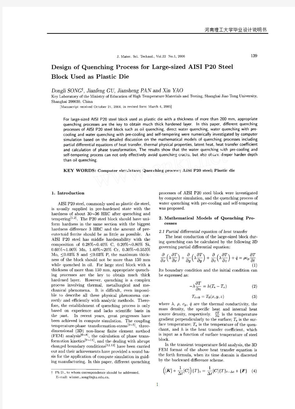
图1 在AISI P20钢上不同微观组织的热物理性质:(a )导热率(b )比热(c )密度(M=马氏体,B=贝氏体,P=珠光体,F=铁素体,A=奥氏体)
上述图1显示:热物理性质是相成分和温度的函数,可表示为
(),()k k k T T ψξξψ=∑ (5)
这里的ψ代表,,p c λρ或,k ξ是第k 相的体积分数,k 分别表示为A (奥氏体),M (马氏体),B (贝氏体),P (珠光体),F (共析铁素体)
注: 9
潜热
由相变产生的内热源的密度由(6)计算
k k d q H dt
ξ=? (6) 这里的k H ?是当奥氏体转变的时候,每单位奥氏体与每单位第k 相的焓差。如表-1所示。k d ξ是第k 相在dt 中的体积分数。
热传递系数
当在空气中冷却时,综合的热传递系数包括:辐射传递系数()r h 和对流转移系数()c h ,即
air r c h h h =+ (7)
辐射传递系数()r h ,表示为:
()()22r s a s a h T T T T εσ=++ (8)
这里ε是表面热辐射系数,本文中取为0.6,σ是Stefan-Boitzmann 常数,σ=5.768)/(10428k m w -?
在空气中冷却的对流转移系数的经验公式可近似地表述为
c h = (9)
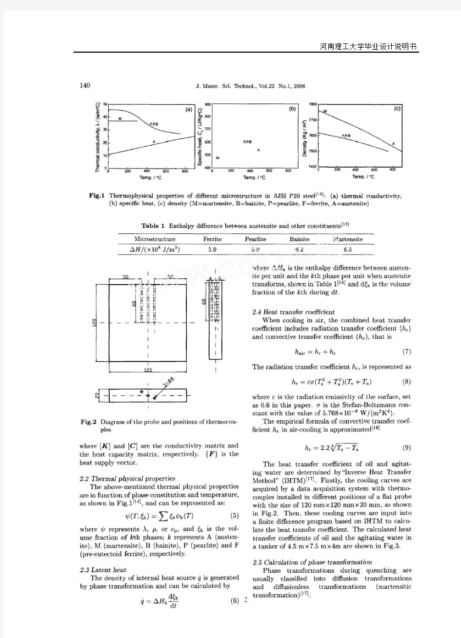
油和搅动的水的热传递曲线是反向热传递方法取得(IHTM)。首先,从数据采集系统取得冷却曲线;这个数据采集系统在不同位置有平探头,尺寸120mm ?120mm ?20mm ,如图2所示。然后,这些冷却曲线输入基于ZHTM 的有限差系统。从而计算出热传递系数。图3所示是计算之中和搅动的水的热传递系数。用的槽车,尺寸为4.5m ?7.5m ?4m 。
注:
10
2.5相变计算
在热处理中的相变通常分为扩散型相变和元扩散型相变(马氏体转变) 对扩散型相变,持续的冷却曲线可能被打断,在极短的时间间隔的恒温区。孕育期采用的是Scheil 可加性法则来确定,也就是标志相转变开始时间John-Mchl-Avraml 公式用来确定潜伏时间和评定微观组织的体积分数
Scheil 可加性法则:
1()i i
t T τ?=∑ (10)
John-Mehl_Avarami 反应式:
注: 11
1exp()n f bt =-- (11)
潜伏时间:
()11*ln 1i
n i i i f t b --??=-????
(12) 潜伏期体积分数: **1exp(())n i i i f b t t =--+? (13)
真正的体积分数:
*11max ()i ri i f f f f f --=+ (14)
这里)(T i τ表示在一定T 下的潜伏期,i t ?表示在一定温度下短暂的等温时间。b 和n 是两个常数,它们由TTT 图上是新相体积分数从1%和99%的两条不同曲线得到。1-ri f 和i f 是新相在 i-1和i 中的体积分数,1-ri f 是奥氏体在i 时间的体积分数max f 新相转变开始的残余奥氏体的体积分数
对马氏体转变,马氏体的数量仅仅是温度的函数,其体积分数由Koistinen-Mar.burger 法则得出:
1exp(())s f M T α=-- (15)
这里s M 是马氏体转变开始温度。α是一个常数,对于AISI.P20钢。0.023α=
3. 结果与讨论
商用FE 软件,MSC.Marc 和用户定义的子程序用于分析AISI.P20钢热处理过程,大尺寸的P20钢1700mm ?1000mm ?460mm.由于对称性,由一个高度的几何条件需要考虑,通过试探法来确定网孔的尺寸,图5所示用膨胀计测试的AISI.20钢的TTT 图。用膨胀计为了便于热处理过程中相转变的计算。
注:
12
3.1油淬
油通常作为AISI.P20钢的淬火介质,来避免在热处理过程中的淬裂额,图3所示油的热传递系数,在860C 奥氏体后。然后大尺寸的钢被油淬,图6所示为油淬后沿中心轴的计算的微观组织分布状态
如图6示,没有发现马氏体,贝氏体也很薄,从钢表面大约10mm ,深处珠光体开始出现。当铁素体体积分数达到峰值12.5%时,从表面大约50mm 深至中心的主要相是珠光体,因此,对大尺寸的P20钢,油淬是不合适的。
3.2 直接水淬
因为油淬的淬硬层太薄,所以搅动的水淬来代替油,在860C ,奥氏体化后,钢被水淬至室温,图7所示是大尺寸的模具钢淬火后沿中心线计算的微观组织分布状态。
从图3(b)中可以看出搅动的水具有很高的冷却能力,当铁素体出现在钢表面100mm深时,珠光体出现在表面下30mm深处。在中心铁素体体积分数增加不足10%,所以,对于想获得更合适的微观组织的大尺寸钢,水淬是合适的虽然,通过直接水淬,能够获得较好的组织分布。但是,在实际热处理中,淬火裂纹总是发生。裂纹通常发生在钢的角落。所以,对于更合适的热处理过程,需要进一步的研究。
3.3 水淬+空气预冷
从图8中可以看出,在直接水淬过程中的裂纹和角落周围的马氏体转变相关。为了克服这个问题,本文中,将设计和模拟新的热处理过程—水淬+空气预冷。
图9所示是空气预冷1200S后的珠光体分布状态。从图9(a)中可以看出,预前空冷合适的时间,角落的奥氏体转变为珠光体,最终降低了在后续的水淬过程中产生裂纹的倾向。图9 b,e,d所示在空气预冷过程中非常薄的珠光体层在角落周围,在钢的大部分区域,奥氏体没有分解,在后续的水淬过程中将持续分解,和直接水淬一样。
注:13
注: 14
在大尺寸P20钢的实际热处理过程中,证明,空气预冷能有效地避免淬硬裂纹,但是,一些小的裂纹仍然产生。这些裂纹位于表面附近。它们是在水淬过程中马氏体转变时产生的。为了使大尺寸AISIP20钢的热处理过程最佳化。本文将设计和模拟另一个热处理过程:空气预冷+水淬+自我回火。
3.4 空气预冷的水淬
图11所示是沿中心线的不同位置的冷却曲线。热处理过程包括4个阶段:预冷1118s ;第一次水淬3892s ;第一次空冷201s ;第二次水淬2380s
图11所示为模拟结果。第一次水淬后,表面温度接近100C ?,低于s M 点,所以,马氏体开始转变。如果继续在水中冷却,钢很容易产生淬火裂纹。此时,钢从水中驱除进入第一次空冷,从中心的热传递将增加表面温度在200C ?以上。因此,转变的马氏体被回火,它的脆性降低,但是短暂的回火不会影响中心的冷却速率。第二次水淬后表面温度低于100c ?中心温度降低接近300C ?。所以,钢被取出后,放在空气里,新的转变的马氏体和表面附近的贝氏体,类似于自我回火,这种方法有效于避免淬硬裂纹。用这个方法形成的组织状态和直接水淬的形成组织状态基本相同。
结论:
根据热传递和微观组织状态的数学模型,大尺寸的塑料模具钢的热处理过程进一步研究。阐述了水能够取代油,作为淬火介质。空气预冷的水淬加自我回火是理想淬火过程之一。
17001000460m m m m m m ??AISI P20钢奥氏体化后第一次空冷直至角落
周围只有薄薄的一层珠光体,而这些角落是最容易产生淬火裂纹的地方。在后续的水淬过程中当表面转变为马氏体时,钢从水中转至空气中,即新形式的马氏体自我回火。模拟结果清楚的显示了预冷和自我回火不会降低淬硬深度。其微观组织状态与直接水淬得到的组织相似,但是后者更能有效阻止淬火裂纹,比油淬能获得更深的淬硬层。
致谢:
此设计项目是由中国科技部支持(NO.MT1:17)作者诚挚的感谢曾经帮助过
的老师和同学,
注:15
外文出处: 《Exploiting Software How to Break Code》By Greg Hoglund, Gary McGraw Publisher : Addison Wesley Pub Date : February 17, 2004 ISBN : 0-201-78695-8 译文标题: JDBC接口技术 译文: JDBC是一种可用于执行SQL语句的JavaAPI(ApplicationProgrammingInterface应用程序设计接口)。它由一些Java语言编写的类和界面组成。JDBC为数据库应用开发人员、数据库前台工具开发人员提供了一种标准的应用程序设计接口,使开发人员可以用纯Java语言编写完整的数据库应用程序。 一、ODBC到JDBC的发展历程 说到JDBC,很容易让人联想到另一个十分熟悉的字眼“ODBC”。它们之间有没有联系呢?如果有,那么它们之间又是怎样的关系呢? ODBC是OpenDatabaseConnectivity的英文简写。它是一种用来在相关或不相关的数据库管理系统(DBMS)中存取数据的,用C语言实现的,标准应用程序数据接口。通过ODBCAPI,应用程序可以存取保存在多种不同数据库管理系统(DBMS)中的数据,而不论每个DBMS使用了何种数据存储格式和编程接口。 1.ODBC的结构模型 ODBC的结构包括四个主要部分:应用程序接口、驱动器管理器、数据库驱动器和数据源。应用程序接口:屏蔽不同的ODBC数据库驱动器之间函数调用的差别,为用户提供统一的SQL编程接口。 驱动器管理器:为应用程序装载数据库驱动器。 数据库驱动器:实现ODBC的函数调用,提供对特定数据源的SQL请求。如果需要,数据库驱动器将修改应用程序的请求,使得请求符合相关的DBMS所支持的文法。 数据源:由用户想要存取的数据以及与它相关的操作系统、DBMS和用于访问DBMS的网络平台组成。 虽然ODBC驱动器管理器的主要目的是加载数据库驱动器,以便ODBC函数调用,但是数据库驱动器本身也执行ODBC函数调用,并与数据库相互配合。因此当应用系统发出调用与数据源进行连接时,数据库驱动器能管理通信协议。当建立起与数据源的连接时,数据库驱动器便能处理应用系统向DBMS发出的请求,对分析或发自数据源的设计进行必要的翻译,并将结果返回给应用系统。 2.JDBC的诞生 自从Java语言于1995年5月正式公布以来,Java风靡全球。出现大量的用java语言编写的程序,其中也包括数据库应用程序。由于没有一个Java语言的API,编程人员不得不在Java程序中加入C语言的ODBC函数调用。这就使很多Java的优秀特性无法充分发挥,比如平台无关性、面向对象特性等。随着越来越多的编程人员对Java语言的日益喜爱,越来越多的公司在Java程序开发上投入的精力日益增加,对java语言接口的访问数据库的API 的要求越来越强烈。也由于ODBC的有其不足之处,比如它并不容易使用,没有面向对象的特性等等,SUN公司决定开发一Java语言为接口的数据库应用程序开发接口。在JDK1.x 版本中,JDBC只是一个可选部件,到了JDK1.1公布时,SQL类包(也就是JDBCAPI)
Injection Molding The basic concept of injection molding revolves around the ability of a thermoplastic material to be softened by heat and to harden when cooled .In most operations ,granular material (the plastic resin) is fed into one end of the cylinder (usually through a feeding device known as a hopper ),heated, and softened(plasticized or plasticized),forced out the other end of the cylinder, while it is still in the form of a melt, through a nozzle into a relatively cool mold held closed under pressure.Here,the melt cools and hardens until fully set-up. The mold is then opened, the piece ejected, and the sequence repeated. Thus, the significant elements of an injection molding machine become: 1) the way in which the melt is plasticized (softened) and forced into the mold (called the injection unit); 2) the system for opening the mold and closing it under pressure (called the clamping unit);3) the type of mold used;4) the machine controls. The part of an injection-molding machine, which converts a plastic material from a sold phase to homogeneous seni-liguid phase by raising its temperature .This unit maintains the material at a present temperature and force it through the injection unit nozzle into a mold .The plunger is a combination of the injection and plasticizing device in which a heating chamber is mounted between the plunger and mold. This chamber heats the plastic material by conduction .The plunger, on each stroke; pushes unbelted plastic material into the chamber, which in turn forces plastic melt at the front of the chamber out through the nozzle The part of an injection molding machine in which the mold is mounted, and which provides the motion and force to open and close the mold and to hold the mold close with force during injection .This unit can also provide other features necessary for the effective functioning of the molding operation .Moving
附录 科技译文: Numerical Control Numerical Control(NC) is a method of controlling the movements of machineComponents by directly inserting coded instructions in the form of numerical data(numbers and data ) into the system.The system automatically interprets these data and converts to output signals. These signals ,in turn control various machine components ,such as turning spindles on and off ,changing tools,moving the work piece or the tools along specific paths,and turning cutting fluits on and off. In order to appreciate the importer of numerical control of machines ,let’s briefly review how a process such as machining has been carried out traditionally .After studying the working drawing of a part, the operator sets up the appropriate process parameters(such as cutting speed ,feed,depth of cut,cutting fluid ,and so on),determines the sequence of operations to be performed,clamps the work piece in a workholding device such as chuck or collet ,and proceeds to make the part .Depending on part shape and the dimensional accuracy specified ,this approach usually requires skilled
附录一英文科技文献翻译 英文原文: Experimental investigation of laser surface textured parallel thrust bearings Performance enhancements by laser surface texturing (LST) of parallel-thrust bearings is experimentally investigated. Test results are compared with a theoretical model and good correlation is found over the relevant operating conditions. A compari- son of the performance of unidirectional and bi-directional partial-LST bearings with that of a baseline, untextured bearing is presented showing the bene?ts of LST in terms of increased clearance and reduced friction. KEY WORDS: ?uid ?lm bearings, slider bearings, surface texturing 1. Introduction The classical theory of hydrodynamic lubrication yields linear (Couette) velocity distribution with zero pressure gradients between smooth parallel surfaces under steady-state sliding. This results in an unstable hydrodynamic ?lm that would collapse under any external force acting normal to the surfaces. However, experience shows that stable lubricating ?lms can develop between parallel sliding surfaces, generally because of some mechanism that relaxes one or more of the assumptions of the classical theory. A stable ?uid ?lm with su?cient load-carrying capacity in parallel sliding surfaces can be obtained, for example, with macro or micro surface structure of di?erent types. These include waviness [1] and protruding microasperities [2–4]. A good literature review on the subject can be found in Ref. [5]. More recently, laser surface texturing (LST) [6–8], as well as inlet roughening by longitudinal or transverse grooves [9] were suggested to provide load capacity in parallel sliding. The inlet roughness concept of Tonder [9] is based on ??e?ective clearance‘‘ reduction in the sliding direction and in this respect it is identical to the par- tial-LST concept described in ref. [10] for generating hydrostatic e?ect in high-pressure mechanical seals. Very recently Wang et al. [11] demonstrated experimentally a doubling of the load-carrying capacity for the surface- texture design by reactive ion etching of SiC
毕业设计(论文)外文文献翻译 文献、资料中文题目:软件开发概念和设计方法文献、资料英文题目: 文献、资料来源: 文献、资料发表(出版)日期: 院(部): 专业: 班级: 姓名: 学号: 指导教师: 翻译日期: 2017.02.14
外文资料原文 Software Development Concepts and Design Methodologies During the 1960s, ma inframes and higher level programming languages were applied to man y problems including human resource s yste ms,reservation s yste ms, and manufacturing s yste ms. Computers and software were seen as the cure all for man y bu siness issues were some times applied blindly. S yste ms sometimes failed to solve the problem for which the y were designed for man y reasons including: ?Inability to sufficiently understand complex problems ?Not sufficiently taking into account end-u ser needs, the organizational environ ment, and performance tradeoffs ?Inability to accurately estimate development time and operational costs ?Lack of framework for consistent and regular customer communications At this time, the concept of structured programming, top-down design, stepwise refinement,and modularity e merged. Structured programming is still the most dominant approach to software engineering and is still evo lving. These failures led to the concept of "software engineering" based upon the idea that an engineering-like discipl ine could be applied to software design and develop ment. Software design is a process where the software designer applies techniques and principles to produce a conceptual model that de scribes and defines a solution to a problem. In the beginning, this des ign process has not been well structured and the model does not alwa ys accurately represent the problem of software development. However,design methodologies have been evolving to accommo date changes in technolog y coupled with our increased understanding of development processes. Whereas early desig n methods addressed specific aspects of the
(此文档为word格式,下载后您可任意编辑修改!) 冷冲模具使用寿命的影响及对策 冲压模具概述 冲压模具--在冷冲压加工中,将材料(金属或非金属)加工成零件(或半成品)的一种特殊工艺装备,称为冷冲压模具(俗称冷冲模)。冲压--是在室温下,利用安装在压力机上的模具对材料施加压力,使其产生分离或塑性变形,从而获得所需零件的一种压力加工方法。 冲压模具的形式很多,一般可按以下几个主要特征分类: 1?根据工艺性质分类 (1)冲裁模沿封闭或敞开的轮廓线使材料产生分离的模具。如落料模、冲孔模、切断模、切口模、切边模、剖切模等。 (2)弯曲模使板料毛坯或其他坯料沿着直线(弯曲线)产生弯曲变形,从而获得一定角度和形状的工件的模具。 (3)拉深模是把板料毛坯制成开口空心件,或使空心件进一步改变形状和尺寸的模具。 (4)成形模是将毛坯或半成品工件按图凸、凹模的形状直接复制成形,而材料本身仅产生局部塑性变形的模具。如胀形模、缩口模、扩口模、起伏成形模、翻边模、整形模等。2?根据工序组合程度分类 (1)单工序模在压力机的一次行程中,只完成一道冲压工序的模具。 (2)复合模只有一个工位,在压力机的一次行程中,在同一工位上同时完成两道或两道以上冲压工序的模具。 (3)级进模(也称连续模) 在毛坯的送进方向上,具有两个或更多的工位,在压力机的一次行程中,在不同的工位上逐次完成两道或两道以上冲压工序的模具。 冲冷冲模全称为冷冲压模具。 冷冲压模具是一种应用于模具行业冷冲压模具及其配件所需高性能结构陶瓷材料的制备方法,高性能陶瓷模具及其配件材料由氧化锆、氧化钇粉中加铝、错元素构成,制备工艺是将氧化锆溶液、氧化钇溶液、氧化错溶液、氧化铝溶液按一定比例混合配成母液,滴入碳酸氢铵,采用共沉淀方法合成模具及其配件陶瓷材料所需的原材料,反应生成的沉淀经滤水、干燥,煅烧得到高性能陶瓷模具及其配件材料超微粉,再经过成型、烧结、精加工,便得到高性能陶瓷模具及其配件材料。本发明的优点是本发明制成的冷冲压模具及其配件使用寿命长,在冲压过程中未出现模具及其配件与冲压件产生粘结现象,冲压件表面光滑、无毛刺,完全可以替代传统高速钢、钨钢材料。 冷冲模具主要零件冷冲模具是冲压加工的主要工艺装备,冲压制件就是靠上、下模具的相对运动来完成的。 加工时由于上、下模具之间不断地分合,如果操作工人的手指不断进入或停留在模具闭合区,便会对其人身安全带来严重威胁。 1
附录 INTEGRATION OF MACHINERY (From ELECTRICAL AND MACHINERY INDUSTRY)ABSTRACT Machinery was the modern science and technology development inevitable result, this article has summarized the integration of machinery technology basic outline and the development background .Summarized the domestic and foreign integration of machinery technology present situation, has analyzed the integration of machinery technology trend of development. Key word:integration of machinery ,technology,present situation ,product t,echnique of manufacture ,trend of development 0. Introduction modern science and technology unceasing development, impelled different discipline intersecting enormously with the seepage, has caused the project domain technological revolution and the transformation .In mechanical engineering domain, because the microelectronic technology and the computer technology rapid development and forms to the mechanical industry seepage the integration of machinery, caused the mechanical industry the technical structure, the product organization, the function and the constitution, the production method and the management system has had the huge change, caused the industrial production to enter into “the integration of machinery” by “the machinery electrification” for the characteristic development phase. 1. Integration of machinery outline integration of machinery is refers in the organization new owner function, the power function, in the information processing function and the control function introduces the electronic technology, unifies the system the mechanism and the computerization design and the software which constitutes always to call. The integration of machinery development also has become one to have until now own system new discipline, not only develops along with the science and technology, but also entrusts with the new content .But its basic characteristic may summarize is: The integration of machinery is embarks from the system viewpoint, synthesis community technologies and so on utilization mechanical technology, microelectronic technology, automatic control technology,
本科毕业论文(设计) 外文翻译 学院:机电工程学院 专业:机械工程及自动化 姓名:高峰 指导教师:李延胜 2011年05 月10日 教育部办公厅 Failure Analysis,Dimensional Determination And
Analysis,Applications Of Cams INTRODUCTION It is absolutely essential that a design engineer know how and why parts fail so that reliable machines that require minimum maintenance can be designed.Sometimes a failure can be serious,such as when a tire blows out on an automobile traveling at high speed.On the other hand,a failure may be no more than a nuisance.An example is the loosening of the radiator hose in an automobile cooling system.The consequence of this latter failure is usually the loss of some radiator coolant,a condition that is readily detected and corrected.The type of load a part absorbs is just as significant as the magnitude.Generally speaking,dynamic loads with direction reversals cause greater difficulty than static loads,and therefore,fatigue strength must be considered.Another concern is whether the material is ductile or brittle.For example,brittle materials are considered to be unacceptable where fatigue is involved. Many people mistakingly interpret the word failure to mean the actual breakage of a part.However,a design engineer must consider a broader understanding of what appreciable deformation occurs.A ductile material,however will deform a large amount prior to rupture.Excessive deformation,without fracture,may cause a machine to fail because the deformed part interferes with a moving second part.Therefore,a part fails(even if it has not physically broken)whenever it no longer fulfills its required function.Sometimes failure may be due to abnormal friction or vibration between two mating parts.Failure also may be due to a phenomenon called creep,which is the plastic flow of a material under load at elevated temperatures.In addition,the actual shape of a part may be responsible for failure.For example,stress concentrations due to sudden changes in contour must be taken into account.Evaluation of stress considerations is especially important when there are dynamic loads with direction reversals and the material is not very ductile. In general,the design engineer must consider all possible modes of failure,which include the following. ——Stress ——Deformation ——Wear ——Corrosion ——Vibration ——Environmental damage ——Loosening of fastening devices
外文翻译 专业机械设计制造及其自动化学生姓名刘链柱 班级机制111 学号1110101102 指导教师葛友华
外文资料名称: Design and performance evaluation of vacuum cleaners using cyclone technology 外文资料出处:Korean J. Chem. Eng., 23(6), (用外文写) 925-930 (2006) 附件: 1.外文资料翻译译文 2.外文原文
应用旋风技术真空吸尘器的设计和性能介绍 吉尔泰金,洪城铱昌,宰瑾李, 刘链柱译 摘要:旋风型分离器技术用于真空吸尘器 - 轴向进流旋风和切向进气道流旋风有效地收集粉尘和降低压力降已被实验研究。优化设计等因素作为集尘效率,压降,并切成尺寸被粒度对应于分级收集的50%的效率进行了研究。颗粒切成大小降低入口面积,体直径,减小涡取景器直径的旋风。切向入口的双流量气旋具有良好的性能考虑的350毫米汞柱的低压降和为1.5μm的质量中位直径在1米3的流量的截止尺寸。一使用切向入口的双流量旋风吸尘器示出了势是一种有效的方法,用于收集在家庭中产生的粉尘。 摘要及关键词:吸尘器; 粉尘; 旋风分离器 引言 我们这个时代的很大一部分都花在了房子,工作场所,或其他建筑,因此,室内空间应该是既舒适情绪和卫生。但室内空气中含有超过室外空气因气密性的二次污染物,毒物,食品气味。这是通过使用产生在建筑中的新材料和设备。真空吸尘器为代表的家电去除有害物质从地板到地毯所用的商用真空吸尘器房子由纸过滤,预过滤器和排气过滤器通过洁净的空气排放到大气中。虽然真空吸尘器是方便在使用中,吸入压力下降说唱空转成比例地清洗的时间,以及纸过滤器也应定期更换,由于压力下降,气味和细菌通过纸过滤器内的残留粉尘。 图1示出了大气气溶胶的粒度分布通常是双峰形,在粗颗粒(>2.0微米)模式为主要的外部来源,如风吹尘,海盐喷雾,火山,从工厂直接排放和车辆废气排放,以及那些在细颗粒模式包括燃烧或光化学反应。表1显示模式,典型的大气航空的直径和质量浓度溶胶被许多研究者测量。精细模式在0.18?0.36 在5.7到25微米尺寸范围微米尺寸范围。质量浓度为2?205微克,可直接在大气气溶胶和 3.85至36.3μg/m3柴油气溶胶。
I / 11 本科毕业设计外文翻译 <2018届) 论文题目基于WEB 的J2EE 的信息系统的方法研究 作者姓名[单击此处输入姓名] 指导教师[单击此处输入姓名] 学科(专业 > 所在学院计算机科学与技术学院 提交日期[时间 ]
基于WEB的J2EE的信息系统的方法研究 摘要:本文介绍基于工程的Java开发框架背后的概念,并介绍它如何用于IT 工程开发。因为有许多相同设计和开发工作在不同的方式下重复,而且并不总是符合最佳实践,所以许多开发框架建立了。我们已经定义了共同关注的问题和应用模式,代表有效解决办法的工具。开发框架提供:<1)从用户界面到数据集成的应用程序开发堆栈;<2)一个架构,基本环境及他们的相关技术,这些技术用来使用其他一些框架。架构定义了一个开发方法,其目的是协助客户开发工程。 关键词:J2EE 框架WEB开发 一、引言 软件工具包用来进行复杂的空间动态系统的非线性分析越来越多地使用基于Web的网络平台,以实现他们的用户界面,科学分析,分布仿真结果和科学家之间的信息交流。对于许多应用系统基于Web访问的非线性分析模拟软件成为一个重要组成部分。网络硬件和软件方面的密集技术变革[1]提供了比过去更多的自由选择机会[2]。因此,WEB平台的合理选择和发展对整个地区的非线性分析及其众多的应用程序具有越来越重要的意义。现阶段的WEB发展的特点是出现了大量的开源框架。框架将Web开发提到一个更高的水平,使基本功能的重复使用成为可能和从而提高了开发的生产力。 在某些情况下,开源框架没有提供常见问题的一个解决方案。出于这个原因,开发在开源框架的基础上建立自己的工程发展框架。本文旨在描述是一个基于Java的框架,该框架利用了开源框架并有助于开发基于Web的应用。通过分析现有的开源框架,本文提出了新的架构,基本环境及他们用来提高和利用其他一些框架的相关技术。架构定义了自己开发方法,其目的是协助客户开发和事例工程。 应用程序设计应该关注在工程中的重复利用。即使有独特的功能要求,也
济南大学泉城学院 毕业设计外文资料翻译 题目现代快速经济制造模具技术 专业机械制造及其自动化 班级专升本1302班 学生刘计良 学号2013040156 指导教师刘彦 二〇一五年三月十六日
Int J Adv Manuf Technol ,(2011) 53:1–10DOI 10.1007/s00170-010-2796-y Modular design applied to beverage-container injection molds Ming-Shyan Huang & Ming-Kai Hsu Received: 16 March 2010 / Accepted: 15 June 2010 / Published online: 25 June 2010 # Springer-Verlag London Limited 2010 Modular design applied to beverage-container injection molds The Abstract: This work applies modular design concepts to designating beverage-container injection molds. This study aims to develop a method of controlling costs and time in relation to mold development, and also to improve product design. This investigation comprises two parts: functional-ity coding, and establishing a standard operation procedure, specifically designed for beverage-container injection mold design and manufacturing. First, the injection mold is divided into several modules, each with a specific function. Each module is further divided into several structural units possessing sub-function or sub-sub-function. Next, dimen-sions and specifications of each unit are standardized and a compatible interface is constructed linking relevant units. This work employs a cup-shaped beverage container to experimentally assess the performance of the modular design approach. The experimental results indicate that the modular design approach to manufacturing injection molds shortens development time by 36% and reduces costs by 19 23% compared with the conventional ap-proach. Meanwhile, the information on
沈阳工业大学工程学院 毕业设计(论文)外文翻译 毕业设计(论文)题目:工具盒盖注塑模具设计 外文题目:Friction , Lubrication of Bearing 译文题目:轴承的摩擦与润滑 系(部):机械系 专业班级:机械设计制造及其自动化0801 学生姓名:王宝帅 指导教师:魏晓波 2010年10 月15 日
外文文献原文: Friction , Lubrication of Bearing In many of the problem thus far , the student has been asked to disregard or neglect friction . Actually , friction is present to some degree whenever two parts are in contact and move on each other. The term friction refers to the resistance of two or more parts to movement. Friction is harmful or valuable depending upon where it occurs. friction is necessary for fastening devices such as screws and rivets which depend upon friction to hold the fastener and the parts together. Belt drivers, brakes, and tires are additional applications where friction is necessary. The friction of moving parts in a machine is harmful because it reduces the mechanical advantage of the device. The heat produced by friction is lost energy because no work takes place. Also , greater power is required to overcome the increased friction. Heat is destructive in that it causes expansion. Expansion may cause a bearing or sliding surface to fit tighter. If a great enough pressure builds up because made from low temperature materials may melt. There are three types of friction which must be overcome in moving parts: (1)starting, (2)sliding, and(3)rolling. Starting friction is the friction between two solids that tend to resist movement. When two parts are at a state of rest, the surface irregularities of both parts tend to interlock and form a wedging action. To produce motion in these parts, the wedge-shaped peaks and valleys of the stationary surfaces must be made to slide out and over each other. The rougher the two surfaces, the greater is starting friction resulting from their movement . Since there is usually no fixed pattern between the peaks and valleys of two mating parts, the irregularities do not interlock once the parts are in motion but slide over each other. The friction of the two surfaces is known as sliding friction. As shown in figure ,starting friction is always greater than sliding friction . Rolling friction occurs when roller devces are subjected to tremendous stress which cause the parts to change shape or deform. Under these conditions, the material in front of a roller tends to pile up and forces the object to roll slightly uphill. This changing of shape , known as deformation, causes a movement of molecules. As a result ,heat is produced from the added energy required to keep the parts turning and overcome friction. The friction caused by the wedging action of surface irregularities can be overcome