附录
GEARS
Gears transmit power and motion between moving pasts. Positive transmission of power is accomplished by projections or teeth on the circumference of the gear . There is no slippage as with friction and belt drives , a feature most machinery requires ,because exact speed ratios are essential .Friction drives are used in industry ,where high speeds and light loads are required and where loads subject to impact are transmitted.
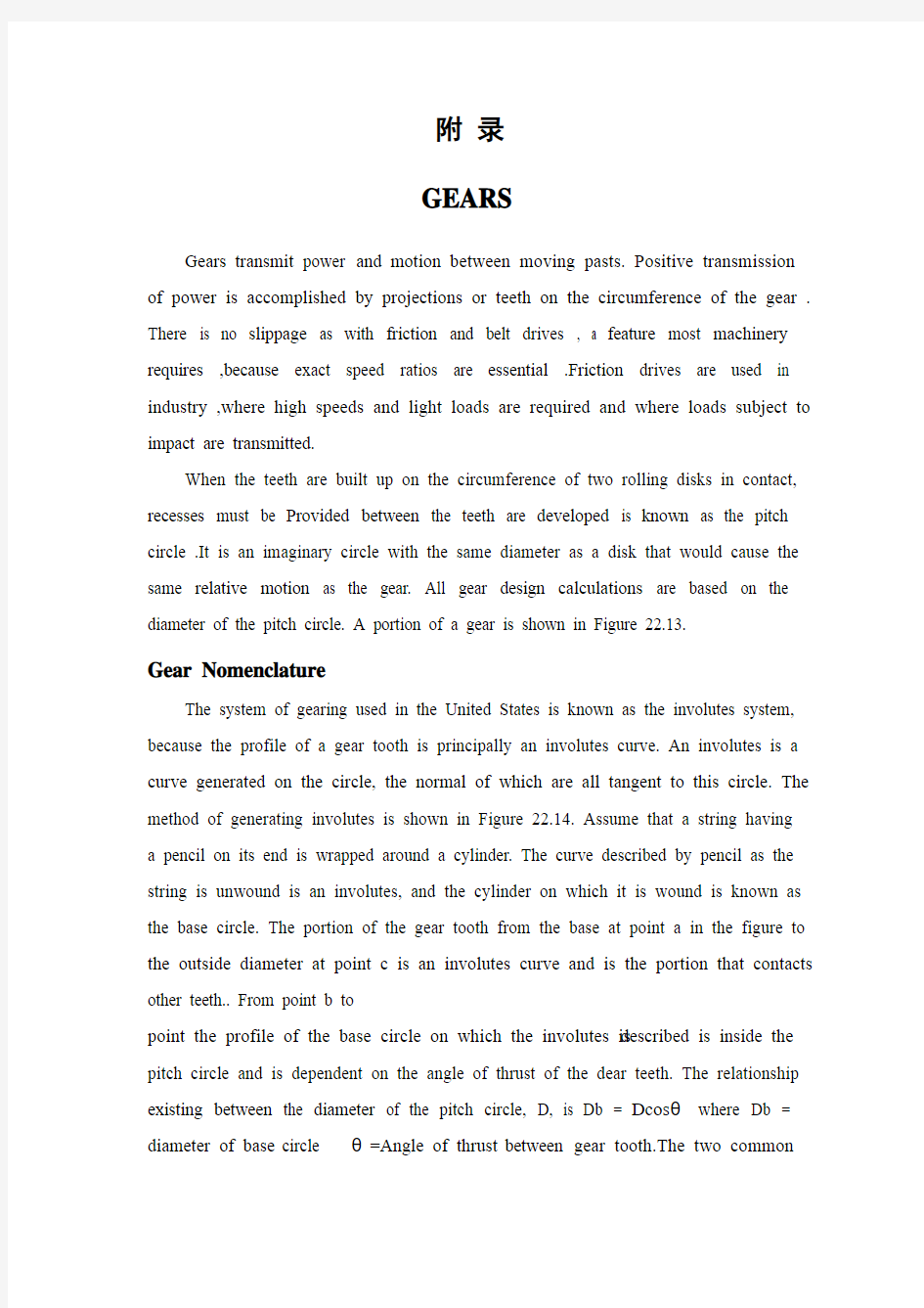
When the teeth are built up on the circumference of two rolling disks in contact, recesses must be Provided between the teeth are developed is known as the pitch circle .It is an imaginary circle with the same diameter as a disk that would cause the same relative motion as the gear. All gear design calculations are based on the diameter of the pitch circle. A portion of a gear is shown in Figure 22.13.
Gear Nomenclature
The system of gearing used in the United States is known as the involutes system, because the profile of a gear tooth is principally an involutes curve. An involutes is a curve generated on the circle, the normal of which are all tangent to this circle. The method of generating involutes is shown in Figure 22.14. Assume that a string having a pencil on its end is wrapped around a cylinder. The curve described by pencil as the string is unwound is an involutes, and the cylinder on which it is wound is known as the base circle. The portion of the gear tooth from the base at point a in the figure to the outside diameter at point c is an involutes curve and is the portion that contacts other teeth.. From point b to
point the profile of the base circle on which the involutes is described is inside the pitch circle and is dependent on the angle of thrust of the dear teeth. The relationship existing between the diameter of the pitch circle, D, is Db = Dcosθwhere Db = diameter of base circle θ=Angle of thrust between gear tooth.The two common
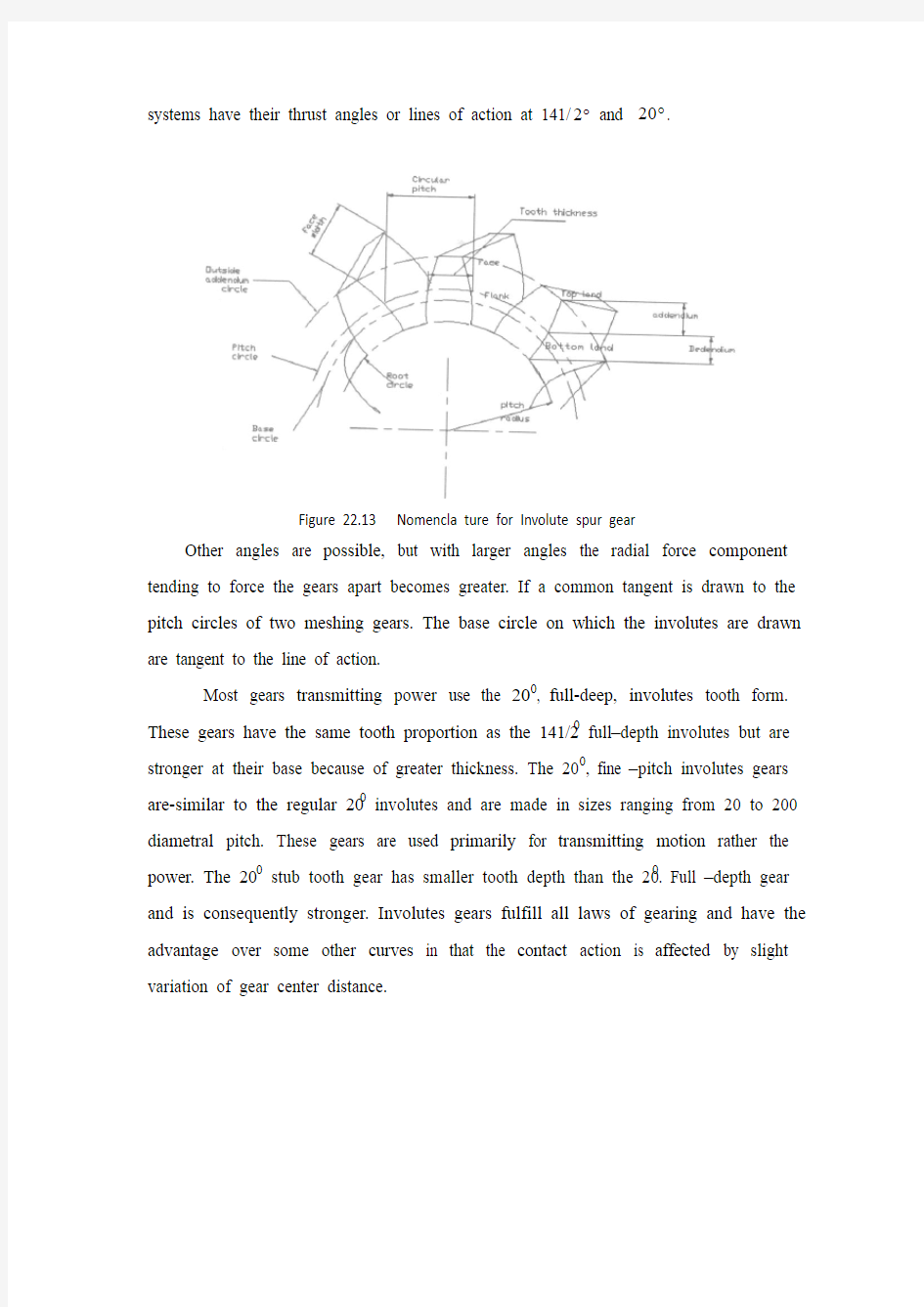
systems have their thrust angles or lines of action at 141/2?and 20?.
Figure 22.13 Nomencla ture for Involute spur gear
Other angles are possible, but with larger angles the radial force component tending to force the gears apart becomes greater. If a common tangent is drawn to the pitch circles of two meshing gears. The base circle on which the involutes are drawn are tangent to the line of action.
Most gears transmitting power use the 200, full-deep, involutes tooth form. These gears have the same tooth proportion as the 141/20 full–depth involutes but are stronger at their base because of greater thickness. The 200, fine –pitch involutes gears are-similar to the regular 200 involutes and are made in sizes ranging from 20 to 200 diametral pitch. These gears are used primarily for transmitting motion rather the power. The 200 stub tooth gear has smaller tooth depth than the 200. Full –depth gear and is consequently stronger. Involutes gears fulfill all laws of gearing and have the advantage over some other curves in that the contact action is affected by slight variation of gear center distance.
Figure 22.14 Mothod of genera an Involute tooth surface
The nomenclature of a gear tooth is illustrated in Figure 22.13. the principal definitions and tooth parts for standard 141/20 and 200 involutes gears are discussed here.
The addendum of a tooth is the radial distance from the pitch circle to the outside diameter of addendum circle. Numerically, it is equal to 1 divided by the diametral pitch P.
The addendum is the radial distance from the pitch circle to the root or addendum circle. It is equal to the addendum plus the tooth clearance.
Tooth thickness is the thickness of the tooth measure on the pitch circle. For cut gears the tooth thickness and tooth space are equal. Cast gears are provided with some backlash, the difference between the tooth thickness and tooth space measured on the pitch circle.
The face of a gear tooth is that surface lying between the pitch circle and the addendum circle.
The flank of a gear tooth is that surface lying between the pitch circle and the root circle.
Clearance is a small distance provided so that the top of a meshing tooth will not touch the bottom land of the other gear as it passes the line of centers.
Table 22.2gives the proportions of standard 141/200 involutes gears expressed in term of diametral pitch P and number of teeth N.
Table 22.2 American Gear Manufactures Association Standard for Involute Gearing
Pitch of Gears
The circuit pitch p is the distance from a point on one tooth to the corresponding point on an adjacent tooth, and is measured on the pitch circle. Expressed as an equation.
Metrical gearing is based on the module(mod) instead of the diametral pitch p, as in the English system. The basic metric module formula is mod =D/N=amount of pitch diameter per tooth =millimeters per tooth measured on the pitch diameter. Also, mod=1/p is expressed in millimeters. Also, mod p=25.4.
P = πD/N where D = diameter of the pitch circle
N = number of teeth
The diametral pitch p, often referred to as the pitch of a gear is the ratio of the number of teeth to the pitch diameter. It may be expressed by the following equation: P = N/D
Upon multiplying these two equations the following relationship between circular and diametral pitch results.
Hence,knowing the value of either pitch we may obtail the other by dividing into π.
Gears and gear cutters are standardized according to diametral pitch. This pitch can be expressed in even figures or fractions. Circular pitch, being an actual distance,
it is expressed in inches and fractions of an inch. A 6-inth gear (6diametral pitch) is one that has 6teeth per inch of pitch diameter . If the pitch diameter is 3 inch, the number of teeth is 3 x 6 or 18.The outside diameter of the gear is equal to the pitch diameter plus twice the addendum distance or 3 in.+2 x 1/6,which is 3.333in.
Any involutes gear of a given diametral pitch will mesh properly with a gear of any other size of the same diametral pitch. However, in cutting gears of various diameters a slight difference in the cutter is necessary to allow for the change in curvature of the involutes as the diameter increases. The extreme case would be a rack tooth ,which would have a straight line as the theoretical tooth profile. For practical reasons the number of teeth in an involutes gear should not be less than 12.
Gear speed
The speeds in rooms ,s and S, of two meshing gears vary inversely with both the pitch diameter and the number of teeth .This may be expressed as follows:
Figure 22.15 Nomenclature for meshing gear and pinon
s/S = D/d =T/t
where Dand d represent pitch diameter as included as indicated in Figure 22.15.T and t represent number of teeth on the gear and pinion.
Center distance : L = (D+d)/2
The speed ratio for a worm gear set depends on the number of teeth on the gear and the lead of the worm. For a single=threaded worm the ratio is
Rpm worm/rpm gear = T/t
Kinds of gears
The gears most commonly used are those that transmission power between two parallel shafts. Such gears having their tooth elements parallel to the ratating shafts
are known as spur gears, the smaller of the two being known as a pinion (Figure 22.15).If the elements of the teeth are twisted or helical,as known in figure 22.16B,they are known as helical gears. These gears amay be for connecting shafts that are at an angle in the same or different planes. Helical gears are smooth acting because there is always more than one tooth in contact. Some power is lost because of end thrust, and provision must be made to compensate for this thrust in the bearings. The herringbone gear is equivalent to two helical gears, one having right-hand and the other a left-hand helix.
Figre 22.17 All elements of straight bevel converge at the one opex of the gears Usually, when two shafts are in the same plane but at an angle with one another, a bevel gear is used. Such a gear is similar in appearance to the frustum of a cone having all the elements of the teeth intersecting at a point, as shown in Figure 22.17. Bevel gears are made with either straight or spiral teeth. When the shafts are at right angles and the two bevel gears are the same size, they are known as miter gears (figure 22.16A). Hypoid gears, an interesting modification of bevel gears shown as Figure 22.16F, have their shaft at right angles by they do not intersect as do the shaft for bevel gears. Correct teeth for these gears are difficult to construct, although a generating process has been developed that produces satisfactory teeth. Zero gears (Figure 22.16D)have curved teeth but have a zero helical angle. They are produced on machines that cut spiral bevels and hypoids. Worm gearing is used where a large speed reduction is desired. The small driving gear is called a worm and the driving gear is called a worm and the driven gear a wheel. The worm resembles a large screw and is set in close to the wheel circumference, the teeth of the wheel being curving to
conform to the diameter of the worm. The shafts for such gears are at right angles but not in the same plane. These gears are similar to helical gears in their application, but differ considerably in appearance and method of manufacture. A worm gear set is shown in Figure 22.16C.
Rack gears, which are straight and have no curvature, represent a gear of infinite radius and are used in feeding mechanisms and for reciprocating. They may have either straight or helical teeth. If the rack is bent in the form of a circle, it becomes a bevel gear having a cone apex angle of 180oknown as crown gear. the teeth all converge at the center of the disk and mesh properly with a bevel gear of the same pitch. A gear with internal teeth, known as an annular gear, can be cut to mesh with either a spur or bevel gear, depending on whether the shafts are parallel or intersecting.
Methods of Making Gears
Most gears are produced by some machining process. Accurate machine work is essential for high-speed, long-wearing, quite-operating gears. Die and investment casting of gears has proved satisfactory, but the materials are limited to low-temperature-melting metals and alloys. Consequently, these gears do not have the wearing qualities of heat-treated steel gears. Stamping though reasonably accurate, can be used only in making thin gears from sheet metal.
Commercial methods employed in producing gears are summarized as follows: A: Casting 1.sand casting 2.Die casting 3.Precision and investment casting
B: Stamping
C: Machining 1.Formed-tooth process a. From cutter in milling machine b. From cutter in broaching machine c. From cutter in shaper 2.Template process 3.Cutter generating process a. cutter gear b. Hobbing c. Rotary cutter d. Reciprocating cutters simulating a rack
D: Power metallurgy
E: Extruding
F: Rolling
G: Grinding
H: Plastic molding
Form Tooth Process
A formed milling cutter, as shown in Figure22.18,is commonly used for cutting a spur gear. Such a cutter used on a milling machine is formed according to the shape of the tooth space to de removed. Theoretically, there should be a different-shape cutter for each size gear of a given pitch as there is a slight change in the curvature of the involutes. However, one cutter can be used for several gears having different numbers of teeth without much sacrifice in their operation. Each pitch cutter is made in eight slightly varying shapes to compensate for this change.
They vary from no.1, which is used to cut gears from 135 teeth to a rack, to no.8, which cuts gears having 12 or 13 teeth. The eight standard involutes cutters are listed in Table 22.3.
Setup of a milling machine to cut spur gears are illustrated in Figure 22.18. A discussion of this process is given the chapter on milling is an accurate process for cutting spur, helical, and worm gears. Although sometimes used for bevel gears, the process is not accurate because of the gradual change in tooth thickness. When used for bevel gears at least two cuts are necessary for each tooth space. The usual practice is to take one center cut of proper depth and about equal to the space at the small end of the tooth. Two shaving cuts are then on each side of the tooth space to give the tooth its proper shape.
Figure 22.18 Setup for cutting a spir gear on a milling machine
Table 22.3 Standard Involute cutters
No.1135 teeth to a rack
No.255 to 134 teeth
No.335 to 54 teeth
No.426 to 34 teeth
No.521 to 25 teeth
No.617 to 20 teeth
No.714 to 16 teeth
No.812 to 13 teeth
The formed-tooth principle may also be utilized in a broaching machine by making the broaching tool conform to the teeth space. Small internal gears can be completely cut in one pass by having a round broaching tool made with the same number of cutters as the gear has teeth. Broaching tool is limited to large-scale production because of the cost of cutters.
齿轮
运动部件之间的能量和运动由齿轮来传递。主运动的能量由齿轮四周的凸台或齿相啮合来传递。由于摩擦和带传动,齿轮之间的传递无滑移。因为传递需要准确的速度,摩擦传动被广泛应用于工业,如高速,轻载以及载荷连续的地方。
为了保持两个相啮合的齿轮以及消除干涉,两个相啮合齿轮之间应该留有一点的间隙。向上延伸就是众所周知的节圆。节圆是个假想的圆,载以此为半径的圆上可以实现齿轮相啮合。因此所有的齿轮的设计计算建立载节圆之上的。齿轮的部分如图 2.2.13所示。
齿轮专业术语
由于齿轮的轮廓为渐开线,所以载美国齿轮系统称之为渐开线系统。渐开线是一条产生于圆且所有的曲线垂直圆的曲线。渐开线的产生方法如图22.14 所示。假设一个旋转的铅笔的一端饶在一个圆柱上,随着铅笔的旋转,未被破坏的曲线即为渐开线,而被破坏的为基圆。从如图所示的基圆上的a点到外圆上的c 点为渐开线曲线的一部分,在这部分上齿轮相啮合。从b点到a点以及到根圆的倒角部分为一段射线。渐开线的基圆在节圆的内部,同时基圆的位置决定了齿轮的压力角。节圆和基圆直径之间有如下关系:
Db = Dcosθ(Db为基圆的直径,θ为齿轮的压力角)。现在广泛运用的两个压力角(或作用线)为140/2o和20o,其他的角度也是可能的,但是跟随角度的变大。如果对于两个相啮合的节圆的线相切,压力角(或作用线)以140/2o为好,这时在基圆上所有的渐开线与作用线相切。
大多数传递动力的齿轮使用压力角为20o,全切深的渐开线齿轮。20o渐开线齿轮和140/2o的渐开线齿轮具有相同的齿部分,但由于20o的基圆上有较厚的齿,因而强度更高。如同标准的20o齿轮一样,20o精切节圆渐开线齿轮有从20到200大小不等直径的节圆的齿轮。这些齿轮主要用于传递运动而非能量。与20o全切深的齿轮相比较,20o的轻型的齿轮有着较浅的切屑深度,但是强度更高。渐开线齿轮满足齿轮设计的所有的原理,因为作用线不受齿轮中心距的变化而受到影响,因为必其他的曲线轮廓更加的有利于齿轮的啮合。
如图22.13所示,对齿轮的相关的术语进行了阐述。同时液讨论了标准的20o和141/20o齿轮渐开线齿轮的规律定义以及齿的各部分进行了说明。定义如下:
齿顶高为节圆到齿顶圆之间的距离,数值上等于1除以节圆直径P。
齿根高为节圆到齿根圆(或齿根高)之间的距离,其等于齿顶高乘以齿间隙。齿厚为在节圆上测量得到的齿的厚度。对于切削齿轮,齿厚和齿间隙是相等的。然而对于铸造齿轮,由于提供了一定的缓冲,因而对于在节圆上齿厚和齿间隙的测量有一定的区别。
齿轮的前刀面为位于节圆和齿顶圆之间的面。
齿轮的后刀面为位于节圆和齿根圆之间的面。
间隙为以各小的距离,他的提供是为了在经过中心线时,两个相啮合的齿轮不发生干涉(啮合齿轮的顶部不与令一个齿轮的根部相撞)。
表22.2根据节圆直径P和齿数N给出了141/20o和20o标准的渐开线齿轮的部分的数据。
齿轮节圆
齿距P为从齿轮的一侧的一点刀另外一个相邻点之间的距离,通常在节圆上测量大小。方程式为:
P = πD/N(D等于节圆的直径,N等于齿的数目)
节圆直径P,通常指的是在节圆上,齿轮的齿数除以节圆的直径。方程式如下:
P = N/D
如果将上式相乘可以得到齿距和节圆直径之间的如下关系:P=π。因此,如果我们知道了两者之间的任何一个值,就可以通过除以π得到令一个值。
齿轮和齿轮的加工根据不同的节圆直径可以实现标准化。节圆可以通过数字或者分数来表示。由于齿距是一个实际的距离,因此可以以英寸或者是几英寸表示。一个6节圆齿轮为在节圆直径上每英寸6个齿的齿轮。如果节圆的直径为3英寸,则齿数为三乘以六为十八。外圆直径等于节圆直径乘以2倍的齿顶高,或
者3+1x1/6=3.333英寸。
任意给定节圆直径的渐开线齿轮将与同节圆直径的任意尺寸的齿轮正确的啮合。然而,在加工不同直径的切削齿轮时,在切削过程中,随着直径的增加,渐开线的曲率发生轻微的变化时必须的允许的。但是齿条时一个特例,如果为理论的齿形,齿条应该为以条直线。但是由于实际的原因,一个渐开线齿轮的齿数则必须的大于12。
齿轮速度
对于s和S两个齿轮来说,两个相啮合的齿轮的速度(rpms)与节圆直径和齿数成反比。表达方程式为:s/S=D/d=T/t。如图22.15所示,D、d代表节圆的直径,T、t代表大齿轮和小齿轮的齿数,中心距:L=(D+d)/2
对于蜗轮蜗杆的速度由齿轮齿数和蜗杆的头数决定。对于单线蜗杆比率如下所示:(rpms orm)/(rpm gear) = T/1
齿轮种类
最普通使用的齿轮为传递动力的平行轴齿轮。其中齿轮轴平行于旋转轴的称为直齿轮,如图22.15 所示,两个齿轮中较小的称为小齿轮。如图22.16 所示,如果齿轮示扭曲或斜的,,则称为斜齿轮,所有齿轮的命名与在同一平面或不在同一平面成什么样的角度相联系。斜齿轮由于总是超过一个齿轮在啮合,所以应该采取一些措施来补偿根切的影响。人字形齿轮等价于两个斜齿轮,其中一个为右手系,另一个为左手系齿轮。
通常,当两个轴在同一平面内,同时彼此之间有一定的角度时,使用斜齿轮。这样的齿轮表面与所有齿轮的齿形延长线相交于一点的圆锥一样,图形如22.17所示。通常斜齿轮的形状为直齿或者是螺旋形齿。当两轴之间的角度为90o时,同时这两个斜齿轮有相同的尺寸,我们称之为等径伞齿轮(如图22.16A所示)。如图22.16F所示的偏轴伞齿轮,是对斜齿轮有趣的修改,虽然斜齿轮之间的角度为90o,但是并不相交。虽然对于齿轮,使人满意的加工方法不断的发展,但是制造准确的齿形仍然使困难的。零度齿轮(如图22.16D所示)有曲线的齿,斜齿的角度为零度,它通过在机器上加工螺旋形斜齿和偏轴伞齿轮得到所要求的齿轮。对于蜗轮蜗杆,常被用于快速降速的地方。小的驱动的齿轮为蜗杆,被驱动的齿轮为蜗轮蜗杆好象一个大的螺栓,紧紧地束缚在蜗轮的四周上,被切削的蜗轮齿与螺杆的直径相对应。蜗轮蜗杆的轴之间呈90o,但不在同一平面内。它的工作原理和斜齿轮的工作原理非常类似,但是表面和加工的方法有着明显的区别。蜗轮蜗杆的形状如图22.16C所示。齿轮齿条为直的、无曲率、且半径无穷大的齿轮,被广泛的应用于机械的进给运动和往复运动之中。他们可以是直齿或者是斜齿。如果齿条弯成一个圆,则它就成为众所周知的冠齿轮,冠齿轮的圆锥的最高角度可以是180o,所有的齿的延长线汇集于中点,能够和相同节圆的斜齿轮进行正确的啮合。对于内齿轮来说,是一个内齿的齿轮,根据轴是平行还是相交的不同,可以加工出与直齿轮或斜齿轮啮合的齿轮。
齿轮的加工的方法
大多数的齿轮的加工由普通的机床进行加工。为了获得高速,耐磨,稳定的齿轮,用精密的机床进行加工也是很有必要的。因此,模板成型和销蚀模使齿轮的加工发展到了令人满意的程度,但是其加工的材料仅限于低熔融的金属和合金。同时,没有热加工钢铁齿轮耐磨的性质。虽然模锻的精度很高,但是仅能制造板金类的精细齿轮。商用的加工齿轮的方法如下所示:
A 铸造
1 砂型铸造
2 压模铸造
3 精密和销蚀模铸造
B 冲压
C 机械加工
1 成型加工a 铣床成型加工b 拉床成型加工c 牛头刨床成型加工
2 模板加工
3 切削加工 a 刨床切削加工 b 滚齿加工 c 旋转切削加工 d 往复切削加工齿条
D 冶金加工
E 挤压加工
F 磨削成型
G 磨削成型
H 塑料模具成型
成型齿轮刀具加工
如图22.18所示,通常一个成型的铣削用于直齿轮的加工。而使用的机床的型号由被切削的齿槽的形状来决定的。理论上来说,由于渐开线的曲率存在着轻微的变化,所以给定的节圆不同,则有不同的切削形状的切削刀具。然而,一种切削的方式就可以在没有任何缺陷的操作中加工出很多具有不同齿数的齿轮。每个切削的节圆根据形状的变化等分为八份,来补偿形状发生的变化。如表22.3所示,列出了8种标准的渐开线切削方式,变化的范围从NO.1的135齿到齿条,到NO.8的12齿或13齿。
如图22.18所示,阐明了切削直齿轮的铣床的安装,并详细介绍了关于铣床加工的过程。成型铣对于直齿轮和斜齿轮以及蜗轮蜗杆的加工十分的准确。虽然有时候也用于伞齿轮的加工,但是由于齿厚的不断变化,加工过程不是那么的准确。当用于伞齿轮的加工时,对于每个槽的加工,需要加工两次。通常实际中,先确定中心切削的正确的尺寸,其尺寸为齿轮小端的距离。对于齿槽的两边的加工,则通过两个剃齿刀的切削来得正确的齿形。
我们通过使用拉刀加工齿轮的齿向间隙可以看出成型刀具的加工的原理对于拉床也是适用的。小内齿轮可以根据有相同切削的齿数的齿轮进行多次的走刀而加工出来。但是由于切削的成本较高,拉削仅用于大规模的生产加工中。