过程装备与控制工程专业外语(原文+翻译)
- 格式:docx
- 大小:71.57 KB
- 文档页数:27

17th World Conference on Nondestructive Testing, 25-28 Oct 2008, Shanghai, ChinaA new fully digital system for RT inspection of metal tube to tube sheet jointsof heat exchangersUwe ZSCHERPEL 1, Oleksandr ALEKSEYCHUK 1, Peter ROST 2, Markus SCHMID 2, Konstantinos SPARTIOTIS 3, Alexander WARRIKHOFF 41 Division “NDT – Radiology”, BAM Berlin, GermanyPhone: +49 30 8104 3677, Fax: +49 30 8104 4657; e-mail: uwez@bam.de,oleksandr.alekseychuk@bam.de2 BASF SE; Ludwigshafen, Germany; e-mail: peter.rost@, markus.schmid@3 AJAT Oy, Espoo, Finland; e-mail: kostas@ajat.fi4 rtw RÖNTGEN-TECHNIK DR. WARRIKHOFF GmbH, Neuenhagen, Germany; email:sales@rtwxray.deAbstractA completely novel device was developed for RT inspection of weldments for tube to tube sheet joints on heat exchangers applied in chemical industry. It replaces the Gammamat B3 unit containing an Ir 192 isotope as radiation source and a punched NDT film (system class C3 acc. to EN 584) as detector to allow the one-sided access for inspection.In a first step a special X-ray tube with a rod anode was developed by rtw Röntgentechnik to replace the Ir 192 isotope source to achieve a better inspection sensitivity at 130 kV for thin walled tubes and tube sheets.A new specialized, direct converting detector based on CdTe was designed by Ajat Oy, Finland. Together with the X-ray source a handsome unit was designed with 4 detector tiles arranged around the rod anode, which passes though the detector plane.The handling of this novel inspection unit as well as the computer based image acquisition reduces the expense for this RT inspection considerably. All problems with film chemistry and isotope transportation are avoided. The computer based evaluation of the digital radiographs and the direct connection to the inspection data base of the complete heat exchanger create significant advantages for inspection planning and documentation. First experiences are reported on application of this new technique in the field.Key words: Radiographic inspection, digital detector arrays, one-sided access, tube to tube sheet joints, heat exchangers, chemical industry1.Conventional Inspection TechniqueSince decades state of the art is radiographic testing based on Gammamat B3 containing an Ir 192 isotope as radiation source and NDT film (typically system class C3 acc. to EN 584-1) as detector (see fig. 1). For this application packed films have to be punched light tight to pass the radio isotope source through the imaging plane caused by the one-sided accessibility of the tube sheet. Special wall thickness compensators are used to account for wall thickness changes in penetrating direction across the inspected weld regions. The sensitivity of this testing method is limited by the properties of the radiation source (energy and source size). Also the world wide shipment of radio isotopes gets more and more complicated.Fig.1: Gammamat B3 isotope source with film holder (left side) at inspection position and set-up for inspection of a small heat exchanger in the field (right side)The design, production and inspection of tube-to-tube sheet welds are regulated in the BASF specification E-S-MC 331. For high risk heat exchangers additional inspections by the owner of the heat exchanger (BASF) are required and realize the surveillance of the manufacturing during heat exchanger built-up. The specification requires random tests depending on the mechanical and thermal load of the heat exchanger (in percentage of welds to be tested and acceptance criteria for detected indications) on behalf of the future owner BASF. Depending on the results of the first random test a second random test after repair or a 100% test charged to the manufacturer may be necessary to reach the required weld quality.Typical source size is 1x0.5mm² Ir-192 isotope and 10x12 cm² punched C3 films are used with 0.02 mm Lead screens. The range of inspected tubes is from 16mm x 1.5mm up to 76mm x 4mm (diameter x wall thickness), pore sizes down to 1mm can be detected with this configuration.Fig.2: film exposure (left above) and corresponding cross sections by destructive testing (right side) showing typical flaws like porosities and notches2.The new rod anode X-ray tube /1/A new X-ray tube was developed by rtw Röntgentechnik Dr. Warrikhoff to achieve a better inspection sensitivity and to solve issues with world wide transport of radio isotopes. In Fig. 3this tube is shown. The main reason for this development was the limited detectability with Ir 192. Caused by the energy of the gamma rays the minimal detectable pore size is about 0.8mm in steel. For new materials like Ti enhanced flaw detection was requested.Fig. 3:Rod anode X-ray tube MCTS 130 - 0.6 (left side) and complete inspection setup with controller, right side: HV generator and X-ray tube with film holder (red) at a heat exchanger ready for single-sided inspectionThe rod has an outer diameter of 6 mm and a length of 40 mm, the focal spot is smaller than 1mm at 130kV and 2.4mA (max. 300 W). This new tube was successfully applied in combination with X-ray film and the enhanced detectability for new materials like Ti was proven, so the next step to replace the film was straight forward to omit the necessary chemical development procedure on-site.3.The digital detector array DIC100TH /2/Ajat developed the detector DIC100TH, which is a first of its kind, breakthrough digital imaging device for tube to tube-sheet weld inspection.The detector comprises four 25 mm x 25 mm CdTe-CMOS high resolution elements (100µm pixel size) operating at 50fps and arranged to allow a rod anode tube to pass through the mid-section of the device. The X-Rays are produced at the tip of the rod anode and emit in a direction towards the CdTe-CMOS detector (see fig. 4).The rod-anode tube is fed through the CdTe-CMOS active detector and the two are bound together in a robust mechanical arrangement which can be inserted in the heat exchanger for the tube to tube-sheet weld to be inspected (fig. 5).This image sensor provides for real time and on line tube to tube sheet weld inspection with excellent sensitivity, reliability and speed. The unit addresses requests to replace the traditional film based systems that today are used typically in this field with a real time digital inspection system.The basic spatial resolution and detector calibration limits the maximum contrast sensitivity of the detector. The basic spatial resolution is 100 µm for this direct converting detector and defined by the pixel size. To achieve the best detection sensitivity possible a special calibration procedure was developed. Caused by the strong dependence of X-ray intensity on the radial distance form the rod centre the rod anode X-ray tube cannot be used for pixel calibration of the detector. Also the temperature dependence of the detector calibration is not neglectable. As result of the developed calibration procedure (using a standard X-ray tube at 90kV, 1m distance and a 5 mm steel plate at the detector to generate a suitable flat field for detector calibration) calibrationsets are stored in dependence of the detector temperature in the range between 10°C and 32°C and selected automatically according to the real detector temperature in the field. In this manner the optimal detector calibration is maintained in the field.Fig. 4:The digital detector array DIC 100TH, left side: detector electronics showing the arrangement of the 4 detector tiles around the rod anode X-ray tube, right side: detector-X-ray unit ready for single-sided inspectionFig. 5: The fully digital inspection system with its two main parts (left side) and installed at a heat exchanger ready for inspection4.Software, complete inspection system and first resultsIn fig. 6 a snapshot of the developed user interface of the software is shown. A Laptop equipped with a Cameralink interface for detector connection and an RS-422 interface for control of the X-ray generator is used for image storage, evaluation and report generation. The complete system (X-ray tube and detector) is software controlled and complete configuration set-ups can be stored and re-activated for easiest handling. A list with inspection results is transferred directly to the data base “virtual tube” for documentation of the inspection. Digital filters can be applied for enhancement of flaw detection on the display.Fig. 6:snapshot of the developed software for system control, left side: image display and interactive selection of inspection result, middle: control program for X-ray tube set-up, integration time and description of inspection position, right side: visualization of inspection result summery for the whole heat exchanger (based on the data base virtual tube)A comparison of the achieved detection limits for the novel inspection systems is shown in fig. 7 based on a test mock-up with 25mm diameter pipes and 2mm steel wall thickness.Fig. 7: Comparison of inspection results on a steel test mock-up 25x2mm, left side: conventional system with Ir 192 and film, detection limit 0.8mm drill hole, middle: rod anode and film, detection limit 0.5mm drill hole, right side: rod anode and DIC100TH detector, detection limit better than 0.3mm drill hole.In fig. 8 an example of a real inspection result for a 25mm steel pipe with 2mm wall thickness is given. The visibility of the flaw indications can be improved by digital image processing of the images acquired from the detector.Fig. 8: comparison of inspection results of a real weldment on a heat exchanger 25mm/2mm at 80kV, 0.5mA and 30s exposure, left side: rod-anode and X-ray film, right side: DIC100TH detector and highpass filtering of digital imageField trials are on-going to gain experience with this novel inspection system and to prove the advantages and the extended application range in comparison with the classical set-up.5.ConclusionsAn improved inspection system for RT inspection of metal tube to tube sheet joints of heat exchangers was developed based on a unit combining a rod anode X-ray tube and a new digital detector array arranged in tiles around this rod anode. In this way the single-sided access for weld inspection was realized. The following advantages of this novel fully digital unit were proven: •no radioactive container transport and usage of film chemistry on-site at the heat exchanger production site•improved flaw detection•shorter inspection times•immediate inspection result•software supported evaluation of images•data base supported documentation of inspection results•reduced requirements for radiation protection, considerable smaller controlled area with75 kV X-ray voltage compared with Ir-192 requirements as used beforeThe experiences gained with the presented prototype system will result in optimised follow-up inspection systems.6.References/1/ www.rtwxray.de/2/ www.ajat.fi。
Unit 14化学工程的单元操作1.介绍化学加工可以包含各种各样的不同的过程顺序,它的原理是独立于我们的操作的材料和操作的系统,把复杂的工艺过程分解成单个的物理过程(即单元操作)和多种化学反应过程的实践,导致了化学工程的通用性。
单元操作的观念在化学工程是基于不同的过程步骤可以减少简单操作或反应,而这些反应在不考虑操作条件下有同样的基本反应。
这个原则,在美国化学工业的发展过程中变得明显,在1915年早些首次变得明显。
任何一个化学过程,无论所操作规模大小,可以被分解成单元作用的同等的一些系列,像粉碎,混合,加热,烘干,吸取,浓缩,析出,沉淀,结晶,过滤,溶解,电解等等。
基本单元操作的数量不是很大而且只有很少几个包含特定的操作,化学工程的复杂性源于各种条件如温度,压力等的多样性。
由于条件的变化,单元作用就必须在不同的过程中完成。
同时化学工程的复杂性还受到由反应物的物理及化学性质所决定的结构材料和设备设计的影响。
单元操作的开始清单列举了十二个功能,不是所有的都包含单元操作。
再增加的都会命名,在那些年处于适中的比率但是最近在一个加速的比率。
流体流动,热传递,蒸馏,加湿,气体吸收,沉积,分类,搅拌,和离心过滤已经被公认。
最近几年,新技术逐渐被理解,比较适用于过去但很少使用分离技术这导致了分离,处理,操作或者是介入制造的数量上的持续增长,这些可用于没有重大改变的各种进程。
这是根据一个术语”单元操作”,现在为我们提供了、一系列的技术合作。
2.单元操作的分类流体流动这涉及的原则,确定流动或运输任何流体从一个点到另一个点。
传热这个单元操作处理的原则是,积累和转让的热量和能量从一个地方到另一个地方。
蒸发这是一个特殊的情况下传热,其中涉及蒸发的挥发性溶剂,如水从一个非易失性溶质如盐或其它材料在解决方案烘干在这个操作中挥发液体,通常是水,从固体材料中挥发出去。
蒸馏这是一个过程即液态混合物的分离通过沸腾,因为它们的蒸汽压不同。


毕业设计(论文)外文文献翻译文献、资料中文题目:热扩散涂料换热器材料文献、资料英文题目:文献、资料来源:文献、资料发表(出版)日期:院(部):专业:过程装备与控制工程班级:姓名:学号:指导教师:翻译日期: 2017.02.14毕业设计(论文)翻译外文题目:DIFFUSION COATINGS FOR HEATEXCHANGER MATERIALS中文题目:热扩散涂料换热器材料DIFFUSION COATINGS FOR HEAT EXCHANGER MATERIALS热扩散涂料换热器材料V.Rohr和M.Schutze有一个需要发展清洁电力系统,以降低排放污染物。
这意味着一个增加换热器的最高温度管,这是现在的600摄氏度在眼下现代电厂。
为传统使用铁素体钢,但这种增长是有限的由钢的力学性能和耐腐蚀电阻在煤炭、浪费和生物量解雇的环境。
奥氏体钢和镍合金是潜在的基础候选人在较高的温度增加性能(700摄氏度.尽管如此,耐蚀性这些材料可以进一步提高应用涂料。
包胶结是最简单也是最省钱的涂层工艺之一。
然而,需要加热,目前正在执行步骤最低温度为750 - 800摄氏度。
显微组织可能的材料会显著的改变在这些温度下的涂装工艺,特别是对铁素体-马氏体钢。
由于组织显示机械性能,这些也可能受到涂装工艺的影响。
因此,有一个需要发展相对低温的包装过程。
摘要本文为P91对应铁素体钢和HCM12A,奥氏体钢合金800H和347型钢与17 Cr / 13镍、镍基合金IN617是温度低于以上提到的范围。
为了方便的渗透保护性的元素在涂装工艺、不同表面处理之前的申请过程的影响,探讨提高扩散路径的数量在金属地下区。
表面处理的影响等研磨或玻璃珠爆破对效率过程中详细讨论。
Rohr先生(rohr@dechema.de)和Schutze教授在这个DECHEMAKarl-Winnacker-Institut电动汽车,Theodor-Heuss-Allee 25岁,D - 60486 Frankfurt amMain,德国。
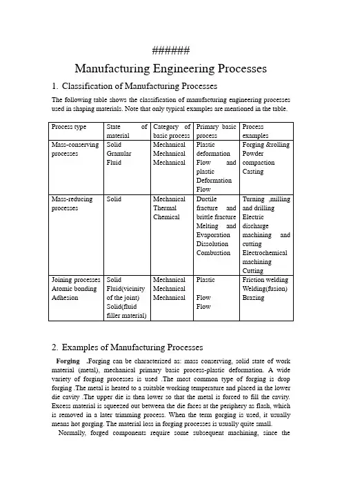
######Manufacturing Engineering Processes1.Classification of Manufacturing ProcessesThe following table shows the classification of manufacturing engineering processes used in shaping materials. Note that only typical examples are mentioned in the table.2.Examples of Manufacturing ProcessesForging .Forging can be characterized as: mass conserving, solid state of work material (metal), mechanical primary basic process-plastic deformation. A wide variety of forging processes is used .The most common type of forging is drop forging .The metal is heated to a suitable working temperature and placed in the lower die cavity .The upper die is then lower so that the metal is forced to fill the cavity. Excess material is squeezed out between the die faces at the periphery as flash, which is removed in a later trimming process. When the term gorging is used, it usually means hot gorging. The material loss in forging processes is usually quite small. Normally, forged components require some subsequent machining, since thetolerances and surfaces obtainable are not usually satisfactory a finished product. Forging machines include drop hammers and forging presses with mechanical or hydraulic drives. Es involve simple .The machines involve simple translatory motions.Rolling Rolling can be characterized as: mass conserving, solid state of material, mechanical primary basic process-plastic deformation. Rolling is extensively used in the manufacturing of plates, sheets, structural beams, and so on. An ingot is produced in casting, and then, in several stages of rolling it is reduced in thickness, usually while hot. Since the width of the work material is kept constant, its length is increased according to the reduction. After the last hot-rolling stage, a final stage is carried out cold to improve surface quality and tolerances and to increase strength. In rolling, the profiles of the rolls designed to produce the desired geometry.Powder Compaction Powder compaction can be characterized as; mass conserving, granular state of material, mechanical primary basic process-flow and plastic deformation. In this context, only compaction of metal powder is mentioned, but generally compaction of molding sand, ceramic materials, and so on, also belong in this category.In the compaction of metal powders, the die cavity is filled with a measured volume of powder and compacted at pressures typically around 500N/mm2. During this pressing phase, the particles are packed together and plastically deformed. Typical densities after compaction are 80% of the density of the solid material. Because of the plastic deformation, the particles are”welded” together, giving sufficient strength to withstand handling. After compaction, the components are heat-treated—sintered—normally at 70%~80% of the melting temperature of the material. The atmosphere for sintering must be controlled to prevent oxidation. The duration of the sintering process varies between 30 min and 2h. The strength of the components after sintering can, depend on the material and the process parameters closely approach the strength of corresponding solid material.The die cavity, in the closed position, corresponds to the desired geometry. Compaction machinery includes both mechanical and hydraulic presses. The production rates vary between 6 and 100 components per minute.加工工艺过程1.加工工艺过程的分类2.锻造工艺过程分类锻造锻造过程的特性可表述如下,质量守恒,工作材料为固态,力学基本过程为塑性变形过程。
过程装备与控制工程英语1.过程装备(Process equipment)The process equipment in the factory is responsible for manufacturing products efficiently.2.控制工程(Control engineering)Control engineering plays a crucial role in ensuring the stability and reliability of industrial processes.3.设备(Equipment)The factory invested in state-of-the-art equipment to improve production efficiency.4.流程(Process)The production process includes multiple stages, each with its own specific requirements.5.控制(Control)The control system allows operators to monitor and adjust various parameters for optimal performance.6.自动化(Automation)Automation has greatly improved efficiency in manufacturing processes.7.传感器(Sensor)Sensors are used to collect real-time data and provide feedback for control purposes.8.测量(Measurement)Accurate measurement of process variables is crucial for maintaining quality standards.9.监控(Monitoring)Continuous monitoring of process parameters is essential for early detection of issues.10.仪表(Instrumentation)Instrumentation plays a vital role in collecting and displaying data from various sensors in a process.11.采样(Sampling)Regular sampling of raw materials ensures their quality meets the required standards.12.环境监测(Environmental monitoring)Efficient control engineering systems enable real-time environmental monitoring.13.压力(Pressure)The pressure in the system is carefully controlled to ensure stable operation.14.温度(Temperature)Temperature control is crucial for maintaining the desired chemical reaction rate.15.流量(Flow rate)Monitoring and controlling the flow rate of liquid or gas is important for process efficiency.16.液位(Liquid level)Accurate measurement of liquid level ensures proper functioning of the process.17.控制阀(Control valve)Control valves regulate the flow rate or pressure offluid in a process.18. PLC (Programmable Logic Controller)PLCs are widely used in control engineering to automate and monitor industrial processes.19.数据采集(Data acquisition)Data acquisition systems collect and record data from various sensors for analysis.20.仪器仪表校准(Instrument calibration)Regular instrument calibration ensures accurate measurement and control.21.故障诊断(Fault diagnosis)Advanced control engineering systems can detect and diagnose faults in real-time.22.实时控制(Real-time control)Real-time control engineering allows for immediate adjustments to process conditions.23.可靠性(Reliability)Reliability is a key factor in choosing process equipment and control systems.24.自适应控制(Adaptive control)Adaptive control algorithms constantly adjust process parameters to optimize performance.25.能源管理(Energy management)Efficient control engineering strategies can help optimize energy consumption in industrial processes.。
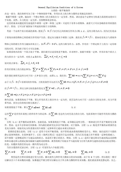
General Equilibrium Conditions of A System力系的一般平衡条件在这一部分,我们将研究为了使一个物体保持平衡,作用在其上的力和力偶所必须满足的条件。
根据牛顿第一定律,施加在一个静止物体上的力系的合力一定为零。
然而,请注意这个定律对力矩或力系的转动效应只字未提。
显然,合力矩也一定为零,否则物体将会转动。
这里的基本问题是原先叙述的牛顿第一定律(和第二定律)只适用于非常小的物体,或者尺寸可以忽略的非零质量的粒子。
然而,它可以扩展到如下所述的有限尺寸的物体。
考虑一个由两个质点组成的系统,假设1f 和2f 为它们之间的相互作用力(图.1.1)。
这些力称为内力,因为它们是由于系统内部的物体之间的相互作用而产生的。
假定内力服从牛顿第三定律,我们有12f f =-。
假如还有质点与系统外物体之间的相互作用力施加在质点上,如1,2F F 和3F ,这些力称为外力。
显然,作用在一个特定粒子上的力一定有相同的应用,因为粒子的尺寸可以忽略。
如果系统内的每一个质点处于平衡,我们就可以说系统是平衡的。
在本例中,依据牛顿第一定律,作用在每个质点上的力的合力一定为零。
对质点A 我们有:∑=++=0121f F F F A 而对质点B 有:∑032=+=F f F B作用在系统上的力的总和为:123120A B F F F F F F f f =+=++++=∑∑∑现在我们来研究这些力对于同一点P 的合力矩。
由图1.1,我们有:12()()P A B M r F r F =⨯+⨯∑∑∑ 由于力1f 和2f 有相同的作用线,力矩的条件可以改写为1121223()0P M r F F f f r F =⨯++++⨯=∑ 但12f f =-;所以力和力矩的条件简化为1210F F F F +=+=∑ 和111223()()()0P M r F r F r F =⨯+⨯+⨯=∑换句话说,如果系统处于平衡,那么作用在其上的合外力一定为零,而且这些力对于任一点的合力矩也为零。

Reading Material 5Static and Dynamic Balance of Rotating BodiesThe unbalance of a single disk can detected by allowing the disk to rotate on its axle between two parallel knife-edges, as shown in Fig.1.22. The disk will rotate and come to rest with the heavy side on the bottom. This type of unbalance is called static unbalance, since it can be detected by static means.In general, the mass of a rotor is distributed along the shaft such as in a motor armature or an automobile-engine crankshaft. A test similar to the one above many indicate that such parts are in static balance, but the system may show a considerable unbalance when rotated.As an illustration, consider a shaft with two disks, as shown in Fig. l. 23. If the two unbalance weights are equal and 180 deg. apart, the system will be statically balanced about the axis of the shaft. However, when the system is rotated, each unbalanced disk would set up a rotating centrifugal force tending to rock the shaft on its bearings. Since this type of unbalance results only from rotation we refer to it as dynamic unbalance.Fig. 1. 24 shows a general case where the system is both statically and dynamically unbalanced. It will now be shown thatthe unbalanced forces P and Q can always be eliminated by the addition of two correction weights in any two parallel planes of rotation.Consider first the unbalance force P, which can be replaced by two parallel forces and . In a similar manner Q can be replaced by two parallel forces and . The two forces in each plane can then be combined into a single resultant force that can be balanced by a single correction weight as shown. The two correction weights C1 and C2 introduced in the two parallel planes completely balanced P and Q, and the system is statically and dynamically balanced. It should be further emphasized that a dynamically balanced system is also statically balanced. The converse, however, is not always true; a statically balanced system may be dynamically unbalanced.Example A rotor 4 in. long has an unbalance of 3 oz.in. in a plane 1 in. from the left end, and 2 oz. in. in the middle plane. Its angular position is 90 deg. in the clockwise direction from the first unbalance when viewed from the left end. Determine the corrections in the two end planes, giving magnitude and angular positions.Solution. The 3-oz. in. unbalance is equivalent to oz. in. at the left end and oz. in. at the right end, as shown in Fig. 1. 25. The 2 oz. in. at the middle is obviously equal to l oz. in. at the ends.Combining the two unbalances at each end, the corrections are: Left end:OZ.in.to be removedclockwise from plane of first unbalanceRight end:OZ.in.to be removedclockwise from plane of first unbalance第一个不平衡点的逆时针方向阅读材料 5旋转体的静态和动态平衡单一圆盘的失衡可以通过使平行于轴的两根刃行支撑的转动来检测到,如图1.22所示。
Unit 13 Principles of Heat TransferPractically all the operations that are carried out by the chemical engineer involve the production or absorption of energy in the form of heat. The laws governing the transfer of heat and the types of apparatus that have for their main object the control of heat flow are therefore of great importance.实际上,所有的由化学工程师进行的操作都要涉及热量的产生和吸收。
因此,控制传热的定律和以控制热流为主要目的的仪器类型都是很重要的。
1. Nature of Heat FlowWhen two objects at different temperatures are brought into thermal contact, heat flows from the object at the higher temperature to that at the lower temperature. The net flow is always in the direction of the temperature decrease. The mechanisms by which the heat may flow are three, conduction, convection, and radiation.当两种不同温度的物体开始接触后,热流就会从高温物体传给低温物体。
净热流总是随着温度降低的方向。
传热的机理通常分三种:热传导,热对流,热辐射。
装控131 杨哲1304310125CORROSION AND ANTICORROSION TECHNOLOGYIN OFFSHORE PLATFORMS(Shanghai Shipbuilding Technology Research Institute, CSSC 200032, China) Abstract: This paper summarizes the corrosion environment and rules of the different zones in offshore platforms, also briefly introduces the requirements and systems of the anticorrosion coating .According to the long-term anticorrosion requirements in offshore platforms, the paper introduces several long-term anticorrosion technology, including thermal spraying, adding zinc protection and anticorrosion technology with platform legs wrapped etc,which will provide some references to the research of the long-term anticorrosion technology in offshore platforms.Key words:offshore platform;anticorrosion; thermal spraying; adding zinc technology; anticorrosion wrapOffshore platform is a kind of large offshore engineering structure. The steel structure in the long-term salt fog, moisture and water environment, the erosion of seawater and sea creatures, and produce severe electrochemical corrosion. Corrosion seriously affects the mechanical properties of the structure of the offshore platform, which affects the safety of the marine platform. And because the offshore platform off the coast, not as a regular maintenance like a ship docking, so builders and users of offshore platforms very seriously corrosion of marine platform. How long-term preservation of offshore platform structure, as well as research and development of offshore platform structure of the new materials, new technologies and new processes are of long-term preservation is very important.1. Corrosion Rules 1 offshore platform1.1 Corrosion regional boundaries of the marine environmentOffshore platforms extremely harsh environment, sun exposure, salt spray, shock waves, complex water system, environmental temperature and humidity changes and marine life make offshore platforms erosion corrosion rate faster. Offshore platforms in different marine environments, corrosion behavior and corrosion characteristics will be relatively large differences. Therefore, to offshore platform structure in a marine environment corrosion corroded areas were analyzed and defined, in order to put forward effective protection measures. According to the marine environment, corrosion characteristics and different average corrosion rate, offshore platform in the marine environment in marine atmosphere can be divided into three major regions splash zone and immersion zone. In order to better analyze the corrosion of steel offshore platforms, many researchers turn splash zone into the splash zone and tidal zone, immersion zone into seawater immersion zone and seabed soil area that is divided into five areas of corrosion.1.2Marine steel corrosionOcean-atmosphere:Ocean sea-salt particles cause atmospheric zone accelerate corrosion, dry surface and wet film alternates salt form of physical, chemical and electrochemical action affecting metal corrosion.Splash Zone:The most serious corrosion in the marine environment, the site is above average tide splash zone. As often as the wet surface, surface oxygen supply issufficient, no sea biofouling. Long and short drying surface wetting the surface of the alternation and spray erosion, mainly caused by physical and electrochemical corrosion damage and maximum damage.Tidal zone: steel corrosion tidal area is the lowest, even less than the corrosion rate of seawater immersion and seabed soil. The average low tide level the following corrosion nearby area emergence of a peak, it is because steel piles in the marine environment, with tidal fluctuations, the total amount of oxygen in the steel surface above the waterline humid than dip below the waterline at sea the steel surface to be much more fully, and to each other to form a loop, thereby becoming an oxygen concentration difference between the macro corrosion cell. Corrosion cell-enriched zone is the cathode, namely tidal area; relatively anoxic zone anode, namely the regional average low tide level below the waterline. The overall effect is that at every point throughout the tidal zone are subject to varying degrees of cathodic protection. While the average low tide level less often as the anode and the emergence of corrosion peak.Seawater immersion zone:the corrosive seawater immersion zone, the shallow water may corrode more quickly than the ocean air, the oxygen content of the deep-sea areas is often much lower than the surface, the water temperature close to 0 oc, corrosion lighter.Seabed soil zone: the presence of sulphate reducing bacteria and bacterial sources and characteristics of seafloor sediments mixed. Less influence by the sea, and the temperature is low, a small degree of corrosion, but there is some corrosion at the junction of ocean currents action.2 offshore platform steel structure anti-corrosion coating technologyLong-term offshore platforms in harsh corrosive environments, maintenance difficulties during use, so only use anti-corrosion technology provision of high-performance heavy-duty coatings. Several offshore platform using heavy-duty coatings, each with the following characteristics:(1) zinc-rich primer: Requires a high proportion of zinc-containing paint, Kuang requirements and substrate adhesion. One role is to take zinc-rich primer cathodic protection, In addition, when the coating damage or when there is not continuous, zinc Yao can play the role of sacrificial anode to protect the substrate. A zinc-rich primer T ong inorganic zinc-rich primer, epoxy zinc-rich primer and the like.(2) intermediate paint: intermediate paint requires comprehensive anti-corrosion ability, among cattle is characterized by anti-rust paint or impervious material containing material efficient, female l granular or scaly zinc powder, glass flake, stainless steel flake, satisfied Mu class Chin shielded and powder-based coatings and cathodic protection type were kind of new corrosion-type paints and so on.(3) Finish: finish the role is to provide a protective layer of primer and intermediate coat, slowed down and limited water vapor, oxygen, and chemical activity of ion penetration. Also requires impact resistance, anti-aging and anti-insoluble and so on. Finish commonly used chlorinated rubber, vinyl, polyurethane or acrylic resin coatings.In addition, heavy-duty anti-corrosion coating to get a good effect, but also need to pay attention to a number of factors, including the surface treatment of the substrate, high-quality paint, reasonable coating system, outside construction conditions,construction coating quality control. Currently heavy-duty coatings mainly used for offshore platforms atmospheric zone.3.Several long-term preservation technology offshore platform structureFor each area of corrosion offshore platforms, in addition to the current anti-corrosion coating and cathodic protection or impressed current cathodic protection system support, but also. on the offshore platform have long-term preservation of the use of other technologies, including long-term platform for thermal spraying anti-corrosion technology, Zinga protection technology, the platform leg tied corrosion package technology.3.1 offshore platforms thermal spraying anti-corrosion technologyThermal spraying technology in offshore platform steel member has a long history. Thermal spraying of zinc, aluminum and its alloys coating on foreign offshore platform steel member has successfully applied examples, examples show: thermal spray coating of zinc-aluminum and its alloys corrosion has become a mature technology, after appropriate heat sealed spray zinc-aluminum coating at room temperature and high temperature on steel in the splash zone exhibited excellent corrosion resistance.Aluminum thermal spray coatings in marine engineering is the biggest application platform in 1984 to build the H otton tension leg platform. The platform design life of 50 years. 8 years after its use in the splash zone corrosion is found, and brown leakage effects. Thickness measurement showed that the thickness of the coating does not reduce platform installation, it illustrates the effect of anti-corrosion marine platform lame spraying zinc aluminum metal coating layer is obvious, even if the surface of the organic coating off will ensure expansion of the substrate against corrosion. At the same time after tests showed that 2001} hot Tut m thick zinc-aluminum coating for steel in the splash zone protection can ensure life for more than 30 years.For high-strength steel parts used for offshore platforms, spraying aluminum and aluminum alloy coating not only provides an aluminum shield, and once the coating is damaged, it can appear as a sacrificial anode protection drain coating area. The coating may be applied in a closed paint, aluminum and aluminum alloy coating to seal the pores, thereby improving coating performance and extend the life of its total. Our thermal spraying anti-corrosion technology started late, currently used in offshore platform preservative it is still in the experimental stage, pending further development and application.3.2 Zinga offshore platform protection technologyZinga protection is a quality and convenient method for steel corrosion protection, zinc add protection to the substrate material has cathodic protection and shielding dual role. Zinga protection technology has excellent corrosion resistance that Zinga zinc galvanized coating dry film amounted to 9600, the product purity over 99.995% zinc. Zinga protection also has a unique blend of heavy, new and existing coating Zinga Zinga coating can be fully integrated, easy maintenance painted up.Zinga protection compared with conventional organic coatings, cathodic protection has a strong effect and may be used as a good bottom, its resistance to corrosion than conventional zinc-rich primer 5-6 times, corrosion protection up to 25 years to 30 years.The extent of corrosion of offshore platforms immersion zone serious than theatmospheric region, but lighter than the splash zone. Full immersion zone generally use cathodic protection or protective coatings and cathodic protection joint, but seldom alone paint protection, since there is currently antirust, anti-fouling paint life is difficult to achieve permanent protection of offshore platforms. Zinga protection technology in the dual role of long-lasting protective coating and cathodic protection, corrosion protection with a long service life which make up the general corrosion protection coatings in the life of deficiencies.Domestic and offshore platforms by the project proved plus zinc corrosion protection properties of the coating technology is excellent. 2000 Zinga protection technology is applied at the local service domestic and offshore drilling platforms, Shekou, Shenzhen Pinghu oilfield offshore drilling platforms, repair of Zinga coating used has not found a good rust and corrosion performance.3.3 Offshore Platform Legs tied corrosion Package TechnologyCurrently, marine splash zone corrosion of the worst parts of the corrosion problem has been unprecedented attention, and ongoing in-depth discussion among. Now recognized as the most mature technology is corrosion Kit tied method. In the United States, Britain, Japan and other developed countries, a growing number of offshore platforms to splash zone corrosion leg using a preservative Kit tied technology.Corrosion sets is a long-acting anti-corrosion technology, used in the splash zone of marine environmental conditions can make corrosion life of more than 30 years. Corrosion sets from high-strength multilayer fabric covered with special polyester outer layer, inner cladding corrosion Thixotrope 3 parts. This three-layer structure closely aggregated together to form a monolithic whole structure. This unique structure can be set by increasing or decreasing the thickness of the body and alter the fabric structure to adjust the physical properties of corrosion sets in order to adapt to different corrosion requirements. Its multi-layer fabric itself elastic sleeve to make corrosion-designed package tightly tied ocean tension leg platform, and watertight or airtight sealing requirements, in order to achieve long-term preservation.Offshore platform jacket leg corrosion can effectively solve the adverse effects of the sea organism attachment. Anticorrosive coating the outer sleeve and the inner product of antifouling component corrosion thixotropes and other unique design, can effectively prevent the adhesion and growth of marine organisms, so that the corrosion sets preservative life is greatly extended, and ultimately effective in achieving long-term corrosion protection The purpose of. Its elasticity effect itself high strength fabric sleeve in corrosion and piling surface tension of a tight collar, which will not only cover tightly pack anticorrosive pile legs tied, and will not be due to temperature changes caused by steel Pipe leg physical changes brought about by thermal expansion and contraction of any effect. Currently, anti-corrosion sets of leg technique has been applied in more than one marine projects around the world.4 ConclusionOffshore platform steel corrosion, according to the characteristics of the differentregions of maritime corrosion, corrosion rate choose the appropriate corrosion protection measures. Anti-corrosion coatings emerging new varieties, should be fully aware of their own performance matching paint and coating between strict coating process. Thermal spray coatings and zinc plus protection technology is supporting each other coating and cathodic protection, so as to achieve long-term preservation of the marine platform. Offshore platforms leg in the splash zone area and the water level changes frequently withstand collisions tapping and production operations and foreign matter waves is the corrosion of the worst parts leg, requiring special corrosion protection. Package tied corrosion technology has unique high strength jacket design, the marine platform leg may get good corrosion protection effect of changes in the splash zone and district level. To avoid the possible loss of corrosion, extend the life of offshore platforms, offshore platforms anti-corrosion technology development is of great significance参考文献l1l Britton J. Early Coating Failures on Offshore Platforms) AI,Corrosion/20041 CI .Houston: NACE, 2004.l2l侯保荣.海洋环境腐蚀规律及控制技术I JI.科学与管理,2004, (5 ): 7-8.l3l侯保荣.海洋腐蚀环境理论及其应用I MI.北京:北京科学出版社,1999.l4l K lfnvik, B H Leinum,E B Heirer, et al. Material Risk-ageing Offshore Installations} R} Petroleum Safety AuthorityNorway (PSA)Report No 2006一3496 Veritasveien Det Norske Veritas 2006.l5l Fracis L Laque. Materine Corrosion Causes and Prevention} M} .New York: John Wiley &Sons, 1975: 51 -52.l6l Pierre R Roberge. Handbook of CorrosionEngineering} M} .New York, Mc Graw-Hill, 1999: 129一142.l7l Denis Brondel, Randy Edwards, Andrew Hayman.Corrosion in the oil industryl11l .Oilfield Review, 1994, (4) 4一18.l8l Greenwood-sole G, Watkinson C J. New Glassflack Coating Technology for Offshore A pplications}AI .Corrosion/2004[C],Houston: NACE, 2004.l9l SY/T 10008-2000.海上固定式钢质石油生产平台的腐蚀控制[S]l10l NS M-501:2004, Surface Preparation and Protective Coating[S]l11l NACE RP 0176-1994, Corrosion Control of Steel Fixed Offshore Structures Associated withPetroleum Production[S]l12l Karl P Fischer, William H Thomason, Trevor Rosbrook, et, al. Performance History of Thermal-Sprayed Aluminum Coatines in Offshore Servicel 71 .Material Performance. 1 995.34 (4).27一35.l13l 蔡涛,苗文成,王锋.线材电弧热喷涂技术在海洋工程防腐中的应用I JI.中国海洋平台,2003, (3):38-40.l14l 李言涛,黄彦良,侯保荣.海洋钢铁件锌铝喷涂技术典型工程实例回顾I JI.材料保护,2005, (4 ): 51 -53.。
17th World Conference on Nondestructive Testing, 25-28 Oct 2008, Shanghai, ChinaAn Analysis of UT Echoes Coming from Fatigue Cracks and Artificial Defectson Railway AxlesMichele CARBONIDepartment of Mechanical Engineering, Politecnico di MilanoVia La Masa 34, I-20156 Milano, ItalyTel: +39-02-23998253, Fax: +39-02-23998202E-mail: michele.carboni@polimi.itWeb:http://www.mecc.polimi.itAbstractNon Destructive Testing applied to railway axles is performed both in production and in maintenance. During production, NDT is carried out at different stages adopting different techniques, while during maintenance (in-service inspection) only ultrasonic testing is usually carried out.The present paper is focused on some aspects of calibration related to the in-service inspection of railway axles by means of ultrasonic NDT. In particular, applied standards request to calibrate sensitivity on suitable reference blocks provided with notches. In order to investigate the performance of these notches in respect to real cracks, the echoes coming from fatigue cracks generated onto hollow axles made in A4T steel by means of a dedicated test bench have been compared with those detected from suitable reference blocks. The results suggest some clues for designing effective sample blocks for railway axles.Keywords: ultrasonic testing, railway axles, fatigue cracks, notches, sample blocks1. IntroductionRailway axles are designed to have an infinite lifetime[1]. Even if this is accepted as adequate, the fact remains that occasional failures have been and are observed in service[2]. Such failures always occur as fatigue crack propagations whose nucleation can be due to different causes[3]. In the case of railway axles, the presence of wide-spread corrosion or the possible damage due to the ballast impacts may constitute such causes.This kind of failures is usually tackled by employing the “Damage Tolerance” methodology, whose philosophy consists[4-6] in determining the most opportune inspection interval given the “Probability of Detection” (POD) of the adopted Non-Destructive Testing (NDT) technique or, alternatively, in defining the needed NDT specifications given a programmed inspection interval.Concerning NDT applied to railway axles, it is performed both in production, where it is necessary to certify to the buyer the initial axle condition, and in maintenance, in order to guarantee adequate reliability and safety during service. During production, NDT is carried out at different stages adopting different techniques (usually, the last one is ultrasonic testing[7] “UT”), while during maintenance (in-service inspection) only ultrasonic testing is usually carried out.The present paper is focused on some aspects of calibration related to the in-service inspection of railway axles by means of ultrasonic NDT. In particular, applied standards request to calibrate sensitivity on suitable reference blocks provided with notches, and is obviously important to state if these reflectors can “describe” the echoes arising from real defects such as fatigue cracks. In order to investigate this aspect, the echoes coming from fatigue cracks generated onto hollow axles made in A4T steel by means of a dedicated test bench have beencompared with those detected from suitable reference blocks provided with notches or side drilled holes (SDH) produced from a twin axle. This analysis has also been extended considering semi-circular concave and convex defects obtained by EDM. The results suggest some clues for designing effective sample blocks for railway axles.2. UT response of fatigue cracks in hollow railway axlesFatigue cracks were generated on full-scale hollow railway axles in the frame of the WIDEM European Project[8]with the aim to derive crack propagation curves under both constant and variable amplitude loading for all the typical steels[9] used in axles production. Some interesting results of this research are summarised in[10-13]. During fatigue tests, extensive UT inspections were also carried out in order to characterise and record the response echoes coming from a fatigue crack increasing its dimensions due to the applied cyclic loads.2.1. Fatigue crack growth tests on full-scale axlesThe considered material is an A4T medium strength steel typically used in the production of European railway axles[9]. Fatigue tests were carried out by means of the dedicated bench shown in Fig. 1a available at the labs of the Dept. of Mechanical Engineering of Politecnico di Milano. In particular, the bench can be assimilated to a three point bending equipment where the axle is statically loaded and then subjected to rotating bending conditions by an electrical engine.(a) (b)(c) (d)Figure 1 – Details of full-scale experiments on railway axles: a) the test rig; b) micro-holes on a full-scale specimen; c) an example of the axle surface during a propagation test; d) analysis ofthe crack shape evolution.A transverse fatigue crack was nucleated on the body of the two tested axles by introducing a set of artificial holes obtained by micro-drilling (Fig. 1b). The measurement of surface length ofthe crack was monitored by means of a camera and an image analyser (Fig. 1c). The shape and depth of the crack was then derived by means of the following expression[14]:()a rϑϑ=+−(1)1tan secwhere a is the crack depth, r is the radius of the body and θ=c/r is the ratio between the surface length c and the radius. Finally (Fig. 1d), the evolution of crack shape was checked and validated a posteriori by analysing fracture surfaces.2.2. UT measurements of developing fatigue cracksThe equipment used for UT measurements of developing fatigue cracks consisted in a Gilardoni RDG500 UT unit and an ATM45/4 probe characterised by a 8x9 mm crystal, 4 MHz and a 45° refracted wave. Coupling between the probe and the axles made in steel (longitudinal wave speed V L=5920 m/s and shear wave speed V T=3230 m/s) was guaranteed by grease and a special designed wedge made in plexiglas (V L=2700 m/s and V T=1100 m/s) and characterised by a convex contact surface (Fig. 2a). A schematic of the “2nd leg” inspection carried out at different crack depths is shown in Fig. 2b.(a) (b)(c)Figure 2 – UT measurements of a developing fatigue crack: a) wedge in plexiglas; b) schematic of the “2nd leg” inspection; c) resulting dB-depth curves.Fig. 2c shows the results obtained on the two considered axles in terms of gain (to reach 80% display level) vs. crack depth (i.e. the crack dimension more relevant for damage tolerance considerations and lifetime calculations). As it can be seen, measurements carried out onto different axles yield very similar results so suggesting that the typical roughness of real surface cracks is not so different. In particular: i) it exists a crack depth (about 6 mm) above which the echoes seem to be saturated since the crack becomes a big reflector; ii) below this value, the relationship between gain and crack depth seems to be linear; iii) such saturation level is the same for both the axles. These info can be very useful for designing axles against fatigue, but more axles should be measured in order to draw some more general conclusions.3. UT response of different calibration notchesIn order to check the performances of different types of notches in representing the echo response of real fatigue cracks, two sample blocks were prepared. These blocks were cut from axles of the same geometry and made in the same material of those fatigue tested on the bench.On the first block two different types of notches, obtained considering the application of traditional machining and representing typical calibration geometries, were considered: i) saw-cuts (Fig. 3a and b) having depth equal to 0.5, 1, 2 and 3 mm and width equal to 2 mm; ii) drilled holes (Fig. 3a and b) having diameter equal to 3, 4 and 6 mm.On the second block, other two different geometries of notches, this time representing the shape of typical cracks found on axles, were considered: i) concave defects (Fig. 3c, this shape is typical of cracks due to fretting fatigue at the press-fit of wheels and brakes) obtained by EDM having depth equal to 0.5, 1, 2 and 3 mm and width 0.1 mm; ii) convex defects (Fig. 3d, this shape is typical of cracks found at the body and due to classical fatigue) obtained by EDM having radius equal to 1, 2, 4 and 8 mm and width 0.1 mm.(a) (b)(c) (d)Figure 3 – Notches considered for the analysis: a) sample block with saw-cuts and drilled holes;b) detail of the same block; c) concave EDM notches; d) convex EDM notches.All the notches were inspected by the same “2nd leg” methodology used onto full-scale axles (Fig. 2b) and the dB level for the 80% display level was recorded. Fig 4a shows the comparison of the results obtained from axles and notches. Some interesting conclusions can be drawn: i) the EDM convex notch seems to yield results very similar and comparable to real fatigue cracks; b) EDM concave notches and saw-cuts behave in very similar way and are more sensible (i.e. less dBs are needed at the same depth) than real fatigue cracks; c) drilled holes present a behaviour completely different from the other notches since also the slope is significantly different.The choice to plot the results against crack or notch depth is due to the fundamental importance which this dimension holds in the railway field as the most relevant cause of fatigue failures. Also POD curves for railway axles are usually plotted in terms of crack depth. Fig. 4b shows an alternative approach: the response of real fatigue cracks and notches is plotted against the reflecting area. As it can be seen all the resulting curves collapse on a single one, so suggesting the possibility to design sample blocks in a more straightforward way without any influence of the notches shape.(a) (b)Figure 4 – Cracks and notches responses in terms of crack depth (a) and reflecting area (b). 5. Concluding remarksThe conclusions of the present research work can be so summarised:•UT measurements carried out on two different railway axles have shown a repeatable response behaviour of propagating fatigue cracks obtained from rotating bending conditions.In particular, such behaviour showed a linear trend between gain and crack depth until a certain crack depth value followed by a constant saturated level;•the comparison between responses coming from real fatigue cracks and artificial notches showed that the most similar results can be obtained adopting EDM convex notches, while the other considered geometries are not so well suited for designing sample blocks; •considering the relationship between gain and reflecting area permits to loose the influence of the notch or crack shape on UT responses.References[1]EN13261: Railway applications – Wheelsets and bogies – Axles – Product requirements,BSI, 2003.[2]S. Hillmansen and et al.: The management of fatigue crack growth in railway axles, J. Railand Rapid Transit, 2004, 218, 327-336.[3]U. Zerbst et al.: The development of a damage tolerance concept for railway componentsand its demonstration for a railway axle, Eng. Fract. Mech., 2003, 72, 209-239.[4]Schijve, J.: Fatigue of structures and materials.Kluwer Academic Publishers, New York,2004.[5]Broek, D.: The practice of damage tolerance analysis, in: Fatigue and Fracture, ASMHandbook 19, ASM International, USA, 1996.[6] A. F. Grandt Jr.: Fundamentals of structural integrity, John Wiley & Sons Inc., 2003.[7]J. Krautkrämer et al.: Ultrasonic testing of materials, 4th Ed., Springer-Verlag, 1990.[8]WIDEM: Wheelset Integrated Design and Effective Maintenance, website:/.[9]EN13261: Railway applications – Wheelsets and bogies – Axles – Products requirements,CEN, 2006.[10]S. Beretta et al.: Application of fatigue crack growth algorithms to railway axles andcomparison of two steel grades, Proc. Instn Mech. Engrs Vol. 218 Part F: J. Rail and Rapid Transit, 2004.[11]S. Beretta et al.: Simulation of fatigue crack propagation in railway axles, J. ASTM Int.2(5), 2005.[12]S. Beretta et al.: Experiments and stochastic model for propagation lifetime of railwayaxles, Eng. Fract. Mech. 73, 2006.[13]M. Carboni et al.: Effect of probability of detection upon the definition of inspectionintervals of railway axles, Proc. Instn Mech. Engrs Vol. 221 Part F: J. Rail and Rapid Transit, 2007.[14]NASGRO Consortium: NASGRO User’s Manual v.4.2, Website:/4org/d18/mateng/matint/nasgro/default.htm, 2006.。
Reading Material 16Pressure Vessel Codes①History of Pressure Vessel Codes in the United States Through the late 1800s and early 1900s, explosions in boilers and pressure vessels were frequent. A firetube boiler explosion on the Mississippi River steamboat Sultana on April 27, 1865, resulted in the boat's sinking within 20 minuted and the death of 1500 soldiers going home after the Civil War. This type of catastrophe continued unabated into the early 1900s. In 1905, a destructive explosion of a firetube boiler in a shoe factory in Brockton, Massachusetts, killed 58 people, injured 117 others, and did $400000 in property damage. In 1906, another explosion in a shoe factory in Lynn, Massachusetts, resulted in death, injury, and extensive property damage. After this accident, the Massachusetts governor directed the formation of a Board of Boiler Rules. The first set of rules for the design and construction of boilers was approved in Massachusetts on August 30, 1907. This code was three pages long.②In 1911, Colonel E. D. Meier, the president of the American Society of Mechanical Engineers, established a committee to write a set of rules for the design and construction of boilers and pressure vessels. On February 13, 1915, the first ASMEBoiler Code was issued. It was entitled "Boiler Construction Code, 1914 Edition". This was the beginning of the various sections of the ASME Boiler and Pressure Vessel Code, which ultimately became Section 1, Power Boilers.③The first ASME Code for pressure vessels was issued as "Rules for the Construction of Unfired Pressure V essels", Section Ⅷ, 1925 edition. The rules applied to vessels over 6 in. indiameter, volume over 1.5 3ft, and pressure over 30 psi. In December 1931, a Joint API-ASMECommittee was formed to develop an unfired pressure vessel code for the petroleum industry. The first edition was issued in 1934. For the nest 17 years, two separated unfired pressure vessel codes existed. In 1951, the last API-ASME Code was issued as a separated document. In 1952, the two codes were consolidated into one code----the ASME Unfired Pressure Vessel Code, Section Ⅷ. This continued until the 1968 edition. At that time, the original code became Section Ⅷ, Division 1, Pressure Vessels, and another new part was issued, which was Section Ⅷ, Division 2, Alternative Rules for Pressure Vessels.④The ANSI/ASME Boiler and Pressure Vessel Code is issued by the American Society of Mechanical Engineers with approval by the American National Standards Institute (ANSI) as an ANSI/ASME document. One or more sections of the ANSI/ASME Boiler and Pressure Vessel Code have been established as the legal requirements in 47 states in the United Stated and in all provinces of Canada. Also, in many other countries of the world, the ASME Boiler and Pressure Vessel Code is used to construct boilers and pressure vessels.⑤Organization of the ASME Boiler and Pressure Vessel Code The ASME Boiler and Pressure Vessel Code is divided into many sections, divisions, parts, and subparts. Some of these sections relate to a specific kind of equipment and application; others relate to specific materials and methods for application and control of equipment; and others relate to care and inspection of installed equipment. The following Sections specifically relate to boiler and pressure vessel design and construction.Section ⅠPower Boilers (1 volume)Section ⅢDivision 1 Nuclear Power Plant Components (7 volumes)Division 2 Concrete Reactor Vessels and Containment (1 volume)Code Case Case 1 Components in Elevated Temperature service (in Nuclear Code N-47Case book)Section ⅣHeating Boilers (1 volume)Section ⅧDivision 1Pressure Vessels (1 volume)Division 2 Alternative Rules for Pressure Vessels (1 volume)Section ⅩFiberglass-Reinforced Plastic Pressure Vessels (1 volume)⑥A new edition of the ASME Boiler and Pressure Vessel Code is issued on July 1 every three years and new addenda are issued every six months on January 1 and July 1. The new edition of the code becomes mandatory when it appears. The addenda are permissive at the date of issuance and become mandatory six months after that date.⑦Worldwide Pressure Vessel Codes In addition to the ASME Boiler and Pressure Vessel Code, which is used worldwide, many other pressure vessel codes have been legally adopted in various countries. Difficulty often occurs when vessels are designed in one country, built in another country, and installed in still a different country. With this worldwide construction this is often the case.⑧The following list is a partial summary of some of the various codes used in different countries:Australia Australian Code for Boilers and Pressure Vessels, SAA Boiler Code (Series AS 1200):AS 1210, Unfired Pressure Vessels and Class 1 H, Pressure Vessels of Advanced Design and Construction, Standards Association of Australia.France Construction Code Calculation Rules for Unfired Pressure Vessels, Syndicat National de la Chaudronnerie et de la Tuyauterie Industrielle (SNCT), Paris, France.United Kingdom British Code BS. 5500, British Standards Institution, London, England.Japan Japanese Pressure V essel Code, Ministry of Labour, published by Japan Boiler Association, Tokyo, Japan; Japanese Standard, Construction of Pressure Vessels, JIS B 8243, published by the Japan Standards Association, Tokyo, Japan; Japanese High Pressure Gas Control Law, Ministry of International Trade and Industry, published by The Institution for Safety of High Pressure Gas Engineering, Tokyo, Japan.Italy Italian Pressure Vessel Code, National Association for Combustion Control (ANNCC), Milan, Italy.Belgium Code for Good Practice for the Construction of Pressure Vessels, Belgian Standard Institute (IBN), Brussels, Belgium.Sweden Swedish Pressure Vessel Code, Tryckkarls kommissioner, the Swedish Pressure Vessel Commission, Stockholm, Sweden.压力容器准则①美国的压力容器规范历史在19世纪和20世纪初期,锅炉和压力容器频繁发生爆炸事件。
Unit 19 Types of Heat ExchangersHeat exchangers are equipment primarily for transferring heat between hot and cold streams.They have separate passages for the two streams and operate continuously.The most versatile and widely used exchangers are the shell-and-tube types but various plate and other types are valuable and economically competitive or superior in some applications.These other types will be discussed briefly but most of the space following will be devoted to the shell-and-tube types primarily because of their importance but also because they are most completely documented in the literature.Thus they can be designed with a degree of confidence to fit into a process.The other types are largely proprietary and for the most part must be process designed by their manufacturers.Plate-and-Frame Exchangers Plate-and-frame exchangers are assemblies of pressed corrugated plates on a frame. Gaskets in grooves around the periphery contain the fluids and direct the flows into and out of the spaces between the plates.Close spacing and the presence of the corrugations result in high coefficients on both sides several times those of shell-andtube equipment and fouling factors are low.he accessibility of the heat exchange surface for cleaning makes them particularly suitable for fouling services and where a high degree of sanitation is required as in food and pharmaceutical processing.Operating pressures and temperatures are limited by the natures of the available gasketing materials with usual maxima of 300 psig and 400 F.Since plate-and-frame exchangers are made by comparatively few concerns most process design information about them is proprietary but may be made available to serious engineers.Friction factors and heat transfer coefficients vary with the plate spacing and the kinds of corrugations.Pumping costs per unit of heat transfer are said to be lower than for shell-and-tube equipment.1n stainless steel construction the plate-and-frame construction cot is 50%-70% that of the shell-and-tube.Spiral Heat Exchangers In spiral heat exchangers the hot fluid enters at the center of the spiral element and flows to the periphery; flow of the cold liquid is countercurrent entering at the periphery and leaving at the center.Heat transfer coefficients are high on both sides and there is no correction to the log mean temperature difference because of the true countercurrent'action. These factors may lead to surface requirements 20% or so less than those of shell-and-tube exchangers. Spiral types generally may be superior with highly viscous fluids at moderate pressures.Compact (Plate-Fin) Exchangers Compact exchangers are used primarily for gas service.Typically they have surfaces of the order of 1200 m2 /m3 corrugation height 3.8-11.8 mm corrugation thickness 0.2-0.6 mm and fin density 230-700 fins/m.The large extended surface permits aboutfour times the heat transfer rate per unit volume that can be achieved with shell-and-tube construction.Units have been designed for pressiIres up to 80 atm or so.The close spacings militate against fouling mercially compact exchangers are used in cryogenic services and also for heat recovery at high temperatures in connection with gas turbines.For mobile units as in motor vehicles compact exchangers have the great merits of compactness and light weight.Any kind of arrangement of cross and countercurrent flows is feasible and three or more different streams can be accommodated in the same equipment.Pressure drop heat transfer relations and other aspects of design are well documented. Air Coolers In such equipment the process fluid flows through finned tubes and cooling air is blown across them with fans. The economics of application of air coolers favors services that allow 25-40 1" temperature difference between ambient air and process outlet.In the range above 10 Mbtu/l air coolers can be economically competítíve with watercoolers when water of adequate quality is available in su Hicient amount Double-Pipe Exchangers This kind of exchanger consísts of a central pipe supported withín a larger one by packíng glands. The straight length is limited to a maximum of about 20 ft;otherwise the center pipe wi1l sag and cause poor distribution in the annulus.It is customary to operate with the high pressure high temperature high density and corrosive fluid in the inner pipe and the less demanding one in the annulus. The inner surface can be provide with scrapers as in dewaxing of oils or crystallization from solutions.External longitudinal fins in the annular space can be used to improve heat transfer with gases or viscous fluids.When greater heat transfer surfaces are needed several double-pipes can be stacked in any combination of series or parallel.Double-pipe exchangers have largely lost out to shell-and-tube units in recent years.They may be worth considering in these situations:1. When the shell-side coefficient is less than half that of the tubeside;the annular side coeHicient can be made comparable to the tube side.2. Temperature crosses that require multishell shell-and-tube units can be avoided by the inherent true countercurrent flow in double pipes.3. High pressures can be accommodated more economically in the annulus than they can in a larger diameter shell.4. At duties requiring only 100~200 sqft of surface the double-pipe may be more economical even in comparison with off-the-shell unts.Shell-and-Tube Exchangers This type of exchangers will be discussed in the following section.(Selected from: Stanley M.Walas Chemical Process Equiment Butterworth Publishers 1988.)Words and Expressions1.passage n.通道,通过2.versatile a.多用途的,通用的3.proprietary a.专利的,私有的4.corrugate v.成波纹状,起波纹;corrugation n5.groove n.沟,槽6.coefficient n.系数7.gasket n.密封垫片8.foul v.弄脏,堵塞;fouling factor 污垢系数9.sanitation n.卫生10.pharmaceutical a.制药的;药物的11.countercurrent n. ; a.逆流12.fin n.翅片;v.装翅片itate v.妨碍,起作用14.cryogenic a.冷冻的,低温的15.recovery n.恢复,回收,再生16.gland n.填料盖,密封套17.sag v.下垂,下沉18.annulus n.环状空间; annular a环形的.19.dewax v.脱蜡20.crystallization n.结晶,结晶体21.stack n.堆积,烟囱22.inherent α.在的,固有的23.accommodate v.调节,适度,容纳Unit 19 换热器的种类换热器起初是为了在热流和冷流中传热。
PART VI 过程控制Unit 26过程控制的介绍(I)现代的化学过程变得非常复杂,简单的控制程序已不再实用。
今天的化学工厂采用最新的电子硬件,自动控制器,计算机控制,先进的分析监测,以及先进的控制理念。
为了掌握这种类型的控制和检测仪器,我们必须先了解的发展中高度自动化的化学过程。
1 。
自动化化学过程原因某些或所有可能的下列基本利益的实现当自动控制时引入化学过程:( 1 )一种化工过程,不管是在实验规模的设备内或在中间实验装置内,还是在生产规模装置内进行,都能够在无操作人员活化工技术员看管的情况下连续运行。
这将减少人力需求,因此,降低劳动力成本( 2 )减少需要操作人员以消除或减少人为错误。
( 3 )在整个过程的质量选择加入最佳条件改善的结果( 4 )必要的操作调整可从一个集中位置往往导致减少过程单元所需的空间的。
( 5 )操作安全是增加提供预警异常情况,并自动采取纠正行动。
此外,自动化控制,无需人员在邻近的危险设备。
2 。
什么是自动控制?更加深刻的认识和理解,自动控制系统,可如果我们首先考虑一个简单的手动控制程序。
作为举例来说,假设我们要控制的温度,解决载于烧杯的炉具,温度在50 ℃±2 ℃。
这可能是由放置一个水银温度计中填充的解决方案,观测的温度,然后手动调整电压的炉具通过变阻器加热元件,使温度保持在理想的范围。
这本手册控制系统包含四个基本要素:( 1 )检测设备,汞灯泡;2 )测量装置,水银柱和匹配标定规模;( 3 )控制设备,观察( 4 )最后的控制因素,变阻器。
基本上,这一功能的控制系统,来衡量变量的值,温度,然后产生一个反应限制其偏离参考点,在50 ℃下,。
这是对所有的实际目的,定义的自动化控制。
然而,在一个自动控制中,观察者,更准确的说是操作者,在控制回路中被一个叫做自动控制器的装置所替代②。
基本布局自动控制回路中显示图。
6. 1 。
可以看出,这个系统包含相同的四个基本要素的手动控制系统前段所述。
过程装备与控制工程专业英语阅读翻译16-30单元阅读材料16压力容器准则美国压力容器准则的历史十八世纪末和十九世纪初这一段时间中,锅炉和压力容器的爆炸频繁发生。
1865年4月27日Sultana号轮船行驶在密西西比河中时,一个烟管锅炉突然发生爆炸,船在二十分钟内迅速沉没,150名内战后回家的军人死亡。
这类型的大灾难在十九世纪初期仍然不减少地持续着。
1905年,马塞诸塞州布鲁克市一家鞋厂的烟管锅炉发生毁灭性的爆炸,造成58人死亡,117人受伤,此外,还有400000美元的财产损失。
1906年,另外一起爆炸发生在马塞诸塞州林恩市的一家鞋厂里,也造成了人员的死亡,受伤以及巨大的财产损失。
这次事故后,马塞诸塞州州长组织成立锅炉准则委员会。
1907年8月30日,第一个实施准则的锅炉在设计和建造上都得到了马塞诸塞州的批准。
这个准则总共有三页那么长。
1911年,美国机械工程师学会主席Colonel E. D. Meier,建立了关于起草锅炉和压力容器的设计和结构准则的协会。
1915年2月13日,锅炉准则ASME首次颁布。
它被命名为《锅炉结构准则:1914版》。
这是ASME锅炉和压力容器准则各个篇章的开始,最后变成第一部分《锅炉动力》。
第一个ASME压力容器准则,在1925年版第VIII篇中,它是以“不用火加热的压力容器结构规则”来颁布的。
这个规则适用于直径大于6英寸,容积大于1.5f 和压力高于30Pa 的容器。
1931年12月,门成立了API——ASME联合委员会为了更好地发展在石油工业中不用火加热的容器规则。
第一个版本1934年被颁布。
随后17年间,两个独立不同的不用火加热容器准则同时存在。
1951年,最后一个API——ASME准则以独立的文件形式被颁布。
1952年,两个准则就被合并成一个准则——ASME不用火加热压力容器准则,第VIII篇。
它一直持续到0968年。
在那个时候,原来的准则变成压力容器第VIII篇的第一分篇,而压力容器另一准则第VIII篇的第二分篇则作为新的部分被颁布。
过程装备与控制工程专业英语学院:化学化工学院1.Static Analysis of Beams⑴ A bar that is subjected to forces acting trasverse to its axis is called a beam. In this section we consider only a few of the simplest types of beams, such as those shown in Flag.1.2. In every instance it is assumed that the beam has a plane of symmetry that is parallel to the plane of the figure itself. Thus , the cross section of the beam has a vertical axis of symmetry .Also,it is assumed that the applied loads act in the plane of symmetry ,and hence bending of the beam occurs in that plane. Later we will consider a more general kind of bending in which the beam may have an unsymmetrical cross section.⑵ The beam in Fig.1.2, with a pin support at one end and a roller support at the other, is called a simply support beam ,or a simple beam . The essential feature of a simple beam is that both ends of the beam may rotate freely during bending, but the cannot translate in lateral direction. Also ,one end of the beam can move freely in the axial direction (that is, horizontal). The supports of a simple beam may sustain vertical reactions acting either upward or downward .⑶ The beam in Flg.1.2(b) which is built-in or fixed at one end and free at the other end, is called a cantilever beam. At the fixed support the beam can neither rotate nor translate, while at the free end it may do both. The third example in the figure shows a beam with an overhang. This beam is simply supported at A and B and has a free at C.⑷ Loads on a beam may be concentrated forces, such as P1 and P2 in Fig.1.2(a) and (c), or distributed loads loads, such as the the load q in Fig.1.2(b), the intesity. Distributed along the axis of the beam. For a uniformly distributed load, illustrated in Fig.1.2(b),the intensity is constant; a varying load, on the other hand, is one in which the intensity varies as a function of distance along the axis of the beam.⑸ The beams shown in Fig.1.2 are statically determinate because all their reactions can be determined from equations of static equilibrium. For instance ,in the case of the simple beam supporting the load P 1 [Fig.1.2(a)], both reactions are vertical, and tehir magnitudes can be found by summing moments about the ends; thus,we findL a L P R A )(1-= L L P R B 1= The reactions for the beam with an overhang [Fig.1.2 (c)]can be found the same manner.2 ⑹ For the cantilever beam[Fig.1.2(b)], the action of the applied load q is equilibrated by avertical force RA and a couple MA acting at the fixed support, as shown in the figure. From a summation of forces in certical direction , we include thatqb R A =, And ,from a summation of moments about point A, we find)2(b a qb M A +=, The reactive moment MA acts counterclockwise as shown in the figure.⑺ The preceding examples illustrate how the reactions(forces and moments) of staticallydeterminate beams requires a considerition of the bending of the beams , and hence this subject will be postponed.⑻ The idealized support conditions shown in Fig.1.2 are encountered only occasionally inpractice. As an example ,long-span beams in bridges sometimes are constructionn with pin and roller supports at the ends. However, in beams of shorter span ,there is usually some restraint against horizonal movement of the supports. Under most conditions this restraint has little effect on the action of the beam and can be neglected. However, if the beam is very flexible, and if the horizonal restraints at the ends are very rigid , it may be necessary to consider their effects.⑼ Example Find the reactions at the supports for a simple beam loaded as shown infig.1.3(a ). Neglect the weight of the beam.⑽ Solution The loading of the beam is already given in diagrammatic form. The nature of thesupports is examined next and the unknow components of reactions are boldly indicated on the diagram. The beam , with the unknow reaction components and all the applied forces, is redrawn in Fig.1.3(b) to deliberately emphasiz this important step in constructing a free-body diagram. At A, two unknow reaction components may exist , since roller. The points of application of all forces are carefully noted. After a free-body diagram of the beam is made, the equations of statics are applied to abtain the sollution.∑=0x F ,R Ax =0∑+=0A M ,2000+100(10)+160(15)—R B =0,R B =+2700lb ↑∑+=0BM ,RAY(20)+2000—100(10)—160(5)=0,RAY=—10lb ↓ Check :∑+↑=0FX ,—10—100—160+270=0 ⑾ Note that ∑=0x F uses up one of the three independent equations of statics, thus only twoadditional reaction compones may be determinated from statics. If more unknow reaction components or moment exist at the support, the problem becomes statically indeterminate. ⑿ Note that the concentrated moment applied at C enters only the expressions for summationmoments. The positive sign of RB indicates that the direction of RB has been correctly assumed in Fig.1.3(b). The inverse is the case of RAY ,and the vertical reaction at a is downward. Noted that a check on the arithmetical work is available if the caculations are。
Unit 21Pumps1. IntroductionPump, device used to raise, transfer, or compress liquids and gases. Four' general classes of pumps for liquids are described below t In all of them , steps are taken to prevent cavitation (the formation of a vacuull1), which would reduce the flow and damage the structure of the pump, - pumps used for gases and vapors are usually known as compressors . The study of fluids in motion is called fluid dynamics.1.介绍泵是提出,转移或压缩液体和气体的设备。
下面介绍四种类型的泵。
在所有的这些中,我们一步步采取措施防止气蚀,气蚀将减少流量并且破坏泵的结构。
用来处理气体和蒸汽的泵称为压缩机,研究流体的运动的科学成为流体动力学。
Water Pump, device lor moving water from one location to another, using tubes or other machinery. Water pumps operate under pressures ranging from a fraction of a pound to more than 10,000 pounds per square inch. Everyday examples of water pumps range from small electric pumps that circulate and aerate water in aquariums and fountains to sump pumps that remove 'Water from beneath the foundations of homes.水泵是用管子或其他机械把水从一个地方传到另一个地方。
水泵的操作压力从一磅到一万磅每平方英尺。
日常生活中,泵是很多的,有用于在鱼池和喷泉使水循环和向水中充气的电泵,还有用于从住宅处把水引走的污水泵。
Two types of modern pumps used to move water are the positive-displacement pump and the centrifugal pump. Positive-displacement pumps use suction created by a vacuum to draw water into a closed space. An example of this type of pump is the lift, or force, pump used commonly in the rural United States until the mid-1900s. The lift pump is operated by raising a handle that is attached to a piston encased in a pipe. Lifting the piston creates a partial vacuum beneath it in the pipe, causing water to be drawn from a well below , through the pipe, and into a chamber in the pump. A one-way valve closes after water is pumped into the chamber, keeping the water from flowing back down into the well. Subsequent pumps of the piston pull more water into the chamber, which eventually overflows, spilling water out of a spout. Centrifugal pumps use motor-driven propellers that create a flow of water when they rotate. The blades of the propeller are immersed in the water to be pumped. As the propeller turns, water enters the pump near the axis of the blades and is swept out toward their ends at high pressure. An alternative, early version of the centrifugal pump, the screw pump, consists of a corkscrew-shaped mechanism in a pipe that. when rotated, pulls water upward. Screw pumps are often used in waste-water treatment plants because they can move large amounts of water without becoming clogged with debris. In the ancient Middle East the need for irrigation of farmland was a strong induceDlent to develop a water pump. Early pumps in this region were simple devices for lifting buckets of water from a source to a container or a trench. Greek mathematician and inventor Archimedes is thought to have devised the first screw pump in the 3rd century Be. Later, Greek inventor Ctesibius developed the first lift pump. During the late 17th and early 18th centuries AD, British engineer Thomas Savery, French physicist Denis Papin ..and British blacksmith and inventor Thomas Newcornen. contributed to the development of a water pump that used steam to power the pump s piston. The steam-powered water pump's first wide use was in pumping water out of mines. Modern-day examples of centrifugal pumps are those used at the Grand Coulee Darn onthe Columbia River. This pump system has the potential to irrigate over one million acres of land. 现在,两种典型的排水泵是容积泵和离心泵。
容积泵通过由真空产生的吸力把水引到一个紧凑的地方。
这种类型泵的一个实例就是提升或压力泵,在20世纪中叶美国农村普遍使用。
提升泵的操作是通过一个与被管子包住的活塞手柄来进行的。
当我们提升活塞时在管子下部产生一个局部的真空,这样我们就用管子从下面的取水,并且送到泵的一个空间。
当水被泵吸入时,单向阀关闭,阻止水流回到井下。
接着泵的活塞吸入更多的水进入泵的膛体中。
这样最后形成溢流,水从管口处流出。
而离心泵时使用了一种螺旋推进器,旋转时使水流动,而且推进器的切片是在泵送水时侵入水中的。
而且,当推进器旋转时,水进入位于刃片的轴部的间隙并且以很高的压力甩向底部。
与它类似,离心泵的早期形式,螺杆泵,通过一个管子螺丝钉的组成,当旋转时,把水提升上去。
螺旋泵经常用在污水处理厂中,因为他们可以运输大量的水,而不会因为碎片而堵塞。
在远古的中东,因为对农场进行灌溉的需求,所以有一种强大的动力去推进水泵的进程。
在这些区域里,早期的泵是为了将水一桶一桶的从水源或河渠中提升到容器中。
古希腊的发明家和数学家的阿基米德泵认为是公元前3世纪首先提出螺旋泵的发明家。
之后,古希腊发明家发明了第一个提水泵。
在十七世纪末和十八世纪初,英国的工程师Thomas Savory,法国的物理学家Denis Pa]pin,和英国的铁匠和发明家Tomas Newcomen,它们发明了用蒸汽驱动活塞的水泵。
蒸汽驱动的水泵首先广泛的被应用在从煤矿往外输水过程中。
现在离心泵使用的例子,可以是在哥伦比亚河上使用的大古利水坝。
这个泵有超过灌溉一百万英亩的土地能力。
2. Reciprocating PumpsReciprocating pumps consist of a piston moving back and forth in a cylinder that has valves to regulate the flow of liquid into and out of the cylinder. These pumps may be single or double acting. In the single acting pump, the pumping action takes place on only one side of the piston, as in the case of the COD1ll1on lift PUDlP, in which the piston is moved up and down by hand. In the double acting pump, the pumping action takes place on both sides of the piston, as in the electrical or steam-driven boiler feed pump, in which water is supplied to a steam boiler under high pressure. These pumps can be single-stage or multistaged, Multistaged reciprocating pumps have multiple cylinders in series.2. 往复泵往复泵有一个在圆筒中上下移动的活塞,可以使水规则的流入或流出圆筒。