WANBAO电容-含浸式QC工程表
- 格式:doc
- 大小:140.00 KB
- 文档页数:3
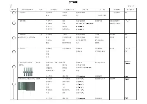
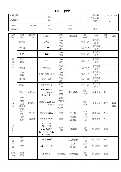
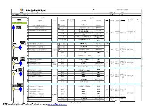
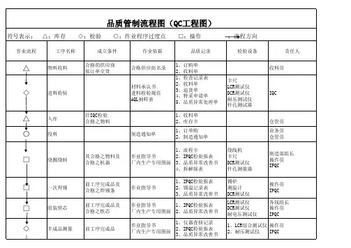
文件編號:頁次:1/5工程名称及使用材料設 備管 理 項 目品 質 確 認 方 法管理水準記 錄標準規格1、交貨點收品名規格訂購單每箱/每包檢查依訂購單倉管數量送貨單每批送貨單上簽名2、進料檢驗外箱標示目視每箱/每包檢查進料驗收單依進料檢驗標準IQC 檢驗員產品外觀目視MIL-STD-105E II AQL 0.015免檢料品一覽表產品尺寸遊尺規C=0 AQL 4.0產品特性依规格标准C=0 AQL 4.03、倉儲作業叉車品名規格入庫單每箱/每包檢查入庫單依訂購單倉管(入库,备料,发料,仓库整理)數量批次單/領料單每箱/每包檢查管制卡領料單生管先進先出目視依月份標簽管理實物進出帳本盤點帳與實物查對每月盤點表4、容量設計箔種確認化成箔檢查表每箱檢查箔出廠傳票規格書工程主管比容每箱檢查正箔領料計劃表品管箔寬箔長5、裁切(阳极箔,阴极箔,裁切機外觀、規格、批號、箔種目視每箱檢查裁切首件记录表裁切技术员&IPQC电解纸)寬度遊尺規首件:每片測量切邊毛刺顯微鏡首件:每片毛刺<0.015mm 捲邊突起過大目視每卷以上各项测试,目视巡检:5PCS/2H 巡檢記錄表IPQC6.釘接(阳极箔,阴极箔,导针)釘接機導針位置卡尺/显微镜首件n=1(+ -)釘接首件记录表製造標準釘接組長&IPQC擠壓厚度厚度分厘表首件n=1(+ -)長度钢尺首件n=1(+ -)宽度卡尺首件n=1(+ -)钉接阻抗阻抗测试仪首件n=1(+ -)外观目視首件n=1(+ -)以上各项测试,目视巡检:5PCS/2H 巡檢記錄表IPQCQC工程圖工程流程異常處理者456123頁次:2/5工 程 名設 備管 理 項 目品質確認方法管理水準記 錄標準規格7、捲繞(阳极箔,阴极箔,捲繞機導針間隔(PITCH)遊尺規首件 n=1捲繞首件记录表製造標準捲繞組長*IPQC电解纸)素子外徑遊尺規首件 n=1素子长度遊尺規首件 n=1拉力治具鋁箔與導針間之拉力治具/法碼首件 n=1拉力測試作業標準铝箔,电解纸长度钢尺首件 n=1铝箔,电解纸宽度遊尺規首件 n=1素子外觀目視首件 n=1以上各项测试,目视5PCS/2H 巡檢一次巡检记录表IPQC 8、素子外检外观目視100%生产日报表样品及限度样品擔當者&IPQC短路测试短路治具测试100%9、電解液調合調合釜机密机密机密電解液測試表机密電解液配制者( 嚴禁參閱流出 )(嚴禁參閱流出)10、烘烤,含浸,脱干.烘烤箱时间,温度目视6Φ(含)以上所有素子烘烤/含浸記錄表SOP 含浸技术员&IPQC(电解液,素子)含浸機真空度+時間目视每次烘烤/含浸記錄表SOP含浸技术员&IPQC加壓度+時間目视每次脫水機時間用手轻压素了顶部,每次工程部流程单含浸技术员&IPQC无电解液溢出即可以上各项目视巡检:2H 巡檢一次巡检记录表IPQC11、組立(素子,铝壳,胶盖)11.1.套铝壳素子规格目视每包製造標準組立組長&IPQC鋁殼規格规格标示每包外观目视作业员100%自主检查生产日报表組立組長&IPQC11.2.套胶盖膠蓋規格规格标示每包生产日报表組立組長&IPQC11.3.胶盖定位定位治具定位深度卡尺测量首件 n=5膠蓋定位首件記錄表組立組長&IPQCCamion工程流程異常處理者111078911.4.封口封口机外径卡尺测量首件 n=1封口首件记录表組立組長&IPQC长度卡尺测量首件 n=1束腰大小卡尺测量首件 n=1束腰位置卡尺测量首件 n=1P距卡尺测量首件 n=1硅油测试槽气密性硅油测试槽首件 n=3氣密性試驗程序拉力治具导针拉力拉力治具/法码首件 n=3拉力试验程序外观目视首件 n=1以上各项目视,测量.巡检:5PCS/2H 巡檢記錄表IPQC12 裸品清洗装水桶清洁目视依SOP 作业烘烤箱/脱水机时间,温度目视每批裸品清洗记录表无污物,无水份.清洗作业员13、排串/老化电木治具短路短路测试治具100%检测生產日報表无短路老化機老化電壓、電流電壓表設定值100%充电記錄表製造標準老化組長&IPQC老化溫度溫度設定100%老化時間計時器100%以上各项目视,测量巡检:5架/2H 巡檢記錄表IPQC14、裸品外檢外觀目視100%全數檢查生產日報表外觀限度样品后工程組長&IPQC 外觀目视巡检:5PCS/2H 巡檢記錄表IPQC15、套管套管機容量、電壓標示目視每批 n=1套管首件記錄表製造標準后工程組長&IPQC極性標示目視100%自主检查裸品外觀目視100%自主检查印字機D/C 印字是否清晰目視每批 n=1以上各项目视巡检:5PCS/2H 巡檢記錄表IPQC16、特性檢驗自動檢驗機容量自動機設定值100%測試生產日報表製造標準后工程組長&IPQC損失(tanδ)自動機設定值100%測試漏電流自動機設定值100%測試耐電壓自動機設定值100%測試以上各项自動機設定值巡检:10PCS/2H 巡檢記錄表IPQC硅油测试槽气密性硅油测试槽巡检:3PCS/2H 氣密性試驗程序拉力治具导针拉力拉力治具/法码巡检:3PCS/2H拉力试验程序121316141517、成品外觀檢查产品底部外观目視100%檢查生产日报表标准样品及限度样品后工程組長&IPQC产品顶部外观目視100%檢查产品侧面外观目視100%檢查外观目視巡检:5PCS/2H 巡檢記錄表IPQC18、切脚成型切脚成型机外观目視每批開始時切脚成型首件记录表規格書后工程組長&IPQC尺寸卡尺测量首件n=5作业标准成型方向目視100%以上各项目視,测试巡检:5PCS/2H 巡檢記錄表IPQC19、外观产品底部外观目視100%檢查包裝卡标准样品及限度样品后工程組長&IPQC产品顶部外观目視100%檢查产品侧面外观目視100%檢查以上各项目視巡检:5PCS/2H 巡檢記錄表IPQC 20、特性测试容量测试机容量,损失测试100%测试生产日报表规格书&作业标准擋當者以上各项测试巡检:10PCS/2H 巡檢記錄表IPQC 21、包裝包裝材料確認核對每批開始時包裝卡規格書擋當者標示確認核對每袋/每盒包裝規格數量目視/天秤每盒,每箱极反,极偏目視100%检查以上各項目視巡检:5PCS/2H 巡檢記錄表IPQC 22.品管抽檢容量測試機容量,损失角测试每批抽驗 5%成品檢驗報告製造標準OQC 漏電流測試機漏电流測試每批抽驗 5%規格書品管主管游標卡尺外径,长度,P 距測試每批抽驗10PCS生产主管17222120181923.入库叉车品名规格确认目视每箱入仓单仓管员数量确认目视每箱24、出貨檢查目視外箱标示內容確認每箱確認出貨檢驗報告规格书生产主管容量測試機容量 損失角测试C=0 AQL 4.0出货通知单FQC 漏電流測試機漏電測試C=0 AQL 4.0成品规格尺寸一览表品管主管游標卡尺製品尺寸遊尺規C=0 AQL 4.0外觀目視MIL-STD-105E II AQL 0.025限度样品25.客戶反饋客戶投訴依實據內容每次製造標準品管課客戶建議規格書生產部客戶稽核工程課2005.12.03修定日期:2012/6/19版 次:制定單位:品管課核準:確認:制 定:制定日期:客訴回復(依客戶要求格式)矯正與預防措施報告242523。
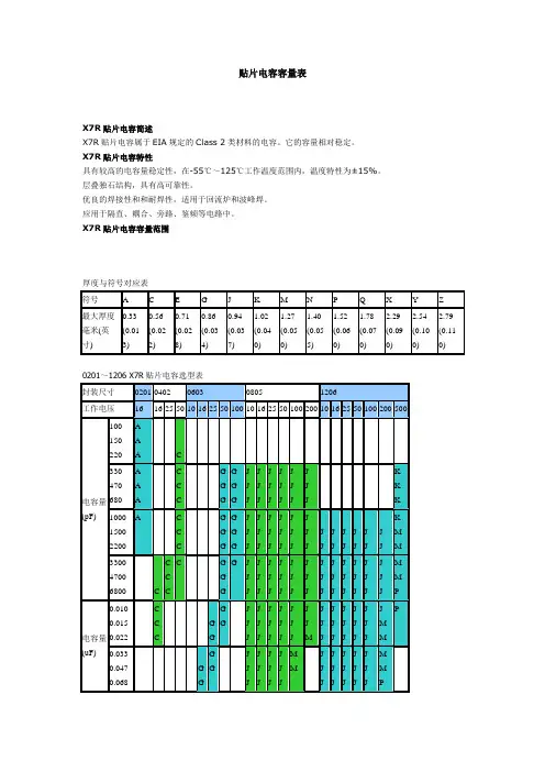
贴片电容容量表X7R贴片电容简述X7R贴片电容属于EIA规定的Class 2类材料的电容。
它的容量相对稳定。
X7R贴片电容特性具有较高的电容量稳定性,在-55℃~125℃工作温度范围内,温度特性为±15%。
层叠独石结构,具有高可靠性。
优良的焊接性和和耐焊性,适用于回流炉和波峰焊。
应用于隔直、耦合、旁路、鉴频等电路中。
X7R贴片电容容量范围厚度与符号对应表0201~1206 X7R贴片电容选型表1210~2225 X7R贴片电容选型表NPO COG 贴片电容容量规格表默认分类 2009-07-15 16:28 阅读354 评论1字号:大大中中小小NPO(COG)贴片电容属于Class 1温度补偿型电容。
它的容量稳定,几乎不随温度、电压、时间的变化而变化。
尤其适用于高频电子电路。
具有最高的电容量稳定性,在-55℃~125℃工作温度范围内,温度特性为:0±30ppm/℃(COG)、0±60ppm/℃(COH)。
层叠独石结构,具有高可靠性。
优良的焊接性和和耐焊性,适用于回流炉和波峰焊。
应用于各种高频电路,如:振荡、计时电路等。
我们把用来制造片式多层瓷介电容(MLCC)的陶瓷叫电容器瓷。
这里所说的瓷介就是用电容器瓷制成的陶瓷介质。
大家知道,陶瓷是一类质硬、性脆的无机烧结体。
就其显微结构而论,大都具有多晶多相结构。
其性能往往决定于其成份和结构。
当配方确定之后,能否达到预期的效果,关键取决于制造陶瓷粉料的工艺。
按其用途可以分为三类:①高频热补偿电容器瓷(UJ、SL);②高频热稳定电容器瓷(NPO);③低频高介电容器瓷(X7R、Y5V、Z5U)。
按温度系数分可以分为两类:①负温度系数电容器瓷(即高频热补偿电容器瓷);②正温度系数电容器瓷(即平时我们常说的COG、X7R、Y5V瓷料)。
按工作频率可以分为三类:低频、高频、微波介质。
高频热补偿、热稳定电容器瓷是专供Ⅰ类瓷介电容器作介质用,其瓷料主要成分是MgTiO3、CaTiO3、SrTiO3和TiO2再加入适量的稀土类氧化物等配制而成。
产品规格书产品名称: 超级电容器产品型号: WTC5V51F5Z-0720C变更履历表版本修订人变更内容变更日期R21.1 任倩倩1、增加了最大峰值电流(1s) 2021.09.24目录质量声明 (4)1. 适用范围 (5)2. 标准测试条件 (5)3. 一般特性 (5)4. 包装方式 (5)5. 环境性能指标 (6)6. 产品尺寸及外形 (6)7. 命名规则 (7)8. 测试方法 (7)9. 注意事项和使用指导 (9)10. 免责声明 (11)质量声明正确的使用和维护保养才能确保您的电容(或电容系统)长期可靠稳定地运行。
⚫收到产品后,请检查包装是否完好,若包装破损,可能导致产品损坏。
若有损坏,请于五个工作日内联系我司售后或销售人员。
⚫凡不按本说明书规定进行使用或维护保养者,视同放弃保修权利,上海闻亭实业有限公司及其服务站有权不再予以保修,对由此而产生的一切损失也不予以赔偿,但可以根据情况提供相应的有偿服务。
⚫贵司在收到产品及产品说明书后,请于7日内回复。
7日内未回复,我司将视客户承认此产品及产品说明书符合贵司要求。
公司信息地址:上海市黄浦区广西北路528号电话:+86-021-********邮编:200001邮箱:******************网址:1. 适用范围本产品规格书描述了上海闻亭实业有限公司(以下简称闻亭信息)生产的圆柱式超级电容器的产品性能指标。
2. 标准测试条件一般情况下,在标准大气压下,温度15~35 o C,相对湿度在25%~75%条件下进行测试;测试前样品应该在测试温度下放置12 h以上,本规格书的测试条件为标准大气压,温度为25±2 o C,相对湿度为60±15%。
3. 一般特性测试项目规格/条件1 型号WTC5V51F5Z-0720C2 额定容量 1.5 F3 容量偏差-20 % ~ + 80 %4 工作电压 5.5V5 浪涌电压 6.0 V6 标称内阻交流阻抗20 Ω直流阻抗30 Ω7 产品重量8.5±0.05g8 最大峰值电流(1 s) 90mA9 漏电流(24 h) ≤0.02mA10 工作温度-40 ~ 70 o C11 储存温度-40 ~ 85 o C12 循环寿命25ºC,额定电压到半额定电压间循环充放电50万次,|∆C/C|≤30%,ESR≤4倍初始值(25ºC)4. 包装方式产品型号包装数量(只)包装箱尺寸(L×W×H, mm)整箱重量(Kg)每外箱每吸塑盘每内箱每外箱每吸塑盘每内箱WTC5V51F5Z-0720C80 400 1600 331×228×117 485×355×265 16±15. 环境性能指标项目规格/条件1 温度特性+70 o C时|∆C/C|≤30 %,ESR≤规定值(25 o C)-25 o C时|∆C/C|≤50 %,ESR≤4倍初始值(25 o C)2 高温负荷特性+70 o C ± 2加额定电压,1000h后,|∆C/C|≤30%,ESR≤4倍规定值。

Eaton 281307Eaton Moeller series NZM - Molded Case Circuit Breaker. Circuit-breaker, 3p, 125A, H2-M125Allgemeine spezifikationEaton Moeller series NZM molded case circuit breaker thermo-magnetic281307149 mm184 mm 105 mm 2.334 kg RoHS conform IEC IEC/EN 609474015082813079NZMH2-M125Product NameCatalog NumberProduct Length/Depth Product Height Product Width Product Weight Compliances Certifications EANModel Code125 AIs the panel builder's responsibility. The specifications for the switchgear must be observed.5 kA130 kAMeets the product standard's requirements.Is the panel builder's responsibility. The specifications for the switchgear must be observed.Built-in device fixed built-in techniqueFixed125 ADoes not apply, since the entire switchgear needs to be evaluated.Min. 2 segments of 9 mm x 0.8 mm at box terminalMax. 8 segments of 24 mm x 1 mm (2x) at box terminal Max. 10 segments of 16 mm x 0.8 mm at box terminalMax. 10 segments of 24 mm x 0.8 mm at rear-side connection (punched)Min. 2 segements of 16 mm x 0.8 mm at rear-side connection (punched)Rocker leverMeets the product standard's requirements.40 °C eaton-circuit-breaker-let-through-current-nzm-mccb-characteristic-curve-005.epseaton-circuit-breaker-characteristic-power-defense-mccb-characteristic-curve-037.epsMH2-M125il01206006z2015_11.pdfDas neue digitale NZM-Sortiment - In Kurze verfugbar DE Vorstellung des neuen digitalen Leistungsschalter NZMDA-CD-nzm2_3pDA-CS-nzm2_3peaton-manual-motor-starters-starter-msc-r-reversing-starter-wiring-diagram.epseaton-manual-motor-starters-starter-nzm-mccb-wiring-diagram.epseaton-nzm-technical-information-sheeteaton-circuit-breaker-nzm-mccb-dimensions-019.epsRated operational current for specified heat dissipation (In) 10.11 Short-circuit ratingRated short-circuit breaking capacity Ics (IEC/EN 60947) at 690 V, 50/60 HzRated short-circuit breaking capacity Icu (IEC/EN 60947) at 400/415 V, 50/60 Hz10.4 Clearances and creepage distances10.12 Electromagnetic compatibilityMounting MethodAmperage Rating10.2.5 LiftingTerminal capacity (copper strip)Handle type10.2.3.1 Verification of thermal stability of enclosuresAmbient storage temperature - min Characteristic curveeCAD model Installationsanleitung Installationsvideos mCAD modelSchaltpläneTechnische Datenblätter ZeichnungenFitted with:Thermal protectionProtection against direct contactFinger and back-of-hand proof to VDE 0106 part 100Terminal capacity (copper busbar)Max. 24 mm x 8 mm direct at switch rear-side connectionMin. 16 mm x 5 mm direct at switch rear-side connectionM8 at rear-side screw connection10.8 Connections for external conductorsIs the panel builder's responsibility.Special featuresMaximum back-up fuse, if the expected short-circuit currents at the installation location exceed the switching capacity of the circuit breaker (Rated short-circuit breaking capacity Icn) Rated current = rated uninterrupted current: 125 A Tripping class 10 A IEC/EN 60947-4-1, IEC/EN 60947-2 The circuit-breaker fulfills all requirements for AC-3 switching category.Ambient operating temperature - max70 °CClimatic proofingDamp heat, cyclic, to IEC 60068-2-30Damp heat, constant, to IEC 60068-2-78Terminal capacity (aluminum stranded conductor/cable)25 mm² - 50 mm² (1x) direct at switch rear-side connection25 mm² - 50 mm² (2x) direct at switch rear-side connection25 mm² - 185 mm² (1x) at tunnel terminalTerminal capacity (copper stranded conductor/cable)25 mm² - 70 mm² (2x) at box terminal25 mm² - 185 mm² (1x) direct at switch rear-side connection25 mm² - 185 mm² (1x) at box terminal25 mm² - 185 mm² (1x) at 1-hole tunnel terminal25 mm² - 70 mm² (2x) direct at switch rear-side connectionLifespan, electrical6500 operations at 400 V AC-310000 operations at 400 V AC-17500 operations at 690 V AC-16500 operations at 415 V AC-35000 operations at 690 V AC-310000 operations at 415 V AC-1Electrical connection type of main circuitScrew connectionShort-circuit total breaktime< 10 msRated impulse withstand voltage (Uimp) at main contacts8000 VRated short-circuit breaking capacity Ics (IEC/EN 60947) at 400/415 V, 50/60 Hz130 kA10.9.3 Impulse withstand voltageIs the panel builder's responsibility.Utilization categoryA (IEC/EN 60947-2)Number of polesThree-poleAmbient operating temperature - min-25 °C10.6 Incorporation of switching devices and componentsDoes not apply, since the entire switchgear needs to be evaluated.10.5 Protection against electric shockDoes not apply, since the entire switchgear needs to be evaluated.Terminal capacity (control cable)0.75 mm² - 2.5 mm² (1x)0.75 mm² - 1.5 mm² (2x)Equipment heat dissipation, current-dependent27.61 WInstantaneous current setting (Ii) - min1000 A10.13 Mechanical functionThe device meets the requirements, provided the information in the instruction leaflet (IL) is observed.10.2.6 Mechanical impactDoes not apply, since the entire switchgear needs to be evaluated.10.9.4 Testing of enclosures made of insulating materialIs the panel builder's responsibility.Rated operational current99 A (400 V AC-3)Rated short-circuit breaking capacity Ics (IEC/EN 60947) at 230 V, 50/60 Hz150 kAApplicationUse in unearthed supply systems at 690 V10.3 Degree of protection of assembliesDoes not apply, since the entire switchgear needs to be evaluated.Rated short-circuit making capacity Icm at 240 V, 50/60 Hz330 kARated short-circuit breaking capacity Ics (IEC/EN 60947) at 440 V, 50/60 Hz130 kADegree of protection (IP), front sideIP40 (with insulating surround)IP66 (with door coupling rotary handle)Rated short-circuit making capacity Icm at 525 V, 50/60 Hz105 kARated short-circuit making capacity Icm at 690 V, 50/60 Hz40 kAInstantaneous current setting (Ii) - max1750 AOverload current setting (Ir) - min100 A10.2.3.2 Verification of resistance of insulating materials to normal heatMeets the product standard's requirements.10.2.3.3 Resist. of insul. mat. to abnormal heat/fire by internal elect. effectsMeets the product standard's requirements.Lifespan, mechanical20000 operationsOverload current setting (Ir) - max125 AVoltage rating690 V - 690 VTerminal capacity (copper solid conductor/cable)10 mm² - 16 mm² (1x) at box terminal6 mm² - 16 mm² (2x) direct at switch rear-side connection6 mm² - 16 mm² (2x) at box terminal10 mm² - 16 mm² (1x) direct at switch rear-side connection16 mm² (1x) at tunnel terminalDegree of protection (terminations)IP10 (tunnel terminal)IP00 (terminations, phase isolator and strip terminal)10.9.2 Power-frequency electric strengthIs the panel builder's responsibility.Short-circuit release non-delayed setting - min1000 ADegree of protectionIP20IP20 (basic degree of protection, in the operating controls area)Overvoltage categoryIIIRated short-time withstand current (t = 1 s)1.9 kARated impulse withstand voltage (Uimp) at auxiliary contacts 6000 VTerminal capacity (aluminum solid conductor/cable)10 mm² - 16 mm² (2x) direct at switch rear-side connection16 mm² (1x) at tunnel terminal10 mm² - 16 mm² (1x) direct at switch rear-side connectionSwitch off techniqueThermomagneticRated short-time withstand current (t = 0.3 s)1.9 kAAmbient storage temperature - max70 °CRated short-circuit breaking capacity Ics (IEC/EN 60947) at 525 V, 50/60 Hz37.5 kAOptional terminalsBox terminal. Connection on rear. Tunnel terminalRelease systemThermomagnetic releasePollution degree310.7 Internal electrical circuits and connectionsIs the panel builder's responsibility.Rated operating power at AC-3, 230 V37 kW10.10 Temperature riseThe panel builder is responsible for the temperature rise calculation. Eaton will provide heat dissipation data for the devices.FunctionsMotor protectionShort-circuit release non-delayed setting - max1750 AStandard terminalsScrew terminalRated short-circuit making capacity Icm at 400/415 V, 50/60 Hz 330 kARated operating power at AC-3, 400 V55 kWTypeCircuit breaker10.2.2 Corrosion resistanceMeets the product standard's requirements.10.2.4 Resistance to ultra-violet (UV) radiationMeets the product standard's requirements.10.2.7 InscriptionsMeets the product standard's requirements.Rated short-circuit making capacity Icm at 440 V, 50/60 Hz 286 kAIsolation500 V AC (between auxiliary contacts and main contacts)300 V AC (between the auxiliary contacts)Number of operations per hour - max120Circuit breaker frame typeNZM2Direction of incoming supplyAs requiredShock resistance20 g (half-sinusoidal shock 20 ms)Eaton Konzern plc Eaton-Haus30 Pembroke-Straße Dublin 4, Irland © 2023 Eaton. Alle Rechte vorbehalten. Eaton ist eine eingetrageneMarke.Alle anderen Warenzeichen sindEigentum ihrer jeweiligenBesitzer./socialmedia1000 VRated insulation voltage (Ui)。
表 号:P8241-2-编制部门:品质部 检验日期: 年 月 日
生产日期: 年 月 日
北京时间
环境温度
相对湿度
表 号:P8241-2-编制部门:品质部 检验日期: 年 月 日
生产日期: 年 月 日
北京时间
环境温度
相对湿度
测试条件
测试条件说明:√表示合格
运行电流(A)试验结果
广州万宝集团民权电器有限公司
产品型号产品安全、电气性能测试记录表
产品编号试验台号防触电保护接地电阻(Ω)广州万宝集团民权电器有限公司
产品安全、电气性能测试记录表
确认人:
质检员:
泄漏电流(mA)绝缘电阻(M Ω)
电气强度输入功率(W)审核人:
防触电保护测试条件接地电阻(Ω)说明:√表示合格泄漏电流(mA)产品型号测试条件产品编号试验台号试验结果
质检员:
绝缘电阻(M Ω)
审核人:
电气强度输入功率(W)确认人:
运行电流(A)。
MT-5110 3 1/2 Capacitance MeterUser’s Manual1st Edition, 20121. FEATURES◇Easy and correct readout.◇High measuring accuracy.◇Measurements are possible even under a strong magnetic field.◇LSI-circuit provides high reliability and durability.◇Input overload protection is provided.◇LCD display for clear readout even in bright ambient light conditions.◇Light-weight and compact construction for easy operation.◇Low battery condition is indicated on the LCD display.◇Low power consumption.2. SPECIFICATIONS2-1.GENERAL SPECIFICATIONS∙Display: LCD (Liquid Crystal Display) Max. Indication 1999.∙ Measurement: C (Capacitance)∙Range: single 9 position, whole range value (from 0.1pF to 20000uF)∙ Zero Adjustment :Manual (range:±20pF)∙Calibrate Adjustment: Have two internal adjustments.∙Over-input: Display shows “1”.∙Backlight Function: it went out by itself within 8 seconds.∙ Sampling Time: 0~5second∙ Operating Temp: 0℃ to 40℃.∙Operating Humidity: 80% MAX.R.H.∙Power Supply: Single, standard 9 volt battery. NEDA1604IEC6F22∙Typical consumption current: 3~4mA∙ Standard Accessories: Test alligator clips (red & black)…1 pair.Test leads (red & black)………….1 pair.Test socket …………………… … 1 pc ∙Instruction manual………………………….………… ……..1 pc.2-2. ELECTRICAL SPECIFICATIONAccuracy is ±(percentage of reading + number of digit) at 23±5℃,<80%RH.Range Accuracy ResolutionTest Frequency Max indication value 200pF ±(0.5%+7) 0.1pF 800Hz 199.9pF2nF 1pF 800Hz 1.999nF 20nF 10pF 800Hz19.99nF 200nF 100pF 800Hz 199.9nF 2uF 1000pF 800Hz 1.999uF20uF 0.01uF 80Hz 19.99uF 200uF ±(0.5%+5) 0.1uF 8Hz 199.9uF 2000uF ±(2%+5) 1uF 8Hz 1999uF20000uF ±(3%+10) 10uF 8Hz 1999(×10)uFpF= Pico Farad(10-12F ),nF= nan Farad(10-9F). uF= micro Farad(10-6F) Excitative voltage: Max.2.8VrmsOverload Rating: Protection by a 0.1A/250V fuse.3. OPERATION PANEL1. Model Number2. LCD display: display the test value and unit.3. Backlight key: press the button lightly; itwas turning off by itself about 8 seconds.4. Capacitance “+”input terminal.5. Capacitance”-”input terminal.6. Function Selector: It is used for power onand changes the range of function.7. Zero knob: Knob to zero when test lowcapacitance.4. CONSIDERATION OF MEASUREMENT(1) This C METER is intended for measuring the capacitance value ofa capacitor. It is not intended for determining the “Q” factor forabove reactive components. Misleading readings may be obtainedif the measurement of capacitance of a resistor is attempted.(2) When measuring components within circuit that circuit must beswitched off and de-energized before connecting the test leads.(3) Do not damage (black & red) test leads, if any worn please change(4) Instruments used in dusty environments should be stripped andcleaned periodically.(5) Do not leave the instrument exposed to direct heat from the sun forlong periods.(6) Before removing the battery and fuse compartment cover, ensurethat the instrument is disconnected with any circuit and the powerswitch is in the off position.(7) For all measurements, should connect BLACK test lead into “-”terminal and RED test lead into “+” terminal.5. CAPACITANCE(C) MEASURING PROCEDURE(1) Select the range selector for the maximum expected capacitance.(2) The power will on when the selector switch away from OFFposition.(3) Check "0" indication: If test range is 200pF, 2nF, 20nF, shouldcheck "0" indication before test.(4) Observe polarity when connecting polarized capacitors.(5) Full discharge any capacitors.(6) Connect the alligator clips to the capacitors leads.(7) Read the display. The value is direct reading in the electrical unit(pF, nF, uF) indicated at the selected range switch. If display show“1”, It indicate on Out-of-Range measurement. If the displayindicates one or more leading zeros, shift to the next lower rangescale to improve the resolution of the measurement.NOTE:(a) If the capacitance value is unmarked, start with the 200pF range andkeep increasing until the over-range indication goes off and areading is obtained.(b) A shorted capacitor will read over-range on all ranges. A capacitancewith low voltage leakage will read over range, or a much highervalue than normal. An open capacitor will read zero on all ranges(possibly a few pF on 200pF range, due to stray capacitance of theinstrument).(c) Measure of very low capacitance should be performed usingextremely short leads in order to avoid introducing any strayinductance.(d) When using the optioned test leads, remember that the leadsintroduce a measurable capacitance to the measurement. As a firstapproximation, the test lead capacitance may be measured byopening the leads at the trips, recording the open circuit value andsubtracting that value.(e) Capacitors, especially electrolytic, often have notoriously widetolerances. Do not be surprised if the measured value is greater than the value marked on the capacitor, unless it is a close tolerance type.However, values are seldom drastically below the rated value.(f) If changing range, measured value will be changed; leakage-voltagecapacitors will be checked also. Leakage-resistance will bedecreased in lower range.6. MAINTENANCE1) 9-Volt battery replacementa. Ensure the instrument is not connected to any external circuit. Setthe selector switch to OFF position and remove the test leads from terminals.b. Remove the screw on the bottom case and lift the bottom case.c. Remove the spent battery and replace it with a battery of the sametype.2) Fuse replacementa. Ensure the instrument is not connected to any external circuit. Setthe selector switch to OFF position and remove the test leads from terminals.b. Remove the screw on the bottom case and lift the bottom case.c. Replace the fuse with the same type and rating: 5×20mm,100mA/250V, fast-blow fuse or as the replacements.The specifications are subject to change without notice.The content of this manual is regarded as correct, error or omits Pls.contact with factory.We hereby will not be responsible for the accident and damagecaused by improper operation.The function stated for this User Manual cannot be the reason ofspecial usage.MT-51103 1/2數位電容錶1. 特色◇測量準確, 讀數方便◇測量精度高◇在幹擾的磁場下依然可以測量◇LSI電路提供高可靠性和耐久性◇提供輸入過載保護◇即使在明亮室內光線狀況下, LCD清楚顯示測量結果◇結構設計容易操作使用◇若工作電池電壓低, LCD上會顯示低電壓符號提醒◇整機低功耗2. 說明2-1.一般說明⏹顯示︰LCD(液晶顯示螢幕) 最大讀值1999⏹測量︰C(僅電容量)⏹範圍︰9個檔位, 全範圍值從0.1pF to 20000uF⏹歸零調整︰手動(範圍︰大約 ±20pF)⏹校驗調整︰內含2個調整裝置⏹輸入超過︰螢幕顯示 “1”⏹背光功能︰8秒內⏹採樣時間︰0 ~5second⏹操作溫度︰0 ℃~40 ℃.最大濕度:80%.R.H.⏹電源︰1個標準的9伏特電池。