Slow cross-symmetry phase relaxation in complex collisions
- 格式:pdf
- 大小:241.16 KB
- 文档页数:10
材料科学基础专业词汇:第一章晶体结构原子质量单位Atomic mass unit (amu) 原子数Atomic number原子量Atomic weight 波尔原子模型Bohr atomic model键能Bonding energy 库仑力Coulombic force共价键Covalent bond 分子的构型molecular configuration 电子构型electronic configuration 负电的Electronegative正电的Electropositive 基态Ground state氢键Hydrogen bond 离子键Ionic bond同位素Isotope 金属键Metallic bond摩尔Mole泡利不相容原理 Pauli exclusion principle 元素周期表Periodic table原子atom 分子molecule分子量molecule weight 极性分子Polar molecule量子数quantum number 价电子valence electron范德华键van der waals bond 电子轨道electron orbitals点群point group 对称要素symmetry elements各向异性anisotropy 原子堆积因数Atomic packing factor(APF)体心立方结构body-centered cubic (BCC) 面心立方结构face-centered cubic (FCC) 布拉格定律bragg’s law 配位数coordination number晶体结构crystal structure 晶系crystal system晶体的crystalline 衍射diffraction中子衍射neutron diffraction 电子衍射electron diffraction晶界grain boundary 六方密堆积hexagonal close-packed(HCP)鲍林规则Pauling’s rules NaCl型结构NaCl-type structure CsCl型结构Caesium Chloride structure 闪锌矿型结构Blende-type structure纤锌矿型结构Wurtzite structure 金红石型结构Rutile structure萤石型结构Fluorite structure 钙钛矿型结构Perovskite-type structure 尖晶石型结构Spinel-type structure 硅酸盐结构Structure of silicates岛状结构Island structure 链状结构Chain structure层状结构Layer structure 架状结构Framework structure滑石talc 叶蜡石pyrophyllite高岭石kaolinite 石英quartz长石feldspar 美橄榄石forsterite各向同性的isotropic 各向异性的anisotropy晶格lattice 晶格参数lattice parameters密勒指数miller indices 非结晶的noncrystalline多晶的polycrystalline 多晶形polymorphism单晶single crystal 晶胞unit cell电位electron states (化合)价valence电子electrons 共价键covalent bonding金属键metallic bonding 离子键Ionic bonding极性分子polar molecules 原子面密度atomic planar density衍射角diffraction angle 合金alloy粒度,晶粒大小grain size 显微结构microstructure显微照相photomicrograph 扫描电子显微镜scanning electronmicroscope (SEM)重量百分数weight percent 透射电子显微镜 transmission electronmicroscope (TEM)四方的tetragonal 单斜的monoclinic配位数coordination number材料科学基础专业词汇:第二章晶体结构缺陷缺陷defect, imperfection 点缺陷point defect线缺陷line defect, dislocation 面缺陷interface defect体缺陷volume defect 位错排列dislocation arrangement位错线dislocation line 刃位错edge dislocation螺位错screw dislocation 混合位错mixed dislocation晶界grain boundaries 大角度晶界high-angle grainboundaries 小角度晶界tilt boundary, 孪晶界twin boundaries位错阵列dislocation array 位错气团dislocation atmosphere位错轴dislocation axis 位错胞dislocation cell位错爬移dislocation climb 位错聚结dislocation coalescence位错滑移dislocation slip 位错核心能量dislocation core energy位错裂纹dislocation crack 位错阻尼dislocation damping位错密度dislocation density 原子错位substitution of a wrongatom间隙原子interstitial atom 晶格空位vacant lattice sites间隙位置interstitial sites 杂质impurities弗伦克尔缺陷Frenkel disorder 肖脱基缺陷Schottky disorder主晶相the host lattice 错位原子misplaced atoms缔合中心Associated Centers. 自由电子Free Electrons电子空穴Electron Holes 伯格斯矢量Burgers克罗各-明克符号K roger Vink notation 中性原子neutral atom材料科学基础专业词汇:第二章晶体结构缺陷-固溶体固溶体solid solution 固溶度solid solubility化合物compound 间隙固溶体interstitial solid solution置换固溶体substitutional solid solution 金属间化合物intermetallics不混溶固溶体immiscible solid solution 转熔型固溶体peritectic solid solution有序固溶体ordered solid solution 无序固溶体disordered solid solution 固溶强化solid solution strengthening 取代型固溶体Substitutional solidsolutions过饱和固溶体supersaturated solid solution 非化学计量化合物Nonstoichiometric compound材料科学基础专业词汇:第三章熔体结构熔体结构structure of melt 过冷液体supercooling melt玻璃态vitreous state 软化温度softening temperature粘度viscosity 表面张力Surface tension介稳态过渡相metastable phase 组织constitution淬火quenching 退火的softened玻璃分相phase separation in glasses 体积收缩volume shrinkage材料科学基础专业词汇:第四章固体的表面与界面表面surface 界面interface同相界面homophase boundary 异相界面heterophase boundary晶界grain boundary 表面能surface energy小角度晶界low angle grain boundary 大角度晶界high angle grain boundary 共格孪晶界coherent twin boundary 晶界迁移grain boundary migration 错配度mismatch 驰豫relaxation重构reconstuction 表面吸附surface adsorption表面能surface energy 倾转晶界titlt grain boundary扭转晶界twist grain boundary 倒易密度reciprocal density共格界面coherent boundary 半共格界面semi-coherent boundary 非共格界面noncoherent boundary 界面能interfacial free energy应变能strain energy 晶体学取向关系crystallographicorientation惯习面habit plane材料科学基础专业词汇:第五章相图相图phase diagrams 相phase组分component 组元compoonent相律Phase rule 投影图Projection drawing浓度三角形Concentration triangle 冷却曲线Cooling curve成分composition 自由度freedom相平衡phase equilibrium 化学势chemical potential热力学thermodynamics 相律phase rule吉布斯相律Gibbs phase rule 自由能free energy吉布斯自由能Gibbs free energy 吉布斯混合能Gibbs energy of mixing 吉布斯熵Gibbs entropy 吉布斯函数Gibbs function热力学函数thermodynamics function 热分析thermal analysis过冷supercooling 过冷度degree of supercooling杠杆定律lever rule 相界phase boundary相界线phase boundary line 相界交联phase boundarycrosslinking共轭线conjugate lines 相界有限交联phase boundarycrosslinking相界反应phase boundary reaction 相变phase change相组成phase composition 共格相phase-coherent金相相组织phase constentuent 相衬phase contrast相衬显微镜phase contrast microscope 相衬显微术phase contrastmicroscopy相分布phase distribution 相平衡常数phase equilibriumconstant相平衡图phase equilibrium diagram 相变滞后phase transition lag相分离phase segregation 相序phase order相稳定性phase stability 相态phase state相稳定区phase stabile range 相变温度phase transitiontemperature相变压力phase transition pressure 同质多晶转变polymorphictransformation同素异晶转变allotropic transformation 相平衡条件phase equilibriumconditions显微结构microstructures 低共熔体eutectoid不混溶性immiscibility材料科学基础专业词汇:第六章扩散活化能activation energy扩散通量diffusion flux浓度梯度concentration gradient菲克第一定律Fick’s first law菲克第二定律Fick’s second law相关因子correlation factor稳态扩散steady state diffusion非稳态扩散nonsteady-state diffusion 扩散系数diffusion coefficient跳动几率jump frequency填隙机制interstitalcy mechanism晶界扩散grain boundary diffusion 短路扩散short-circuit diffusion上坡扩散uphill diffusion下坡扩散Downhill diffusion互扩散系数Mutual diffusion渗碳剂carburizing浓度梯度concentration gradient 浓度分布曲线concentration profile扩散流量diffusion flux驱动力driving force间隙扩散interstitial diffusion自扩散self-diffusion表面扩散surface diffusion空位扩散vacancy diffusion扩散偶diffusion couple扩散方程diffusion equation扩散机理diffusion mechanism扩散特性diffusion property无规行走Random walk达肯方程Dark equation柯肯达尔效应Kirkendall equation本征热缺陷Intrinsic thermal defect本征扩散系数Intrinsic diffusion coefficient离子电导率Ion-conductivity空位机制Vacancy concentration材料科学基础专业词汇:第七章相变过冷supercooling 过冷度degree of supercooling 晶核nucleus 形核nucleation形核功nucleation energy 晶体长大crystal growth均匀形核homogeneous nucleation 非均匀形核heterogeneous nucleation形核率nucleation rate 长大速率growth rate 热力学函数thermodynamics function临界晶核critical nucleus 临界晶核半径critical nucleus radius枝晶偏析dendritic segregation 局部平衡localized equilibrium平衡分配系数equilibriumdistributioncoefficient有效分配系数effective distribution coefficient成分过冷constitutional supercooling 引领(领先)相leading phase共晶组织eutectic structure 层状共晶体lamellar eutectic伪共晶pseudoeutectic 离异共晶divorsed eutectic表面等轴晶区chill zone 柱状晶区columnar zone中心等轴晶区equiaxed crystal zone 定向凝固unidirectional solidification 急冷技术splatcooling 区域提纯zone refining单晶提拉法Czochralski method 晶界形核boundary nucleation位错形核dislocation nucleation 晶核长大nuclei growth斯宾那多分解spinodal decomposition有序无序转变disordered-order transition马氏体相变martensite phase transformation 马氏体martensite材料科学基础专业词汇:第八、九章固相反应和烧结固相反应solid state reaction 烧结sintering烧成fire 合金alloy再结晶Recrystallization 二次再结晶Secondary recrystallization 成核nucleation 结晶crystallization子晶,雏晶matted crystal 耔晶取向seed orientation异质核化heterogeneous nucleation 均匀化热处理homogenization heattreatment铁碳合金iron-carbon alloy 渗碳体cementite铁素体ferrite 奥氏体austenite共晶反应eutectic reaction 固溶处理solution heat treatment。
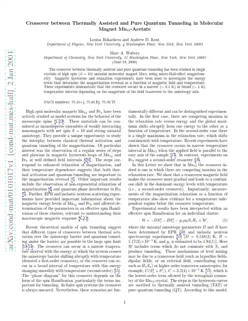
a r X i v :c o n d -m a t /0101017v 1 [c o n d -m a t .m e s -h a l l ] 2 J a n 2001Crossover between Thermally Assisted and Pure Quantum Tunneling in MolecularMagnet Mn 12-AcetateLouisa Bokacheva and Andrew D.KentDepartment of Physics,New York University,4Washington Place,New York,New York 10003Marc A.WaltersDepartment of Chemistry,New York University,31Washington Place,New York,New York 10003(June 19,2000)The crossover between thermally assisted and pure quantum tunneling has been studied in single crystals of high spin (S =10)uniaxial molecular magnet Mn 12using micro-Hall-effect magnetom-etry.Magnetic hysteresis and relaxation experiments have been used to investigate the energy levels that determine the magnetization reversal as a function of magnetic field and temperature.These experiments demonstrate that the crossover occurs in a narrow (∼0.1K)or broad (∼1K)temperature interval depending on the magnitude of the field transverse to the anisotropy axis.PACS numbers:75.45+j,75.60.Ej,75.50.TtHigh spin molecular magnets Mn 12and Fe 8have been actively studied as model systems for the behavior of the mesoscopic spins [1–12].These materials can be con-sidered as monodisperse ensembles of weakly interacting nanomagnets with net spin S =10and strong uniaxial anisotropy.They provide a unique opportunity to study the interplay between classical thermal activation and quantum tunneling of the magnetization.Of particular interest was the observation of a regular series of steps and plateaus in magnetic hysteresis loops of Mn 12and Fe 8at well defined field intervals [2,3].The steps cor-respond to enhanced relaxation of magnetization,and their temperature dependence suggests that both ther-mal activation and quantum tunneling are important to the magnetization reversal [5].Other important results include the observation of non-exponential relaxation of magnetization [3]and quantum phase interference in Fe 8[7].Further,EPR and inelastic neutron scattering exper-iments have provided important information about the magnetic energy levels of Mn 12and Fe 8and allowed de-termination of the parameters in an effective spin Hamil-tonian of these clusters,relevant to understanding their macroscopic magnetic response [8–12].Recent theoretical models of spin tunneling suggest that different types of crossovers between thermal acti-vation over the anisotropy barrier and quantum tunnel-ing under the barrier are possible in the large spin limit [13,14].The crossover can occur in a narrow tempera-ture interval with the energy at which the system crosses the anisotropy barrier shifting abruptly with temperature (denoted a first-order crossover),or the crossover can oc-cur in a broad interval of temperature with this energy changing smoothly with temperature (second-order)[15].The “phase diagram”for this crossover depends on the form of the spin Hamiltonian,particularly the terms im-portant for tunneling.In finite spin systems the crossover is always smeared.Nevertheless,these scenarios are fun-damentally different and can be distinguished experimen-tally.In the first case,there are competing maxima in the relaxation rate versus energy and the global maxi-mum shifts abruptly from one energy to the other as a function of temperature.In the second-order case there is a single maximum in the relaxation rate,which shifts continuously with temperature.Recent experiments have shown that the crossover occurs in narrow temperature interval in Mn 12when the applied field is parallel to the easy axis of the sample [17].In contrast,experiments on Fe 8suggest a second-order crossover [18].In this Letter we show that in Mn 12the crossover in-deed is one in which there are competing maxima in the relaxation rate.We show that a transverse magnetic field makes the crossover more gradual and leads to a continu-ous shift in the dominant energy levels with temperature (i.e.,a second-order crossover).Importantly,measure-ments of the magnetization relaxation as a function of temperature also show evidence for a temperature inde-pendent regime below the crossover temperature.Experimental results have been interpreted within an effective spin Hamiltonian for an individual cluster:H =−DS 2z −BS 4z −g z µB S z H z +H ′,(1)where the uniaxial anisotropy parameters D and B havebeen determined by EPR [10]and inelastic neutron spectroscopy experiments [11][D =0.548(3)K,B =1.17(2)×10−3K,and g z is estimated to be 1.94(1)].Here H ′includes terms which do not commute with S z and produce tunneling.These mechanisms of level mixing may be due to a transverse field (such as hyperfine fields,dipolar fields,or an external field,contributing terms such as H x S x )or higher order transverse anisotropies,forexample,C (S 4++S 4−),C =2.2(4)×10−5K [11],which is the lowest-order term allowed by the tetragonal symme-try of the Mn 12crystal.The steps in the hysteresis curves are ascribed to thermally assisted tunneling (TAT)or pure quantum tunneling (QT).According to this model,the magnetization relaxation occurs by tunneling from magnetic sublevels (m =10,9,8,...,−8,−9,−10),when two levels on the opposite sides of the barrier are brought close to resonance by the magnetic field.From the un-perturbed Hamiltonian (1)the longitudinal (z -axis)field at which the levels m esc and m ′become degenerate is:H (n,m esc )=nH 0{1+B/D [m 2esc +(m esc −n )2]}(2)where n =m esc +m ′is the step index describing the bias field and H 0=D/g z µB is a constant (0.42T).The transverse anisotropy does not significantly change the resonance fields,as we have checked by direct numerical diagonalization of the Hamiltonian (1).Note that larger magnetic field is necessary to bring lower lying sublevels into resonance.As the temperature decreases,the thermal population of the excited levels is reduced,and these states contribute less and less to the tunneling.Consequently,the steps in hysteresis curves shift to higher bias field values,and steps with larger n become observable.At low temperature,tunneling from the lowest level in the metastable well dominates,and the position and amplitude of the steps become indepen-dent of temperature,denoted the pure quantum tunnel-ing regime (QT).-1-0.50.51M / M sH z (Tesla)FIG.1.Hysteresis curves of a Mn 12single crystal measured at θ=35◦for three different initial magnetization states:M 0=0,0.54M s ,−M s .Inset shows the change of the n =3peak position vs magnetization at the step.Circles show data points from hysteresis measurements,squares are from field sweeps across the peak.Our experiments have been conducted using a micro-Hall-effect magnetometer [19]in a high field helium 3system.Single crystals of Mn 12in the shape of paral-lelepipeds 50×50×200µm 3were synthesized accord-ing to the procedure described in Ref.[20].The crystal was encapsulated in thermally conducting grease and the temperature was measured with a calibrated carbon ther-mometer a few millimeters from the sample.The angle θbetween the easy axis of the crystal and the applied magnetic field was varied by rotating the sample in a su-perconducting solenoid.Three different orientations have been studied:θ=0◦,20◦,and 35◦,within an accuracy of a few degrees.Hysteresis curves obtained for θ=35◦are shown on Fig. 1.The sample was prepared in three different ini-tial magnetization states:M 0=0,0.54M s ,−M s ,by field cooling,then the field was ramped at a constant rate (0.2T/min)towards positive saturation.The curves show steps and plateaus,separated by a field interval of ap-proximately 0.44T,in agreement with previously pub-lished results.The inset of Fig.1shows the field posi-tion of the n =3step versus sample magnetization at this step.The displayed data were obtained from hysteresis measurements such as those shown in Fig.1and from measurements in which the field was swept back and forth across the step,with the sample magnetization varying on each crossing.The peak positions are seen to depend slightly on the sample magnetization due to the average internal dipolar fields.Assuming that the peak positions are a linear function of magnetization,H z =B z −4παM z ,an average α,determined from different peaks,is approx-imately 0.51.A series of isothermal hysteresis measurements have been performed in small intervals of temperature,start-ing with the sample initially saturated (M =−M s ).Fig-ure 2shows a plot of the derivative of magnetization dM/dH versus the longitudinal applied field at differ-ent temperatures for two orientations,20◦and 35◦.The positions and structure of the peaks in dM/dH show the magnetic fields at which there are maxima in the magne-tization relaxation rate at a given temperature,applied field,and magnetization.The dashed lines mark the po-sitions of the experimental maxima showing their shift with temperature.Consider the data for 20◦,shown in Fig.2(a).As the temperature decreases from 1.34to 1.2K,the maximum in dM/dH (at H =1.97T)shifts to higher field values.At T =1.24K,two high-field shoul-ders appear,which can be interpreted as the “turning on”of relaxation from energy levels closer to the bottom of the potential well.Between 1.34and 1.17K,amplitude in the lower field peaks is reduced,and at T =1.17K the three peaks are of approximately equal height.However,when the temperature decreases by 0.03K,the maxi-mum shifts to the peak which occurs at H =2.16T.On lowering the temperature from 1.14to 0.94K,the amplitude of the low-field peaks decreases,which meansthat the tunneling from excited levels is “frozen out”.At T <1K only one maximum at H =2.16T survives,and its amplitude and position remain independent of tem-perature down to 0.6K,which we associate with pure QT.We can compare the positions of the peaks in this pic-ture with the values of the resonant field,calculated ac-cording to Eq.(2).The high temperature regime cor-responds to tunneling mostly from m esc =8,for which H (4,8)=1.97T.The peaks appearing at higher fields are due to tunneling from m esc =9[H (4,9)=2.06T]and m esc =10[H (4,10)=2.17T].In the pure quantum regime the ground state,m esc =10,dominates the tun-neling.The crossover from m esc =8(TAT)to m esc =10(QT)occurs over an interval of less than 0.05K.In contrast with this abrupt crossover,for θ=35◦the peak with the same index n =4shifts gradually to the higher field in the range of 1.35−0.75K,as shown on Fig.2(b).Below approximately 0.75K,the peak re-mains at a constant field value of 2.11T,which indicates the transition to the quantum regime.In this case the three escape levels,m esc =8,9,and 10are active over comparable temperature intervals,which are marked by small steps on the dashedline.d (M /M s )/d H (1/T)H z (Tesla)H z (Tesla)FIG.2.Field derivative of normalized magnetization vs H z at different temperatures for two orientations of the applied field and magnetic easy axis:a)θ=20◦,showing an abrupt crossover,andb)θ=35◦,showing a smooth crossoverto QT.Thecurves are offset forclarity.The dashed linemarks the positionof the maximumin dM/dH .Notethat the dataon graphs a)andb)are plottedon differentscales.3579B z / B 0T (K)FIG.3.Peak positions (in the units of B 0=0.42T)vs temperature for θ=0◦(squares),θ=20◦(triangles),θ=35◦(circles).The bars on the left hand side of the graph show the escape levels calculated using Eq.(2).The accuracy with which the peak positions can be determined is approximately the size of the symbol.Peak position data as a function of temperature are summarized in Fig.3,which shows the values of the longitudinal field,at which the maxima of the peaks oc-cur,versus temperature for the three studied orienta-tions.As mentioned above,determination of the peak positions must take into account the internal magnetic fields in the crystal.These depend on both the magne-tization and the crystal shape (via the demagnetization factors).We have used the correction coefficient αto determine the shift due to the magnetization of the sam-ple:B z =H z +4παM z .The maximum correction is ∆B z =8παM s =0.064T and is relatively small on the scale of the plot in Fig. 3.The bars on the left hand side of the figure show the escape levels calculated by using Eq.(2),with parameters from spectroscopic data [10,11].The correspondence between these levels and the observed peak positions is remarkably good,given the approximations involved in the analysis.By analyzing this graph,we can make following ob-servations.First,for larger angles,and therefore higher transverse field,peaks with lower indices can be observed in the experimental time window.The lowest step ob-served for θ=0◦is n =5,for θ=20◦it is n =4,for θ=35◦it is n =3.This is consistent with the idea that the transverse field promotes tunneling and lowers the effective anisotropy barrier.We find that there is greater amplitude in lower lying peaks as the transverse field is increased.Second,two regimes can be distin-guished:the high temperature regime,where the peaks gradually shift to higher fields with decreasing temper-ature,and the low temperature regime,where the peakpositions are constant.We associate the first regime with the TAT and the second with pure QT.Third,the form of the crossover between these two regimes depends on the applied field.For each sample orientation,peaks with lower indices (smaller H z )show a more abrupt crossover between TAT and QT than peaks with higher indices (compare peaks n =6and n =7for θ=0◦,or n =4and 5for θ=20◦,or n =3and 4for θ=35◦).m (t )m (t )Time (seconds)FIG.4.Relaxation of the magnetization vs time at differ-ent temperatures for a)n =6,θ=0◦,showing a crossover to a quantum regime at approximately 1K,and b)n =4,θ=35◦,showing no temperature independent regime.m (t )is a reduced magnetization:m (t )=(M s −M (t ))/2M s .In a)the five curves below 0.74K overlap (0.56K,0.58K,0.63K,0.68K,0.74K).These curves can be fit with m (t )=m 0exp((−t/τ)β),where m 0=0.94±0.01,τ=(5.45±0.15)·104s,β=0.48±0.02.The fit over-laps the data.In b)the unmarked curves from top to bottom correspond to T =0.68K,0.70K,0.75K,0.83K,0.91K,0.95K.The crossover from TAT to QT is also evident in mag-netization relaxation measurements.In these experi-ments the sample was first saturated (M =−M s ),then the field was ramped (at 0.2T/min)to a certain value and held constant for 1h,during which the magnetiza-tion was measured as a function of time.Figure 4shows two sets of relaxation curves measured at 0◦and 35◦at the fields where peaks n =6and n =4,respectively,oc-cur at the lowest temperature.For n =6,θ=0◦below approximately 1.1K,the relaxation curves are spaced very closely,i.e.,the relaxation rate almost does not change,while at higher temperature it changes signifi-cantly.This temperature corresponds to the crossover temperature seen in Fig.3–consistent with pure QT.In contrast,for the peak n =4,θ=35◦,the magneti-zation relaxation rate changes significantly as the tem-perature decreases in the entire studied range.Relax-ation curves can be fit by a stretched exponential function m (t )=m 0exp(−(t/τ)β),where β≈0.4−0.6.This form of relaxation has been observed previously in Fe 8[3]and in Mn 12[21],although it is not completely understood [22].In summary,we have presented new low temperature magnetic studies of thermally assisted and pure quan-tum tunneling in Mn 12.The crossover between these two regimes was found to be either abrupt or gradual,depending on the magnitude and orientation of applied magnetic field.Higher longitudinal and transverse fields broaden the crossover,consistent with a recent model [23].We have also shown that below the crossover tem-perature the magnetization relaxation becomes temper-ature independent.We note that the measured crossover temperature (∼1.1K)is significantly higher than pre-dicted (0.6K)[24].This may be due to an intrinsic mech-anism promoting tunneling in Mn 12such as a transverse anisotropy.Further studies of this crossover will lead to a better understanding of the mechanisms of relaxation in Mn 12.This work was supported by NSF-INT (Grant No.9513143)and NYU.[4]R.Sessoli,D.Gatteschi,A.Caneschi,and M.A.Novak,Nature365,141(1993).[5]M.Novak and R.Sessoli,in Quantum Tunneling ofMagnetization-QTM’94,ed.by L.Gunther and B.Bar-bara(Kluwer Publishing,Dordrecht,1995)p.171; B.Barbara et al.,JMMM140-144,1825(1995).[6]J.M.Hernandez et al.,Europhys.Lett.35,301(1996).[7]W.Wernsdorfer and R.Sessoli,Science284,133(1999).[8]S.Hill et al.,Phys.Rev.Lett.80,2453(1998).[9]M.Hennion et al.,Phys.Rev.B56,8819(1997).[10]A.L.Barra,D.Gatteschi,and R.Sessoli,Phys.Rev.B56,8192(1997).[11]I.Mirebeau et al.,Phys.Rev.Lett.83,628(1999).[12]Y.Zhong et al.,J.Appl.Phys.85,5636(1999).[13]E.M.Chudnovsky and D.A.Garanin,Phys.Rev.Lett.79,4469(1997).[14]G.-H.Kim,Phys.Rev.B59,11847(1999);G.-H.Kim,Europhys.Lett.51,216(2000);H.J.W.M¨u ller-Kirsten,D.K.Park,and J.M.S.Rana,Phys.Rev.B60,6662(1999),and references therein.[15]The analogy to phase transitions is a purely formal oneas discussed in[13].Thefirst-order,second-order termi-nology for the escape rate crossover is originally due to Larkin and Ovchinnikov[16].[16]rkin and Y.N.Ovchinnikov,Sov.Phys.JETP59,420(1984).[17]A.D.Kent et al.,Europhys.Lett.49,512(2000).[18]W.Wernsdorfer et al.,Europhys.Lett.50,552(2000).[19]A. D.Kent,S.von Molnar,S.Gider,and D. D.Awschalom,J.Appl.Phys.76,6656(1994).[20]T.Lis,Acta Cryst.B36,2042(1980).[21]L.Tomas,A.Caneschi,and B.Barbara,Phys.Rev.Lett.83,2398(1999).[22]N.V.Prokof’ev and P.C.E.Stamp,Phys.Rev.Lett.80,5794(1998); E.M.Chudnovsky,Phys.Rev.Lett.84,5676(2000);N.V Prokof’ev and P. C. E.Stamp, ibid.,84,5677(2000);W.Wernsdorfer,C.Paulsen,and R.Sessoli,ibid.,84,5678(2000).[23]D.A.Garanin,X.Hidalgo,and E.M.Chudnovsky,Phys.Rev.B57,13639(1998).[24]L.Bokacheva,A.D.Kent,and M.A.Walters,Polyhe-dron(to be published).。
Ornstein–Uhlenbeck process - Wikipedia,the f...Ornstein–Uhlenbeck process undefinedundefinedFrom Wikipedia, the free encyclopediaJump to: navigation, searchNot to be confused with Ornstein–Uhlenbeck operator.In mathematics, the Ornstein–Uhlenbeck process (named after LeonardOrnstein and George Eugene Uhlenbeck), is a stochastic process that, roughly speaking, describes the velocity of a massive Brownian particle under the influence of friction. The process is stationary, Gaussian, and Markov, and is the only nontrivial process that satisfies these three conditions, up to allowing linear transformations of the space and time variables.[1] Over time, the process tends to drift towards its long-term mean: such a process is called mean-reverting.The process x t satisfies the following stochastic differential equation:where θ> 0, μ and σ> 0 are parameters and W t denotes the Wiener process. Contents[hide]1 Application in physical sciences2 Application in financialmathematics3 Mathematical properties4 Solution5 Alternative representation6 Scaling limit interpretation7 Fokker–Planck equationrepresentation8 Generalizations9 See also10 References11 External links[edit] Application in physical sciencesThe Ornstein–Uhlenbeck process is a prototype of a noisy relaxation process. Consider for example a Hookean spring with spring constant k whose dynamics is highly overdamped with friction coefficient γ. In the presence of thermal fluctuations with temperature T, the length x(t) of the spring will fluctuate stochastically around the spring rest length x0; its stochastic dynamic is described by an Ornstein–Uhlenbeck process with:where σ is derived from the Stokes-Einstein equation D = σ2 / 2 = k B T / γ for theeffective diffusion constant.In physical sciences, the stochastic differential equation of an Ornstein–Uhlenbeck process is rewritten as a Langevin equationwhere ξ(t) is white Gaussian noise with .At equilibrium, the spring stores an averageenergy in accordance with the equipartition theorem.[edit] Application in financial mathematicsThe Ornstein–Uhlenbeck process is one of several approaches used to model (with modifications) interest rates, currency exchange rates, and commodity prices stochastically. The parameter μ represents the equilibrium or mean value supported by fundamentals; σ the degree of volatility around it caused by shocks, and θ the rate by which these shocks dissipate and the variable reverts towards the mean. One application of the process is a trading strategy pairs trade.[2][3][edit] Mathematical propertiesThe Ornstein–Uhlenbeck process is an example of a Gaussian process that has a bounded variance and admits a stationary probability distribution, in contrast tothe Wiener process; the difference between the two is in their "drift" term. For the Wiener process the drift term is constant, whereas for the Ornstein–Uhlenbeck process it is dependent on the current value of the process: if the current value of the process is less than the (long-term) mean, the drift will be positive; if the current valueof the process is greater than the (long-term) mean, the drift will be negative. In other words, the mean acts as an equilibrium level for the process. This gives the process its informative name, "mean-reverting." The stationary (long-term) variance is given byThe Ornstein–Uhlenbeck process is the continuous-time analogue ofthe discrete-time AR(1) process.three sample paths of different OU-processes with θ = 1, μ = 1.2, σ = 0.3:blue: initial value a = 0 (a.s.)green: initial value a = 2 (a.s.)red: initial value normally distributed so that the process has invariant measure [edit] SolutionThis equation is solved by variation of parameters. Apply Itō–Doeblin's formula to thefunctionto getIntegrating from 0 to t we getwhereupon we seeThus, the first moment is given by (assuming that x0 is a constant)We can use the Itōisometry to calculate the covariance function byThus if s < t (so that min(s, t) = s), then we have[edit] Alternative representationIt is also possible (and often convenient) to represent x t (unconditionally, i.e.as ) as a scaled time-transformed Wiener process:or conditionally (given x0) asThe time integral of this process can be used to generate noise with a 1/ƒpower spectrum.[edit] Scaling limit interpretationThe Ornstein–Uhlenbeck process can be interpreted as a scaling limit of a discrete process, in the same way that Brownian motion is a scaling limit of random walks. Consider an urn containing n blue and yellow balls. At each step a ball is chosen at random and replaced by a ball of the opposite colour. Let X n be the number of blueballs in the urn after n steps. Then converges to a Ornstein–Uhlenbeck process as n tends to infinity.[edit] Fokker–Planck equation representationThe probability density function ƒ(x, t) of the Ornstein–Uhlenbeck process satisfies the Fokker–Planck equationThe stationary solution of this equation is a Gaussian distribution with mean μ and variance σ2 / (2θ)[edit ] GeneralizationsIt is possible to extend the OU processes to processes where the background driving process is a L évy process . These processes are widely studied by OleBarndorff-Nielsen and Neil Shephard and others.In addition, processes are used in finance where the volatility increases for larger values of X . In particular, the CKLS (Chan-Karolyi-Longstaff-Sanders) process [4] with the volatility term replaced by can be solved in closed form for γ = 1 / 2 or 1, as well as for γ = 0, which corresponds to the conventional OU process.[edit ] See alsoThe Vasicek model of interest rates is an example of an Ornstein –Uhlenbeck process.Short rate model – contains more examples.This article includes a list of references , but its sources remain unclear because it has insufficient inline citations .Please help to improve this article by introducing more precise citations where appropriate . (January 2011)[edit ] References^ Doob 1942^ Advantages of Pair Trading: Market Neutrality^ An Ornstein-Uhlenbeck Framework for Pairs Trading ^ Chan et al. (1992)G.E.Uhlenbeck and L.S.Ornstein: "On the theory of Brownian Motion", Phys.Rev.36:823–41, 1930. doi:10.1103/PhysRev.36.823D.T.Gillespie: "Exact numerical simulation of the Ornstein–Uhlenbeck process and its integral", Phys.Rev.E 54:2084–91, 1996. PMID9965289doi:10.1103/PhysRevE.54.2084H. Risken: "The Fokker–Planck Equation: Method of Solution and Applications", Springer-Verlag, New York, 1989E. Bibbona, G. Panfilo and P. Tavella: "The Ornstein-Uhlenbeck process as a model of a low pass filtered white noise", Metrologia 45:S117-S126,2008 doi:10.1088/0026-1394/45/6/S17Chan. K. C., Karolyi, G. A., Longstaff, F. A. & Sanders, A. B.: "An empirical comparison of alternative models of the short-term interest rate", Journal of Finance 52:1209–27, 1992.Doob, J.L. (1942), "The Brownian movement and stochastic equations", Ann. of Math.43: 351–369.[edit] External linksA Stochastic Processes Toolkit for Risk Management, Damiano Brigo, Antonio Dalessandro, Matthias Neugebauer and Fares TrikiSimulating and Calibrating the Ornstein–Uhlenbeck process, M.A. van den Berg Calibrating the Ornstein-Uhlenbeck model, M.A. van den BergMaximum likelihood estimation of mean reverting processes, Jose Carlos Garcia FrancoRetrieved from ""。
专业词汇列表晶体结构(structure of crystal)原子质量单位 Atomic mass unit (amu)原子量 Atomic weight键能 Bonding energy共价键 Covalent bond电子构型 electronic configuration正电的 Electropositive氢键 Hydrogen bond同位素 Isotope摩尔 Mole泡利不相容原理 Pauli exclusion principle原子 atom分子量 molecule weight量子数 quantum number范德华键 van der waals bond点群 point group各向异性 anisotropy体心立方结构 body-centered cubic (BCC)布拉格定律bragg’s law晶体结构 crystal structure晶体的 crystalline中子衍射 neutron diffraction晶界 grain boundary鲍林规则Pauling’s rulesCsCl型结构 Caesium Chloride structure纤锌矿型结构 Wurtzite structure萤石型结构 Fluorite structure尖晶石型结构 Spinel-type structure岛状结构 Island structure层状结构 Layer structure滑石 talc高岭石 kaolinite长石 feldspar各向同性的 isotropic晶格 lattice密勒指数 miller indices多晶的 polycrystalline原子数 Atomic number波尔原子模型 Bohr atomic model库仑力 Coulombic force分子的构型 molecular configuration负电的 Electronegative基态 Ground state离子键 Ionic bond金属键Metallic bond分子 Molecule元素周期表 Periodic table极性分子 Polar molecule价电子 valence electron电子轨道 electron orbitals对称要素 symmetry elements原子堆积因数 atomic packing factor(APF)面心立方结构 face-centered cubic (FCC)配位数 coordination number晶系 crystal system衍射 diffraction电子衍射 electron diffraction六方密堆积 hexagonal close-packed (HCP)NaCl型结构 NaCl-type structure闪锌矿型结构 Blende-type structure金红石型结构 Rutile structure钙钛矿型结构 Perovskite-type structure硅酸盐结构 Structure of silicates链状结构 Chain structure架状结构 Framework structure叶蜡石 pyrophyllite石英 quartz美橄榄石 forsterite各向异性的 anisotropy晶格参数 lattice parameters非结晶的 noncrystalline多晶形 polymorphism单晶 single crystal电位 electron states电子 electrons金属键 metallic bonding极性分子 polar molecules衍射角 diffraction angle粒度,晶粒大小 grain size显微照相 photomicrograph透射电子显微镜 transmission electron microscope (TEM)四方的 tetragonal配位数 coordination number晶胞 unit cell(化合)价 valence共价键 covalent bonding离子键 Ionic bonding原子面密度 atomic planar density合金 alloy显微结构 microstructure扫描电子显微镜 scanning electron microscope (SEM)重量百分数weight percent单斜的monoclinic晶体结构缺陷(defect of crystal structure)缺陷 defect, imperfection线缺陷 line defect, dislocation体缺陷 volume defect位错线 dislocation line螺位错 screw dislocation晶界 grain boundaries小角度晶界 tilt boundary,位错阵列 dislocation array位错轴 dislocation axis位错爬移 dislocation climb位错滑移 dislocation slip位错裂纹 dislocation crack位错密度 dislocation density间隙原子 interstitial atom间隙位置 interstitial sites弗伦克尔缺陷 Frenkel disorder主晶相 the host lattice缔合中心 Associated Centers.电子空穴 Electron Holes克罗各-明克符号 Kroger Vink notation固溶体 solid solution化合物 compound置换固溶体 substitutional solid solution不混溶固溶体 immiscible solid solution有序固溶体 ordered solid solution固溶强化 solid solution strengthening点缺陷 point defect面缺陷 interface defect位错排列 dislocation arrangement刃位错 edge dislocation混合位错 mixed dislocation大角度晶界 high-angle grain boundaries孪晶界 twin boundaries位错气团 dislocation atmosphere位错胞 dislocation cell位错聚结 dislocation coalescence位错核心能量 dislocation core energy位错阻尼 dislocation damping原子错位 substitution of a wrong atom晶格空位 vacant lattice sites杂质 impurities肖脱基缺陷 Schottky disorder错位原子 misplaced atoms自由电子 Free Electrons伯格斯矢量 Burgers中性原子 neutral atom固溶度 solid solubility间隙固溶体 interstitial solid solution金属间化合物 intermetallics转熔型固溶体 peritectic solid solution无序固溶体 disordered solid solution取代型固溶体 Substitutional solid solutions过饱和固溶体 supersaturated solid solution非化学计量化合物 Nonstoichiometric compound表面结构与性质(structure and property of surface)表面 surface同相界面 homophase boundary晶界 grain boundary小角度晶界 low angle grain boundary共格孪晶界 coherent twin boundary错配度 mismatch重构 reconstuction表面能 surface energy扭转晶界 twist grain boundary共格界面 coherent boundary非共格界面 noncoherent boundary应变能 strain energy惯习面 habit plane界面 interface异相界面 heterophase boundary表面能 surface energy大角度晶界 high angle grain boundary晶界迁移 grain boundary migration驰豫 relaxation表面吸附 surface adsorption倾转晶界 titlt grain boundary倒易密度 reciprocal density半共格界面 semi-coherent boundary界面能 interfacial free energy晶体学取向关系 crystallographic orientation非晶态结构与性质(structure and property of uncrystalline) 熔体结构 structure of melt玻璃态 vitreous state粘度 viscosity介稳态过渡相 metastable phase淬火 quenching玻璃分相 phase separation in glasses 过冷液体 supercooling melt软化温度 softening temperature表面张力 Surface tension组织 constitution退火的 softened体积收缩 volume shrinkage扩散(diffusion)活化能 activation energy浓度梯度 concentration gradient菲克第二定律Fick’s second law稳态扩散 steady state diffusion扩散系数 diffusion coefficient填隙机制 interstitalcy mechanism短路扩散 short-circuit diffusion下坡扩散 Downhill diffusion扩散通量 diffusion flux菲克第一定律Fick’s first law相关因子 correlation factor非稳态扩散 nonsteady-state diffusion 跳动几率 jump frequency晶界扩散 grain boundary diffusion上坡扩散 uphill diffusion互扩散系数 Mutual diffusion渗碳剂 carburizing浓度分布曲线 concentration profile 驱动力 driving force自扩散 self-diffusion空位扩散 vacancy diffusion扩散方程 diffusion equation扩散特性 diffusion property达肯方程 Dark equation本征热缺陷 Intrinsic thermal defect 离子电导率 Ion-conductivity浓度梯度 concentration gradient扩散流量 diffusion flux间隙扩散 interstitial diffusion表面扩散 surface diffusion扩散偶 diffusion couple扩散机理 diffusion mechanism无规行走 Random walk柯肯达尔效应 Kirkendall equation本征扩散系数 Intrinsic diffusion coefficient 空位机制 Vacancy concentration腐蚀与氧化(corroding and oxidation)氧化反应 Oxidation reaction还原反应 Reduction reaction价电子 Valence electron腐蚀介质 Corroding solution电动势 Electric potential推动力 The driving force腐蚀系统 Corroding system腐蚀速度 Corrosion penetration rate电流密度 Current density电化学反应 Electrochemical reaction极化作用 Polarization过电位 The over voltage浓差极化 Concentration polarization电化学极化 Activation polarization极化曲线 Polarization curve缓蚀剂 Inhibitor原电池 galvanic cell电偶腐蚀 galvanic corrosion电位序 galvanic series应力腐蚀 Stress corrosion冲蚀 Erosion-corrosion腐蚀短裂 Corrosion cracking防腐剂 Corrosion remover腐蚀电极 Corrosion target隙间腐蚀 Crevice corrosion均匀腐蚀 Uniform attack晶间腐蚀 Intergranular corrosion焊缝破坏 Weld decay选择性析出 Selective leaching氢脆损坏 Hydrogen embitterment阴极保护 Catholic protection穿晶断裂 Intergranular fracture固相反应和烧结(solid state reaction and sintering) 固相反应 solid state reaction烧成 fire再结晶 Recrystallization成核 nucleation子晶,雏晶 matted crystal异质核化 heterogeneous nucleation铁碳合金 iron-carbon alloy铁素体 ferrite共晶反应 eutectic reaction烧结 sintering合金 alloy二次再结晶 Secondary recrystallization结晶 crystallization耔晶取向 seed orientation均匀化热处理 homogenization heat treatment渗碳体 cementite奥氏体 austenite固溶处理 solution heat treatment相变 (phase transformation)过冷 supercooling晶核 nucleus形核功 nucleation energy均匀形核 homogeneous nucleation形核率 nucleation rate热力学函数 thermodynamics function临界晶核 critical nucleus枝晶偏析 dendritic segregation平衡分配系数 equilibrium distribution coefficient成分过冷 constitutional supercooling共晶组织 eutectic structure伪共晶 pseudoeutectic表面等轴晶区 chill zone中心等轴晶区 equiaxed crystal zone急冷技术 splatcooling单晶提拉法 Czochralski method位错形核 dislocation nucleation斯宾那多分解 spinodal decomposition马氏体相变 martensite phase transformation成核机理 nucleation mechanism过冷度 degree of supercooling形核 nucleation晶体长大 crystal growth非均匀形核 heterogeneous nucleation长大速率 growth rate临界晶核半径 critical nucleus radius局部平衡 localized equilibrium有效分配系数 effective distribution coefficient 引领(领先)相 leading phase层状共晶体 lamellar eutectic离异共晶 divorsed eutectic柱状晶区 columnar zone定向凝固 unidirectional solidification区域提纯 zone refining晶界形核 boundary nucleation晶核长大 nuclei growth有序无序转变 disordered-order transition马氏体 martensite成核势垒 nucleation barrier相平衡与相图(Phase equilibrium and Phase diagrams)相图 phase diagrams组分 component相律 Phase rule浓度三角形 Concentration triangle成分 composition相平衡 phase equilibrium热力学 thermodynamics吉布斯相律 Gibbs phase rule吉布斯自由能 Gibbs free energy吉布斯熵 Gibbs entropy热力学函数 thermodynamics function过冷 supercooling杠杆定律 lever rule相界线 phase boundary line共轭线 conjugate lines相界反应 phase boundary reaction相组成 phase composition金相相组织 phase constentuent相衬显微镜 phase contrast microscope 相分布 phase distribution相平衡图 phase equilibrium diagram 相分离 phase segregation相 phase组元 compoonent投影图 Projection drawing冷却曲线 Cooling curve自由度 freedom化学势 chemical potential相律 phase rule自由能 free energy吉布斯混合能 Gibbs energy of mixing 吉布斯函数 Gibbs function热分析 thermal analysis过冷度 degree of supercooling相界 phase boundary相界交联 phase boundary crosslinking相界有限交联 phase boundary crosslinking 相变 phase change共格相 phase-coherent相衬 phase contrast相衬显微术 phase contrast microscopy相平衡常数 phase equilibrium constant相变滞后 phase transition lag相序 phase order相稳定性 phase stability相稳定区 phase stabile range相变压力 phase transition pressure同素异晶转变 allotropic transformation 显微结构 microstructures不混溶性 immiscibility相态 phase state相变温度 phase transition temperature同质多晶转变 polymorphic transformation 相平衡条件 phase equilibrium conditions。

Abbreviation --> 缩写词 About --> 关于 absolut --> 绝对 Active --> 当前add --> 增加 add/edit/delete --> 增加 / 编辑 /删除 Additional Out --> 附加输出 adius --> 心Adjacent --> 相邻 Adv --> 高级 Advection --> 对流 Algorithm --> 算法 align --> 定位Align WP with --> 工作区排列按 ALPX --> 热膨胀系数 Also 副词 再Ambient Condit'n --> 环境条件 amplitude --> 振幅 Analysis --> 分析 Angle --> 角度 Angles --> 角度 Angular --> 角度 Animate --> 动画 Animation --> 动画 Anno --> 注释Anno/Graph --> 注释 / 图 Annotation --> 注释文字 Annulus --> 环面ANSYSMultiphysics Utility Menu --> ANSYS 综合物理场有限元分析 菜单Any --> 任意apply --> 应用Arbitrary --> 任意 arccosine --> 反余弦Archive --> 合并Arcs --> 圆弧线 arcsine --> 反正弦 area --> 面Area Fillet --> 面圆角 Area Mesh --> 已划分的面 Areas --> 面 Array --> 数组 arrow --> 箭头 Assembly --> 部件At Coincid Nd --> 在两节点间 Attch 动词 接触 Attr --> 特征Attrib --> 属性 Attributes --> 属性 Auto --> 自动Automatic Fit --> 自适应 Axes --> 坐标轴 Axis --> 坐标轴Axi-Symmetric --> 轴对称 back up --> 恢复Background --> 背景 Banded --> 条状 Based --> 基础 BC --> 边界Beam --> 梁 behavior --> 特性 Bellows --> [密封 ]波纹管 Bias --> 偏置Biot Savart --> 毕奥 -萨瓦河 Bitmap --> BMP 图片 Block --> 块 Body --> 体Booleans --> 布尔操作 box --> 框 Branch --> 分支brick orient --> 划分块 ( 方向 ) Builder --> 生成器 Built-up --> 合成Buoyancy Terms --> 浮力项By Circumscr Rad --> 外切正多边形By End KPs -->始点、终点 By End Points --> 直径圆 By End Pts --> 底圆直径By Inscribed Rad --> 内接 ?正多边 形By Picking --> 鼠标选取By Side Length --> 通过边长确定 多边形By Vertices --> 通过顶点确定多边形calc --> 运算 Calcs --> 计算 Capacitor --> 电容Capped/Q-Slice --> 切面透明度设置Capping --> 盖 Capture --> 打印Cartesian --> 笛卡儿坐标系 Case --> 情况CE Node Selected --> 约束节点选择cent 中心 Center --> 中心 centr 中心 ceqn --> 约束CFD --> 计 算 流 体 力 学 (CFD) Change 动词 更换 Check --> 检查 Checking --> 检查 Checks --> 检查 Circle --> 圆Circuit --> 电路 circumscr --> 外接圆 Clr Size --> 清除尺寸 CMS --> 组件模式综合 Cnst --> 常数 Cntl --> 控制 Cntrls --> 控制 Coincident --> 重合 Collapse --> 折叠收起 Color --> 颜色 Colors --> 颜色 Common --> 普通 Comp --> 组件complex variable --> 复数变量 Component --> 组件 Components --> 组件 Compress --> 精减 Concats --> 未划分Concentrate --> 集中 concrete --> 混凝土Cond --> 导体 Conditions --> 条件 cone --> 圆锥 Configuration --> 配置 Connectivity --> 连通性Connt --> 连通区域 consistent --> 固定 Const --> 常数Constant Amplitude --> 恒幅 Constants --> 常数 Constr --> 约束 Constraint --> 约束Constraints --> 约束 constreqn --> 约束方程 Contact --> 接触 Contour --> 等值线Abbreviation --> 缩写词 About --> 关于 absolut --> 绝对 Active --> 当前Contour Plot --> 等值云图 Contours --> 等值线 contraction --> 收缩因子Database --> 数据库DB --> DB definitns --> 特征定义 Deformed --> 已变形Degen --> 退化 Degeneracy --> 退化 Control --> 控制 Controls --> 控制 CONVERGENCEINDICATOR --> 收 敛精度CONVERGENCE VALUE --收> 敛值 Convert ALPx -->热膨胀系数转换 Coor --> 坐标系 Coord --> 坐标Coord Sys --> 坐标系 coordinate --> 坐标 Coordinates --> 坐标 Coords --> 坐标 corner --> 对角 Corners --> 对角 cornr --> 对角 correl field --> 相关性区域 correlation --> 相关性 count --> 总数 Couple --> 耦合 Coupled --> 耦合 Coupling --> 耦合 CP NodeSelected --> 耦合节点选择 Create 动词 新建 creep --> 蠕变 criteria --> 准则 cross product --> 向量积 cross-sectional --> 截面 CS --> 坐标系 csys --> 坐标系 ctr --> 中点 ctrl --> 控制 ctrls --> 控制 Cupl --> 耦合 Curr --> 电流 curvature --> 圆弧 Curvature Ctr --> 曲率中心 Curve --> 曲线 custom --> 定制 Cyc --> 循环Cyclic Expansion -->循环扩展设置 Cyclic Model --> 周向模型 Cyclic Sector --> 扇型周向阵列 cylinder --> 圆柱Cylindrical --> 柱坐标系 Damper --> 阻尼 [减震 ]器 damping --> 阻尼系数 Data --> 数据Data Tables --> 数据表格 Del --> 删除Del Concats --> 删除连接 Delete --> 删除 dependent --> 相关 derivative --> 导数Design Opt --> 优化设计 Device --> 设备 differentiate --> 微分 Digitize --> 数字化 dimensions --> 尺寸 Diode --> 二极管 Directory --> 目录 discipline --> 练习 Displacement --> 变形 Display --> 显示 distances --> 距离 Divide --> 划分 Divs --> 位置DOF --> 自由度 dofs --> 自由度 dot product --> 点积 Dupl --> 复制 edge --> 边缘 Edit --> 编辑Elbow --> 弯管 [肘管 ] ElecMech --> 电磁 ElecStruc --> 静电 -结构 electr --> 电磁Electric --> 电气类 electromag --> 电磁 electromagnetic --> 电磁 Electromechanic --> 电 -机械 elem --> 单元Elem Birth/Death --> 单元生 / 死 Element --> 单元Elements --> 单元 Elems --> 单元 Elm --> 单元 EMT CDISP -->电磁陷阱CDISP Enable 形容词允许 ENDS --> 端 energy --> 能量 ENKE --> 湍动能量Entities --> 实体 Entity --> 实体 EPPL COMP -->塑性应变分量 EPTO COMP -->总应变 eq --> 方程Eqn --> 方程 Eqns --> 方程 equation --> 方程式Erase --> 删除 Est. --> 估算 Everything --> 所有 EX --> 弹性模量EX exclude --> 排除 Execute --> 执行 Execution --> 执行 Expansion --> 扩展 Expend All --> 展开全部 Exponential --> 幂数 [指数] exponentiate --> 幂指数 Export --> 模型输出 Ext Opts --> 拉伸设置 Extend Line --> 延伸线 extra --> 附加 extreme --> 极值 Extrude --> 拉伸 EY --> 弹性模量EY EZ -->弹性模量 EZ face --> 面 Facets --> 表面粗糙 fact --> 因子 factor --> 系数 factr --> 因子 failure --> 破坏 Fast Sol'n --> 快速求解 Fatigue --> 疲劳 FD --> 失效挠度 field --> 区域 Fill --> 填充Fill between KPs -->关键点间填入 Fill between Nds --> 节点间填充 fillet --> 倒角Fit --> 适当视图 Flange --> 法兰 Flip --> 翻转Floating Point --> 浮点 FLOTRAN --> 流体FLOTRAN Set Up -->流体运行设置 Flow --> 流量kps --> 关键点 Labeling --> 标志 Layer --> 层Layered --> 分层 Layers --> 层 Fluid --> 流体 Flux --> 通量 Fnc_/EXI --> 退出Fnc_/GRAPHICS -->图形界面 Focus Point --> 焦点 force --> 力 Format --> 格式 Fourier --> 傅立叶级数Free --> 自由 Freq --> 频率 From Full --> 完全 Full Circle --> 完整圆 Func --> 函数 function --> 函数 Functions --> 函数 Gap --> 间隙 Gen --> 一般 General --> 通用 General Options --> 通用设置 General Postproc-->通用后处理器 Generator --> 生成器Genl --> 普通 Geom --> 单元 Geometry --> 几何形状Get --> 获取 Global --> 全局 Globals --> 全局 Glue --> 粘合 gradient --> 梯度 Graph --> 图Graphics --> 图形 Graphs --> 图 Gravity --> 引力 ( 重力 ) Grid --> 网格 GUI --> 图形用户界面 GXY --> 剪切模量GXY GXZ -->剪切模量 GXZ GYZ -->剪切模量 GYZ hard --> 硬 Hard Points --> 硬点 Hard PT --> 硬点 hardening --> 强化 hex --> 六面体 Hexagon --> 六边形 Hexagonal --> 六棱柱 hidden --> 隐藏 higher-order --> 高阶 Hill --> 希尔h-method --> 网格细分法 hollow --> 空心Hollow Cylinder --> 空心圆柱体 Hollow Sphere --> 空心球体 hp-method --> 混合并行法 I-J --> I-J imaginary --> 虚部 Immediate --> 即时 Import --> 模型输入 Improve --> 改进 independent --> 非相关 Individual --> 单个 Indp Curr Src --> 感应电流源 Indp Vltg Src --> 感应电压源 Inductor --> 电感 Inertia --> 惯性 Inertia Relief Summ --> 惯量概要Inf Acoustic --> 无穷声学单元 init --> 初始化Init Condit'n --> 初始条件 Initial --> 初始 inquire --> 查询 inscribed --> 内切圆 Installation --> 安装 int --> 强度 integral --> 积分 integrat --> 积分 integrate --> 积分 interactive --> 交互式 Interface --> 接触面 intermed --> 中间 interpolate --> 插入 Intersect --> 相交 invert --> 切换 is done --> 完成 Isometric --> 等轴侧视图 Isosurfaces --> 常值表面 isotropic --> 各向同性 Item --> 项目 Items --> 项目Iteration --> 叠代 Jobname --> 文件名Joint --> 连接 Joints --> 连接 KABS --> KABS Keypoint --关> 键点 Keypoints --> 关键点 kinematic --> 随动 KP --> 关键点KP between KPs -->关键点间设置 Layout --> 布局 Lay-up --> 层布置 Ld --> 载荷Legal Notices --> 法律声明 Legend --> 图例 Lib --> 库文件 Library --> 材料库文件 Licensing --> 许可 Light Source --> 光源设置 line --> 线 Line Fillet --> 圆角 Line Mesh --> 已划分的线 Line w/Ratio --> 线上 / 比例 Linear --> 线性 Linearized --> 线形化 Lines --> 线 List --> 列出 List Results --> 列表结果 Ln' s --> 段 Load --> 加载 Load Step --> 载荷步 Loads --> 载荷 Loc --> 坐标值Local --> 局部 Locate --> 定位 Location --> 位置 Locations --> 位置 Locs --> 位置Log File --> 命令流记录文件 lower-order --> 低阶LSDYNA --> LSDYN/动力分析) LS-DYNA --> 显示动力分析 Macro --> 宏命令 Magnification --> 放大倍数 management --> 管理 Manager --> 管理器 manual --> 手动 ManualSize --> 手动尺寸 Map --> 图 Mapped --> 映射 Mass --> 导体Mass Type --> 聚合量类型 Master --> 主pretension --> 主张 Pretensn --> 自划分 prism --> 棱柱Pro --> Pro Prob --> 概率 profiles --> 档案资料mat --> 材料 Mat Num --> 材料编号 Material --> 材料 Materials --> 材料 matl --> 材料 Matls --> 材料 maximum --> 最大 Mechanical --> 机械类 member --> 构件 memory --> 内存 MenuCtrls --> 菜单控制 Merge --> 合并 mesh --> 网格 Mesher --> 网格 Meshing --> 网格划分 MeshTool --> 网格工具 Message --> 消息 Metafile --> 图元文件 Meth --> 方法MIR --> 修正惯性松弛 Miter --> 斜接 [管 ] Mod --> 更改 Mode --> 模式 Model --> 模型 Modeling --> 建模 Models --> 模型 Modify --> 修改 Modle --> 模型 Module --> 模块 moment --> 力矩More --> 更多 multi --> 多 multi-field --> 多物理场耦合 Multilegend --> 多图 multilinear --> 多线性 Multiple Species --> 多倍样式 multiplied --> 乘 Multi-Plot --> 多窗口绘图Multi-Plots --> 多图表 Multi-Window --> 多窗口Mutual Ind --> 互感 Name --> 名称 Named --> 已指定 natural log --> 自然对数 nd --> 节点 nds --> 节点NL Generalized -->非线形普通梁截面No Expansion --> 不扩展 Nodal --> 节点 Node --> 节点 Nonlin --> 非线性 Nonlinear --> 非线性Non-uniform --> 不均匀 norm --> 法向Normal --> 法向 Normals --> 没 Num --> 编号NUMB --> NUMB Number --> 编号 Numbered --> 编号 Numbering --> 编号 Numbers --> 编号 NUXY --> 泊松比 Oblique --> 等角轴侧视图 Octagon --> 八边形Octagonal --> 八棱柱 offset --> 偏移Offset WP by Increments --> 指针 增量偏移Offset WP to --> 指针偏移到 Operate --> 操作 Operations --> 运算 OPT --> 优化 Options --> 设置 Optn --> 设置 opts --> 设置 Ord --> 指令 Order --> 顺序 Orders --> 指令Orient Normals --> 确定最外层法 向 Origin --> 原点Orthotropic --> 正交各向异性 Other --> 其他Out Derived --> 输出派生 outp --> 输出 Output --> 输出Over Results --> 整个过程结果 Over Time --> 规定时间内全过程 Overlaid --> 覆盖 Overlap --> 重叠 Pair --> 偶Pairwise --> 新生成的 Pan --> 移动pan-zoom-rotate --> 移动 -缩放 -旋转par --> 参数名 parall --> 平行 Parameters --> 参数 Parms --> 参数 Part IDs --> 部分 ID 号 Partial --> 部分Partial Cylinder --> 部分圆柱体 Particle Flow --> 粒子流迹 Partition --> 分割 Parts --> 局部 Path --> 路径PDS --> 概率设计系统Pentagon --> 五边形 Pentagonal --> 五棱柱Percent Error --> 误差率Periodic/Cyclic Symmetry--> 周 期 / 循环 阵列Perspective --> 透视 phase --> 相位 pick --> 选取 Picked --> 已选取Piecewise --> 分段 Piezoelectric --> 压电元件 Pipe --> 管 Pipe Run --> 管操作 Pipe Tee --> T 型管 Piping --> 管 Plane --> 平面Plane Strn --> 平面应变 plasticity --> 塑性 plot --> 绘图 plotctrls --> 绘图控制 Plots --> 绘图P-method --> 高次单元法 Pointer --> 指针 poisson --> 泊松 Polygon --> 多边形 POST1 --> 通用后处理器 POST26 --> 时间历程后处理器 postpro --> 后处理器 postproc --> 后处理器 potential --> 势POWRGRPH -->激活窗体 preferences --> 参数选项 Pre-integrated --> 前集成处理 PREP7 --> 前处理器 preprocessor --> 前处理器PRES --> 压力Pre-tens Elements --> 删除单元后 合并节点Prop --> 属性Properties --> 属性Props --> 属性PRXY -->泊松比PRXY PRXZ -->泊松比PRXZ PRYZ -->泊松比PRYZ PT -->点Pts --> 点Pulse --> 脉冲Q-Slice --> 切面Quad --> 积分Quadratic --> 二次qualities --> 质量query --> 查询QUIT --> 退出R --> 圆rad --> 半径radiation --> 辐射矩阵radius --> 半径Raise --> 升起random --> 随机range of variable --> 变量范围rate --> 率Rate of Change for ModelMainpulation --> 模型缩放变化率设定Reaction --> 反作用Read --> 读取Read Input from --> 读取命令流文件Real Constante --> 实常数RealConst --> 实常数Rectangle --> 矩形Redirect --> 重定向Reducer --> 接头ref --> 判定Refine --> 细化Reflect --> 阵列reflection --> 镜像Region --> 区域Regions --> 区域Relax/Stab/Cap --> 松弛/稳定/ 容量Relaxation --> 松弛release --> 版本Remesh --> 重划网格remove --> 删除rename --> 重命名Reorder --> 重置Replay Animation --> 重新播放动画Replot --> 重新绘图Report --> 报告Report --> 报告Res/Quad --> 结果/ 积分Reselect --> 分解Reset --> 取消Residual --> 余量Resistor --> 电阻response --> 响应Restart --> 重启动Restart/Clear --> 重启动/ 清除Restart/Iteration --> 重启动/ 迭代Restart/Load step --> 重启动/ 载荷步Restart/Set --> 重启动/ 设置Restart/Time --> 重启动/ 时间片Restore --> 恢复Result --> 结果Results --> 结果RESUM --> 恢复RESUM_DB --> 恢复_DB resume --> 恢复Reverse --> 相反Reverse Video --> 反色图像Rigid --> 刚性ROM --> 存储器Rotary --> 扭转Rotate --> 旋转Rotating --> 旋转rotational --> 旋转RUNSTAR -->估计分析模块SAT --> SAT SAVE --保> 存SAVE_DB -->保存_DBScalar --> 变量scale --> 比例scale factor --> 比例因子Scale Icon --> 图符尺度Scaling --> 比例Screen --> 屏幕se --> 超级单元secn --> 截面号sect --> 截面Sect Mesh --> 自定义网格Section --> 截面Sections --> 截面Sector --> 部分Segment --> 分段SegmentMemory --> 分段保存segmented--> 分段Segments --> 分段Sel --> 选择sele --> 选择Select--> 选择Selected --> 已选择Selection --> 选择septagon -->七边形septagonal --> 七边形的Set --> 设置Set Grid --> 设置栅格Set Up --> 设置Sets --> 设置Settings --> 设置Shaded -->阴影Shape --> 形状Shell -->壳Show --> 显示sided --> 边sine --> 正弦Singularity --> 奇异点sint --> 应力强度Sinusoidal --> 正弦Size --> 尺寸skinning --> 2 线Slide Film --> 滑动薄膜Smart --> 精确SmartSize --> 智能尺寸Solid --> 实体Solid Circle --> 定圆心圆SolidCylinder --> 定圆心圆柱体SolidSphere --> 定圆心球体Solu -->求解SOLUTION --> 求解器Solver --> 求解Sort --> 排序source --> 源Specification --> 约定Specifications --> 明细单Specified --> 指定Specified --> 指定Specified Loc --> 指定局部坐标spectrm --> 响应谱Spectrum --> 频谱pretension --> 主张 Pretensn --> 自划分 prism --> 棱柱 Pro --> Pro Prob --> 概率 profiles --> 档案资料Sphere --> 球体 Spherical --> 球坐标系 spline --> 样条Splines --> 样条曲线 SpotWeld --> 点焊 [缝、接点 ] Spring --> 弹簧Spring Support --> 弹性支撑 Spring-Gap Supp -->弹性间隙支撑 Src Waveform --> 屏幕波形 Standed --> 标准 Start --> 开始 Start New --> 新建 Start Num --> 初始编号Start Number --> 初始编号 state --> 状态 stats --> 状态 Status --> 状态 step --> 步 store --> 存贮 stress --> 应力 Stresses --> 应力 strn --> 应变 Strnd Coil --> 线圈struct --> 结构 structural --> 结构 Style --> 样式 submodeling --> 子模型Subtract --> 减去Summary --> 概要 superelem --> 超单元 superelement --> 超单元 Superelements --> 超单元 surf --> 表面Surface --> 面 Surfaces --> 表面Sweep --> 扫描 switch --> 转换 Symbols --> 符号Symmetry Expansion --> 模型对称 性扩展 -镜像复制扫描 Sys --> 系统Table --> 表 tan --> 相切 tangent --> 相切 Taper --> 锥形 Target --> 目标 tech --> 技术 TEMP --> 温度Temp Variatio --> 临时变量 Temps --> 温度 Tet --> 四面体 Tets --> 测试 Textured --> 纹理 Texturing --> 材质thermal --> 热Thickness --> 壳厚度 thickness func --> 函数定义变化 的厚度 Through --> 通过 thru --> 通过Time Integration --> 时间积分 Time Stepping --> 时间步设定 Time-harmonic --> 时间 -谐波 timehist --> 时间历程TimeHist Postproc --> 时间历程后 处理器 Title --> 标题 Toggle --> 扭转 Tolerance --> 误差 T oolbar --> 工具栏 Topics --> 主题 topological --> 拓扑 torus --> 环行圆柱 Trace --> 痕迹 Trans --> 传递 Transducer --> 传感器 Transducers --> 传感器 Transfer --> 移动 Transient --> 暂态Translucency --> 半透视设置 Traveling Wave --> 传导波 Triangle --> 三角形 Triangular --> 三棱柱 ttribs --> 属性 Turbulence --> 湍流 Tutorials --> 指南 Type --> 类型 Types --> 类型 Uniform --> 均布 Units --> 单位 Unload --> 卸载 unpick --> 排除 Unselect --> 不选择 Update --> 更新 user --> 用户User Numbered --> 自定义编号 User Specified Expansion --> 自定 义扩展模式utility --> 应用分析 value --> 值Valve --> 阀 Variables --> 变量 Vector --> 矢量 vectors --> 矢量Vector-Scalar --> 矢量 -变量 VFRC --> 体积含量 View --> 视图 Viewing --> 视图 visco --> 粘 Vltg --> 电压 VOF --> 流体 Volm --> 体 Volms --> 体Volu --> 体 volume --> 体 Volumes --> 立体Volumes Brick Orient --> 沿 Z 向立 方体 Volus --> 体 VS --> 电压源 VX -->速度X 方向VY --> 速度 Y 方向 VZ --> 速度 Z 方向 w/Same --> w/ 相同节点 Warning/Error --> 警告 /错误 warp --> 翘曲Wavefront --> 波前 win --> 窗口 Window --> 窗口 Wire --> 导线 wish --> 希望 with --> 通过 Working --> 工作 Working Plane --> 工作平面 WorkPlane --> 工作平面 WP --> 工作平面WP Status --> 工作区指针状态 Write DB log file --> 写入日志 WrkPlane --> 工作面Zener --> 齐纳 Zoom --> 缩放。
a r X i v :g r -q c /0411082v 1 16 N o v 2004Laser Ranging to the Moon,Mars and BeyondSlava G.Turyshev,James G.Williams,Michael Shao,John D.AndersonJet Propulsion Laboratory,California Institute of Technology,4800Oak Grove Drive,Pasadena,CA 91109,USAKenneth L.Nordtvedt,Jr.Northwest Analysis,118Sourdough Ridge Road,Bozeman,MT 59715USA Thomas W.Murphy,Jr.Physics Department,University of California,San Diego 9500Gilman Dr.,La Jolla,CA 92093USA Abstract Current and future optical technologies will aid exploration of the Moon and Mars while advancing fundamental physics research in the solar system.Technologies and possible improvements in the laser-enabled tests of various physical phenomena are considered along with a space architecture that could be the cornerstone for robotic and human exploration of the solar system.In particular,accurate ranging to the Moon and Mars would not only lead to construction of a new space communication infrastructure enabling an improved navigational accuracy,but will also provide a significant improvement in several tests of gravitational theory:the equivalence principle,geodetic precession,PPN parameters βand γ,and possible variation of the gravitational constant G .Other tests would become possible with an optical architecture that would allow proceeding from meter to centimeter to millimeter range accuracies on interplanetary distances.This paper discusses the current state and the future improvements in the tests of relativistic gravity with Lunar Laser Ranging (LLR).We also consider precision gravitational tests with the future laser rangingto Mars and discuss optical design of the proposed Laser Astrometric Test of Relativity (LATOR)mission.We emphasize that already existing capabilities can offer significant improvements not only in the tests of fundamental physics,but may also establish the infrastructure for space exploration in the near future.Looking to future exploration,what characteristics are desired for the next generation of ranging devices,what is the optimal architecture that would benefit both space exploration and fundamental physics,and what fundamental questions can be investigated?We try to answer these questions.1IntroductionThe recent progress in fundamental physics research was enabled by significant advancements in many technological areas with one of the examples being the continuing development of the NASA Deep Space Network –critical infrastructure for precision navigation and communication in space.A demonstration of such a progress is the recent Cassini solar conjunction experiment[8,6]that was possible only because of the use of Ka-band(∼33.4GHz)spacecraft radio-tracking capabilities.The experiment was part of the ancillary science program–a by-product of this new radio-tracking technology.Becasue of a much higher data rate transmission and, thus,larger data volume delivered from large distances the higher communication frequency was a very important mission capability.The higher frequencies are also less affected by the dispersion in the solar plasma,thus allowing a more extensive coverage,when depp space navigation is concerned.There is still a possibility of moving to even higher radio-frequencies, say to∼60GHz,however,this would put us closer to the limit that the Earth’s atmosphere imposes on signal transmission.Beyond these frequencies radio communication with distant spacecraft will be inefficient.The next step is switching to optical communication.Lasers—with their spatial coherence,narrow spectral emission,high power,and well-defined spatial modes—are highly useful for many space applications.While in free-space,optical laser communication(lasercomm)would have an advantage as opposed to the conventional radio-communication sercomm would provide not only significantly higher data rates(on the order of a few Gbps),it would also allow a more precise navigation and attitude control.The latter is of great importance for manned missions in accord the“Moon,Mars and Beyond”Space Exploration Initiative.In fact,precision navigation,attitude control,landing,resource location, 3-dimensional imaging,surface scanning,formationflying and many other areas are thought only in terms of laser-enabled technologies.Here we investigate how a near-future free-space optical communication architecture might benefit progress in gravitational and fundamental physics experiments performed in the solar system.This paper focuses on current and future optical technologies and methods that will advance fundamental physics research in the context of solar system exploration.There are many activities that focused on the design on an optical transceiver system which will work at the distance comparable to that between the Earth and Mars,and test it on the Moon.This paper summarizes required capabilities for such a system.In particular,we discuss how accurate laser ranging to the neighboring celestial bodies,the Moon and Mars,would not only lead to construction of a new space communication infrastructure with much improved navigational accuracy,it will also provide a significant improvement in several tests of gravitational theory. Looking to future exploration,we address the characteristics that are desired for the next generation of ranging devices;we will focus on optimal architecture that would benefit both space exploration and fundamental physics,and discuss the questions of critical importance that can be investigated.This paper is organized as follows:Section2discusses the current state and future per-formance expected with the LLR technology.Section3addresses the possibility of improving tests of gravitational theories with laser ranging to Mars.Section4addresses the next logical step—interplanetary laser ranging.We discuss the mission proposal for the Laser Astrometric Test of Relativity(LATOR).We present a design for its optical receiver system.Section5 addresses a proposal for new multi-purpose space architecture based on optical communica-tion.We present a preliminary design and discuss implications of this new proposal for tests of fundamental physics.We close with a summary and recommendations.2LLR Contribution to Fundamental PhysicsDuring more than35years of its existence lunar laser ranging has become a critical technique available for precision tests of gravitational theory.The20th century progress in three seem-ingly unrelated areas of human exploration–quantum optics,astronomy,and human spaceexploration,led to the construction of this unique interplanetary instrument to conduct very precise tests of fundamental physics.In this section we will discuss the current state in LLR tests of relativistic gravity and explore what could be possible in the near future.2.1Motivation for Precision Tests of GravityThe nature of gravity is fundamental to our understanding of the structure and evolution of the universe.This importance motivates various precision tests of gravity both in laboratories and in space.Most of the experimental underpinning for theoretical gravitation has come from experiments conducted in the solar system.Einstein’s general theory of relativity(GR)began its empirical success in1915by explaining the anomalous perihelion precession of Mercury’s orbit,using no adjustable theoretical parameters.Eddington’s observations of the gravitational deflection of light during a solar eclipse in1919confirmed the doubling of the deflection angles predicted by GR as compared to Newtonian and Equivalence Principle(EP)arguments.Follow-ing these beginnings,the general theory of relativity has been verified at ever-higher accuracy. Thus,microwave ranging to the Viking landers on Mars yielded an accuracy of∼0.2%from the gravitational time-delay tests of GR[48,44,49,50].Recent spacecraft and planetary mi-crowave radar observations reached an accuracy of∼0.15%[4,5].The astrometric observations of the deflection of quasar positions with respect to the Sun performed with Very-Long Base-line Interferometry(VLBI)improved the accuracy of the tests of gravity to∼0.045%[45,51]. Lunar Laser Ranging(LLR),the continuing legacy of the Apollo program,has provided ver-ification of GR improving an accuracy to∼0.011%via precision measurements of the lunar orbit[62,63,30,31,32,35,24,36,4,68].The recent time-delay experiments with the Cassini spacecraft at a solar conjunction have tested gravity to a remarkable accuracy of0.0023%[8] in measuring deflection of microwaves by solar gravity.Thus,almost ninety years after general relativity was born,Einstein’s theory has survived every test.This rare longevity and the absence of any adjustable parameters,does not mean that this theory is absolutely correct,but it serves to motivate more sensitive tests searching for its expected violation.The solar conjunction experiments with the Cassini spacecraft have dramatically improved the accuracy in the solar system tests of GR[8].The reported accuracy of2.3×10−5in measuring the Eddington parameterγ,opens a new realm for gravitational tests,especially those motivated by the on-going progress in scalar-tensor theories of gravity.1 In particular,scalar-tensor extensions of gravity that are consistent with present cosmological models[15,16,17,18,19,20,39]predict deviations of this parameter from its GR value of unity at levels of10−5to10−7.Furthermore,the continuing inability to unify gravity with the other forces indicates that GR should be violated at some level.The Cassini result together with these theoretical predictions motivate new searches for possible GR violations;they also provide a robust theoretical paradigm and constructive guidance for experiments that would push beyond the present experimental accuracy for parameterized post-Newtonian(PPN)parameters(for details on the PPN formalism see[60]).Thus,in addition to experiments that probe the GR prediction for the curvature of the gravityfield(given by parameterγ),any experiment pushingthe accuracy in measuring the degree of non-linearity of gravity superposition(given by anotherEddington parameterβ)will also be of great interest.This is a powerful motive for tests ofgravitational physics phenomena at improved accuracies.Analyses of laser ranges to the Moon have provided increasingly stringent limits on anyviolation of the Equivalence Principle(EP);they also enabled very accurate measurements fora number of relativistic gravity parameters.2.2LLR History and Scientific BackgroundLLR has a distinguished history[24,9]dating back to the placement of a retroreflector array onthe lunar surface by the Apollo11astronauts.Additional reflectors were left by the Apollo14and Apollo15astronauts,and two French-built reflector arrays were placed on the Moon by theSoviet Luna17and Luna21missions.Figure1shows the weighted RMS residual for each year.Early accuracies using the McDonald Observatory’s2.7m telescope hovered around25cm. Equipment improvements decreased the ranging uncertainty to∼15cm later in the1970s.In1985the2.7m ranging system was replaced with the McDonald Laser Ranging System(MLRS).In the1980s ranges were also received from Haleakala Observatory on the island of Maui in theHawaiian chain and the Observatoire de la Cote d’Azur(OCA)in France.Haleakala ceasedoperations in1990.A sequence of technical improvements decreased the range uncertainty tothe current∼2cm.The2.7m telescope had a greater light gathering capability than thenewer smaller aperture systems,but the newer systemsfired more frequently and had a muchimproved range accuracy.The new systems do not distinguish returning photons against thebright background near full Moon,which the2.7m telescope could do,though there are somemodern eclipse observations.The lasers currently used in the ranging operate at10Hz,with a pulse width of about200 psec;each pulse contains∼1018photons.Under favorable observing conditions a single reflectedphoton is detected once every few seconds.For data processing,the ranges represented by thereturned photons are statistically combined into normal points,each normal point comprisingup to∼100photons.There are15553normal points are collected until March2004.Themeasured round-trip travel times∆t are two way,but in this paper equivalent ranges in lengthunits are c∆t/2.The conversion between time and length(for distance,residuals,and dataaccuracy)uses1nsec=15cm.The ranges of the early1970s had accuracies of approximately25cm.By1976the accuracies of the ranges had improved to about15cm.Accuracies improvedfurther in the mid-1980s;by1987they were4cm,and the present accuracies are∼2cm.One immediate result of lunar ranging was the great improvement in the accuracy of the lunarephemeris[62]and lunar science[67].LLR measures the range from an observatory on the Earth to a retroreflector on the Moon. For the Earth and Moon orbiting the Sun,the scale of relativistic effects is set by the ratio(GM/rc2)≃v2/c2∼10−8.The center-to-center distance of the Moon from the Earth,with mean value385,000km,is variable due to such things as eccentricity,the attraction of the Sun,planets,and the Earth’s bulge,and relativistic corrections.In addition to the lunar orbit,therange from an observatory on the Earth to a retroreflector on the Moon depends on the positionin space of the ranging observatory and the targeted lunar retroreflector.Thus,orientation ofthe rotation axes and the rotation angles of both bodies are important with tidal distortions,plate motion,and relativistic transformations also coming into play.To extract the gravitationalphysics information of interest it is necessary to accurately model a variety of effects[68].For a general review of LLR see[24].A comprehensive paper on tests of gravitationalphysics is[62].A recent test of the EP is in[4]and other GR tests are in[64].An overviewFigure1:Historical accuracy of LLR data from1970to2004.of the LLR gravitational physics tests is given by Nordtvedt[37].Reviews of various tests of relativity,including the contribution by LLR,are given in[58,60].Our recent paper describes the model improvements needed to achieve mm-level accuracy for LLR[66].The most recent LLR results are given in[68].2.3Tests of Relativistic Gravity with LLRLLR offers very accurate laser ranging(weighted rms currently∼2cm or∼5×10⁻¹¹in frac-tional accuracy)to retroreflectors on the Moon.Analysis of these very precise data contributes to many areas of fundamental and gravitational physics.Thus,these high-precision studies of the Earth-Moon-Sun system provide the most sensitive tests of several key properties of weak-field gravity,including Einstein’s Strong Equivalence Principle(SEP)on which general relativity rests(in fact,LLR is the only current test of the SEP).LLR data yielded the strongest limits to date on variability of the gravitational constant(the way gravity is affected by the expansion of the universe),and the best measurement of the de Sitter precession rate.In this Section we discuss these tests in more details.2.3.1Tests of the Equivalence PrincipleThe Equivalence Principle,the exact correspondence of gravitational and inertial masses,is a central assumption of general relativity and a unique feature of gravitation.EP tests can therefore be viewed in two contexts:tests of the foundations of general relativity,or as searches for new physics.As emphasized by Damour[12,13],almost all extensions to the standard modelof particle physics(with best known extension offered by string theory)generically predict newforces that would show up as apparent violations of the EP.The weak form the EP(the WEP)states that the gravitational properties of strong and electro-weak interactions obey the EP.In this case the relevant test-body differences are their fractional nuclear-binding differences,their neutron-to-proton ratios,their atomic charges,etc. General relativity,as well as other metric theories of gravity,predict that the WEP is exact. However,extensions of the Standard Model of Particle Physics that contain new macroscopic-range quantumfields predict quantum exchange forces that will generically violate the WEP because they couple to generalized‘charges’rather than to mass/energy as does gravity[17,18]. WEP tests can be conducted with laboratory or astronomical bodies,because the relevant differences are in the test-body compositions.Easily the most precise tests of the EP are made by simply comparing the free fall accelerations,a1and a2,of different test bodies.For the case when the self-gravity of the test bodies is negligible and for a uniform external gravityfield, with the bodies at the same distance from the source of the gravity,the expression for the Equivalence Principle takes the most elegant form:∆a= M G M I 2(1)(a1+a2)where M G and M I represent gravitational and inertial masses of each body.The sensitivity of the EP test is determined by the precision of the differential acceleration measurement divided by the degree to which the test bodies differ(position).The strong form of the EP(the SEP)extends the principle to cover the gravitational properties of gravitational energy itself.In other words it is an assumption about the way that gravity begets gravity,i.e.about the non-linear property of gravitation.Although general relativity assumes that the SEP is exact,alternate metric theories of gravity such as those involving scalarfields,and other extensions of gravity theory,typically violate the SEP[30,31, 32,35].For the SEP case,the relevant test body differences are the fractional contributions to their masses by gravitational self-energy.Because of the extreme weakness of gravity,SEP test bodies that differ significantly must have astronomical sizes.Currently the Earth-Moon-Sun system provides the best arena for testing the SEP.The development of the parameterized post-Newtonian formalism[31,56,57],allows one to describe within the common framework the motion of celestial bodies in external gravitational fields within a wide class of metric theories of gravity.Over the last35years,the PPN formalism has become a useful framework for testing the SEP for extended bodies.In that formalism,the ratio of passive gravitational to inertial mass to thefirst order is given by[30,31]:M GMc2 ,(2) whereηis the SEP violation parameter(discussed below),M is the mass of a body and E is its gravitational binding or self-energy:E2Mc2 V B d3x d3yρB(x)ρB(y)EMc2 E=−4.64×10⁻¹⁰andwhere the subscripts E and m denote the Earth and Moon,respectively.The relatively small size bodies used in the laboratory experiments possess a negligible amount of gravitational self-energy and therefore such experiments indicate nothing about the equality of gravitational self-energy contributions to the inertial and passive gravitational masses of the bodies [30].TotesttheSEP onemustutilize planet-sizedextendedbodiesinwhichcase theratioEq.(3)is considerably higher.Dynamics of the three-body Sun-Earth-Moon system in the solar system barycentric inertial frame was used to search for the effect of a possible violation of the Equivalence Principle.In this frame,the quasi-Newtonian acceleration of the Moon (m )with respect to the Earth (E ),a =a m −a E ,is calculated to be:a =−µ∗rM I m µS r SEr 3Sm + M G M I m µS r SEr 3+µS r SEr 3Sm +η E Mc 2 m µS r SEMc 2 E − E n 2−(n −n ′)2n ′2a ′cos[(n −n ′)t +D 0].(8)Here,n denotes the sidereal mean motion of the Moon around the Earth,n ′the sidereal mean motion of the Earth around the Sun,and a ′denotes the radius of the orbit of the Earth around the Sun (assumed circular).The argument D =(n −n ′)t +D 0with near synodic period is the mean longitude of the Moon minus the mean longitude of the Sun and is zero at new Moon.(For a more precise derivation of the lunar range perturbation due to the SEP violation acceleration term in Eq.(6)consult [62].)Any anomalous radial perturbation will be proportional to cos D .Expressed in terms ofη,the radial perturbation in Eq.(8)isδr∼13ηcos D meters [38,21,22].This effect,generalized to all similar three body situations,the“SEP-polarization effect.”LLR investigates the SEP by looking for a displacement of the lunar orbit along the direction to the Sun.The equivalence principle can be split into two parts:the weak equivalence principle tests the sensitivity to composition and the strong equivalence principle checks the dependence on mass.There are laboratory investigations of the weak equivalence principle(at University of Washington)which are about as accurate as LLR[7,1].LLR is the dominant test of the strong equivalence principle.The most accurate test of the SEP violation effect is presently provided by LLR[61,48,23],and also in[24,62,63,4].Recent analysis of LLR data test the EP of∆(M G/M I)EP=(−1.0±1.4)×10−13[68].This result corresponds to a test of the SEP of∆(M G/M I)SEP=(−2.0±2.0)×10−13with the SEP violation parameter η=4β−γ−3found to beη=(4.4±4.5)×10−ing the recent Cassini result for the PPN parameterγ,PPN parameterβis determined at the level ofβ−1=(1.2±1.1)×10−4.2.3.2Other Tests of Gravity with LLRLLR data yielded the strongest limits to date on variability of the gravitational constant(the way gravity is affected by the expansion of the universe),the best measurement of the de Sitter precession rate,and is relied upon to generate accurate astronomical ephemerides.The possibility of a time variation of the gravitational constant,G,wasfirst considered by Dirac in1938on the basis of his large number hypothesis,and later developed by Brans and Dicke in their theory of gravitation(for more details consult[59,60]).Variation might be related to the expansion of the Universe,in which case˙G/G=σH0,where H0is the Hubble constant, andσis a dimensionless parameter whose value depends on both the gravitational constant and the cosmological model considered.Revival of interest in Brans-Dicke-like theories,with a variable G,was partially motivated by the appearance of superstring theories where G is considered to be a dynamical quantity[26].Two limits on a change of G come from LLR and planetary ranging.This is the second most important gravitational physics result that LLR provides.GR does not predict a changing G,but some other theories do,thus testing for this effect is important.The current LLR ˙G/G=(4±9)×10−13yr−1is the most accurate limit published[68].The˙G/G uncertaintyis83times smaller than the inverse age of the universe,t0=13.4Gyr with the value for Hubble constant H0=72km/sec/Mpc from the WMAP data[52].The uncertainty for˙G/G is improving rapidly because its sensitivity depends on the square of the data span.This fact puts LLR,with its more then35years of history,in a clear advantage as opposed to other experiments.LLR has also provided the only accurate determination of the geodetic precession.Ref.[68]reports a test of geodetic precession,which expressed as a relative deviation from GR,is K gp=−0.0019±0.0064.The GP-B satellite should provide improved accuracy over this value, if that mission is successfully completed.LLR also has the capability of determining PPNβandγdirectly from the point-mass orbit perturbations.A future possibility is detection of the solar J2from LLR data combined with the planetary ranging data.Also possible are dark matter tests,looking for any departure from the inverse square law of gravity,and checking for a variation of the speed of light.The accurate LLR data has been able to quickly eliminate several suggested alterations of physical laws.The precisely measured lunar motion is a reality that any proposed laws of attraction and motion must satisfy.The above investigations are important to gravitational physics.The future LLR data will improve the above investigations.Thus,future LLR data of current accuracy would con-tinue to shrink the uncertainty of˙G because of the quadratic dependence on data span.The equivalence principle results would improve more slowly.To make a big improvement in the equivalence principle uncertainty requires improved range accuracy,and that is the motivation for constructing the APOLLO ranging facility in New Mexico.2.4Future LLR Data and APOLLO facilityIt is essential that acquisition of the new LLR data will continue in the future.Accuracies∼2cm are now achieved,and further very useful improvement is expected.Inclusion of improved data into LLR analyses would allow a correspondingly more precise determination of the gravitational physics parameters under study.LLR has remained a viable experiment with fresh results over35years because the data accuracies have improved by an order of magnitude(see Figure1).There are prospects for future LLR station that would provide another order of magnitude improvement.The Apache Point Observatory Lunar Laser-ranging Operation(APOLLO)is a new LLR effort designed to achieve mm range precision and corresponding order-of-magnitude gains in measurements of fundamental physics parameters.For thefirst time in the LLR history,using a3.5m telescope the APOLLO facility will push LLR into a new regime of multiple photon returns with each pulse,enabling millimeter range precision to be achieved[29,66].The anticipated mm-level range accuracy,expected from APOLLO,has a potential to test the EP with a sensitivity approaching10−14.This accuracy would yield sensitivity for parameterβat the level of∼5×10⁻⁵and measurements of the relative change in the gravitational constant,˙G/G, would be∼0.1%the inverse age of the universe.The overwhelming advantage APOLLO has over current LLR operations is a3.5m astro-nomical quality telescope at a good site.The site in southern New Mexico offers high altitude (2780m)and very good atmospheric“seeing”and image quality,with a median image resolu-tion of1.1arcseconds.Both the image sharpness and large aperture conspire to deliver more photons onto the lunar retroreflector and receive more of the photons returning from the re-flectors,pared to current operations that receive,on average,fewer than0.01 photons per pulse,APOLLO should be well into the multi-photon regime,with perhaps5–10 return photons per pulse.With this signal rate,APOLLO will be efficient atfinding and track-ing the lunar return,yielding hundreds of times more photons in an observation than current√operations deliver.In addition to the significant reduction in statistical error(useful).These new reflectors on the Moon(and later on Mars)can offer significant navigational accuracy for many space vehicles on their approach to the lunar surface or during theirflight around the Moon,but they also will contribute significantly to fundamental physics research.The future of lunar ranging might take two forms,namely passive retroreflectors and active transponders.The advantages of new installations of passive retroreflector arrays are their long life and simplicity.The disadvantages are the weak returned signal and the spread of the reflected pulse arising from lunar librations(apparent changes in orientation of up to10 degrees).Insofar as the photon timing error budget is dominated by the libration-induced pulse spread—as is the case in modern lunar ranging—the laser and timing system parameters do√not influence the net measurement uncertainty,which simply scales as1/3Laser Ranging to MarsThere are three different experiments that can be done with accurate ranges to Mars:a test of the SEP(similar to LLR),a solar conjunction experiment measuring the deflection of light in the solar gravity,similar to the Cassini experiment,and a search for temporal variation in the gravitational constant G.The Earth-Mars-Sun-Jupiter system allows for a sensitive test of the SEP which is qualitatively different from that provided by LLR[3].Furthermore,the outcome of these ranging experiments has the potential to improve the values of the two relativistic parameters—a combination of PPN parametersη(via test of SEP)and a direct observation of the PPN parameterγ(via Shapiro time delay or solar conjunction experiments).(This is quite different compared to LLR,as the small variation of Shapiro time delay prohibits very accurate independent determination of the parameterγ).The Earth-Mars range would also provide for a very accurate test of˙G/G.This section qualitatively addresses the near-term possibility of laser ranging to Mars and addresses the above three effects.3.1Planetary Test of the SEP with Ranging to MarsEarth-Mars ranging data can provide a useful estimate of the SEP parameterηgiven by Eq.(7). It was demonstrated in[3]that if future Mars missions provide ranging measurements with an accuracy ofσcentimeters,after ten years of ranging the expected accuracy for the SEP parameterηmay be of orderσ×10−6.These ranging measurements will also provide the most accurate determination of the mass of Jupiter,independent of the SEP effect test.It has been observed previously that a measurement of the Sun’s gravitational to inertial mass ratio can be performed using the Sun-Jupiter-Mars or Sun-Jupiter-Earth system[33,47,3]. The question we would like to answer here is how accurately can we do the SEP test given the accurate ranging to Mars?We emphasize that the Sun-Mars-Earth-Jupiter system,though governed basically by the same equations of motion as Sun-Earth-Moon system,is significantly different physically.For a given value of SEP parameterηthe polarization effects on the Earth and Mars orbits are almost two orders of magnitude larger than on the lunar orbit.Below we examine the SEP effect on the Earth-Mars range,which has been measured as part of the Mariner9and Viking missions with ranging accuracy∼7m[48,44,41,43].The main motivation for our analysis is the near-future Mars missions that should yield ranging data, accurate to∼1cm.This accuracy would bring additional capabilities for the precision tests of fundamental and gravitational physics.3.1.1Analytical Background for a Planetary SEP TestThe dynamics of the four-body Sun-Mars-Earth-Jupiter system in the Solar system barycentric inertial frame were considered.The quasi-Newtonian acceleration of the Earth(E)with respect to the Sun(S),a SE=a E−a S,is straightforwardly calculated to be:a SE=−µ∗SE·r SE MI Eb=M,Jµb r bS r3bE + M G M I E b=M,Jµb r bS。

CHM/MCMP 616 Principles and Practice of modern 1Dand2D NMR SPECTROSCOPYOptimized 1D SpectraandGradient ShimmingBrukerLAB EXERCISE ILast revised:June 12, 2002 (3:02pm)CHM/MCMP 616Bruker Lab1 Optimized 1D Spectra &Gradient ShimmingPage2WARNINGAll the magnets in the NMR facility are fitted with pneumatic anti-vibration platforms or legs. The magnets can be easily damaged whilst the anti-vibration system is engaged.NEVER lean against the Magnet or the anti-vibration system.NEVER hold or pull any part of the Magnet or anti-vibration system.NEVER stand on the Anti-Vibration system whilst it is engagedSAFETY PROCEDURESFor your safety obey all notices posted in the NMR facility and especially in the vicinity of the Magnets.DO NOT take metal objects within the 5 Gauss field lineDO NOT allow unauthorized individuals to approach the MagnetMAGNET QUENCHIn case of a Magnet quench, leave the area in a calm and orderly fashion.If the room fills with escaping gases kneel down and crawl along the floor. The oxygen level will be higher here and visibility will be better.I.OBJECTIVES (6)II.INTRODUCTION (6)III.LOGGING ON TO THE SPECTROMETER (6)A.STARTING A NEW SESSION (6)B.LOGGING OUT FROM A PREVIOUS SESSION (6)C.LOGGING INTO A NEW SESSION (7)YOUT OF XWINNMR WINDOWS (8)ANIZATION OF XWINNMR (8)A.INTRODUCTION (8)B.XWINNMR FILE SYSTEM (9)ER FILES (11)1.DATA DIRECTORIES (11)VI.SAMPLE PREPARATION, SAMPLES VOLUME AND DEPTH GAUGE (11)A.SAMPLE PREPARATION (11)B.SAMPLE INSERTION (11)VII.LOCK SIGNAL ADJUSTMENT (13)A.SEMI AUTOMATIC (DRX500'S/ ARX) (13)B.FROM AUTOLOCK TO MANUAL LOCK (14)MANDS, MACROS & PARAMETERS (refer to XWINNMR Software Manuals) (16)MANDS AND MACROS (16)B.PARAMETERS (17)C.SPECIAL COMMANDS (18)D.INITIALIZING A NEW EXPERIMENT (18)E.SAVING AND RETRIEVING YOUR DATA (18)IX.SAMPLE VOLUME AND DEPTH (18)X.SPECTROMETER HARDWARE LAYOUT (19)A.MAGNET (20)B.PROBE (20)C.LOCK CIRCUIT (20)D.TRANSMITTER CIRCUIT (22)E.DETECTOR CIRCUIT (22)F.DECOUPLER CIRCUIT (22)G.GRADIENT AMPLIFIER (NOT SHOWN) (22)XI.TUNING PROBES ON THE DRX (22)A.WHY TUNE THE PROBE? (22)B.PROBE TUNING COMMANDS (23)C.SAMPLE CHANGES (23)A.QUARTER-WAVELENGTH CABLE (1/48) (23)B.GRAPHICAL TUNING INTERFACE “WOBB (23)XII.GRADIENT SHIMMING (24)A.GRADIENT SHIMMING METHOD (25)B.GRADIENT SHIMMING COMMANDS AND PARAMETERS (25)C.HOW DOES GRADIENT SHIMMING WORK? (25)D.GRADIENT SHIM MAP CREATION (26)E.STARTING GRADIENT SHIMMING (26)DISPLAYING THE SHIMMAP (27)XIII.SETTING UP AN ARRAY (28)A.PREPARATION (28)B.SET O1 AND SW (29)C.DEFINE PHASE CORRECTION AND PLOT REGION (29)D.PULSE WIDTH ARRAY (30)XIV.DATA PROCESSING (31)A.INTRODUCTION (31)B.ENHANCEMENT FUNCTIONS (31)C.OTHER TYPES OF ENHANCEMENT FUNCTIONS (32)D.HOW TO APPLY WINDOW FUNCTIONS (33)E.APPLICATION OF WINDOW FUNCTIONS IN 2D AND 3D NMR (34)F.LINEAR PREDICTION AND MAXIMUM ENTROPY METHODS (34)G.APPLICATION OF LP TO 1D NMR (34)XV.REFERENCES (35)XVI.HOMEWORK (36)A.PULSE CALIBRATION (36)B.GRADIENT SHIMMING (36)C.WINDOW FUNCTIONS (36)D.SAMPLE PREPARATION (36)E.HARDWARE COMPONENTS (37)F.ARRAY (37)G.WEB PAGE QUESTION (37)I.OBJECTIVESThe purpose of this laboratory is to review some basic NMR techniques for the optimum acquisition of 1D spectra. The following procedures will be reviewed: tuning, locking, spectral width and transmitter offset optimization. The laboratory will also demonstrate proper techniques for pulse width optimization. We will introduce the student to the techniques of gradient shimming. It will be shown how to find a proton or deuterium shim map and how use this map to obtain good quality spectra with a minimum of shimming by hand. In addition a description of the spectrometer hardware is given and the capabilities of the Purdue Interdepartmental NMR Facility (PINMRF) will be reviewed. Finally, some important aspects of data-processing are discussed such as the use of window functions for the enhancement of signal to noise or resolution and improvement of spectra through back prediction of the first few distorted data points or forward prediction of a large number of additional points.II.INTRODUCTIONThe quality of an NMR spectrum is dependent on the stability of a number of factors in the surroundings of the spectrometer. These factors have been optimized for you before you begin to acquire data. Room temperature is strictly controlled. The influence of building vibrations has been minimized by placing the magnet on vibration dampers. The room (and the adjacent space) where the NMR spectrometer and its magnet are located have been screened for any large ferromagnetic objects that may seriously perturb the static magnetic field. In addition, the sample temperature is also regulated by means of a variable temperature unit that uses dry air or nitrogen gas. Finally, it is up to the user to assure that the spectrum is collected under optimum conditions.III.LOGGING ON TO THE SPECTROMETERA.STARTING A NEW SESSION1.Each user must sign-in and enter the information into the billing logbook.2.The user must then sign-in to the operators log book.3.After completing these 2 sign-in’s, the NMR user may enter the log-in ID andpassword at the host computer.B.LOGGING OUT FROM A PREVIOUS SESSION-When you first arrive to use the machine:1.Check for any messages from previous users.-They may have left a note asking you to save their data for them.2.If the screen is locked you must contact the user or contact one of the NMRstaff members.3. If there are no messages, check which group is using the machine.-Do this by typing "whoami" in one of the shell windows.4.If necessary log out from the previous user's XWINNMR session by typingexit. To log out of UNIX, hold down the right mouse button at the desktopand select LOGOUT from the bottom of the menu.C.LOGGING INTO A NEW SESSION-Initially, the monitor screen of the host computer may be dark. This is due to the screen saver function. To activate the display, move the mouse. If the screen remains dark after moving the mouse, make certain that the monitor power is on. When the spectrometer or workstation is not in use, a full Welcome to Machine name screen will appear.1.Type the log-in ID and password into this window (use the account nameand passwd provided to you in class). The log-in ID will appear in thewindow as it is typed in from the keyboard. The password will not bedisplayed when it is entered from the keyboard.2.Once you are logged in, a desktop will appear. Open a UNIX shell window bygoing to the menu option labeled DESKTOP>UNIX SHELL. The prompt willcontain the machine name. e.g.: arx300> or drx500>.3.The XWINNMR program can be launched by typing:arx300>xwinnmr [RETURN]ordrx500>xwinnmr [RETURN] Figure 1.YOUT OF XWINNMR WINDOWSXWINNMR will recall the user’s last data set used in the previous session on the spectrometer. First time users will see a data set labeled PROTON 1 1 and a 1H survey spectrum will appear on the screen. The screen containing the XWINNMR command window and the spectrum will be similar to what is shown below in Figure 2.Figure 2. Layout ofXWINNMR WINDOWANIZATION OF XWINNMRA.INTRODUCTION-Data are organized in sub-directories such as user-directories, experiments, and processes. On the screen, you will find a small window similar to the one shown here. The disk drive name is u, and the user name is the log-in name. In this example, PROTON 1 1 is the data set name. The first of the two numbers is the experiment number and the last number is the process number. So this user is operating in the space labeled PROTON. Within the PROTON data file the acquisition parameters are in experiment 1 and process 1.B.XWINNMR FILE SYSTEMThe main files running XWINNMR are located in the directory /u. Files in this and many other directories cannot be modified by regular users as they contain important configuration parameters that are essential to run the machine. The important files and subdirectories in the directory /u are (note their pathnames are relative to /u) shown below.Figure 3 File Structure of the XWINNMR Program/exp/stan/nmr/par This directory contains sets of standard parameters that are used to set up the standard NMR experiments./u/exp/stan/nmr/lists/pp Every NMR experiment, no matter how simple is controlled by a "pulse-sequence". This is a command file that consists of a series of delays and pulses which are sent to the acquisition computer. Many commonly used standard pulse sequences are alreadyprovided by the manufacturer and are included in this directory. All the files in this directory are text files and they do not control the spectrometer directly. This is done by the compiled versions./exp/stan/nmr/wave Most pulses in NMR experiments are rectangular "hard" pulses. That is they excite the complete region of interest. More and more sequences require the selective excitation of limited regions of the spectrum. This is achieved by using "shaped" pulses. A shaped pulse is a pulse that has had its amplitude and/or phase modified by some mathematical function. The simplest and most often used selective pulse has a gaussian shape./u/conf/instr/autoshim/refmaps It contains shim map files for the different probes. They can be accessed via the gradshim menu./u/exp/stan/nmr/au/src AU programs can be considered as user defined XWINNMRcommands. Anyrepetitive task is most effectively accomplished through an AU program. All commands that can be entered on the XWINNMR command line can also be entered in an AU program in the form of macros. This includes selecting and changing datasets, reading and setting parameters, starting acquisitions, processing data and plotting the result. A simple AU program is nothing else than a sequence of such macros which execute the corresponding XWINNMR commands. However, AU programs may also contain C-language statements. In fact, an AU program is a C-program because all AU macros are translated to C-statements. XWINNMR automatically compiles AU programs to executable binaries, using a C-compiler. XWINNMR offers two other ways of creating user defined commands: XWINNMR macros (not to be confused with AU macros) and Tcl/Tk scripts. They differ from AU programs in that they do not need to be compiled./u/conf/instr/probeheads Files containing specific probe information like pulse widths, powerlevels, shim maps and shim files are stored in this directory./u/conf/instr/spect Spectrometer specific configuration files./prog Contains directories with executable files that are commands used in running a program, for example, “paropt”. Most of these commands in /prog are entered directly by the user. /exp/stan/nmr/lists/mac Macros are files that execute a series of commands in a specified order. For example, when a user types “h” in the Command window this executes a macro called "humpcal".ER FILESUnlike in other nmr software all users share a common directory for macros, pulse sequences, au programs, shim files, tables etc. Users must label files by extending the filenamewith a period followed by their initials (e.g., filename.er). Not doing so will create confusion to other users as system files are in those directories as well.1.DATA DIRECTORIESUsers will store files in their own data directory /u/data/user name. Users have read and write privileges only in their own data directory, however, a user may read other directories.VI.SAMPLE PREPARATION, SAMPLES VOLUME AND DEPTH GAUGEA.SAMPLE PREPARATIONThe method of sample preparation can have a significant impact on the quality of its NMR spectrum. The following is a brief list of suggestions to ensure high sample quality.1.Always use clean and dry sample tubes to avoid contaminating the sample.2.Always use good to high quality sample tubes to avoid unnecessarydifficulties in shimming.3.Filter the sample solution when necessary.4.Always use the same sample volume or solution height and center thesample around the RF coil. This minimizes the shimming that needs to bedone between sample changes.5.Check that the sample tube is held tightly in the spinner so that it does notslip during an experiment.6.Wipe the sample tube clean before inserting it into the depth Gauge.7.For experiments using sample spinning, be sure the spinner, especially thereflectors, is clean. This is important so that the correct spinning rate can bemaintained.8.B.SAMPLE INSERTIONField homogeneity and field to frequency lock are very sensitive to changes in conditions near the magnet. Metal objects near the magnet and vibrations will affect the quality of the NMR spectrum. Once the sample has been inserted into the probe, any activity within the 5 gauss area of the magnet should be avoided.The BSMS/BSCM control panel is used extensively to change samples, to lock and to shim. An illustration of the BSMS keypad is provided in Figure 4.1. Each key on the panel contains a light emitting diode or LED. These lights serve as indicators for each of the functions. If the light is off, the key or function has not been selected. If the light is on, the key or function is selected and it is operating correctly. If the light is blinking, the function is either changing or it is out of regulation.Figure 5. BSMS “BRUKER SMARTS MAGNET CONTROL SYSTEM”. This device can also be controlled from the computer by typing the command bsmsdispPrior to using the BSMS unit make certain that the LOCK or AUTO LOCK and SPIN lights are illuminated.1.Remove the orange/black cap from the upper barrel on top of the magnet. On the BSMS/BSCM press the keys in the following order:LOCK Pressing this key will turn-off the Field Lock for the sample in theprobe or AUTOLOCKSPIN Press the SPIN key to turn-off the Spin Air flow if the diode in theSPIN key is lighted.2nd(ARX only) This is a “SHIFT” or “ALT” key that allows access to thealternate function set. The alternate function (such as LIFT) is listeddirectly below the key.LIFT The LIFT function (listed on the panel--not on the key) ejects thesample.2.Remove the sample and spinner from the upper barrel.3.Remove the standard sample from the spinner and replace it with the research sample. Use the depth gauge to seat the sample into the spinner. Use the correct setting for the probe that is in the magnet.4.With the lift air ON and flowing, place the spinner (with sample) into the upper barrel, return to the control panel, and press LIFT OFF.5.As the ejection air flow decreases, the sample should slowly drop into the probe. Once the flow has stopped, cap the upper barrel with the orange/black cap.When the sample has settled into the probe, press the SPIN key again, the SPIN RATE should increase to the set value (20Hz for 5mm and 16Hz for 10mm). When this occurs, the light on the SPIN key will stop blinking. It will remain illuminated as an indicator that spinning is stable.VII.LOCK SIGNAL ADJUSTMENTA.SEMI AUTOMATIC (DRX500'S/ ARX)1.To display the lock signal enter lockdisp . This opens a new window inwhich the lock trace now appears.2.The most convenient way to lock is to use the semi-automatic XWINNMRcommand lock. To start the lock-in procedure, enter lock and select theappropriate solvent from the menu that appears.3.Alternatively, enter the lock command followed by the solvent name, e.g.,lock cdcl3.4.During lock-in, the lock power, field value, and frequency shift for the solventare set according to the values in the 2H-Lock table (also known as theedlock table). These values can be edited with the command edlock. Notethat the lock power listed in this table is the level used once lock-in has beenachieved. The field-shift mode is then selected and autolock is activated.Once lock-in is achieved, the lock gain is set so that the lock signal is visiblein the lock window.5.At this point the message “lock: finished” appears in the status line at thebottom of the window.NOTE: The lock-in procedure outlined above sets the frequency shift to the exact frequency shift value for the given solvent as listed in the edlock table. It also sets the field value to the value (which is the same for all solvents) listed in the edlock table and then adjusts this slightly to achieve lock-in. As a result, the absolute magnetic field is now nearly the same no matter which lock solvent is used. This has the advantage that offsets can now be defined in ppm, since the absolute frequency corresponding to a given ppm value no longer depends on the lock solvent. Another advantage of following this lock-in procedure is that it automatically sets the parameter solvent correctly in the eda table. This is especially important if you wish to use the automatic calibration command sref, as described later (see AVANCE User Manual “Spectrum Calibration and Optimization” on page 25).B.FROM AUTOLOCK TO MANUAL LOCK1.To successfully use the AUTOLOCK feature of this instrument, it will benecessary to make two manual adjustments to the 2H signal.2.Position the 2H signal in the center of the chemical shift range. This can beaccomplished by selecting the field ,FIELD (DRX)/Z o(ARX) parameter on theBSMS(DRX)/ BSCM(ARX) and by using the control knob to change the valueof Z0 or by typing the lock solvent in the command line. Doing the lattershould place the solvent resonance very near the center of the window. YOUMUST verify this by unlocking and confirming that the lock is in the center ofthe window.3.Increase the size of the 2H signal to 2 or 3 grid units. To do this select theLOCK GAIN parameter and use the control knob to make this adjustment.4.Once these tasks have been completed, select the AUTOLOCK function onthe BSMS/BSCM panel. The light on the AUTOLOCK key will blink, whilethe control system attempts to find the 2H signal. The control computer willcomplete the lock procedure, adjust the lock power, gain and phase andreturn to the spin tachometer display. If the 2H signal capture wassuccessful, the light on the AUTOLOCK key will no longer blink. It will remainon. This is an indicator that the 2H lock is now stable. Proceed to theHOMOGENEITY ADJUSTMENT section.5.Should the AUTOLOCK fail to capture the 2H signal, turn the AUTOLOCKoff. Use the manual locking procedure described below in Manual Lock.6.Select the BSCM parameters LOCK POWER and LOCK GAIN to increasethe signal intensity. Use the control knob to adjust the lock gain and power.The 2H signal must be set to an intensity of 2 to 4 grid units.7.Adjust the FIELD (Z0) to center the 2H signal. See Figure 6.8.Select and adjust LOCK PHASE. The lock phase is set correctly when theintensity of the signal is the same for the red and green traces. The baselineon each side of the peak should be identical. See Figure 7 for comparison tothe lock display where the lock phase is 180° off..9.In all of the previous steps the FIELD SWEEP function has been activated.This was necessary to view the entire chemical shift range of the 2H nuclei.In order to lock onto the 2H signal it is necessary to monitor a singlefrequency instead of the entire chemical shift domain. To monitor onefrequency unit, the FIELD SWEEP must be deactivated. This isaccomplished by selecting (or pressing) the LOCK button.10.When LOCK is selected, the red and green traces in the 2H lock displaywindow remain visible. These lines now represent signal intensity (of aFIXED frequency) as a function of time. To achieve a Field and Frequencylock press the FIELD button and note the current value of this parameter.Use the control knob to adjust the field.11.In step 2 the 2H signal was positioned in the center of the display. If this wasdone accurately, the NMR signal can be easily “locked.” The lock conditioncan be observed as a “flat” line, one or more grid units above the baseline. Ifthe display shows only a baseline signal, this is an indication that the 2Hsignal is outside of the “capture” range, far from the single frequency display.To “match” the 2H resonance to the frequency of the lock, use the controlknob to change or vary the FIELD. It should not be necessary to move thefield more than + or - 25 units to complete the lock process.NOTE: The optimum values for FIELD, LOCK POWER, LOCK GAIN and LOCK PHASE for many of the standard solvents are posted in a table and can be checked by typing the command edlock.RESONANCEFigure 7. Lock Display: Phaseis off by 180 degreesMANDS, MACROS & PARAMETERS (refer to XWINNMR Software Manuals)MANDS AND MACROSCommands and macros are often entered via the keyboard or alternatively many commands can be entered by use of the buttons in the Command window or by pressing the corresponding function keys. We will use both methods for entering commands in the remainder of this guide. Using Buttons is relatively simple, you find the command you want and click on it.Entering commands and macros through the keyboard is more complex but can be much quickeronce you become familiar with them. Many of the commands used in XWINNMR are macros which may take optional arguments. These optional arguments can be numerical or alphanumerical. The optional arguments are enclosed in brackets () and any alphanumeric arguments must be entered enclosed in single quotes. The following examples illustrate these points:ft- FTs an FID without applying a defined weighting functionem- Exponential multiplication of an FID with LB in Hz.eft- em + ftgm- Gaussian multiplication of an FIDsb- Sinebell multiplication of an FIDgf-gm + ftgfp-gm + ft + pkpk -Applies current phase values to spectra. Spectra must have been phased properly.apk -Automatic-phasing routineB.PARAMETERSParameters in XWINNMR take many forms and a detailed discussion is beyond the scope of this document. We will describe and explain some of the important parameters. The value of any parameter can be interrogated at any time by typing the name of the parameter followed by <ENTER> e.g. O1 will tell you the current setting of the transmitter offset. The main types of parameters are as follows:1.real Most parameters are of this type and are simply a real number. The spectrometer interprets the meaning of the real number depending on its context. For example, delays such as d1, d2 and mix are always interpreted as having units of seconds whilst pl1, pl12 and pl2 are always interpreted as attenuator settings in decibels. Note that a lower db value means a HIGHER power level! Real parameters are entered by typing:parameter_name value <ENTER>2.pulses Pulse widths are special types of real parameters and they arealwaysinterpreted as being in micro-seconds. To set a pulse width to 45 :s you would enter p1 45<ENTER> or p1 45u <ENTER>. If you enter pw=45e-6 this will set a pulse width of 45 picoseconds. The letters u m and s and interpreted as microsec, millisec and seconds respectively.3.strings Many parameters have alphanumeric names, e.g. the name of the pulse sequence or the solvent. e.g. to set the pulse sequence you may type: pulprog zgpr <ENTER>C.SPECIAL COMMANDSThis section gets ahead of itself but tries to anticipate two VERY important commands that you will use on a regular basis when using the spectrometer.D.INITIALIZING A NEW EXPERIMENTWhenever you set up a new experiment or make changes to an existing set of parameters your changes are not immediately transferred to the acquisition computer but are stored in a temporary file. When you have finished setting up your new parameters the changes must be transferred to the acquisition hardware by giving the command “ii” (initialize interface). Only after typing this command will your new parameters be initialized. This is especially important to know if you wish to change the temperature before inserting your sample or when setting the configuration for tuning. The “zg” command also initializes any parameter changes that you make but in addition it zeroes the FID data space and starts the NMR experiment.E.SAVING AND RETRIEVING YOUR DATAAfter running your NMR experiment you must store your data. The first stage to this is to enter a description of the experiment that you ran. This will help you to identify the data at a later date. To do this enter the command “text”. You will then be prompted for the text that you wish to enter. The text can be anything that you wish, but good guidelines are to include the sample, the experiment, the temperature, the concentration and the date at the very least. There are no restrictions on the format: e.g. a typical entry would be:settiSample A ,pH 5.625 deg CNOESY 100ms mixing time25th June 2001IX.SAMPLE VOLUME AND DEPTH- The magnets have all been shimmed on a sample volume of 600 :l. in a 5 mm NMR tube. You should not use a sample volume greater than 600 :l. If you use a sample with a volume smaller than 500 :l it will be MUCH harder to achieve good shimming within a reasonable time. Use a high quality tube such as Wilmad 5 mm 528-PP or 535-PP as marked on the outside of the tube. - If you do not have sufficient volume for 600 :l of a 1-2 mM sample, you may use a Shigemi tube. These require 320 :l of sample but should only be used when your sample is limited as Shigemi tubes need different shim settings than required for the standard volume. Please note that Varian type Shigemi tubes can NOT be used in a Bruker probe!- The sample tube should be inserted into the correct spinner and the bottom half of the tube and the spinner should be wiped with a clean tissue to remove dirt and grease. See Figure 8.- Now adjust the position of the tube so that the sample is positioned symmetrically around theRF coil indicated on the Bruker depth gauge (Note that Shigemi tubes for Bruker and Varian have different length glass bottoms.) Do not touch the bottom of the sample tube with your fingers.NOTE: If your sample is running above room temperature for a period of days, some of thesolvent will evaporate from the main body and condense in the upper portion of the tube. This will significantly alter the magnetic field homogeneity during the course of the experiment. If this is likely to be the case for your sample you should discuss the possibility of using a “Matched Susceptibility Plug” to prevent this from occurring.Figure 8. The picture on the left depicts thecorrect sample position using the Variansample depth gauge. A Bruker Sample Gaugeis based on the same principle.X.SPECTROMETER HARDWARE LAYOUTDue to the extremely narrow resonance lines in solution NMR, the radio frequencies usedfor transmitter and decoupler(s) are generated inside the spectrometer by means of ultra-stable frequency synthesizers. In addition, all frequencies e.g. (1H and 13C) are kept at a constant ratio within 1 part in 109 by the use of phase-locked loops. Yet it is possible to make the RF signalstemporarily “jump phase” by 90°, 180° or even by small shifts of a few degrees without sacrificing stability. The same stringent requirements have to be met by the homogeneity of the B 0 magnetic field. Furthermore all the frequencies are “tied” to the magnetic field by the use of a field -frequency lock system: any variations in radio frequency or drift in B 0 are compensated by a change in the current of an auxiliary B 0 coil.The detection of the NMR signal is done via a so-called heterodyne detector. The NMRsignal (be it 1H, 13C or any other nucleus at yet another frequency ) is amplified andsubsequently “mixed” with the “local oscillator” frequency. The latter is always a constant amount of MHz higher than the NMR frequency to be detected (22MHz). The output of the mixercontains among others this difference frequency of 22 MHz. The latter contains all theinformation of the original NMR signal and is (after further amplification) submitted to dual or。
Winter 2006Experiment C4 Chemistry 114HRelaxation KineticsTHEORYWhen a chemical reaction system, in a state of equilibrium, is subjected to a perturbation, it will relax to a new equilibrium position. For kinetic measurements, the perturbation (such as a change in temperature, or pressure, or concentration, etc.) should be accomplished in a time interval which is very small compared to the time scale of the relaxation process. If the new equilibrium position is not far from the initial state, then the kinetics will approximate to first order:dx /dt =!kx (1)where x is the displacement with respect to the final equilibrium, t is the time, and k the rate constant. For example, if the concentration of a reactant (or product) is measured as a function of time, then x = | C(t) - C(∞) | > 0 (2)where C(t) is the concentration at time t and C(∞) is the concentration at equilibrium.The relaxation time is defined asτ = 1/k. (3) Integration of equation (1) gives:ln x = ln x o - t/τ (4) Here x o = | C(0) - C(∞) | > 0(5) A plot of ln x vs t gives: τ = - 1/slope (6)In general, provided the perturbation is sufficiently small and fast , any property, Y, of the system which varies with time may be used. The displacement from equilibrium is then given byx =Y t ()!Y "()>0 (7)Temperature jump and relaxation kinetics were used by Eigen and de Maeyer (1955) to measure the forward rate constant of the reaction [M. Eigen and L. de Maeyer (1955) A. Elektrochem. 59, 986] H 3O ++OH !"H 2O +H 2O k f=1.4x 10¹¹M !1s !1at 25o C Relaxation kinetics following a concentration jump was applied by Swinehart and Castellan (1964) to the slow bichromate-dichromate reaction at 22˚C (τ of the order of 10 s):HCrO 4!"K a H ++CrO 42! (Rx. 1) 2HCrO 4!"k r k fCr 2O 72!+H 2O (Rx. 2) The acid dissociation equilibrium (Rx. 1) is very fast compared to the forward and reverse rates of the dimerization (Rx. 2). [J. H. Swinehart and G. W. Castellen (1964) Inorg. Chem. 3, 278-280; J. H. Swinehart (1967) J. Chem Educ. 44, 524-526]Experiment C4Chemistry 114H -2- Pertinent equations for this experiment are summarized below:K a = f([H +] [CrO 42-] [HCrO 4-]) = 7.4 ∗ 10−7 M (8)Dimerization constant: K d = [Cr 2O 72-] / [HCrO 4-]2 = k f /{k r [H 2O] = 50 M -1 (9)Relaxation time: 1/τ = 4k f [HCrO 4-] + k r [H 2O](10) Calculate the equilibrium [HCrO 4-] as a function of the total chromium concentration, the dimerization and dissociation constants, and the pH (or [H +]) (Hint : write down the conservation of mass for chromium and combine this equation with the two equilibrium constants; you will arrive at a quadratic equation on [HCrO 4-])EXPERIMENTAL PROCEDUREPrepare 50 ml of solution B and the necessary amount of 0.1 M KNO 3Solution A:0.01 M K 2Cr 2O 7 (= 0.02 M in Cr) in 0.1 M KNO 3 Solution B: 0.2 M K 2Cr 2O 7 (= 0.4 M in Cr) in 0.1 M KNO 3Place 50 ml of solution A in a beaker equipped with magnetic stirring and adjust to pH 7 with NaOH. Inject solution B using a syringe while stirring. The pH varies with time as the reaction proceeds.Repeat last step for at least 5 different volumes of solution B between 0 and 1 ml; and repeat each volume 3 timesTo calibrate the pH meter follow the instructions on the computer desktop. Remember to input the calibration constant and the potential measured at pH=7 in the LabView program. The voltmeter should be in the mV scale.RESULTSPlot:ln x vs t, slope = -1/τ Plot:1/τ vs [HCrO 4-], slope = 1/k f , intercept = k r [H 2O] Compute: K d = k f /{k r [H 2O]}You will probably note that the computed K d does not entirely agree with that assumed in Eq.(9) and used to calculate [HCrO 4-]. Does it lie within the estimated error limits? Would it be worthwhile to repeat the calculations with a different K d ?What about the variation of [HCrO 4-] during the run - before equilibrium is reached? Calculate the % change in total Cr concentration for every experiment.What is the advantage of starting the reaction at ph=7?。
材料科学基础专业词汇:第一章晶体结构原子质量单位Atomic mass unit (amu) 原子数Atomic number 原子量Atomic weight波尔原子模型Bohr atomic model 键能Bonding energy 库仑力Coulombic force共价键Covalent bond 分子的构型molecular configuration电子构型electronic configuration 负电的Electronegative 正电的Electropositive基态Ground state 氢键Hydrogen bond 离子键Ionic bond 同位素Isotope金属键Metallic bond 摩尔Mole 分子Molecule 泡利不相容原理Pauli exclusion principle 元素周期表Periodic table 原子atom 分子molecule 分子量molecule weight极性分子Polar molecule 量子数quantum number 价电子valence electron范德华键van der waals bond 电子轨道electron orbitals 点群point group对称要素symmetry elements 各向异性anisotropy 原子堆积因数atomic packing factor(APF) 体心立方结构body-centered cubic (BCC) 面心立方结构face-centered cubic (FCC)布拉格定律bragg’s law 配位数coordination number 晶体结构crystal structure晶系crystal system 晶体的crystalline 衍射diffraction 中子衍射neutron diffraction电子衍射electron diffraction 晶界grain boundary 六方密堆积hexagonal close-packed (HCP) 鲍林规则Pauling’s rules NaCl型结构NaCl-type structureCsCl型结构Caesium Chloride structure 闪锌矿型结构Blende-type structure纤锌矿型结构Wurtzite structure 金红石型结构Rutile structure萤石型结构Fluorite structure 钙钛矿型结构Perovskite-type structure尖晶石型结构Spinel-type structure 硅酸盐结构Structure of silicates岛状结构Island structure 链状结构Chain structure 层状结构Layer structure架状结构Framework structure 滑石talc 叶蜡石pyrophyllite 高岭石kaolinite石英quartz 长石feldspar 美橄榄石forsterite 各向同性的isotropic各向异性的anisotropy 晶格lattice 晶格参数lattice parameters 密勒指数miller indices 非结晶的noncrystalline多晶的polycrystalline 多晶形polymorphism 单晶single crystal 晶胞unit cell电位electron states(化合)价valence 电子electrons 共价键covalent bonding金属键metallic bonding 离子键Ionic bonding 极性分子polar molecules原子面密度atomic planar density 衍射角diffraction angle 合金alloy粒度,晶粒大小grain size 显微结构microstructure 显微照相photomicrograph扫描电子显微镜scanning electron microscope (SEM)透射电子显微镜transmission electron microscope (TEM) 重量百分数weight percent四方的tetragonal 单斜的monoclinic 配位数coordination number材料科学基础专业词汇:第二章晶体结构缺陷缺陷defect, imperfection 点缺陷point defect 线缺陷line defect, dislocation面缺陷interface defect 体缺陷volume defect 位错排列dislocation arrangement位错线dislocation line 刃位错edge dislocation 螺位错screw dislocation混合位错mixed dislocation 晶界grain boundaries 大角度晶界high-angle grain boundaries 小角度晶界tilt boundary, 孪晶界twin boundaries 位错阵列dislocation array位错气团dislocation atmosphere 位错轴dislocation axis 位错胞dislocation cell位错爬移dislocation climb 位错聚结dislocation coalescence 位错滑移dislocation slip位错核心能量dislocation core energy 位错裂纹dislocation crack位错阻尼dislocation damping 位错密度dislocation density原子错位substitution of a wrong atom 间隙原子interstitial atom晶格空位vacant lattice sites 间隙位置interstitial sites 杂质impurities弗伦克尔缺陷Frenkel disorder 肖脱基缺陷Schottky disorder 主晶相the host lattice错位原子misplaced atoms 缔合中心Associated Centers. 自由电子Free Electrons电子空穴Electron Holes 伯格斯矢量Burgers 克罗各-明克符号Kroger Vink notation中性原子neutral atom材料科学基础专业词汇:第二章晶体结构缺陷-固溶体固溶体solid solution 固溶度solid solubility 化合物compound间隙固溶体interstitial solid solution 置换固溶体substitutional solid solution金属间化合物intermetallics 不混溶固溶体immiscible solid solution转熔型固溶体peritectic solid solution 有序固溶体ordered solid solution无序固溶体disordered solid solution 固溶强化solid solution strengthening取代型固溶体Substitutional solid solutions 过饱和固溶体supersaturated solid solution非化学计量化合物Nonstoichiometric compound材料科学基础专业词汇:第三章熔体结构熔体结构structure of melt过冷液体supercooling melt 玻璃态vitreous state软化温度softening temperature 粘度viscosity 表面张力Surface tension介稳态过渡相metastable phase 组织constitution 淬火quenching退火的softened 玻璃分相phase separation in glasses 体积收缩volume shrinkage材料科学基础专业词汇:第四章固体的表面与界面表面surface 界面interface 同相界面homophase boundary异相界面heterophase boundary 晶界grain boundary 表面能surface energy小角度晶界low angle grain boundary 大角度晶界high angle grain boundary共格孪晶界coherent twin boundary 晶界迁移grain boundary migration错配度mismatch 驰豫relaxation 重构reconstuction 表面吸附surface adsorption表面能surface energy 倾转晶界titlt grain boundary 扭转晶界twist grain boundary倒易密度reciprocal density 共格界面coherent boundary 半共格界面semi-coherent boundary 非共格界面noncoherent boundary 界面能interfacial free energy应变能strain energy 晶体学取向关系crystallographic orientation 惯习面habit plane材料科学基础专业词汇:第五章相图相图phase diagrams 相phase 组分component 组元compoonent相律Phase rule 投影图Projection drawing 浓度三角形Concentration triangle冷却曲线Cooling curve 成分composition 自由度freedom相平衡phase equilibrium 化学势chemical potential 热力学thermodynamics相律phase rule 吉布斯相律Gibbs phase rule 自由能free energy吉布斯自由能Gibbs free energy 吉布斯混合能Gibbs energy of mixing吉布斯熵Gibbs entropy 吉布斯函数Gibbs function 热力学函数thermodynamics function热分析thermal analysis 过冷supercooling 过冷度degree of supercooling杠杆定律lever rule 相界phase boundary 相界线phase boundary line相界交联phase boundary crosslinking 共轭线conjugate lines相界有限交联phase boundary crosslinking 相界反应phase boundary reaction相变phase change 相组成phase composition 共格相phase-coherent金相相组织phase constentuent 相衬phase contrast 相衬显微镜phase contrast microscope相衬显微术phase contrast microscopy 相分布phase distribution相平衡常数phase equilibrium constant 相平衡图phase equilibrium diagram相变滞后phase transition lag 相分离phase segregation 相序phase order相稳定性phase stability 相态phase state 相稳定区phase stabile range相变温度phase transition temperature 相变压力phase transition pressure同质多晶转变polymorphic transformation 同素异晶转变allotropic transformation相平衡条件phase equilibrium conditions 显微结构microstructures 低共熔体eutectoid不混溶性immiscibility材料科学基础专业词汇:第六章扩散活化能activation energy 扩散通量diffusion flux 浓度梯度concentration gradient菲克第一定律Fick’s first law 菲克第二定律Fick’s second law 相关因子correlation factor 稳态扩散steady state diffusion 非稳态扩散nonsteady-state diffusion扩散系数diffusion coefficient 跳动几率jump frequency填隙机制interstitalcy mechanism 晶界扩散grain boundary diffusion短路扩散short-circuit diffusion 上坡扩散uphill diffusion 下坡扩散Downhill diffusion互扩散系数Mutual diffusion 渗碳剂carburizing 浓度梯度concentration gradient浓度分布曲线concentration profile 扩散流量diffusion flux 驱动力driving force间隙扩散interstitial diffusion 自扩散self-diffusion 表面扩散surface diffusion空位扩散vacancy diffusion 扩散偶diffusion couple 扩散方程diffusion equation扩散机理diffusion mechanism 扩散特性diffusion property 无规行走Random walk达肯方程Dark equation 柯肯达尔效应Kirkendall equation本征热缺陷Intrinsic thermal defect 本征扩散系数Intrinsic diffusion coefficient离子电导率Ion-conductivity 空位机制Vacancy concentration材料科学基础专业词汇:第七章相变过冷supercooling 过冷度degree of supercooling 晶核nucleus 形核nucleation形核功nucleation energy 晶体长大crystal growth 均匀形核homogeneous nucleation非均匀形核heterogeneous nucleation 形核率nucleation rate 长大速率growth rate热力学函数thermodynamics function 临界晶核critical nucleus临界晶核半径critical nucleus radius 枝晶偏析dendritic segregation局部平衡localized equilibrium 平衡分配系数equilibrium distributioncoefficient有效分配系数effective distribution coefficient 成分过冷constitutional supercooling引领(领先)相leading phase 共晶组织eutectic structure 层状共晶体lamellar eutectic伪共晶pseudoeutectic 离异共晶divorsed eutectic 表面等轴晶区chill zone柱状晶区columnar zone 中心等轴晶区equiaxed crystal zone定向凝固unidirectional solidification 急冷技术splatcooling 区域提纯zone refining单晶提拉法Czochralski method 晶界形核boundary nucleation位错形核dislocation nucleation 晶核长大nuclei growth斯宾那多分解spinodal decomposition 有序无序转变disordered-order transition马氏体相变martensite phase transformation 马氏体martensite材料科学基础专业词汇:第八、九章固相反应和烧结固相反应solid state reaction 烧结sintering 烧成fire 合金alloy 再结晶Recrystallization 二次再结晶Secondary recrystallization 成核nucleation 结晶crystallization子晶,雏晶matted crystal 耔晶取向seed orientation 异质核化heterogeneous nucleation均匀化热处理homogenization heat treatment 铁碳合金iron-carbon alloy渗碳体cementite 铁素体ferrite 奥氏体austenite 共晶反应eutectic reaction固溶处理solution heat treatment。
A spherical system of coordinates球面坐标系统Absolute scale绝对温标Absolute temperature 绝对温度Absolute zero 绝对零度Acute angle锐角Adiabatic process绝热过程Adjacent临近的Amount of heat 热量Amplitude振幅Analytical expression解Angular momentum角动量Angular velocity角速度Annihilate消灭Appreciable可感知的Approximate solution近似解Arbitrarily任意的变换莫测的Assume that 假设At constant pressure定压比热At rest静止的Axial symmetry轴对称Axis of rotation旋转轴Be independent of 独立的Be proportional to 与……成比例Bend使弯曲的Capacitor电容器Center of mass质心Centripetal force向心力Cgs 厘米-克-秒(Centimeter-Gram-Second) Change in jumps 跳跃的变化Chaotic无序的Charge by conduct 负责的行为Charge by induction 感应电荷Circulation motion圆周运动Classical mechanics经典力学Coefficient系数Coherent连贯的Combustion engine内燃机Comparison 参照物Compensate 补偿,抵消Conductor导体Consecutive 连贯的Consequently结果,因此Conservation保存保护Considerable 相当大的Constant常量Constructive interference 干涉Coordinate system坐标系Coulomb’s law库伦定律Counter-phase相位差Cross-sectional 分类排列Curl卷曲,Curvilinear motion曲线运动Cyclic process循环过程Decrement衰减率Denominator分母Density密度Derivative倒数Destructive interference破坏性干扰Developing发展中Deviation from脱离逸出Diatomic双原子的Difference差异Diffraction衍射Dimension 维Discrete value离散值Displacement位移Distance 距离疏远Distribution function分布函数Divergence 分歧Dynamics动力学Elastic collision弹性碰撞Electric dipole弹性偶极子Electric field 弹性场Electric potential 弹性势Electric potential energy弹性势能Electrically polarized电极化的Electrodynamics电动力学Electromagnetic电磁的Electron电子Electrostatic静电的Elementary mass元素的质量Embodiment体现具体化Emulsion感光乳剂Energy能量精力Energy level 能级Entropy 熵Equilibrium均衡Equipartition principle均分原理Ether乙醚Exposure暴露External force外力Factor因素First law of thermodynamics热力学第一定律Focal plane焦平面Fraunhofer diffraction夫琅和费衍射Free fall自由落体Friction摩擦力Gamma photon伽马射线General theory relativity广义相对论Geometrical几何的Gradient梯度Gravity重力,地心引力Grow proportionally to 正比增长Harmonic function调和函数Harmonic oscillator谐波发射器Heat 高温热度Heat capacity 热熔Heat engine热机Heat transfer热传递Hence因此Histogram直方图Hologram 全息图Holography 全系摄影Homogeneous(反应堆)燃烧和减速剂均匀调和的Huygens’ Principle 惠更斯原理Hypothetical medium 假设介质Ideal gass理想气体Identical 同一的,完全相同的Illuminate说明Impart 给予Impulse脉冲Inalienable不可分割的Incident light入射光Inclination倾向爱好,斜角倾角Incoherent语无伦次的Increase增加Increment增量Inertia惯性Inertial reference frame惯性参考系Infrared radiation 红外线照射Initial moment 初力矩Instantaneous瞬间的Insulator 绝缘体Integral 完整的Interference 干涉Internal energy 内能Internal force内力Intra-molecular energy 分子内能Isotropic 单折射性,各向同性Kinematics运动学Law of cosine law余弦定理Length contraction长度收缩Macroscopic宏观的Mass质量Mass-energy conversion质能转换定理Mean distance 平均距离Mechanical equivalent of heat热功当量Mechanics力学Molar heat gas capacity 摩尔热能Molecular physics分子物理学Momentum势能Monatomic单原子的Monochromatic light单色光Motion动作Multiply多样的,乘Neutron中子Newton’s first law牛顿第一定律Non-equilibrium state非平衡态Normal acceleration法向加速度Normal to 垂直于Nuclei原子核Nucleon 核子Numerator 分子Object beam 物体光束Obtuse angle钝角Operator话务员Overlap 重叠Polarization两极化Parallel axis theorem平行轴的定理Parallel beams平行光束Parallel rays平行光Parallelogram method平行四边形法则Parameter of state状态参数Perfectly rigid body 完全刚体Perpendicular垂直的Phase difference相位差Phenomena现象Piston活塞Point charge点电荷Point particle质点Power功率Preference优先权Principle of relativity相对论Probability可能性Probability distribution function概率分布函数Projection 投射Propagate传播繁殖Proton质子Pseudoscopic幻视镜Quantitative conclusion定量的结论Quasi-static 准静态的Radian弧度Radius半径Rarefaction稀薄的Real image实像Rectilinear motion 直线运动Redistribution重新分配Reference frame参考系Reference wave参考波Relative atomic mass of an element元素的相对原子质量Relative molecular mass of substance物质相对分子质量Relaxation process弛豫过程Relaxation time 弛豫时间Reversible process可逆过程Rotational inertia转动惯量Scalar标量Scalar field标量场Semiconductor半导体Semitransparent 半透明的Solid angle立体角Spatial coherence 空间相干性Special theory of relativity狭义相对论Specific heat capacity 比热容Speed 速度速率Stationary 固定的Subscript下标Superpose 重叠的Superposition叠加Symmetry对称的Temperature温度Temporal coherence 时间相干性Terminal velocity末速度Test charge监测电荷The difference on optical path 光路的区别The equation of state of an ideal gass理想盖斯方程The magnitude of a vector向量的大小The number of degree of freedom自由度数量The reciprocal of 倒数The refractive index折射率The right-hand screw rule右手螺旋定则The second derivative of 二阶导数The tangential acceleration切向加速度Thermodynamic temperature scale热力学温标Three dimensional三维的Time averaged value时间平均价值Time dilation时间扩张Timepiece计时器Torque力矩Torsion balance扭秤Trajectory轨迹Translation motion平移运动Triatomic三原子的Tuning fork音叉Twin paradox孪生子谬论Ultraviolet light紫外线Undeformable bodyUniform circular motion匀速圆周运动Unit time单位时间Vector field 矢量场Vectors矢量Velocity 速率Virtual image虚像Wave length 波长Wave number波数Weight重量1, For a stationary field, the work done on a particle by the forces of the field may dependon the initial and final position of the particle and not depend on the path along which the particle moved. Forces having such a property are called conservative.对于一个固定的场,由场力作用在粒子上的功可能依赖于粒子的初始位置和末位置,而不依赖于粒子移动的路径.。
The growth of vapor bubble and relaxation between two-phase bubble flowS.A.Mohammadein,Rama Subba Reddy GorlaAbstract This paper presents the behavior of the bubble growth and relaxation between vapor and superheated liquid.The growth and thermal relaxation time between the two-phases are obtained for different levels of super-heating.The heat transfer problem is solved numerically by using the extended Scriven model.Results are com-pared with those of Scriven theory and MOBY DICK ex-periment with reasonably good agreement for lower values of superheating.Keywords Growth of vapor bubbleÆExtended Scriven theoryÆRelaxation timeNomenclaturea thermal diffusivity[m2/s],c p specific heat at constant pressure[J/kgK],h l m latent heat of evaporation[J/kg],P pressure[Pa],q heatflux,r distance from vapor bubble center[m],r k outer boundary of superheated liquid,R(t)vapor bubble radius[m],_R(t)velocity of vapor bubble boundary,€RðtÞacceleration of vapor bubble,t time[s],T temperature[K],D T superheating of the liquid[K],V volume[m3],k coefficient of thermal conductivity[W/mK],a heat transfer coefficient,h t relaxation time/void fraction(vapor volume fraction),q density[kg/m3],r surface tension[kg/s2],Subscriptsl liquid,s value at saturation,v vapor,¥value at large distance from vapor bubble,0initial value.1IntroductionThe problem of heat transfer between superheated liquid and growing vapor bubbles was widely discussed in the literature[1–13].The dynamics of vapor bubbles is of fundamental importance in nucleate boiling.Growth of nucleus initially depends strongly on the interfacial mechanical interactions,like acceleration,pressure and surface tension forces[6].Thermal phenomena are negligible during the initial bubble growth.When the nucleus radius increases,the growth depends mostly on the heatflux supplied at the interface and consumed to vaporize the liquid.In the last stadium,bubble growth velocity is much lower than that of isothermal stadium and the system is called isobaric.Scriven[11]was the first one who formulated the heat exchange problem in mass,momentum,and heat conduction equation in terms of two-phase densities.The present effort is devoted to study the behavior of the growth of spherical vapor bubble within superheated water and relaxation between phases.The problem is formulated by extended Scriven theory in terms of two-phase temperatures,the boundary conditions of temper-ature profile at the bubble boundaries have been suggested in mixed form.Temperature distribution in the surrounding of bubble growth within a liquid is impor-tant tofind the average temperature and thus calculate the relaxation time.The obtained theoretical relaxation time is compared with that calculated on the basis of Moby Dick experiment[10]in terms of non-equilibrium model[3].2AnalysisConsider a spherical vapor bubble that grows between vapor and superheated liquid due to the heat transfer between the two phases.The vapor and superheated liquid are assumed as non-equilibrium two phaseflow. The liquid is chosen to be incompressible and inviscid.Received:26May1999Published online:24October2002ÓSpringer-Verlag2002S.A.MohammadeinMathematics Department,Faculty of Science,Tanta University,Tanta,EgyptRama Subba Reddy Gorla(&)Department of Mechanical Engineering,Cleveland State University,Cleveland,Ohio44115,USA E-mail:r.gorla@ Heat and Mass Transfer39(2003)97–100DOI10.1007/s00231-002-0357-097The gradients of pressure and temperature inside the bubble are neglected and the vapor is assumed to be at the saturation temperature.The mass conservation re-quires that the summation of liquid and vapor masses is a constant.The governing equations for the heat exchange problem under consideration can be written as follows:Mass equation:r Áu ðr ;t Þ¼0;ð1Þwhere u ðr ;t Þ¼e _R R 22:Momentum equation:Rayleigh derived the equation of motion of bubble interface in the formR €R þ32_R 2¼1q l P v ÀP 1À2r RÀ4l _R Rð2ÞFor the simplification of the fluid properties,the approx-imate solution is obtained by Plesset and Zwick [7]in the formdR dt thermal ¼ffiffiffi3p r Ja ffiffiffiffiffiffiffiffiffiffiffia lt þt 0r ;t !0;ð3Þand Ja is the Jacob number defined asJa ¼q l c pl q v h lv D T 0:ð4ÞThe inertial effect is a dominant factor for a short time (milliseconds).Then thermal effect is dominant.The term t 0was added to the velocity of bubble growth [2]as an arbitrary value larger than zero (t 0>0),but on the basis of Plesset [8],there is a possibility to for-mulate t 0as a function of some physical parameters in the form:t 0¼9R 0q l 4pr a l k l D T 0h lv q v 2;ð5ÞEnergy equation:Bilicki et al.[2]extended the heat-conduction equation for spherical symmetry to establish the effect of radial convection resulting from unequal phase temperatures in the form:@T l @t þe _R R 2r @T l @r ¼a l @2T l @r þ2r @T l @r ð6Þwheree ¼1Àq vq lð7ÞThe above heat exchange equation supplied by an initial conditionT l ðr ;0Þ¼T m s ðp ÞþD T 0ð8Þand the boundary conditions are given by:T l ðR ;t Þ¼T m s ðp Þð9ÞT l ð1;t Þ¼T 1ð10ÞThe energy equation (6)with initial and boundary con-ditions (8–10)is called the Scriven model.The tempera-ture field is obtained analytically by using the similarityparameters method as in [2],the number of bubblessubmerged in the superheated liquid is finite.The growth of any bubble is controlled by the evaporation of liquid particles surrounding the bubble.Heat flux at the interface depends on the boundary conditions surrounding finite region and has the following form:q ¼k l @T l@r r ¼R ¼a T l ðR m ;t ÞÀT l ðR ;t Þ½ ¼q v h lv _R;ð11ÞWhere is R m the maximum bubble radius.The proposed Scriven boundary conditions are re-placed by a mixed one in the form T l ðR ;t Þ¼T m s ðp Þð12Þ@T l ðr ;t Þ@rr ¼R m¼0ð13ÞThe system (6–8,12,and 13)is called the extended Scrivenmodel in which the boundary conditions (12)and (13)are of the mixed type.The theoretical investigation is devotedfor study the growth of spherical vapor bubbles within asuperheated liquid and the relaxation between two-phasebubbly flow.3Discussion of results and conclusionsThe heat exchange problem (6–8,12,13)is an initial value problem of the mixed type,which was solvednumerically.The extension of the boundary conditions is necessary to save the gradient temperature equal to zero at the outer boundary and prevent the collision betweenbubbles.Fig.1.The growth of bubble radius for different superheating98For two values of liquid superheating:D T 01=1K and D T 02=2K ,the growth of vapor bubble is calculated and is shown in Fig.1.We observe that the growth is propor-tional to the magnitude of superheating.The relaxation time has been calculated in terms of void fraction for re-laxed non-equilibrium phases as shown in Fig.2.It is observed that the relaxation time is higher for lower values of superheating.Moreover,the obtained values of h T(Relaxation Time)depends on the initial superheating D T 0and initial void fraction.Numerical results of bubble growth within superheated water have been estimated for an atmospheric pressure (P ¥=1.01bar ),and T s =373.15K .The growth of bubble compared with Scriven theory as depicted in Fig.3.The results of the present model have been compared with Scriven model (8–10)and with values of relaxation time h T calculated from MOBY DICK measurements of two-phase flow in a divergent nozzle [3]as shown in Fig.4.The results compared with other models concluded the fol-lowing concepts:The growth of vapor bubble depends on the initialsuperheating D T 0and initial moment t 0of starting the growth of bubble.The parameter t 0is obtained as a function of some physical parameters.Relaxation time evaluated in terms of void fraction in the meso-scopic scale.The calculated values of h T decrease with the increasing of void fraction values,relaxation time h Tdrops down rapidly for higher values of voidfraction.The relaxation between two-phases is proportional to the growth of spherical vapor bubble under the effect of boundary conditions and superheating,the increasing amounts of superheat accelerates the growth and relax-ation between phases;which perform the coupling between growth and relaxation theories under same conditions.The calculated relaxation time values of the present model perform lower values than relaxation time obtained from Scriven theory and MOBY DICK experi-ment for non-equilibrium model.References1.Bilicki Z,Kestin J (1990)Physical aspects of the relaxation model in two-phase flow.Proc R Soc London A 428,pp 379–3972.Bilicki Z,Kwidzinski R,Mohammadein SA (1996)Evaluation of the relaxation time of heat and mass exchange in the liquid-vapor bubble flow.Int Heat Mass Transfer Vol.39,No.4,pp753–759Fig.2.Thermal relaxation time in terms of voidfraction for differentsuperheating paring the growth of vapor bubble with Scriventheoryparison of relaxation time calculated in present model with Scriven theory [11]and MOBY DICK experiment in terms of non-equilibrium model [3]993.Bilicki Z,Kestin J,Pratt MM(1990)A reinterpretation of the results of the Moby Dick experiment in terms of the nonequilib-rium model.J Fluid Eng Trans ASME112,pp212–2174.Forster HK,Zuber N(1954)Growth of a vapor bubble in a superheated liquid.J Appl Phys25,pp474–4785.Hsieh DY(1965)Some analytical aspects of bubble dynamics.J Basic Engng ASME D87,pp991–10056.Madejski J,Saniszewski B(1971)Heat transfer in boiling and two-phaseflow,Vol.1(in polish)7.Plesset MS,Zwick SA(1954)The growth of vapor bubbles in superheated liquid.J Appl Phys25,pp493–5008.Prosperetti A,Plesset MS(1978)Vapor–bubble growth in a su-perheated liquid.J Fluid Mech85,part2,pp349–3689.Puzyrewski R(1987)Podstawy mechaniki plynow I hydrauliki,warszawa10.Reocreux M(1974)Contribution a l’etude des debts critiquesen ecoulement diphasique eau-vapeur,Ph.D.thesis,Universite Scientifique et Medicale de Grenoble11.Scriven LE(1959)On the dynamics of phase growth.Chem EngngSci10,pp11312.Selmer-Olsen S(1991)Etude theoretique et experimentale desecoulements diphasiques en tuyere convergence–divergence.These,de l’Institut National Polytechnique dGrenoble,France 13.Stralen SJD(1968)The growth rate of vapor bubbles in super-heated pure liquids and binary mixtures.Int J Heat Mass Transfer 11,pp1467–1489100。
Femtosecond pulse shaping using spatial light modulatorsA. M. WeinerCitation: Rev. Sci. Instrum. 71, 1929 (2000); doi: 10.1063/1.1150614View online: /10.1063/1.1150614View Table of Contents: /resource/1/RSINAK/v71/i5Published by the American Institute of Physics.Related ArticlesNote: Self-characterizing ultrafast pulse shaper for rapid pulse switchingRev. Sci. Instrum. 83, 046111 (2012)Application of a transmission crystal x-ray spectrometer to moderate-intensity laser driven sourcesRev. Sci. Instrum. 83, 043104 (2012)Fractional high-order harmonic combs and energy tuning by attosecond-precision split-spectrum pulse control Appl. Phys. Lett. 100, 121104 (2012)Time-resolved single-shot imaging of femtosecond laser induced filaments using supercontinuum and optical polarigraphyAppl. Phys. Lett. 100, 111107 (2012)Fragment momentum distributions obtained from coupled electron-nuclear dynamicsJ. Chem. Phys. 136, 104306 (2012)Additional information on Rev. Sci. Instrum.Journal Homepage: Journal Information: /about/about_the_journalTop downloads: /features/most_downloadedInformation for Authors: /authorsREVIEW ARTICLEFemtosecond pulse shaping using spatial light modulatorsA.M.Weiner a)School of Electrical and Computer Engineering,Purdue University,West Lafayette,Indiana47907-1285͑Received17August1999;accepted for publication20January2000͒We review thefield of femtosecond pulse shaping,in which Fourier synthesis methods are used to generate nearly arbitrarily shaped ultrafast optical wave forms according to user specification.An emphasis is placed on programmable pulse shaping methods based on the use of spatial light modulators.After outlining the fundamental principles of pulse shaping,we then present a detailed discussion of pulse shaping using several different types of spatial light modulators.Finally,new research directions in pulse shaping,and applications of pulse shaping to optical communications, biomedical optical imaging,high power laser amplifiers,quantum control,and laser-electron beam interactions are reviewed.©2000American Institute of Physics.͓S0034-6748͑00͒02005-0͔I.INTRODUCTIONSince the advent of the laser nearly40years ago,there has been a sustained interest in the quest to generate ul-trashort laser pulses in the picosecond(10Ϫ12s)and femto-second(10Ϫ15s)range.Reliable generation of pulses below 100fs in duration occurred for thefirst time in1981with the invention of the colliding pulse modelocked͑CPM͒ring dye laser.1Subsequent nonlinear pulse compression of pulses from the CPM laser led to a series of even shorter pulses,2–6 culminating in pulses as short as6fs,a record which stood for over a decade.Six femtoseconds in the visible corre-sponds to only three optical cycles,and therefore such pulse durations are approaching the fundamental single optical cycle limit.Further rapid progress occurred following the demonstration of femtosecond pulse generation from solid-state laser media in the1990time frame.7Femtosecond solid-state lasers bring a number of important advantages compared to their liquid dye laser counterparts,including substantially improved output power and stability and new physical mechanisms for pulse generation advantageous for production of extremely short pulses.Femtosecond solid-state laser technology has now advanced to the point that pulses below6fs can be generated directly from the laser.8–14Equally important,the use of solid-state gain media has also led to simple,turn-key femtosecond lasers,and many researchers are now setting their sights on practical and low cost ultrafast laser systems suitable for real-world applications͑in addition to the scientific applications for which femtosecond lasers have been used extensively͒.De-tailed information on the current status of femtosecond tech-nology and applications can be found in several recent jour-nal special issues,15–17books,18–21and in another recent review article in this journal.22The focus of this article is femtosecond pulse shaping,a topic complementary to femtosecond pulse generation.Over the past decade powerful optical waveform synthesis͑or pulse shaping͒methods have been developed which allow generation of complicated ultrafast optical waveforms ac-cording to user specification.Pulse shaping systems have already demonstrated a strong impact as an experimental tool providing unprecedented control over ultrafast laser wave-forms for ultrafast spectroscopy,nonlinearfiber optics,and high-field physics.Coupled with the recent advances and re-sulting widespread availability of femtosecond lasers,as well as advances in femtosecond pulse characterization tech-niques,femtosecond pulse shaping is poised to impact many diverse and additional applications.In the terminology of electronic instrumentation,femtosecond lasers constitute the world’s best pulse generators,while pulse shaping is the short pulse optical analog to electronic function generators, which widely provide electronic square waves,triangle waves,and indeed arbitrary user specified waveforms.A number of approaches for ultrafast pulse shaping have been advanced.Here we concentrate on the most successful and widely adopted method,in which waveform synthesis is achieved by spatial masking of the spatially dispersed optical frequency spectrum.A key point is that because waveform synthesis is achieved by parallel modulation in the frequency domain,waveforms with effective serial modulation band-widths as high as terahertz and above can be generated with-out requiring any ultrafast modulators.We will be particu-larly interested in pulse shaping using spatial light modulators͑SLMs͒,where the SLM allows reprogrammable waveform generation under computer control.A review ar-ticle by Froehly describes a variety of pulse shaping tech-niques investigated prior to1983for picosecond pulses.23A more recent review by Weiner provides a broad account of femtosecond pulse shaping as well as related pulse process-ing techniques,including both the pulse shaping technique which is the focus of the current article as well as other approaches.27Other useful reviews include Ref.24,whicha͒Electronic mail:amw@REVIEW OF SCIENTIFIC INSTRUMENTS VOLUME71,NUMBER5MAY200019290034-6748/2000/71(5)/1929/32/$17.00©2000American Institute of Physicsdescribes early results on femtosecond pulse shaping using fixed masks and related experiments on picosecond pulse shaping performed in the context of nonlinear pulse com-pression,and Refs.25and26,which include citations to recent results on pulse shaping as well as holographic and nonlinear pulse processing.This review article is organized as follows.In Sec.II we discuss the basics of femtosecond pulse shaping,including a description of the apparatus,examples of pulse shaping re-sults usingfixed spatial masks,important results from the theory of pulse shaping,and instrument control,alignment, and pulse measurement issues.In Secs.III and IV we discuss programmable pulse shaping using liquid crystal SLMs and acoustic-optic modulators,respectively;these are the two types of SLMS which are most widely applied for femtosec-ond pulse shaping.Section V summarizes the relative advan-tages and disadvantages of liquid crystal and acousto-opticSLMs for pulse shaping.Section VI covers developments indeformable,movable,and micromechanical mirrors for pulseshaping applications.These special mirror based approachesfor programmable pulse shaping,while important,are not yetas completely developed as the liquid crystal or acousto-optic approaches,and for this reason are not included forcomparison in Sec.V.In Sec.VII we discuss further direc-tions in femtosecond pulse shaping,including shaping of in-coherent light,integration,direct space-to-time pulse shap-ing,and generalized pulse shapers for holographic andnonlinear pulse processing.We conclude in Sec.VIII by sur-veying some of the applications of femtosecond pulse shap-ing,including optical communications,dispersion compensa-tion,laser control of terahertz radiation,coherent control ofquantum mechanical processes,and laser-electron beam in-teraction physics.II.FEMTOSECOND PULSE SHAPING BASICSA.LinearfilteringThe femtosecond pulse shaping approach described inthis article is based on the linear,time-invariantfilter,a con-cept well known in electrical engineering.Linearfiltering iscommonly used to process electrical signals ranging fromlow frequencies͑audio and below͒to very high frequencies ͑microwave͒.Here we apply to linearfiltering to generate specially shaped optical waveforms on the picosecond andfemtosecond time scale.Of course,the hardware needed forprogrammable linearfiltering of femtosecond laser pulseslooks very different from the familiar resistors,capacitors,and inductors used for linearfiltering of conventional elec-trical signals.Linearfiltering can be described in either the time do-main or the frequency domain,as depicted in Fig.1.27In thetime domain,thefilter is characterized by an impulse re-sponse function h(t).The output of thefilter e out(t)in re-sponse to an input pulse e in(t)is given by the convolution ofe in(t)and h(t)e out͑t͒ϭe in͑t͒*h͑t͒ϭ͵dtЈe in͑tЈ͒h͑tϪtЈ͒,͑2.1͒where*denotes convolution.If the input is a delta function, the output is simply h(t).Therefore,for a sufficiently short input pulse,the problem of generating a specific output pulse shape is equivalent to the task of fabricating a linearfilter with the desired impulse response.Note that instead of the term‘‘impulse response function,’’which is common in electrical engineering,h(t)may also be called a Green func-tion,which is a common terminology in some otherfields.In the frequency domain,thefilter is characterized by its frequency response H().The output of the linearfilter E out()is the product of the input signal E in()and the frequency response H()—i.e.,E out͑͒ϭE in͑͒H͑͒.͑2.2͒Here e in(t),e out(t),and h(t)and E in(),E out(),and H(),respectively,are Fourier transform pairs—i.e.,H͑͒ϭ͵dt h͑t͒eϪit͑2.3͒andh͑t͒ϭ12͵dH͑͒e it.͑2.4͒For a delta function input pulse,the input spectrum E in()is equal to unity,and the output spectrum is equal to the fre-quency response of thefilter.Therefore,due to the Fourier transform relations,generation of a desired output waveform can be accomplished by implementing afilter with the re-quired frequency response.Our pulse shaping approach is described most naturally by means of this frequency domain point of view.B.Pulse shaping apparatus and pulse shaping examples usingfixed masksFigure2shows the basic pulse shaping apparatus,which consists of a pair of diffraction gratings and lenses,arranged in a configuration known as a‘‘zero dispersion pulse com-pressor,’’and a pulse shaping mask.28The individual fre-quency components contained within the incident͑usually but not always bandwidth limited͒ultrashort pulse are angu-larly dispersed by thefirst diffraction grating,and then fo-cused to small diffraction limited spots at the back focal plane of thefirst lens,where the frequency componentsare FIG.1.Pulse shaping by linearfiltering.͑a͒Time-domain view.͑b͒Fre-quency domain view.1930Rev.Sci.Instrum.,Vol.71,No.5,May2000 A.M.Weinerspatially separated along one dimension.Essentially the first lens performs a Fourier transform which coverts the angular dispersion from the grating to a spatial separation at the back focal plane.Spatially patterned amplitude and phase masks ͑or a SLM ͒are placed in this plane in order to manipulate the spatially dispersed optical Fourier components.After a sec-ond lens and grating recombine all the frequencies into a single collimated beam,a shaped output pulse is obtained,with the output pulse shape given by the Fourier transform of the patterned transferred by the masks onto the spectrum.In order for this technique to work as desired,one re-quires that in the absence of a pulse shaping mask,the output pulse should be identical to the input pulse.Therefore,the grating and lens configuration must be truly free of disper-sion.This can be guaranteed if the lenses are set up as a unit magnification telescope,with the gratings located at the out-side focal planes of the telescope.In this case the first lens performs a spatial Fourier transform between the plane of the first grating and the masking plane,and the second lens per-forms a second Fourier transform from the masking plane to the plane of the second grating.The total effect of these two consecutive Fourier transforms is that the input pulse is un-changed in traveling through the system if no pulse shaping mask is present.Note that this dispersion-free condition also depends on several approximations,e.g.,that the lenses are thin and free of aberrations,that chromatic dispersion in passing through the lenses or other elements which may be inserted into the pulse shaper is small,and that the gratings have a flat spec-tral response.Distortion-free propagation through the ‘‘zero dispersion compressor’’has been observed in many experi-ments with pulses down to roughly 50fs—see for example Refs.28and 29.For much shorter pulses,especially in the 10–20fs range,more care must be taken to satisfy these approximations.For example,both the chromatic aberration of the lenses in the pulse shaper and the dispersion experi-enced in passing through the lenses can become important effects.However,by using spherical mirrors instead of lenses,these problems can be avoided and dispersion-free operation has been obtained.30The first use of the pulse shaping apparatus shown in Fig.2was reported by Froehly,who performed pulse shap-ing experiments with input pulses 30ps in duration.23Re-lated experiments demonstrating shaping of pulses a few pi-coseconds in duration by spatial masking within a fiber and grating pulse compressor were performed independently by Heritage and Weiner;31–33in those experiments the gratingpair was used in a dispersive configuration without internal lenses since grating dispersion was needed in order to com-press the input pulses which were chirped through nonlinear propagation in the fiber.The dispersion-free apparatus in Fig.2was subsequently adopted by Weiner et al.for ma-nipulation of pulses on the 100fs time scale,initially using fixed pulse shaping masks 28and later using programmable SLMs.34,35With minor modifications,namely,replacing the pulse shaping lenses with spherical mirrors,pulse-shaping operation has been successfully demonstrated for input pulses on the 10–20fs time scale.30,36–38A fiber-pigtailed pulse shaper,with fiber-to-fiber insertion loss as low as 5.3dB,has also been reported for 1.55m operation for optical communications applications.39–41The apparatus of Fig.2͑without the mask ͒can also be used to introduce dispersion for pulse stretching or compression by changing the grating-lens spacing.This idea was introduced and analyzed by Martinez 42and is now extensively used for high-power fem-tosecond chirped pulse amplifiers.22,43Pulse shaping using programmable SLMs will be dis-cussed beginning in Sec.III.Here we present several ex-amples using fixed spatial masks,the masking technology employed in early femtosecond pulse shaping experiments.Fixed masks can provide excellent pulse shaping quality and have been employed in experimental applications of pulse shaping in nonlinear fiber optics,fiber communications,and ultrafast spectroscopy.Disadvantages of fixed masks are that they do not easily provide continuous phase variations ͑bi-nary phase variations are fine ͒and that a new mask must be fabricated for each experiment.Figure 328shows intensity cross-correlation traces of waveforms generated by using an opaque mask with two isolated slits,resulting in a pair of distinct and isolated spec-tral peaks.Note that the intensity cross-correlation traces ap-proximately provide a measurement of optical intensity ver-sus time—see Sec.II G for further explanation.The two frequencies interfere in the time domain,producing a high-frequency optical tone burst.The 2.6THz period of the in-tensity modulation is identical to the separation of the se-lected frequency components and corresponds to a period of only 380fs.We have also performed experiments using an additional phase mask to impose a phase shift between the two spectral components.The resulting waveform is shown in Fig.3as the dotted line.The two distinct frequencies still interfere to produce a tone burst.However,the phaseshiftFIG.2.Basic layout for Fourier transform femtosecond pulseshaping.FIG.3.Intensity cross-correlation traces of optical tone bursts resulting from a pair of isolated optical frequency components.Solid:optical frequen-cies in phase.Dotted:optical frequencies phase shifted by .1931Rev.Sci.Instrum.,Vol.71,No.5,May 2000Femtosecond pulse shapingis expected to lead to an interchange in the positions of the peaks and nulls of the time domain,and this effect is clearly seen in the data.It is worth noting that this effect,namely the shift in the time-domain interference features reflecting spec-tral phase variations,demonstrated here in the context of pulse shaping,has also been developed into a powerful pulse characterization tool for measuring the spectral phase pro-files of unknown ultrashort pulses.44It is also worth noting that the data in Fig.3represent a time-domain analog of the well known Young’s double slit interference experiment. This is one manifestation of the close analogy which exists between time-domain Fourier optics discussed here and the well known and activefield of spatial domain Fourier optics.We also consider generation of ultrafast square pulses usingfixed masks.28The spectrum of a square pulse of du-ration T is shaped as a sinc function,given byE͑f͒ϭE0T sin͑f T͒f T.͑2.5͒The corresponding mask is specified byM͑x͒ϭsin͑x/x0͒x/x0,͑2.6͒where M(x)is the masking function,x0ϭ(Tץf/ץx)Ϫ1,and ץf/ץx is the spatial dispersion at the masking plane.In order to implement the desiredfiltering function,both a phase and an amplitude mask are needed.The phase mask is used to impart the required alternating sign to thefilter.The trans-mission function of the amplitude mask varies continuously with position.Furthermore,due to the combination of fast and slow temporal features͑Ͻ100fs rise and fall times, pulse duration in the picosecond range͒,the amplitude mask must be capable of producing a series of sidelobes over a large dynamic range.The required phase and amplitude masks were fabricated on fused silica substrates using mi-crolithographic patterning techniques,and the two masks were placed back to back at the masking plane of the pulse shaper.Phase masks were fabricated by using reactive ion etching to produce a relief pattern on the surface of the fused silica.Amplitude masks consisted of a series offine opaque metal lines deposited onto the substrate with linewidths and spacings varied in order to obtain the desired transmission. This approach to forming a variable transmission amplitude mask is related to diffractive optics structures utilized for spatial manipulation of laser beams via computer generated holography.Figure4shows a semilog plot of a power spec-trum produced in this way.The data correspond to a mask containing15sidelobes on either side of the central peak.A dynamic range approaching104:1,as well as excellent signal-to-noise ratio,are evident from the power spectrum. The dotted line,which is an actual sinc function,is in good agreement with the data,although the zeroes in the data are washed out due to thefinite spectral resolution of the mea-surement device Figure5͑a͒shows an intensity cross-correlation measurement of a2ps square pulse produced by using masks truncated afterfive sidelobes on either side of the main spectral peak.The rise and fall times of the square pulse are found to be on the order of100fs.The ripple present on the square pulse arises because of the truncation of the spectrum and is in good qualitative agreement with the theoretical intensity profile͓Fig.5͑b͔͒.Square pulses with reduced ripple have also been obtained,by avoiding trunca-tion of the spectrum and instead using a more gentle spectral apodization.An experimental example of such a‘‘smooth’’square pulse is plotted in Fig.5͑c͒.45FIG.4.Semilog plot of power spectrum of an optical squarepulse.FIG.5.Optical square pulses.͑a͒Measurement of a2ps optical square pulse.͑b͒Corresponding theoretical intensity profile.͑c͒Measurement of a square pulse with reduced ripple.1932Rev.Sci.Instrum.,Vol.71,No.5,May2000 A.M.WeinerAt this point we also discuss pulse shaping using phase-only filters.Phase-only filters have the advantage,in situa-tions where they are adequate,of no inherent loss.Here we discuss two examples of useful pulse shaping via lossless,phase-only filtering using fixed phase masks.There are also many examples of phase-only filtering using SLMs;these will be discussed later.One interesting example is encoding of femtosecond pulses by utilizing pseudorandom phase patterns to scramble ͑encode ͒the spectral phases.28,29An example is shown in Fig.6.29The clear aperture of the mask is divided into 44equal pixels,each of which corresponds to a phase shift of either zero or .Figure 6͑a ͒shows a measurement of the intensity profile of the encoded waveform.Spectral encoding spreads the incident femtosecond pulses into a complicated pseudonoise burst within an ϳ8ps temporal envelope.The peak intensity is reduced to ϳ8%compared to that of an uncoded pulse of the same optical bandwidth.For compari-son,the theoretical intensity profile,which is the square of the Fourier transform of the spectral phase mask,is shown in Fig.6͑b ͒.The agreement between theory and experiment is excellent.Similar coding and decoding has been demon-strated with longer phase codes ͑up to 127pixels ͒28and also using programmable SLMs.41An important feature is that because the phase-only filtering is lossless,by using a second pulse shaper with a conjugate phase mask,the spectral phase modulation can be undone,with the result that the pseud-onoise burst is decoded ͑restored ͒back to the original ul-trashort pulse duration.This forms the basis of a proposed ultrashort pulse code-division multiple-access ͑CDMA ͒com-munications concept,in which multiple users share a com-mon fiber optic channel on the basis of different minimally interfering code sequences assigned to different transmitter-receiver pairs.41,46In some cases only the temporal intensity profile of an output pulse is of interest,and this greatly increases the de-grees of freedom available for filter design.In particular,phase-only filters can be designed to yield the desired tem-poral intensity profile.An important example is the use of periodic phase-only spectral filters to produce high quality pulse trains.47,48As in Fig.3,where spectral amplitude fil-tering is used for pulse train generation,the repetition rate of the pulse train is equal to the periodicity of the spectral filter.However,unlike the spectral amplitude filtering case,the envelope of the pulse train depends on the structure of the phase response within a single period of the phase filter.It turns out that by using pseudorandom phase sequences with sharp autocorrelation peaks ͑similar to those used in CDMA and other forms of spread spectrum communication ͒49as the building blocks of the phase filter,one can generate pulse trains under a smooth envelope.The intensity cross-correlation measurement of a resulting experimental pulse train with 4.0THz repetition rate,generated using 75fs input pulses and binary phase masks based on periodic repetitions of the so-called M ͑or maximal length ͒sequences,49is shown in Fig.7͑a ͒.47The pulse train is clean,and the pulses are well separated.Pulse trains with similar intensity profiles ͑not shown ͒have been produced by spectral amplitude filtering,but with substantially reduced energies.Note that the optical phase is constant from pulse to pulse in trains produced by amplitude filtering,unlike the phase filtering case,where the optical phase varies.Pulse trains such as that in Fig.7͑a͒FIG.6.Ultrafast pseudonoise bursts generated by using a pseudorandom spectral phase filter ͑shown as inset ͒.͑a ͒Intensity cross-correlation trace.͑b ͒Corresponding theoretical intensityprofile.FIG.7.Pulse trains generated by phase-only filtering.͑a ͒Pulse train under a smooth envelope.͑b ͒and ͑c ͒Pulse trains under a square envelope.1933Rev.Sci.Instrum.,Vol.71,No.5,May 2000Femtosecond pulse shapinghave been utilized for experiments demonstrating selective amplification of coherent optical phonons in crystals,50,51la-ser control over coherent charge oscillations in multiple quantum well semiconductor structures,52,53and enhance-ment of terahertz radiation emitted from photoconducting antennas.54Similar pulse trains have also been generated us-ing input pulses below20fs,both withfixed masks30and with SLMs,36and with repetition rates in the vicinity of20 THz.36Pulse trains with different envelopes can be generated by varying the details of the phase response within a single pe-riod of the periodic phasefilter.47,48For example,flat-topped pulse trains have been generated by usingfilters based on the so-called Dammann gratings.55–57Damman gratings are computer generated holograms that have previously been used to split an individual laser beam into an equally spaced, equal intensity array of beams in space.The structure for a Dammann grating consists of a periodic binary phase func-tion,where the period of the phase modulation is selected to yield the desired beam separation in the spatial output array and the phase structure within a single modulation period is designed using numerical global optimization techniques to provide the desired number of beams,with as little energy as possible outside the target array area.In spatial optics,the output beam array can be obtained by passing a single input beamfirst through the Dammann grating and then through a lens,which takes the spatial Fourier transform.Pulse se-quences in the time domain can be formed by placing similar masks at the Fourier plane of a pulse shaper.One example of time domain data,obtained by placing a binary phase mask fabricated according to a Dammann grating design into a femtosecond pulse shaper,is shown in Fig.7͑b͒.The wave-form consists of a relatively uniform sequence of eight pulses,with one central pulse missing.Waveforms with the missing central pulse restored have been obtained by adjust-ing the phase difference on the mask to be less than—see Fig.7͑c͒.These time domain results,achieved by using a phasefilter originally designed for spatial beam forming ap-plications,underscores again the close analogy between time domain and space domain Fourier optics.It is worth noting that design of Dammann phase grat-ings for spatial array generation is usually accomplished through numerical optimization techniques.New phase-only filters designed to generate other femtosecond waveforms can also be found using numerical optimization codes.Sev-eral authors have employed simulated annealing algorithms to design either binary48or gray-level58–60phase-onlyfilters, which were tested in pulse shaping experiments using either binary phase masks or liquid crystal modulators,respec-tively.Binary͑0-͒phasefilters produce waveforms with symmetrical intensity profiles,while gray-level phasefilters ͑typically with four or more phase levels͒can be used for generating pulse trains and other waveforms with asymmet-ric intensity profiles.We emphasize that phase-onlyfiltering is generally sufficient only when the target time-domain waveform is not completely specified,e.g.,when the time-domain intensity is specified but the temporal phases are left free.C.Results from pulse shaping theoryIt is important to have a quantitative description of the shaped output waveform e out(t).In terms of the linearfilter formalism,Eqs.͑2.1͒–͑2.4͒,we wish to relate the linearfil-tering function H()to the actual physical masking function with complex transmittance M(x).To do so,we note that thefield immediately after the mask can be writtenE m͑x,͒ϳE in͑͒eϪ͑xϪ␣͒2/w02M͑x͒,͑2.7͒where␣ϭ2f2cd cos͑d͒͑2.8a͒andw0ϭcos͑in͒cos͑dͩfw inͪ.͑2.8b͒Here␣is the spatial dispersion with units cm͑rad/s͒Ϫ1,w0is the radius of the focused beam at the masking plane͑for any single frequency component͒,w in is the input beam radius before thefirst grating,c is the speed of light,d is the grating period,is the wavelength,f is the lens focal length,andin andd are the input and diffracted angles from thefirst grat-ing,respectively.Note that Eq.͑2.7͒is in general a nonseparable function of both space͑x͒and frequency͑͒.This occurs because the spatial profiles of the focused spectral components can be altered by the mask—e.g.,some spectral components may impinge on abrupt amplitude or phase steps on the mask, while others may not.This leads to different amounts of diffraction for different spectral components and results in an outputfield which may be a coupled function of space and time.This space-time coupling has been analyzed by several authors.61–63On the other hand,one is usually interested in generating a spatially uniform output beam with a single prescribed temporal profile.In order to obtain an outputfield which is a function of frequency͑or time͒only,one must perform an appropriate spatialfiltering operation.Thurston et al.64ana-lyze pulse shaping by expanding the maskedfield into Hermite–Gaussian modes and assuming that all of the spatial modes except for the fundamental Gaussian mode are elimi-nated by the spatialfiltering.In real experiments the Gauss-ian mode selection operation could be performed by focusing into afiber͑for communications applications͒or by coupling into a regenerative amplifier͑for high power applications͒. This can be also be performed approximately by spatialfil-tering or simply by placing an iris after the pulse shaping setup.In any case,if one takes thefilter function H()to be the coefficient of the lowest Hermite–Gaussian mode in the expansion of E m(x,),one arrives at the following expression:27,64H͑͒ϭͩ2w02ͪ1/2͵dx M͑x͒eϪ2͑xϪ␣͒2/w02.͑2.9͒Equation͑2.9͒shows that the effectivefilter in the frequency domain is the mask function M(x)convolved with the inten-sity profile of the beam.The main effect of this convolution is to limit the full width at half maximum͑FWHM͒spectral resolution␦of the pulse shaper to␦Х(ln2)1/2w0/␣.1934Rev.Sci.Instrum.,Vol.71,No.5,May2000 A.M.Weiner。
a rXiv:075.52v1[qua nt-ph]3Ma y27Slow cross-symmetry phase relaxation in complex collisions Luis Benet,1Lewis T.Chadderton,2Sergey Yu.Kun,3,4,∗Oleg K.Vorov,5and Wang Qi 61Instituto de Ciencias F´ısicas,Universidad Nacional Aut´o noma de M´e xico (UNAM),62210–Cuernavaca (Morelos),Mexico 2Atomic and Molecular Physics Laboratary,RSPhysSE,Australian National University,Canberra ACT 0200,Australia 3Facultad de Ciencias,Universidad Aut´o noma del Estado de Morelos,62209–Cuernavaca (Morelos),M´e xico 4Nonlinear Physics Center and Department of Theoretical Physics,RSPhysSE,Australian National University,Canberra ACT 0200,Australia 5Department of Physics and Astronomy,Drake University,Des Moines,Iowa 50311,USA 6Institute of Modern Physics,Chinese Academy of Sciences,Lanzhou 730000,China We discuss the effect of slow phase relaxation and the spin off-diagonal S -matrix correlations on the cross section energy oscillations and the time evolution of the highly excited intermediate systems formed in complex collisions.Such deformed intermediate complexes with strongly overlapping resonances can be formed in heavy ion collisions,bimolecular chemical reactions and atomic cluster collisions.The effects of quasiperiodic energy dependence of the cross sections,coherent rotation of the hyperdeformed ≃(3:1)intermediate complex,Schr¨o dinger cat states and quantum-classical transition are studied for 24Mg+28Si heavy ion scattering.PACS numbers:25.70.-z,,03.65.Nk,03.65.-wI.INTRODUCTIONThe dominating idea in the modern theory of highly excited strongly interacting systems is that phase randomization time is the shortest time scale of the problem [1].Applica-tion of this idea to the theory of quantum chaotic scattering for colliding systems with rotationally invariant Hamiltonians implies the absence of correlations between the reaction amplitudes carrying different total spins[1].However,though seemingly plausible,the as-sumption of a very fast phase relaxation is not consistent with many data sets on complex quantum collisions.In particular,the anomalously long-lived spin off-diagonal S-matrix correlations have been identified from the data on forward peaking of evaporating protons in nucleon induced[2,3]and photonuclear[4]reactions.Such long-lived correlations reflect an anomalously slow phase relaxation,which is many orders of magnitude longer than the energy relaxation.This provides a manifestation of a new form of matter:thermalized non-equilibrated matter introduced by one of us in Refs.[5,6].The effect is of primary importance for many-qubit quantum computation since anomalously long“phase memory”can extend the time for quantum computing far beyond the quantum chaos border[2,4]. An effect of a very slow phase relaxation has also been strongly supported by numerical calculations for H+D2[7],F+HD[8]and He+H+2[9]state-to-state chemical reactions.In these calculations,a slow phase relaxation manifests itself in stable rotating wave packets of the intermediate complexes[10].Interestingly,this same effect of stable coherent rota-tion was originally revealed for heavy ion collisions,e.g.,for19F+89Y[11],28Si+64Ni[12], 12C+24Mg[13,14],24Mg+24Mg and28Si+28Si[15],58Ni+46Ti and58Ni+62Ni[16]collisions.In this paper we reveal the effect of slow phase relaxation for yet another heavy ion scattering system,24Mg+28Si.This effect is studied in relation to quasiperiodic energy de-pendence of the cross sections,coherent rotation of the hyperdeformed≃(3:1)intermediate complex,Schr¨o dinger cat states and quantum-classical transition for24Mg+28Si heavy ion scattering.II.CROSS SECTION ENERGY AUTOCORRELATION FUNCTIONWe considerfirst the scattering of spinless collision partners with spinless collision fragments in the exit ing the semiclassical asymptotics of Legendre polynomials for J≫1, where J is the total spin of the system,we represent the cross section in the formdσ(E,θ)/dθ≡σ(E,θ)=σd(θ)+δσ(E,θ),(1)withδσ(E,θ)=δσ(+)(E,θ)+δσ(−)(E,θ),δσ(±)(E,θ)=|δf(±)(E,θ)|2andδf(±)(E,θ)= J(2J+1)W(J)1/2δ¯S J(E)exp[iJ(Φ±θ)].(2) In these expressions,σd(θ)=|F d(θ)|2is the energy independent potential scattering cross section,Φis the average deflection angle obtained from a linear approximation for the J-dependence of the potential phase shifts in the entrance and exit channels,W(J)is the average partial reaction probability,andδ¯S J(E)are normalized, |δ¯S J(E)|2 =1,energy fluctuating around zero S-matrix elements corresponding to time-delayed collision processes. The brackets ... stand for the energy E averaging.In the expression forσ(E,θ)we have dropped(i)the highly oscillating angle interference term between theδf(+)(E,θ)and δf(−)(E,θ)amplitudes,and(ii)the interference terms between the energy smooth potential scattering amplitude F d(θ)and energyfluctuating amplitudesδf(±)(E,θ).This is because the excitation functions data for24Mg+28Si scattering[17]were obtained by averaging over a wide∆θc.m.≃77◦−98◦angular range.In calculating the cross section energy autocorrelation function,C(ε)= σ(E+ε,θ)σ(E,θ) / σ(E,θ) 2−1,(3) we take into account the S-matrix spin off-diagonal correlation[18]δ¯S J(E+ε)δ¯S J′(E)∗ =Γ/(Γ+β|J−J′|+i¯hω(J−J′)−iε).(4)Here,ωis the angular velocity of the coherent rotation of the intermediate complex,βis the spin phase relaxation width andΓis the total decay width of the intermediate complex.We take W(J)in the J-window form,W(J)=W(|J−I(E)|/g),where the average spin I(E),for a given c.m.energy of the collision partners,is close to the grazing orbital momentum.The J-window width g relates to the effective number of partial waves,g+1, contributing toδσ(E,θ).For the analyzed24Mg+28Si scattering we estimate g≃1−5, which is revealed by the shape of the measured elastic scattering angular distributions[17] corresponding to the maxima of the excitation functions.Although these angular distri-butions show regular oscillations with a well-defined period,they clearly deviate from the square of a single Legendre polynomial.We estimate the energy dependence of I(E)in the linear approximation and obtain I(E)=¯I+¯I(E−¯E)/∆E.Here,¯I=I(¯E),¯E is the energy corresponding to the center of the energy interval over which the cross section is measured,∆E=2(E−B)/¯I and B is the Coulomb barrier for the collision partners in the entrance channel for a configuration of the two touching spherical nuclei24Mg and28Si.We calculate C(ε)under the conditions g≥1,β≤Γandβ≪¯hω.We take W(J)in the Gaussian form,W(J)∝exp[−(J−I(E))2/g2].Generalizing the calculations in[19]to the case offiniteβand arbitrary∆E for the normalized(C(ε=0)=1)cross-section energy autocorrelation function,we obtainC(ε)=exp[−ε2/2(¯hω)2d2]1−exp[iπ(|ε|+iΓ)/(¯hω−iβ)],(5)where d2=g2/(1−¯hω/∆E)2.The above expression for C(ε)has been obtained for d≥1. One can see thatβ/¯h has the physical meaning of the imaginary part of the angular velocity signifying the space-time delocalization of the nuclear molecule and the damping of the coherent rotation of the intermediate complex[18].Forβ=0,C(ε)is an oscillating periodic function with period¯hω.Forfiniteβ,the amplitude of the oscillations in C(ε)decreases with increasing|ε|:the largerβthe stronger the damping of the oscillations.Forβ=0and ¯hω=∆E,Eq.(5)transforms to the result in Ref.[19].Although Eq.(5)is obtained for spinless reaction fragments it also holds for reaction products having intrinsic spins.This can be shown using the helicity representation for the scattering amplitude[18].In Fig.1we present the energy autocorrelation functions for the24Mg+28Si elastic and inelastic scattering[20],constructed from the data on the excitation functions measured on the E c.m.=49−57MeV energy interval[17].The experimental excitation functions were averaged on theθcm=77◦−98◦angle interval.The experimental C(ε)’s are not Lorentzian but oscillate with a period≃0.75MeV.Thefit of the experimental C(ε)’s for all the elastic and inelastic channels is obtained withΓ=0.15MeV,β=0.1MeV,¯hω=0.75MeV and d=5.The calculated C(ε)’s are normalized to the experimental data atε=0.The extracted value of¯hωsuggests an anomalously strong deformation of the interme-diate complex.Indeed,for J≃34−38[17],using the moment of inertia of a≃(2:1) superdeformed intermediate complex,corresponding to the two touched spherical colliding nuclei24Mg and28Si,we have¯hω≃1.9MeV.This value is bigger by a factor of about2.5 than the period of oscillations in the experimental C(ε)’s.This reveals the excitation of ≃(3:1)hyperdeformed coherent rotational states of the intermediate complex.It should be noted that the intrinsic excitation energy of the intermediate complex,whichwe obtain by substracting deformation and rotation energy for the total energy,is about 15MeV or more.This corresponds to the average level spacing of D≃10−6MeV or less. Therefore,the intermediate complex is in the regime of strongly overlapping resonances,Γ/D≥105.In this regime,the theory of quantum chaotic scattering and random matrix theory are conventionally assumed to apply[1].In accordance with these approaches,which in particular reconfirmed the Ericson theory of the compound nucleus cross-sectionfluctua-tions[21],the spin off-diagonal S-matrix correlations vanish yielding C(ε)=1/[1+(ε/Γ)2]. The Lorenzian curves presented in Fig.1withΓ=0.85MeV tofit the experimental data at≤0.1MeV are clearly in contrast with the oscillations in all the experimental C(ε)’s. Within our approach,the limit of vanishing spin off-diagonal S-matrix correlations corre-sponds toβ≫Γ,where¯h/βis the characteristic spin phase relaxation time.Therefore, the persistence of the oscillations in C(ε)indicates an anomalously long spin off-diagonal “phase memory”.In Fig.1we present another possiblefit of the experimental C(ε)’s with the sameΓ=0.15 MeV and¯hω=0.75MeV,but with the different valuesβ=0.03MeV and d=1.One can see that both thefits are qualitatively and quantitatively undistinguishable.The question arises if the quantities of the interest,in particular the phase relaxation widthβ,can reliably be determined from the data.III.TIME POWER SPECTRUM OF THE COLLISIONConsider the time(t)power spectrum of the collision for the spinless reaction partners in the entrance and exit channels.Unlike the cross section energy autocorrelation function in the previous Section,the time power spectrum will be studied for afine angular resolution. The time power spectrum is given by the Fourier component of the amplitude energy au-tocorrelation function[14,21].For t≪¯h/D,i.e.forΓ/D≫1,the continuous spectrum approximation is valid and we have[10,18,22]P(t,θ)∝H(t)exp(−Γt/¯h) JJ′[W(J)W(J′)]1/2exp[i(Φ−ωt)(J−J′)−β|J−J′|t/¯h]P J(θ)P J′(θ).(6) Here,P J(θ)are Legendre polynomials,and the Heaviside step function H(t)signifies that the intermediate complex cannot decay before it is formed at t=0.In Fig.2we present P(t,θ)for three moments of time and for the two different sets ofthe parameters for which the C(ε)’s were calculated in the previous Section(Fig.1).The first set is:Γ=0.15MeV,¯hω=0.75MeV,¯I=36,Φ=0,β=0.03MeV,d=1.For the second set we have different values ofβ=0.1MeV,d=5while the rest of the parameters is unchanged.For the reason discussed in[10]the time power spectra in Fig.2are scaled with the P diag(t,θ),which is given by Eq.(6),where only the spin diagonal terms J=J′are taken into account.Such a spin diagonal approximation corresponds to the limit of quantum chaotic scattering and random matrix theory[1].Accordingly,deviation of the scaled time power spectra in Fig.2from a constant unity is a quantitative measure of the deviation of the collision process from the universal limit of the quantum chaotic scattering theory[1].Fig.2illustrates a rotation of the two wave packets towards each other.As the wave packets rotate they also spread-the biggerβthe faster the spreading.One observes that, forβ=0.03MeV and d=1,the contrast of the interference fringes,due to the interfer-ence between the near-side and far-side amplitudes[10],is very strong.These interference fringes is a manifestation of Schr¨o dinger cat states in highly excited quantum many-body systems[22].On the contrary,forβ=0.1MeV and d=5,the contrast of the inter-ference fringes is greatly reduced indicating a quantum-classical transition in the collision process[10].Our approach shows that the complicated many-body collision problem can be accurately represented by the simple picture of a weakly damped(β<<¯hω)quantum rotator.This picture was obtained without introducing any collective degrees of freedom of the interme-diate complex,such as its deformation and spatial orientation.The introduction of those degrees of freedom is known to be a successful approximation[23]for very low,closed to Yrast line,intrinsic excitations of the intermediate complex.Yet,in our case of high in-trinsic excitations(≥15MeV),the collective degrees of freedom acquire large spreading widths[24],Γspr>>β,Γ,and by consequence they decay much faster than the average life-time of the intermediate complex.Notice that P(t,θ)can be obtained from the data for excitation functionfluctuations for binary collisions,forfine energy and angular resolutions,provided the relative contribution of direct processes is significant(≥70%)[25].The latter is usually the case for heavy-ion elastic and inelastic scattering.Experimentally,fine energy[25]and angular[26]resolutions required for the determination of P(t,θ)are routinely achievable for heavy ion collisions[27]. Therefore,a reliable determination of the phase relaxation widthβ,which is an importantnew energy scale in quantum many-body systems[2,4,10],is experimentally possible.IV.CONCLUSIONWe have discussed the effects of slow phase relaxation,spin off-diagonal S-matrix correla-tions on the cross section energy oscillations and the time evolution of the highly excited intermediate system formed in the24Mg+28Si collision.Such quasiperiodic energy oscilla-tions were observed experimentally.The effects of coherent rotation of the hyperdeformed ≃(3:1)intermediate complex,Schr¨o dinger cat states and quantum-classical transition have been revealed for the24Mg+28Si heavy ion scattering.L.B.and S.Yu.K.acknowledge with gratitudefinancial support from the projects IN-101603(DGAPA-UNAM)and43375(CONACyT).[1]T.Guhr,A.M¨u ller-Groeling,and H.A.Weidenm¨u ller,Phys.Rep.299,189(1998),and ref-erences therein.[2]J.Flores,S.Yu.Kun,and T.H.Seligman,Phys.Rev.E72,017201(2005);quant-ph/0502050.[3]M.Bienert,J.Flores,and S.Yu.Kun,Phys.Rev.C74,027602(2006);nucl-ex/0508020.[4]M.Bienert,J.Flores,S.Yu.Kun,and T.H.Seligman,SIGMA2,Paper027(2006);quant-ph/0602224.[5]S.Yu.Kun,Z.Phys.A348,273(1994).[6]S.Yu.Kun,Z.Phys.A357,255(1997).[7]S.C.Althorpe,F.Fern´a ndez-Alonso,B.D.Bean,J.D.Ayers,A.E.Pomerantz,R.N.Zare,andE.Wrede,Nature(London)416,67(2002).[8]S.C.Althorpe,J.Phys.Chem.A107,7152(2003).[9] A.N.Panda and S.C.Althorpe,Chem.Phys.Lett.419,245(2006).[10]L.Benet,L.T.Chadderton,S.Yu.Kun,and Wang Qi,“Quantum-classical transition for ananalog of double-slit experiment in complex collisions:Dynamical decoherence in quantum many-body systems”,quant-ph/0610091.[11]S.Yu.Kun et al.,Z.Phys.A359,263(1997).[12]S.Yu.Kun,V.Yu.Denisov,and A.V.Vagov,Z.Phys.A359,257(1997).[13]S.Yu.Kun,A.V.Vagov,and O.K.Vorov,Phys.Rev.C59,R585(1999).[14]S.Yu.Kun,A.V.Vagov,and W.Greiner,Phys.Rev.C63,014608(2001).[15]S.Yu.Kun,B.A.Robson,and A.V.Vagov,Phys.Rev.Lett.83,504(1999).[16]S.Yu.Kun et al.,Z.Phys.A359,145(1997).[17] A.H.Wuosmaa,S.Saini,P.H.Kutt,S.F.Pate,R.W.Zurm¨u hle,and R.R.Betts,Phys.Rev.C36,1011(1987).[18]S.Yu.Kun,Z.Phys.A357,271(1997).[19]S.Yu.Kun,Europhys.Lett.26,505(1994).[20] A.Sarma and R.Singh,Z.Phys.A337,23(1990).[21]T.Ericson and T.Mayer-Kuckuk,Ann.Rev.Nucl.Sci.16,183(1966).[22]S.Yu.Kun,L.Benet,L.T.Chadderton,W.Greiner,and F.Haas,Phys.Rev.C67,011604(R)(2003);quant-ph/0205036.[23] A.Bohr and B.R.Mottelson,Nuclear Structure(Benjamin,New York,1969).[24]O.Bohigas and H.A.Weidenm¨u ller,Annu.Rev.Nucl.Part.Sci.38,421(1988).[25]L.Benet,S.Yu.Kun,and Wang Qi,Phys.Rev.C73,064602(2006);quant-ph/0503046.[26]L.Benet,S.Yu.Kun,Wang Qi,and V.Denisov,Phys.Lett.B605,101(2005);nucl-th/0407029.[27]R.R.Betts and A.H.Wuosmaa,Rep.Prog.Phys.60,819(1997).FIG.1:Experimental(dots)and calculated C(ε)’s for24Mg+28Si elastic and inelastic scattering. Dashed lines are obtained with d=1andβ=0.03MeV,and dashed-dotted lines with d=5and β=0.1MeV(see text).Dotted lines are Lorentzians withΓ=0.085MeV.FIG.2:The time power spectra for the24Mg+28Si scattering obtained for the three moments of time with T being a period of one complete revolution of the intermediate complex.Solid thin lines are obtained with d=1andβ=0.03MeV,and solid thick lines with d=5andβ=0.1MeV(see text).。