
Research
paper
Preparation of scrap tire rubber ?ber –silica fume mixtures for modi ?cation of clayey soils
Ekrem Kalkan ?
Ataturk University,Oltu Earth Sciences Faculty,Geological Engineering Department,25400Oltu-Erzurum,Turkey
a b s t r a c t
a r t i c l e i n f o Article history:
Received 23August 2011
Received in revised form 21March 2013Accepted 20June 2013
Available online 23July 2013Keywords:Clayey soil Silica fume
Scrap tire rubber ?ber Modi ?cation
Geotechnical property
This experimental work was performed to investigate the in ?uence of silica fume –scrap tire rubber ?ber mix-ture inclusion on the geotechnical properties of clayey soils.The natural and modi ?ed clayey soil samples were subjected to the uncon ?ned compression,the shear box,the odometer and the falling-head permeabil-ity tests after compaction at optimum moisture content.The results of experimental research indicated that silica fume,?ber and silica fume –?ber mixture modi ?cation enhanced both the uncon ?ned compression strength and strength parameters.Although,the ?ber modi ?cation increased in the hydraulic conductivity,it decreased in the swelling pressure.It was observed also that the silica fume and silica fume –?ber modi ?-cation decreased both the hydraulic conductivity and swelling pressure.Consequently,it is concluded that the silica fume –?ber mixture materials can be successfully used for the modi ?cations of clayey soils in the geotechnical applications.
?2013Elsevier B.V.All rights reserved.
1.Introduction
Construction of buildings and other civil engineering structures on weak or soft soil is highly risky because such soil is susceptible to dif-ferential settlements due to its poor shear strength and high com-pressibility.Improvement of certain desired properties like bearing capacity,shear strength parameters and permeability characteristics of soil can be undertaken by a variety of round improvement tech-niques such as the use of prefabricated vertical drains or soil stabiliza-tion (Abuel-Naga et al.,2006;Chu et al.,2006;Tang et al.,2007).
The concept of earth modi ?cation is an ancient technique and dem-onstrated abundantly in nature by animals,birds and the action of tree roots (Prabakar and Sridhar,2002).Constructions using these tech-niques are known to have existed in the ?fth and fourth millennium BC (Jones,1985).Randomly distributed ?ber-modi ?ed soils have re-cently attracted increasing attention in geotechnical engineering (Yetimoglu and Salbas,2003).Vidal (1969)?rstly developed the con-cept of soil modi ?cation and he demonstrated that the introduction of modi ?cation elements in a soil mass increases the shear resistance of the medium.The primary purpose of modifying soil mass is to improve its stability,increase its bearing capacity,and reduce settlements and lateral deformation (Akbulut et al,2007;Hausmann,1990;Kalkan,2012;Prabakar and Sridhar,2002;Yarbasi et al.,2007).
Several soil modi ?cation methods are available for modifying clayey soils.These methods include modi ?cation with chemical additives,
rewetting,soil replacement,compaction control,moisture control,sur-charge loading,and thermal methods (Chen,1988;Nelson and Miller,1992;Steinberg,1998).All these methods may have the disadvantages of being ineffective and expensive.Therefore,new methods are still being researched to increase the strength properties and to reduce the swell behaviors of clayey soils (Puppala and Musenda,2002).Many in-vestigators have experienced on natural,fabricated,and by-product materials to use them as additive materials for the modi ?cation of clay-ey soils (Aitcin et al.,1984;Akbulut et al.,2004;Akbulut et al.,2007;Asavasipit et al.,2001;Cetin et al.,2006;Kalkan and Akbulut,2004;Kalkan,2006;Kayabali,1997;Prabakar et al.,2004;Sandra and Jeffrey,1992).
Recently,there have been many experimental researches on the reinforcement of soils with randomly disturbed natural and synthetic ?ber materials (Akbulut et al.,2007;Cetin et al.,2006;Charan,1995;Gray and Ohashi,1983;Kaniraj and Havanagi,2001;Maher and Gray,1990;Nataraj and McManis,1997;Park and Tan,2005;Pierce and Blackwell,2003;Prabakar and Sridhar,2002;Ranjan et al.,1996;Santoni et al.,2001;Tang et al.,2007,2010).These previous investi-gations indicate that strength properties of ?ber-reinforced soils consisting of randomly distributed ?bers are a function of ?ber con-tent and ?ber –surface friction along with the soil and ?ber strength characteristics.The use of ?bers in geotechnical design and applica-tion is a major focus of several research studies because ?ber mate-rials are cost-competitive with other materials (Gregory and Chill,1998;Musenda,1999;Puppala and Musenda,1998).In addition,these ?ber materials can be recycled from plastic and rubber waste materials,so the ?ber stabilization of soils method can potentially re-duce (Akbulut et al.,2007).
Applied Clay Science 80–81(2013)117–125
?Tel.:+904428166266;fax:+904428163332.E-mail address:ekalkan@https://www.doczj.com/doc/2411766954.html,.tr
.
0169-1317/$–see front matter ?2013Elsevier B.V.All rights reserved.
https://www.doczj.com/doc/2411766954.html,/10.1016/j.clay.2013.06.014
Contents lists available at ScienceDirect
Applied Clay Science
j ou r n a l h o m e p a g e :w w w.e l s e v i e r.c o m /l o c a t e /c l a y
Randomly distributed?bers acting as new modi?cation material have become a focus of intense interest in recent years.In comparison with conventional modi?cation materials,the mixing of discrete?-bers with soil mass is simple and quite similar to other admixtures such as cement and lime.One of the primary advantages of randomly distributed?bers is the absence of potential planes of weakness that can develop parallel to oriented modi?cation(Maher and Gray, 1990).Therefore,they have attracted the attention of scientists worldwide,and a number of triaxial tests,uncon?ned compression tests,California Bearing Ratio tests,direct shear tests on this subject have been conducted(Cai et al.,2006;Consoli et al.,2009;Kaniraj and Havanagi,2001;Karahan and Ati?,2011Latha and Murthy, 2007;Park,2009;Prabakar and Sridhar,2002;Ranjan et al.,1996; Santoni et al.,2001;Tang et al.,2007;Yetimoglu and Salbas,2003; Yetimoglu et al.,2005).Consoli et al.(1998)added the randomly dis-tributed?bers to cemented soil,conducted triaxial compression tests on the mixture,and concluded that the?ber modi?cation increased both the peak and residual strength,and changed the cemented soil's
brittle behavior to a more ductile one.The inclusion of?bers signi?-cantly changed the failure mechanism by preventing the formation of tension cracks(Consoli et al.,2003).Miller and Rifai(2004) reported that the shrinkage crack reduction and hydraulic conductiv-ity of compacted clay soil increased with an increase in?ber content. All these investigations show that the inclusion of discrete?bers can improve the strength behavior,and signi?cantly enhance the ductility and fracture toughness of soil matrix.It has been proved that discrete ?bers can be considered as good earth modi?cation material(Tang et al.,2010).
The main objective of this paper is to investigate the use of waste materials such as silica fume and scrap tire rubber?ber in geotechni-cal applications and to evaluate the effects of scrap tire rubber?ber and scrap tire rubber?ber–silica fume mixture on the uncon?ned compressive strength(UCS)and strength parameters such as cohe-sion and internal friction angle,hydraulic conductivity and swelling pressure of clayey soils.The data of UCS were obtained from the com-pression tests,strength parameters from the shear box tests,swelling pressure from odometer tests and hydraulic conductivity from the falling-head permeability tests under laboratory conditions.
2.Materials
2.1.Clayey soil
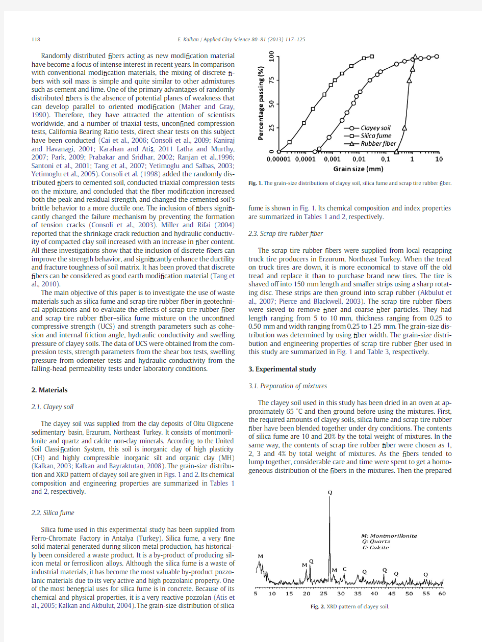
The clayey soil was supplied from the clay deposits of Oltu Oligocene sedimentary basin,Erzurum,Northeast Turkey.It consists of montmoril-lonite and quartz and calcite non-clay minerals.According to the United Soil Classi?cation System,this soil is inorganic clay of high plasticity (CH)and highly compressible inorganic silt and organic clay(MH) (Kalkan,2003;Kalkan and Bayraktutan,2008).The grain-size distribu-tion and XRD pattern of clayey soil are given in Figs.1and2.Its chemical composition and engineering properties are summarized in Tables1 and2,respectively.
2.2.Silica fume
Silica fume used in this experimental study has been supplied from Ferro-Chromate Factory in Antalya(Turkey).Silica fume,a very?ne solid material generated during silicon metal production,has historical-ly been considered a waste product.It is a by-product of producing sil-icon metal or ferrosilicon alloys.Although the silica fume is a waste of industrial materials,it has become the most valuable by-product pozzo-lanic materials due to its very active and high pozzolanic property.One of the most bene?cial uses for silica fume is in concrete.Because of its chemical and physical properties,it is a very reactive pozzolan(Atis et al.,2005;Kalkan and Akbulut,2004).The grain-size distribution of silica fume is shown in Fig.1.Its chemical composition and index properties are summarized in Tables1and2,respectively.
2.3.Scrap tire rubber?ber
The scrap tire rubber?bers were supplied from local recapping truck tire producers in Erzurum,Northeast Turkey.When the tread on truck tires are down,it is more economical to stave off the old tread and replace it than to purchase brand new tires.The tire is shaved off into150mm length and smaller strips using a sharp rotat-ing disc.These strips are then ground into scrap rubber(Akbulut et al.,2007;Pierce and Blackwell,2003).The scrap tire rubber?bers were sieved to remove?ner and coarse?ber particles.They had length ranging from5to10mm,thickness ranging from0.25to 0.50mm and width ranging from0.25to1.25mm.The grain-size dis-tribution was determined by using?ber width.The grain-size distri-bution and engineering properties of scrap tire rubber?ber used in this study are summarized in Fig.1and Table3,respectively.
3.Experimental study
3.1.Preparation of mixtures
The clayey soil used in this study has been dried in an oven at ap-proximately65°C and then ground before using the mixtures.First, the required amounts of clayey soils,silica fume and scrap tire rubber ?ber have been blended together under dry conditions.The contents of silica fume are10and20%by the total weight of mixtures.In the same way,the contents of scrap tire rubber?ber were chosen as1, 2,3and4%by total weight of mixtures.As the?bers tended to lump together,considerable care and time were spent to get a homo-geneous distribution of the?bers in the mixtures.Then the
prepared Fig.1.The grain-size distributions of clayey soil,silica fume and scrap tire rubber?
ber.
Fig.2.XRD pattern of clayey soil.
118 E.Kalkan/Applied Clay Science80–81(2013)117–125
mixtures have been mixed with the required amount of water ac-cording to the optimum moisture content.The weights of the mix-tures were determined according to the formulas below;
W CSF?W CtW SFe1TW CFB?W CtW RFe2TW CSFRF?W CtW SFtW RFe3Twhere W CSF,W CRF,and W CSFRF are the total dry weights of clayey soil–silica fume mixtures,clayey soil–scrap tire rubber?ber mixtures,and clayey soil–silica fume–scrap tire rubber?ber mixtures,respectively and W C,W SF,and W RF are the weights of clayey soil,silica fume and scrap tire rubber?ber,respectively.The component of the samples used in the experimental studies is summarized in Table4.
3.2.Preparation of samples
The mixtures of silica fume–clayey soil,scrap tire rubber?ber–clayey soil and silica fume–scrap tire rubber?ber–clayey soil mixtures were blended together in dry conditions.Then natural clayey soil and mix-tures were mixed with the required amount of water for optimum water content.All mixing was done manually and proper care was taken to prepare homogeneous mixtures at each stage of mixing.The uncon?ned compression and shear box tests were carried out on the cylindrical samples compacted at optimum water contents.The com-paction processes were performed by Standard Proctor test.After com-pactions of the clayey soil and the mixtures,cylindrical samplers were pressed into the compacted samples within the mold to obtain samples with appropriate length-to-diameter ratios for uncon?ned compressive and shear box tests.Then the cylindrical samples taken into the cylin-drical samplers were extruded using a hydraulic sample extractor.The samples of uncon?ned compression tests had35mm diameter by 70mm length.In the tests,at least three samples were tried for each combination of variables.After each sample was extracted from the cy-lindrical samplers,it was wrapped in plastic to prevent from water loss. The samples with60mm diameter and35mm length were used for the shear box tests.
3.3.Testing program
https://www.doczj.com/doc/2411766954.html,paction tests
To determine the optimum water contents of natural and modi?ed clayey soil samples and to prepare the samples for the uncon?ned com-pression and shear box tests,Standard Proctor tests were carried out by referring to the ASTM D698.During the compaction process,a soil at se-lected water content was placed in three layers into a mold of standard dimensions,with each layer compacted by25blows of rammer dropped from a distance of305mm,subjecting the soil to total compac-tion effort.This procedure was repeated for six numbers of water con-tents to establish a relationship between the dry unit weight and the water content for the clayey soil and the mixtures.The compaction curves were plotted from the data and the values of optimum water content and maximum dry unit weight were determined from the com-paction curves.The clayey soil and the mixtures were compacted at the optimum water content to prepare the samples for the uncon?ned
Table1
Chemical compositions of clayey soil and silica fume used in the study.
Property Clayey soil Silica fume
Compound
SiO2,%46.8385–95
Al2O3,%15.351–3
Fe2O3,% 6.810.5–1
CaO,%11.020.8–1.2 MgO,% 4.561–2
Na2O,%0.94–
K2O,% 1.23–
TiO2,%0.81–
Loss on ignition(LOI),%12.450.5–1
Table2
Engineering properties of clayey soil and silica fume used in this study.
Property Clayey soil Silica fume
Density
Density,(Mg/m3) 2.632–2.5 Grain size
Sand(2000–75μm),%2–
Silt(2–75μm),%6620
Clay(b2μm),%3280 Atterberg limits
Liquid limit,%72–
Plastic limit,%35–
Plasticity index,%37–
Speci?c surface area
Speci?c surface area,m2/g243.620.12
Soil classi?cation
Uni?ed Soil Classi?cation(USCS)CH–Mineralogy
Clay minerals
Montmorillonite x–
Non-clay minerals
Quartz x–
Calcite x–
Table3
Engineering properties of scrap tire rubber?ber used in this study.
Property Scrap tire rubber
Property
Fiber type Single?ber
Density,(Mg/m3) 1.153–1.198
Elastic modulus(MPa)1–97–22.96
Tensile strength(MPa)28.1
Extent at failure(%)44–55
Softening temperature(°C)175
Component
Styrene butadiene copolymer(%)62
Carbon block(%)31
Extender oil(%) 1.9
Zinc oxide(%) 1.9
Stearic acid(%) 1.2
Sulphur(%) 1.1
Accelerator0.7
Table4
Clayey soil,silica fume and scrap tire rubber?ber ratio of composite samples.
Materials(%)
Samples Clayey soil Silica fume Scrap tire rubber?ber Total
C100––100 CSF19010–100 CSF28020–100 CRF199–1100 CRF298–2100 CRF397–3100 CRF496–4100 CSFRF189101100 CSFRF288102100 CSFRF387103100 CSFRF486104100 CSFRF579201100 CSFRF678202100 CSFRF777203100 CSFRF876204100
C:clayey soil,CSF:clayey soil–silica fume mixture,CRF:clayey soil–?ber mixture, CSFRF:clayey soil–silica fume–?ber mixture.
119
E.Kalkan/Applied Clay Science80–81(2013)117–125
compression,shear box tests,odometer and the falling-head permeability tests.
3.3.2.Uncon?ned compression tests
The UCS values of clayey soil and modi?ed clayey soil samples were determined from the uncon?ned compressive tests in accordance with ASTM D2166.This test is widely used as a quick and economical meth-od of obtaining the approximate compressive strength of the cohesive soils.In this study,three cylindrical samples were prepared and tested for each combination of mixtures.The uncon?ned compressive tests were performed at a deformation rate of0.16mm/min.
3.3.3.Shear box tests
In order to determine the shear strength parameters of clayey soil and modi?ed clayey soil samples,a series of shear box tests was car-ried out in accordance with ASTM D3080.For these tests,samples were placed in the standard shear box apparatus with60mm in di-ameter and35mm in length.To obtain the shear strength parameters such as cohesion and internal friction angle,the values of shear stress versus the value of normal stress were plotted to construct a best?t straight line through the plotted points.The cohesion values were obtained from the intercept with the ordinate axis and the slops of the internal fraction angles from the slope.
3.3.
4.Odometer tests
Swelling pressure values of the natural and modi?ed clayey soil samples were obtained from odometer tests carried out according to ASTM D2435.The samples were all initially compacted at their op-timum moisture content in a Standard Proctor mold and extruded using a cutting ring before the one dimensional consolidation tests. The samples used in the tests were74mm in diameter and20mm high in standard Odometer apparatus(ASTM D2435).The swelling pressure of each sample was directly measured from the surcharge, which loads the sample.The sample was con?ned in the consolida-tion ring,and water was added to the sample,and it was allowed to swell.As the samples were swelling,the de?ection of the dial gage was set up to zero.As a result,the samples showed no further tenden-cy to swell and the maximum surcharge load,P ms,at that point was used for the calculation of the swelling pressure.The swelling pres-sure can be expressed as;
SP?P MS=Ae4Twhere swelling pressure(SP)is in kilopascals,P MS is the maximum surcharge load on the sample in kilonewtons,and A is the area of the sample,in square centimeters.
3.3.5.Falling-head permeability tests
The falling-head permeability tests were conducted in accordance with ASTM D5084.The samples were placed inside a cylindrical mold with a102mm in diameter and117mm in length and then allowed to?ow through the sample.The test apparatus consists of a mold with lids and a standpipe10mm in diameter and100mm in length. During the tests,prepared samples in molds were saturated under water pressure for two days,and then permeability values were calcu-lated for48h.The permeability values were calculated by the following equation:
k?aL=At ln h1=h2
eTe5T
where k is the permeability in centimeters per second,h1is the hydraulic head across sample at the beginning of the test(t=0)in centimeters,h2 is the hydraulic head across sample at the end of the test(t=t test)in cen-timeters,t is elapsed time in second,A is the across area of sample in square centimeters,a is the across area of standpipe in square centimeters and L is the length of sample in centimeters.3.3.6.Imaging tests
In order to evaluate the interaction between clayey soil and silica fume particles,clayey soil and modi?ed clayey soil samples were subjected to image analysis by using scanning electron microscope (SEM).Images of samples were magni?ed5000times by means of a SEM modeled Jeol6400SEM.After blending clayey soil and silica fume under dry conditions and mixing them with the required amount of water for optimum moisture content to obtain reaction between clayey soil and silica fume particles,all samples were allowed to air-dry to their initial water content at22°C up to water removing. After curing,all samples were subjected to imaging for microscopic analysis to determine the nature of the pores and the effect of varying the silica fume content on the pore structure.
4.Results and discussions
4.1.Effects of silica fume and tire rubber?ber on the compaction parameters
Standard proctor tests were carried out to determine the effect of sil-ica fume and tire rubber?ber on the compaction parameters such as maximum dry unit weight and optimum water content and results were summarized in Figs.3and4.It was observed that the maximum dry unit weight values decreased and the optimum water content values increased with the addition of silica fume.The decrease in the maximum dry unit weights was attributed to the addition of higher amounts of sil-ica fume,which?lled the voids of the silica fume-modi?ed clayey soil samples(Attom and Al-Sharif,1998;Kalkan and Akbulut,2002;Kalkan and Akbulut,2004).In the same way,the increase in the optimum water content was due to the change in the particle size distribution and surface area of the silica fume stabilized clayey soil samples(Pera et al.,1997;Kalkan,2006,2011).On the other hand,with the addition of tire rubber?ber both the maximum dry unit weight(Fig.3)and opti-mum moisture content(Fig.4)decreased.These decreases were attrib-uted to the low density and large speci?c surface area of tire rubber ?ber(Prabakar and Sridhar,2002;Akbulut et al.,2007;?enol,2012). 4.2.Effect of silica fume and scrap tire rubber?ber on the UCS
The effect of silica fume,scrap tire rubber?ber and silica fume–scrap tire rubber?ber mixtures on the UCS were illustrated in Figs.5and6.As can be seen in Fig.5,the silica fume increased the UCS value of clayey soil.As compared with clayey soil,the UCS value of silica fume-modi?ed clayey soil sample containing20%silica fume increased from92.8to 182kPa,which is0.97times more than that of unmodi?ed(Fig.6). The increase in the UCS is attributed to the internal friction of silica fume particles and chemical reaction between the silica fume
and Fig.3.Effect of the scrap tire rubber?ber on the maximum dry unit weight.
120 E.Kalkan/Applied Clay Science80–81(2013)117–125
clayey coil particles (Gillot,1968;Kalkan,2006,2009a,b;Kalkan and Akbulut,2004;Ola,1978).The clayey soil used in this study has signif-icant amounts of calcium containing compounds (Table 1)that can pro-duce Ca 2+and OH ?1ions.The active silica reacts with calcium and hydroxide forming calcium silicate hydrate gels.This chemical modi ?-cation likely causes stronger and more brittle forms of material compos-ing the clayey soil –silica fume mixture and decreases their volumetric shrinkage strain (Bell,1993;Kalkan,2011;Kalkan and Akbulut,2004;Sherwood,1993).
The effects of scrap tire rubber ?bers on UCS values of clayey soil and silica fume-modi ?ed clayey soil samples are given in Figs.5and 6.This ?gure indicates that the UCS values of ?ber-modi ?ed clayey soil and silica fume and ?ber-modi ?ed clayey soil have a tendency to increase ?rst,after a peak value,the UCS values decrease.It was found that the UCS values increased due to the rise of 2%?ber content from 92.8to 177.1kPa and from 182.7to 278.1kPa for the silica fume and silica fume-modi ?ed clayey soil samples,respectively.
To express the variation of the UCS,hydraulic conductivity and swelling pressure values as a percentage,these values were normalized equalizing these values of clayey soil samples to 100.These normalized values were depicted in Fig.6.It was observed that the percentage of in-crease in the UCS values was 96.88,90.78and 199.67%for the silica fume-modi ?ed clayey soils,rubber ?ber-modi ?ed clayey soil and silica fume and rubber ?ber-modi ?ed clayey soil,respectively (Fig.6).Ac-cording to the test results,the optimum tire rubber ?ber content is 2%.
Both the silica fume and rubber ?ber contents play an important role in the development of UCS.The results indicate that silica fume –rubber ?ber mixtures have more effect on the UCS than that of rubber ?ber.The increase in UCS is attributed to the internal
friction of silica fume particles and chemical reaction between silica fume and clay materials.
Interaction mechanism of ?ber/soil interface is complex.The previ-ous research results show that pullout response is in ?uenced by many factors,e.g.the con ?nement stress,soil dry density,displacement rate,embedded modi ?cation length,modi ?cation surface roughness,shape and so on (Bakeer et al.,1998;Beyerlein et al.,2001;Brandstetter et al.,2005;Khedkar and Mandal,2009;Li et al.,2005;Lopes and Ladeira,1996;Moraci and Recalcati,2006;Sieira et al.,2009).The main interac-tion mechanisms affecting the pullout resistance of extruded rubber ?ber particles are the skin friction,between soil and ?ber surface,and the bearing resistance that develops against the transversal element (Moraci and Gioffre,2006).The pullout response of rubber ?bers,also pointed out that the friction between soil and ?ber,the nature and the con ?nement of soil are the most important factors affecting pullout re-sponse of ?ber.After compaction,the ?ber is enwrapped by inter-locked or inter-bonded soil particles.After the ?ber is pulled out,some soil particles are attached on the ?ber surface.It indicates that the inter-facial soil structure is disturbed even broken during the shear process.Therefore,when shear occurs,the interfacial friction strongly depends on the resistance of soil particle rearrangement and rotation (Fig.7).The soil particle rotation occurs,when the resistance offered by mineral friction and mechanical interlock between adjacent soil particles is smaller than that between the particles and the manufactured material surface (Dove et al.,2006;Racana et al.,2003;Tang et al.,2010).
During compaction,some angular hard particles in soil may cause plastic deformation of ?ber body (Fig.8),especially at high compaction load.This phenomenon was con ?rmed by Tang et al.(2007),who inves-tigated the interface morphologies of ?ber-modi ?ed clayey
soil.
Fig.4.Effect of the scrap tire rubber ?ber on the optimum moisture
content.
Fig.5.Effect of the scrap tire rubber ?ber on the
UCS.
Fig.6.Variation of UCS,swelling pressure and hydraulic conductivity with the silica fume,?ber and silica fume –?ber
mixtures.
Fig.7.Sketch drawing of interfacial mechanical interactions between soil particles and ?ber (modi ?ed from Tang et al.,2010).
121
E.Kalkan /Applied Clay Science 80–81(2013)117–125
4.3.Effect of silica fume and scrap tire rubber ?ber on the strength parameters
The shear box test results showed that the cohesion and internal friction angle values increased by the addition of silica fume (Figs.9and 10).This indicates the addition of silica fume increases shear strength parameters for the same conditions.The maximum cohesion value of silica fume-modi ?ed clayey soil samples was observed for 20%silica fume as 192.7kPa,which is 1.1times more than that of the unmodi ?ed clayey soil samples.Meanwhile,the maximum inter-nal friction angle value observed from modi ?ed clayey soil containing 20%silica fume was 28,which is 1.7times more than that of the unmodi ?ed clayey soil samples.In literature,Ola (1978)and Gillot (1968)have reported that soil type,its composition,mineralogy,par-ticle shape,and particle size distribution in ?uence the results of soil modi ?cation.The increase in the cohesion and internal friction angle was attributed to the very ?ne particle size and internal friction of silica fume particles and chemical reaction between silica fume and clayey soil particles (Kalkan,2009a;Kalkan and Akbulut,2004).
The relationship between shear strength parameters and scrap tire rubbe ?ber was illustrated in Figs.9and 10.It is indicated that the per-centage rubber ?ber and silica fume –?ber mixture content plays an im-portant role in the development of the shear strength parameters cohesion and internal friction angle.The cohesion and internal friction angle of the samples increase with the increasing ?ber content up to 2%.It was found that the cohesion values increased due to the rise of 2%?ber content from 176to 214kPa and from 176to 268kPa for
clayey soil and modi ?ed clayey soil containing 20%silica fume,respec-tively.The increase in the cohesion of ?ber-modi ?ed clayey soil samples might be due to the increase in the con ?ning pressure due to the devel-opment of tension in the ?ber,and the moisture content in the ?ber fa-vors the formation of absorbed water layer on the clay particles,which enables the modi ?ed soil to act as a single coherent matrix of soil –?ber mass (Prabakar and Sridhar,2002).In general,the internal friction angle value of each modi ?ed sample increased,and these values ranged from 16to 32°and from 16to 48°for clayey soil and modi ?ed clayey soil containing 20%silica fume,respectively.
In the literature it is noted by Tang et al.(2010)that after compac-tion,the ?ber is enwrapped by inter-locked or inter-bonded soil parti-cles.After the ?ber is pulled out,some soil particles are attached on the ?ber surface.It indicates that the interfacial soil structure is dis-turbed even broken during the shear process.Therefore,when shear occurs,the interfacial friction strongly depends on the resistance of soil particle rearrangement and rotation.Normally,the less likely the soil particles rearrange during shearing or the more inter-locked the soil particles,the higher is the interfacial resistance to shear.The soil particle rotation would occur,when the resistance offered by mineral friction and mechanical interlock between adjacent soil particles is smaller than that between the particles and manufactured material surface (Dove et al.,2006;Frost and Han,1999;Tang et al.,2010).
4.4.Effect of scrap tire rubber ?ber on the failure characteristics The failure characteristics of clayey soil and modi ?ed clayey soil samples with silica fume,?ber and silica fume –?ber mixture are illus-trated in Fig.11.It is observed that the addition of silica fume and ?ber has a signi ?cant in ?uence on the failure characteristics of mod-i ?ed samples.The high degree of stiffness of the attached hydration crystals also toughened the distributed ?bers,which act similarly to plant roots in distributing the stresses in a broader area and inhibiting ?ssure propagation.Therefore,the combined silica fume and ?ber in-clusions increase the ef ?ciency of transfer of the load from matrix to ?bers.Furthermore,the hydration of the silica fume binds the soil particles together and makes the matrix compact,and causing an in-crease in normal stress around the ?ber body and the effective con-tact area.As a result,the static friction coef ?cient between ?ber and composite matrix is increased (Tang et al.,2007).It is shown from Fig.11that there is a difference in the size of the cracks in the surface of these four samples after compression failure.It is clearly shown that big cracks gradually vanish and small ones appear instead of them while the addition of 2%?ber content.Similar trends have been obtained from some experimental works by adding lime –?ber (Cai et al.,2006),cement –?ber (Tang et al.,2007,2010
).
Fig.8.Sketch drawing of contact condition between hard soil particles and ?ber surface under press (modi ?ed from Tang et al.,2010
).
Fig.9.Effect of the scrap tire rubber ?ber on the
cohesion.
Fig.10.Effect of the scrap tire rubber ?ber on the internal friction angle.
122 E.Kalkan /Applied Clay Science 80–81(2013)117–125
4.5.Effect of silica fume and scrap tire rubber ?ber on the hydraulic conductivity
Fig.12presents the effect of silica fume,?ber and silica fume –?ber mixtures on the hydraulic conductivity of clayey soil.The hydraulic con-ductivity values steadily decreased with increasing silica fume content and the low values were ?nally reached in the 20%silica fume-modi ?ed clayey soil.The hydraulic conductivity values of silica fume-modi ?ed clayey soil samples decreased from 1.86×10?7to 5.53×10?8cm/s.The decrease in the hydraulic conductivity values is due to the decreas-ing void ratio of the silica fume-modi ?ed samples.
As can be seen in Fig.12,scrap tire rubber ?ber increased the hy-draulic conductivity of ?ber-modi ?ed clayey soil samples,but silica fume –?ber mixtures decreased the hydraulic conductivity.As com-pared with natural clayey soil samples,it was found that the hydrau-lic conductivity of 2%?ber-modi ?ed clayey soil samples increased from 1.86to 2.86×10?7cm/s.On the contrary,the hydraulic con-ductivity of 20%silica fume and 2%?ber-modi ?ed clayey soil samples decreased from 1.86×10?7to 6.45×10?8cm/s.The increase in hy-draulic conductivity was attributed to the rubber ?ber particles in the modi ?ed samples.The ?ber surface caused the water to move easily in the ?ber-modi ?ed clayey soil samples.The decrease in the hydrau-lic conductivity values was due to the decreasing void ratio of the modi ?ed clayey soil samples containing silica fume (Kalkan,2009a;Kalkan and Akbulut,2004).
4.6.Effect of silica fume and scrap tire rubber ?ber on the swelling pressure
The effect of silica fume and scrap tire rubber ?ber on the swelling pressure was investigated and the results were illustrated in Fig.13.The swelling pressure steadily decreased with increasing silica fume content.With the addition of 20%silica fume,the swelling pressure
decreased from 230to 17kPa.The decrease in the swelling pressure is due to the addition of low-plastic materials and the interaction be-tween clay and silica fume particles (Kalkan,2006).The addition of sil-ica fume increased the pH values.The increase in pH values decreased the relative clay mineral contents (Eades,1962;Kalkan,2009b ).The modi ?ed clayey soil samples with low relative clay mineral contents and low liquid limit displayed low swelling pressure behavior.
The variations of swelling pressure with scrap tire rubber ?ber are plotted in Fig.13.It is observed that silica fume and rubber ?ber contents caused the decrease in swelling pressure.The swelling pressure values decreased from 230to 204kPa,from 230to 30kPa and from 230to 17kPa for the 2%?ber-modi ?ed clayey soil,10%silica fume and 2%?ber-modi ?ed clayey soil and 20%silica fume and 2%?ber-modi ?ed clayey soil samples,respectively.The minimum swelling pressure is recorded as 17kPa from 20%silica fume and 2%?ber-modi ?ed clayey soil sample (Fig.13).The decrease in swelling pressure could also be at-tributed to the presence of ?bers,which create drainage paths for the dis-sipation of pore pressures of a loaded soil sample.Another reason could be that the ?bers,being tensile elements,restrain the swelling pressures generated during loading by enhancing soil shear strength (Cai et al.,2006;Puppala and Musenda,1998).4.7.Image analysis
Fig.14shows SEM micrographs of the silica fume-modi ?ed clayey soil samples.It is shown from Fig.14A that large continuous pores among the clayey soil particles provide a large portion of the total void ratio while small connected pores exist among the micro-?ne sil-ica fume particles.It is seen from the images that silica fume particles cover the surrounding clayey soil particles and ?ll the voids of the modi ?ed clayey soil samples.In the samples with 10%silica fume con-tent,grain surfaces are partly covered by silica fume particles
and
Fig.11.Effects of silica fume,?ber and silica fume –?ber mixtures on the failure characteristics;(A)natural clayey soil,(B)20%silica fume –modi ?ed clayey soil,(C)2%?ber-modi ?ed clayey soil and (D)20%silica fume and 2%?ber-modi ?ed clayey
soil.
Fig.12.Effect of the silica fume and ?ber on the hydraulic
conductivity.Fig.13.Effect of the silica fume and scrap tire rubber ?ber on the swelling pressure.
123
E.Kalkan /Applied Clay Science 80–81(2013)117–125
most of the pore spaces still contain air (Fig.14B).In the samples with 20%silica fume content,grain surfaces are covered by silica fume par-ticles in signi ?cant ratios.The silica fume particles settle in the pore spaces among the clayey soil particles,and then the settled silica fume particles react to form hydration products in the surrounding ?ne-grained soil particles (Fig.14C).This textural event causes a sig-ni ?cant decrease in swelling pressure and swelling potential.A de-tailed examination of each micrograph reveals that most of the ?occulation products are deposited on the surfaces of the soil grains or at the contact points.These micrographs and the experimental re-sults above have also revealed the possibility that a chemical reaction
with silica fume and clay particles may occur (Kalkan,2011;Kalkan and Akbulut,2004).5.Conclusion
The following conclusions are derived from this investigation:?The silica fume,scrap tire rubber ?ber and silica fume –scrap tire rub-ber ?ber mixtures increased the UCS.Although the UCS values of all modi ?ed clayey soil samples increased with increasing silica fume and ?ber content,it was observed that the maximum UCS value was obtained by addition of 20%silica fume –2%?ber mixture.
?The shear box test results indicate the addition of silica fume in-creases shear strength parameters.The maximum cohesion and in-ternal friction angle values were obtained by addition of 20%silica fume –2%?ber mixture.
?The hydraulic conductivity and swelling pressure decreased with the addition of silica fume –?ber mixture.The maximum improve-ment for the hydraulic conductivity and swelling pressure has been observed by using 20%silica fume –2%?ber mixture content.?Observations of SEM showed that the structure of raw clay samples could be changed through silica fume contents in the sample.The structure of a material had a signi ?cant in ?uence on its engineering properties such as permeability,strength and stiffness.
?The investigation showed that the silica fume –?ber mixture is a valuable material to modify the properties of clayey soils.In the geotechnical applications,the silica fume –?ber mixture in the ap-plications should be taken into account due to its positive effects on the uncon ?ned compressive strength,hydraulic conductivity and swelling pressure.
?It is conclude that the silica fume –?ber mixture can be used for mod-i ?cation of clayey soils.In addition,this mixture can potentially re-duce stabilization costs by utilizing wastes in a cost-effective manner.References
Abuel-Naga,H.M.,Bergado,D.T.,Chaiprakaikeow,S.,2006.Innovative thermal tech-nique for enhancing the performance of prefabricated vertical drain during the preloading process.Geotextiles and Geomembranes 24(6),359–370.
Aitcin,P.C.,Ballivy,G.,Parizeau,R.,1984.The use of condensed silica fume in grouting.
Innovative Cement Grouting.Publication SP-83,ACI,Detroit MI,USA 1–18.
Akbulut,S.,Hasiloglu,A.S.,Pamukcu,S.,2004.Data generation for shear modulus and
damping ratio in reinforced sands using adaptive nouro-fuzzy inference system.Soil Dynamics and Earthquake Engineering 24,805–814.
Akbulut,S.,Arasan,S.,Kalkan,E.,2007.Modi ?cation of clayey soils using scrap tire rub-ber and synthetic ?bers.Applied Clay Science 38,23–32.
Asavasipit,S.,Nanthamontry,W.,Polprasert,C.,2001.In ?uence of condensed silica
fume on the properties of cement based solidi ?ed wastes.Cement and Concrete Research 31,1147–1152.
Atis,C.D.,Ozcan,F.,K ?l ?c,A.,Karahan,O.,Bilim,C.,Severcan,M.H.,2005.In ?uence of dry
and wet curing conditions on compressive strength of silica fume concrete.Build-ing and Environment 40,1678–1683.
Attom,M.F.,Al-Sharif,M.M.,1998.Soil stabilization with burned olive waste.Applied
Clay Science 13,219–230.
Bakeer,R.M.,Abdel-Rahman,A.H.,Napolitano,P.J.,1998.Geotextile friction mobiliza-tion during ?eld pull out test.Geotextiles and Geomembranes 16,73–85.
Bell,F.G.,1993.Engineering Treatment of Soils.E and FN Spon,an imprint of Chapmen
and Hall,Boundary Row,London.
Beyerlein,J.I.,Zhu,Y.T.,Mahesh,S.,2001.On the in ?uence of ?ber shape in bone-shaped
short-?ber https://www.doczj.com/doc/2411766954.html,posites Science and Technology 61,1341–1357.
Brandstetter,J.,Kromp,K.,Peterlik,H.,Weiss,R.,2005.Effect of surface roughness on
fraction in ?ber-bundle pull-out https://www.doczj.com/doc/2411766954.html,posites Science and Technology 65,981–988.
Cai,Y.,Shi,B.,Ng,C.W.W.,Tang,C.,2006.Effect of polypropylene ?ber and lime admix-ture on engineering properties of clayey soil.Engineering Geology 87,230–240.Cetin,H.,Fener,M.,Gunaydin,O.,2006.Geotechnical properties of tire-cohesive clayey
soil mixtures as a ?ll material.Engineering Geology 88(1–2),110–120.
Charan,H.D.,1995.Probabilistic analysis of randomly distributed ?ber reinforced soil.
(Ph.D.Thesis)Department of Civil Engineering,University of Roorkee,Roorkee,India.Chen,F.H.,1988.Foundations on Expansive Soils.Elsevier.
Chu,J.,Bo,M.W.,Choa,V.,2006.Improvement of ultra-soft soil using prefabricated ver-tical drains.Geotextiles and Geomembranes 24(6),339–348.
Consoli,C.N.,Prietto,D.M.,Ulbrich,L.A.,1998.In ?uence of ?ber and cement addition on
behavior of sandy soil.Journal of Geotechnical and Geoenvironmental Engineering 124(12),1211–
1214.
Fig.14.Images of silica fume-modi ?ed clayey soil with (A)0%silica fume,(B)10%silica fume and (C)20%silica fume.
124 E.Kalkan /Applied Clay Science 80–81(2013)117–125
Consoli,C.N.,Vendruscolo,M.A.,Prietto,P.D.M.,2003.Behavior of plate load tests on soil layers improved with cement and?ber.Journal of Geotechnical and Geoenvironmental Engineering129(1),96–101.
Consoli,N.C.,Vendruscolo,M.A.,Fonini,A.,Dalla Rosa,F.,2009.Fiber reinforcement effects on sand considering a wide cementation range.Geotextiles and Geomembranes27
(3),196–203.
Dove,J.E.,Bents,D.D.,Wang,J.,Gao,B.,2006.Particle–scale surface interactions of non-dilative interface systems.Geotextiles and Geomembranes24,156–168. Eades,J.,1962.Reactions of Ca(\OH)with clay minerals in soil stabilization.(PhD Thesis)Geology Department,University of Illinois,Urbana.
Frost,D.J.,Han,J.,1999.Behavior of interfaces between?ber-reinforced polymers and sands.Journal of Geotechnical and Geoenvironmental Engineering125(8),633–640. Gillot,J.E.,1968.Clay in Engineering Geology.Elsevier,New York.
Gray,D.H.,Ohashi,H.,1983.Mechanics of?ber reinforcing in sand.Journal of Geotech-nical Engineering Division,ASCE109(3),335–353.
Gregory,G.H.,Chill,D.S.,1998.Stabilization of earth slope with?ber reinforcement.
Proceedings6th International Conference on Geosynthetics,Atlanta. Hausmann,M.R.,1990.Engineering Principles of Ground Modi?cation.McGraw-Hill, New York.
Jones,C.J.F.P.,1985.Earth Reinforcement and Soil Structure.Butterworth's Advanced Series in Geotechnical Engineering.
Kalkan,E.,2003.The improvement of geotechnical properties of Oltu(Erzurum)clayey deposits for using them as barriers.(PhD Thesis(in Turkish))Ataturk University, Graduate School of Natural and Applied Science,Erzurum,Turkey.
Kalkan,E.,2006.Utilization of red mud as a stabilization material for preparation of clay liners.Engineering Geology87(3–4),220–229.
Kalkan,E.,2009a.In?uence of silica fume on the desiccation cracks of compacted clayey soils.Applied Clay Science43,296–302.
Kalkan,E.,2009b.Effects of silica fume on the geotechnical properties of?ne-grained soils exposed to freeze and thaw.Cold Regions Science&Technology58,130–135. Kalkan,E.,2011.Impact of wetting–drying cycles on swelling behavior of clayey soils modi?ed by silica fume.Applied Clay Science52(4),345–352.
Kalkan,E.,2012.Effects of waste material–lime additive mixtures on mechanical prop-erties of granular soils.Bulletin of Engineering Geology and the Environment71
(1),99–103.
Kalkan,E.,Akbulut,S.,2002.Improving of shear strength of natural clay liners from clay deposits NE Turkey.3rd International Conference on Landslides,Slope Stability and the Safety of Infrastructures.Cl-Premier Ltd,Singapore,pp.295–300.
Kalkan,E.,Akbulut,S.,2004.The positive effects of silica fume on the permeability, swelling pressure and compressive strength of natural clay liners.Engineering Ge-ology73,145–156.
Kalkan,E.,Bayraktutan,M.S.,2008.Geotechnical evaluation of Turkish clay deposits:
a case study in Northern Turkey.Environmental Geology55,937–950.
Kaniraj,S.R.,Havanagi,V.G.,2001.Behavior of cement-stabilized?ber-reinforced?y ash–soil mixtures.Journal of Geotechnical and Geoenvironmental Engineering127(7),574–584. Karahan,O.,Ati?,C.D.,2011.The durability properties of polypropylene?ber reinforced ?y ash concrete.Materials and Design32,1044–1049.
Kayabali,K.,1997.Engineering aspects of a novel land?ll liner material:bentonite amended natural zeolite.Engineering Geology46,105–114.
Khedkar,M.S.,Mandal,J.N.,2009.Pullout behavior of cellular reinforcements.Geotextiles and Geomembranes27(4),262–271.
Latha,G.M.,Murthy,V.S.,2007.Effect of reinforcement form on the behavior of geosynthetic reinforced sand.Geotextiles and Geomembranes25(1),23–32.
Li,Y.,Mai,Y.W.,Ye,L.,2005.Effects of?ber surface treatment on fracture-mechanical properties of sisal–?ber https://www.doczj.com/doc/2411766954.html,posite Interfaces12(1–2),141–163. Lopes,M.L.,Ladeira,M.,1996.In?uence of the con?nement,soil density and displacement rate on soil–geogrid interaction.Geotextiles and Geomembranes14,543–554. Maher,M.H.,Gray,D.H.,1990.Static response of sand reinforced with randomly dis-tributed?bers.Journal of Geotechnical Engineering116,1661–1677.
Miller,C.J.,Rifai,S.,2004.Fiber reinforcement for waste containment soil liners.Journal of Environmental Engineering130(8),981–985.
Moraci,N.,Gioffre,D.,2006.A simple method to evaluate the pullout resistance of extrud-ed geogrids embedded in a compacted granular soil.Geotextiles and Geomembranes 24,116–128.Moraci,N.,Recalcati,P.,2006.Factors affecting the pullout behaviour of extruded geogrids embedded in a compacted granular soil.Geotextiles and Geomembranes24,220–242. Musenda,C.,1999.Investigation of the effects of using discrete randomly distributed ?ber reinforcement in expansive foundation soils.(Master's Thesis)University of Texas at Arlington.
Nataraj,M.S.,McManis,K.L.,1997.Strength and deformation properties of soils reinforced with?brillated?bers.Geosynthetics International4(1),65–79. Nelson,J.D.,Miller,D.J.,1992.Expansive Soils:Problems and Practice in Foundation and Pavement Engineering.John Wiley and Sons,Inc.,New York.
Ola,S.A.,1978.Geotechnical properties and behavior of some stabilized Nigerian later-itic soils.The Quarterly Journal of Engineering Geology11,145–160.
Park,S.S.,2009.Effect of?ber reinforcement and distribution on uncon?ned compres-sive strength of?ber-reinforced cemented sand.Geotextiles and Geomembranes 27(2),162–166.
Park,T.,Tan,S.A.,2005.Enhanced performance of reinforced soil walls by the inclusion of short?ber.Geotextiles and Geomembranes23(4),348–361.
Pera,J.,Boumaza,R.,Ambroise,J.,1997.Development of pozzolanic pigment from red mud.Cement and Concrete Research27,1513–1522.
Pierce,C.,Blackwell,M.,2003.Potential of scrap tire rubber as lightweight aggregate in ?owable?ll.Waste Management23,197–208.
Prabakar,J.,Sridhar,R.S.,2002.Effect of random inclusion of sisal?bre on strength be-havior of soil.Construction and Building Materials16,123–131.
Prabakar,J.,Dendorkar,N.,Morchhale,R.K.,2004.In?uence of?y ash on strength be-havior of typical soils.Construction and Building Materials18,263–267. Puppala,A.J.,Musenda,C.,1998.Investigation of geo?ber reinforcement method on strength,swell,and shrinkage characteristic of soils.Presented at Fifth International Conference on Composites Engineering,Las Vegas.
Puppala, A.J.,Musenda,C.,2002.Effects of?ber reinforcement on strength and volume change in expansive soils.Transportation Research Record134–140 (Paper No:00-0716).
Racana,N.,Grediac,M.,Gourves,R.,2003.Pull-out response of corrugated geotextile strips.Geotextiles and Geomembranes21,265–288.
Ranjan,G.,Vasan,R.M.,Charan,H.D.,1996.Probabilistic analysis of randomly distribut-ed?ber-reinforced soil.Journal of Geotechnical Engineering Division,ASCE122
(6),419–426.
Sandra,T.,Jeffrey,C.E.,1992.The effects of?ller and admixtures on grout performance.
Grouting,soil improvement,and geosynthetics.Geotechnical Engineering Division of ASCE,USA1,337–349.
Santoni,R.L.,Tingle,J.S.,Webster,S.L.,2001.Engineering properties of sand–?ber mixtures for road construction.Journal of Geotechnical and Geoenvironmental Engineering127(3),258–268.
Senol,A.,2012.Effect of?y ash and polypropylene?bres content on the soft soils.
Bulletin of Engineering Geology and the Environment71(2),379–387. Sherwood,P.T.,1993.Soil Stabilization with Cement and Lime.State-of-the-Art Review, Transportation Research Laboratory,HMSO,London.
Sieira,A.C.C.F.,Gerscovich,D.M.S.,Sayao,A.S.F.J.,2009.Displacement and load transfer mechanisms of geogrids under pullout condition.Geotextiles and Geomembranes 27(4),241–253.
Steinberg,M.,1998.Geomembranes and the Control of Expansive Soils in Construction.
McGray-Hill,New York.
Tang,C.S.,Shi,B.,Gao,W.,Chen,F.,Cai,Y.,2007.Strength and mechanical behavior of short polypropylene?ber reinforced and cement stabilized clayey soil.Geotextiles and Geomembranes25,194–202.
Tang,C.S.,Shi,B.,Zhao,L.Z.,2010.Interfacial shear strength of?ber reinforced soil.
Geotextiles and Geomembranes28,54–62.
Vidal,H.,1969.The principle of reinforced earth.Highway Research Record No:282, 1–16.
Yarba??,N.,Kalkan,E.,Akbulut,S.,2007.Modi?cation of freezing–thawing properties of granular soils with waste additives.Cold Regions Science and Technology48,44–54. Yetimoglu,T.,Salbas,O.,2003.A study on shear strength of sands reinforced with randomly distributed discrete?bers.Geotextiles and Geomembranes21,103–110. Yetimoglu,T.,Inanir,M.,Inanir,O.E.,2005.A study on bearing capacity of randomly distributed?ber-reinforced sand?lls overlying soft clay.Geotextiles and Geomembranes 23(2),174–183.
125
E.Kalkan/Applied Clay Science80–81(2013)117–125
汽车轮胎常见的故障有哪些 花纹 一般来说,正常使用的家用轿车可以每6万公里或两年更换一次轮胎,但对于花纹磨损严重的轮胎则应提早更换。现在的快修店都 有花纹磨损标尺,车主可以买一把,随时检测自己轮胎的花纹磨损 状况。此外,胎面裂纹增多也是老化严重的象征,平时可以适当喷 一些轮胎保护蜡,还有就是开车时尽量不要压到腐蚀性的液体。 扎洞 您的爱车被扎过轮胎吗?如果有那么是多长时间前的事了呢?其实对于已经补了很长时间的轮胎来说,即使暂时用起来没问题,但在 极限负载下的承受力也会大不如从前;另外,同一条轮胎上如果已经 扎了3个以上的洞,我们还是建议您尽快把它换掉。 石子 有些车主经常会听见自己的爱车在行驶时会发出“啪啪”的声音,但车用起来却也没有故障,这时您就要检查一下是不是有小石子卡 在轮胎花纹里了。其实只要平时抽空用钥匙将胎面纹路里的这些小 石粒挖出来,不仅会使轮胎的制动抓地更稳定,而且还避免了胎噪。 鼓包 汽车如果以高速驶过凹坑、障碍物及马路牙子时,轮胎局部在巨大的撞击力下将发生严重变形,从而内部压力瞬间增大,这样的直 接后果就是造成胎侧帘子线断裂而引起鼓包。另外在相同冲击力度下,低扁平比的轮胎比高扁平比轮胎更容易造成胎侧鼓包。已经发 生了鼓包的轮胎必须立即更换,否则就有爆胎的隐患。 气压
现在的大多数家用轿车都使用了无内胎的子午线轮胎,对于前驱车来说由于发动机、变速箱等重要驱动部件都压在前部,所以前轮 有时看起来会有点瘪,但目测是不准确的,一定要用专用的胎压表 测量。一般来说前轮的气压在2.0帕—2.2帕之间,(由于每辆车的 用途和设计各有不同,所以最好参考使用说明书上标定的厂方数值),夏天可以适当低一些。 备胎 要想备胎起到真正应急的作用,平时就要重视对其的保养。首先,要经常检查备胎气压;其次,备胎要注意防油蚀,备胎是橡胶制品, 最怕各种油品的侵蚀。轮胎沾油后,很快就会发生胀蚀,这会大大 降低备胎的使用寿命。最后,备胎的寿命在4年左右,很多车主错 误地认为备胎不用就一直是新的,其实过了4年即使备胎一次也没 有使用过也要更换,否则备胎就成了废胎。 一边磨损量过大 主要原因是前轮定位失准。当前轮的外倾角过大时,轮胎的外边形成早期磨损,外倾角过小或没有时,轮胎的内边形成早期磨损。 中央部分早期磨损 主要原因是充气量过大。适当提高轮胎的充气量,可以减少轮胎的滚动阻力,节约燃油。但充气量过大时,不但影响轮胎的减振性能,还会使轮胎变形量过大,与地面的接触面积减小,正常磨损只 能由胎面中央部分承担,形成早期磨损。如果在窄轮辋上选用宽轮胎,也会造成中央部分早期磨损。 个别轮胎磨损量大 个别车轮的悬挂系统失常、支承件弯曲或个别车轮不平衡都会造成个别轮胎早期磨损。出现这种情况后,应检查磨损严惩车轮的定 位情况、独立悬挂弹簧和减振器的工作情况,同时应缩短车轮换位 周期。 两边磨损过大
关于汽车轮胎理赔的规定 一、适用范围:本规定适用于所有车型。 二、是否理赔的判定基准: 1、 以下情况给予理赔: 钢丝带束层脱层(胎面与带束层、带束层与带束层、带束层与胎体之间分离)原因为:粘接力不良、硫化不良、橡胶间有异物,无外伤痕迹的理赔。 2、 以下情况不予理赔: 2.1修补过的轮胎,翻新轮胎不予理赔,。 2.2因使用不当导致的早期损坏的轮胎不予理赔。 2.3橡胶表面发生龟裂的不予理赔。 2.4其它经鉴定不属于轮胎品质问题的不予理赔。 2.5伪造质量缺陷、标识、生产编号、层级的轮胎不理赔。 2.6低气压、超负荷、高速行驶时使用不当引起的热脱层,撞击破裂或起鼓,外伤处水分、灰尘等异物进入引起的脱层等不理赔。 3、 不予理赔的故障模式: 胎面划伤 原因:气压过高,或臭氧引起的橡胶龟裂,行驶中被尖锐物冲击、划伤产生。
● 带束层折断 原因:因路面(未铺装路面)或其他障碍物冲击等原因导致带素层 钢丝局部折断 ● 钉子或尖锐物刺穿 钉子或尖锐物刺穿 ● 胎面啃坏或掉块 原因:刹车频繁、使用用途不适合的产品、气压过高/速度过快 ● 冠爆 原因:在铺装路面与未铺装路面连接处或障碍物,因速度过快等引起 的过渡冲击,导致带束层钢丝完全折断。
冠爆 胎面碎片状磨损 ● 胎面碎片状磨损 原因:在非铺装路面或其他恶劣路面使用 ● 胎面异常磨损 原因:四轮定位(前束)不当,车轴负荷过大,未定期进行轮胎换位(偏磨);气压过高(轮胎中部磨损过重),气压过低(轮胎两侧磨损过重) ● 胎侧外伤 原因:道路损伤、边石切割、尖锐物冲击
● 胎侧鼓包 原因:有擦伤痕迹,轮辋相应凸缘处有橡胶积压的黑色痕迹(胎里有明显“一”裂痕或褶皱),属车辆行驶中遇路面凹陷或障碍物后,未予减速或避让不及时,产生瞬间极强冲击力,使胎体极度变形,被轮辋凸缘切伤断纱,充气后表现为鼓包。 ● 修补 修补 胎缘线折断 ● 胎缘线折断 原因:轮胎气压超过危险气压,错误使用拆装胎机,轮辋使用不当或轮辋变形、损伤产生
从颜色到结构:全面解析轮胎的秘密 ▊生产二科:陈庆 轮胎大家绝不陌生,幼儿园的孩子闭着眼都能画出一个轮子,但很多开了一辈子汽车的司机也不明白轮胎这玩意儿里到底有什么玄机。您一定好奇轮胎有什么秘密,不就是圆形、充气的吗?要知道,轮胎作为车辆与路面接触的唯一媒介,对于车辆的性能有着直接影响。瞧,这么重要的东西怎么能没有秘密?让我们来探究一下。 ●轮胎历史 就像评书中的开始一样,想知道轮胎有什么秘密咱们得先 了解它的身世,由于篇幅限制咱们只看看乘用车轮胎,商用车轮胎 且听下回分解。好了,言归正传,第一个空心轮胎是1845年英国人 罗伯特?汤姆逊发明的。他提出用压缩空气充入弹性囊,以缓和运动 时的冲击,尽管当时的轮胎是用皮革和涂胶帆布制成,然而这种轮胎已经显示出滚动阻力小的优点,罗伯特?汤姆逊并以《马车和其他车辆的车轮改良》为题,获得了英国政府的专利。同年12月10日第一条充气轮胎诞生,第一个购买充气轮胎的人是个名叫罗列的贵族,四个轮胎的价钱合计为四十四磅二先令,要知道当时一英镑可以兑换白银三两,而当年英国国民生产总值才1000多万英镑。
1868年,美国人查尔斯?古德伊尔(Charles Goodyear)发明硫化 橡胶的方法,使橡胶能运用在轮胎上,古德伊尔先生虽取得专利但并未因此 致富(1898年美国一家新成立的轮胎公司为了纪念他的贡献,把公司命名为固特异轮胎公司)。 1887年12月,英国兽医约翰?邓禄普看到他的儿子在 布满石头的庭院里骑着三轮 车,思索如何使车轮更软以吸 收震荡,于是发明用充气的橡胶管套在木制轮辐上,现代轮胎的原型诞 生了。1903年,J?F?帕玛先生发明了斜纹纺织品,这种斜纹纺织品的发 明促成了斜交轮胎的发展,1930年米其林公司申请了带内胎轮胎(无内胎轮胎前身);1946年获得举世闻名的子午线轮胎专利。看看,很多轮胎大厂都到齐了。 ●轮胎为什么是黑色 大家都知道轮胎主要由橡胶组成,橡胶大家没见过但也大概知道颜色,但您想过为什么以橡胶为原料的轮胎是黑色的吗?其实这主要是由轮胎生产时的添加剂决定的,早在十九世纪,橡胶轮胎由于添加剂的不同,其颜色并不固定。到1915年,由于在轮胎制造时加入了碳黑也称碳烟(carbon black),橡胶呈现墨水般的纯黑色,而且耐磨性达到前所未有的水准。此后,橡胶轮胎进入黑色一统天下的漫长时期。 到了二十世纪五十年代,国外许多拥有轿车的人为了显示自己的财富与社会地位,纷纷把轮胎的外侧壁刷上白色油漆,以区别他人,体现个性。但是这种轮胎美容法最大的缺点就是轮胎使用一段时间后,
造成轿车子午胎鼓包的原因分析 随着我国汽车工业的蓬勃发展及道路状况的不断改善,各汽车厂家对原配胎的质量提出了更高的要求。现在针对引起轿车子午胎鼓包的原因进行分析,现汇总如下: 1、帘线稀线 有帘线稀线问题的轮胎,一般在轮胎充气后即可发现,或在使用不长的时间内就暴露出来。由帘线造成鼓包的位置主要在胎侧部位,有时两边对称。因帘线稀线造成的鼓包的轮胎所占的比例是比较大的,约占鼓包轮胎总数的三分之二。 在不充气的状态下,帘线稀线从轮胎表面是很难看出来的。用手触摸,特别是从内侧触摸,可敏感地感觉到起包处的厚度比其它部位厚度稍薄,有个凹坑状,解剖后,内侧凹坑处呈现一个弧形,狐的中部最薄,其厚度一般约为正常部位厚度的1/2。 从断面看,此处的帘线密度明显较小。在正常密度下,帘线是一根挨着一根的。可是鼓包处的帘线密度就不一样了,两根帘线之间有1或2mm,甚至更大的间隙。另外,断面帘线的排列呈外弧形,弧中部胶面最薄,有的甚至看到露线现象。 造成帘线稀线的原因是多方面的。但是,在设计合理的情况下,若半成品部件的尺寸能够达到标准,只要精心操作、仔细检查,帘线稀线是可以避免的。 2、帘布接头开 从表面看或用手触摸,由帘布接头开造成鼓包的特征与帘线稀线造成的鼓包差不多。若不解剖检查,鼓包会被误认为由帘线稀线所造成的。 在轮胎出厂前,帘布接头开用肉眼是难以发现的,因为帘布上有一定厚度的橡胶覆盖着。剖开鼓包处视其表面,可以看到帘线的密度是正常的,只是在长度内无帘线,或少一层帘布。这样,此处胎侧的总厚度较其它正常厚度稍薄,强度也相应减少。因而在轮胎充气时,此处是最薄弱的地方,容易造成鼓包。造成帘布接头开的主要是帘布裁断工序和成型工序。 3、胎侧胶或密封胶局部拉伸 从表面看,由胎侧胶或密封胶局部拉伸造成的鼓包与前两种原因造成的鼓包差不多。也是在轮胎充气后才能发现,鼓包的主要位置在胎侧部位。这种鼓包很容易被判断为由帘线稀线或帘布接头开所造成的。只有在解剖后发现胎侧胶或密封胶断面的帘线排列是非常均匀且连续的,丝毫看不出帘线有稀线或接头开的现象。但仔细观察可以发现,胎侧胶或密封胶局部变薄,
【汽车轮胎鼓包修理方法】轮胎侧面鼓包能修复 吗 轮胎胎侧、鼓包也能修补?大部分网友应该都听说过,轮胎侧面被扎、鼓包不能补,为了安全考虑必须要换胎!因为很多的轮胎店都只支持贴片、蘑菇钉修补,而轮胎胎侧需要经常受力、变形,所以贴片甚至蘑菇钉的修补都无法保证修补的牢固程度。那么接下来,轮到热补上场了。 ●什么叫热补? 热补也叫火补,就是使用高温硫化将生胶融合到轮胎伤口上冷却凝固,以达到密封伤口的效果。和内补贴片相比,热补适用于更多类型的轮胎伤痕,甚至连鼓包、胎侧修补也不在话下。 热补对于技师修理手艺要求较高,因为高温硫化时间过长,会产生过硫(严重的胎面变脆,花纹沟槽易崩花、开裂、表面发蓝。),时间过短,会产生欠硫,容易脱落。为了防止技师的疏忽或手艺上的缺失,对于一般胎冠受损,我建议您采用一般的贴片或蘑菇钉修补即可。 ●轮胎胎侧结构 轮胎胎侧虽然脆弱,但也并非“弱不禁风”。很多情况下胎侧受损都是在道牙子“啃”伤的,仅仅是最外侧的轮胎气密层受损,而最重要的帘子线却毫发无损没有外露。一般来说,这种情况即使不去修补,也不会对行车安全产生多大影响。 轮胎鼓包就代表轮胎的帘子线发生断裂,胎侧出现鼓包则表明轮胎仅仅依靠外侧的橡胶气密层作为保护,极容易发生爆胎。所以在出现轮胎鼓包时,应在第一时间更换备胎! ●热补修复过程:
和贴片、塞胶条不同,热补的修复工艺较为复杂,同时对于操作者的技能要求较高,因为在高温硫化作用下,稍不留心也许就会造成轮胎内部各类帘线结构的损坏。 ●胎侧修复——鼓包 轮胎鼓包修复就是在轮胎内侧粘贴带有帘布层的大号贴片,修补过程和内补贴片一样。修补完成后,鼓包情况明显变小,但仔细观察还是会有鼓涨的情况。 ●胎侧修复——伤口贯穿胎侧 修复胎侧伤口就复杂了许多,伤口内外都需进行打磨,将经过了高温硫化的生胶分别粘贴在伤口内外,最后再用硫化机对伤口进行整体硫化。需要注意的是,和普通补胎一样,胎侧补胎后一定要做动平衡,否则极易出现方向盘抖动的情况。 ●胎侧补胎靠谱么? 首先需要说明的是,无论你使用多好的材料、多高的技术,经过胎侧修补后的轮胎一定是达不到原厂的安全系数的。 因为无论加了几层帘子线的贴片也只是在原轮胎帘子线的外面靠硫化的橡胶粘连在一起,并没有真正的把帘子线粘连在在一起,这样粘接的结果导致的就是无法达到轮胎原有帘子线层的牢固程度。 所以胎侧补胎只能称之为“亡羊补牢”,对于一些细小的伤口,1-2根帘子线破裂,对轮胎的帘子线层整体没有大面积的破坏,就值得进行修复。 ●什么样的适合胎侧补胎? 根据资深补胎师傅的介绍,他建议横向伤口在1cm以上的伤口就不要修补了。因为1cm以上的伤口,至少意味着4根以上的帘子线断裂,安全系数大大降低。所以横向直径伤口在1cm以下的,则可以进行修补。 建议一:气压要标准
车辆行驶过程中出现爆胎如何处理 爆胎的原因多种多样,总结下来有如下原因:过度磨损、轮胎老化、超速超载、气压过高或偏低、撞击或划伤、轮胎有起包现象、轮胎有爆裂缺陷等。图为轮胎过渡磨损轮胎是汽车唯一与地面接触的部位,由于其完全暴露在外,饱受风吹雨打日晒的折磨,而且平日也难免各种摩擦、碾压,算得上汽车上最“苦命”的部件,日久天长,轮胎橡胶就会出现老化,一般来说,乘用车的轮胎使用寿命最一般是3-4年或4-8万公里,达到任何一个条件,即便轮胎还比较新,跑得里程比较少,也要及时更换了,图为轮胎老化因为是暴露在外的部件,长期被日晒、酸性、碱性或其他化学物质侵蚀,轮胎橡胶会逐渐老化,出现裂纹,这不仅导致轮胎性能下降,同时也增加爆胎的隐患。图为轮胎老化另外,不同车辆配备的轮胎,根据使用目的不同,轮胎的安全最高速度和承载能力都有细致的划分,如果使用低速度级别的轮胎,那么超速行驶时,轮胎就很容易承受不住压力而爆胎。图为汽车超载。而超载同样是轮胎爆胎的重要原因,而且这一点绝不是只针对货车,普通的家用车也会因为负载过多,而导致爆胎几率大增。图为汽车超载另外在路上,驾驶员应该注意观察路况,尤其是路面有突出的井盖、锋利的石头等危险物,非常容易划伤轮胎侧壁。国内的公路质量层次不齐,尤其是夜间视线不好,更容易被这种路上潜伏的危机暗算,唯一的解决方案就是,在你不熟悉的道路,一定不要开太快,保证为自己留出足够的反应时间。图为汽车在道路不好的路上行驶。遇到这些危险,尽量躲避,如果实在无法避开,也应提前采取减,这样一旦轮胎爆胎,车速越低,你的回旋余地就越大,补救的难度也越小。图为汽车在道路不好的路上行驶。另外还有一种隐患,属于已经给驾驶者做出提示,但已然容易被忽略的危机,就是轮胎上的“伤痕”。在用车时,我们难免会让轮胎剐蹭到路缘石,或者有些车主索性就骑着路肩停车,但这种做法都对轮胎有一定伤害。图为轮胎蹭路肩造成的损伤。如果轮胎因为这些不正常受力,或本身质量不佳,出现鼓包,就一定不要继续使用了,虽然看上去轮胎还能继续用,但这种鼓包的轮胎可是很容易爆胎的,简直就是装了个定时炸弹在车上,所以发现这种状况,一定要立刻更换轮胎。图为轮胎蹭路肩造成的损伤另外还有就是关于轮胎被扎后修理不当,也是造成爆胎的一个诱因。如果轮胎正面被扎,根据被扎的程度,还可以通过补胎继续使用,如果是侧面胎壁被划伤,是绝对无法通过维修解决的,只能
汽车轮胎漏气的检查方法 肉眼看轮胎是否有鼓包 轮胎的侧面比正面脆弱,容易被马路上的牙子磨伤。另外,如果轮胎的内侧破损,则大部分原因是由于拆装时错误的操作造成的。 向轮胎洒水 轮胎正面很容易被路面上尖锐的异物刺穿,当异物穿透到胎壁,就会令轮胎漏气。这时我们可以给轮胎的表面洒水,通过观察就可 以知道,发出嘶嘶的漏气声或者起泡泡的地方就是被刺穿的位置。 看轮毂是否被腐蚀 车主们往往会忽视轮毂腐蚀也是导致轮胎漏气的原因。这需要在平时就多加注意,尽量使轮毂离水的地方远一些。 关于汽车轮胎的漏气问题,我们开车出门的时候一定要检查时候有出现这种情况。要定期对汽车进行清洁和保养,避免出现爆胎的 情况。 一、轮胎发生鼓包 轮胎鼓包主要是出现在轮胎的胎侧,主要是由于轮胎猛烈撞击了马路牙子、大石头、减速带等,导致轮胎帘布层断裂,而出现的。 如果轮胎鼓包时间长了,再加上高温暴晒、高速行驶,很容易发生爆胎事故,非常危险。 二、胎面被扎了超过6mm的破洞 胎面被扎了小洞其实是可以补胎的,但如果胎面的破洞超过了 6mm后,补胎其实就没有意义了,因为,缝隙过大,即使修补好了,也不能保证轮胎不再抛弃,所以,出现破洞大于6mm的轮胎就尽量 换掉吧。
三、胎面变形或者胎体花纹脱落 这算是比较严重的轮胎问题了,既然轮胎胎体花纹都已经脱落了,无论是从美观上还是安全上考虑,都应该赶紧换掉。 四、轮胎胎侧露出帘布层 胎侧露出帘布层可能是由于我们开车刮蹭了比较坚硬的物体,也有可能是轮毂碾压导致的。露出帘布层的同时,一般也会有大量的 帘布断裂,要赶紧换掉了。 对于汽车轮胎更换的标准还很多,但是当汽车轮胎出现以上几种情况时,还是尽量选择更换新轮胎,以保障驾驶安全。 1、额定负荷 选择轮胎时首先必须保证轮胎不能超载,对于同一规格的轮胎可能有不同的负荷能力,选用时须注意,一是同一规格的轮胎有不同 的结构层数,因此负荷能力也不同,要仔细选择,二是同一规格的 轮胎在单胎使用和双胎并装时的允许负荷也不一样,双胎并装时, 由于路面有拱度和车轴加载后有下弯变形,里外轮胎的负荷并不一样,此时两个轮胎承载能力的总和是单胎状态的1.72倍左右,并非 2倍关系。 2、生产日期 轮胎的生产日期也是非常重要的,在轮胎靠近轮毂的地方可以看到一4串位数字,前两位是生产周,后两位是生产的年份,如果去 买轮胎时,要是已经是放了很长时间的轮胎,那么轮胎就可能老化了,影响使用性能。 3、避免翻新胎 在选购中要尽量避免翻新胎,在选购中一定要留意,鉴别翻新胎的方法很简单,最常见的就是观察轮胎的色彩和光泽,翻新后的轮 胎颜色和光泽都比较黯淡,摸的时候会留下指纹,因此碰上这样的 轮胎千万不要盲目购买。
汽车轮胎鼓包有危险,这些小知识要知道! 轮胎鼓包是轮胎受损比较常见的问题之一,但是因为它有一定的隐蔽性,所以给我们的行车安全带来了很大的隐患。为什么胎面受到冲击,胎肩或胎侧鼓起包了呢? 轮胎的主要成分是橡胶,但是橡胶在轮胎当中只起到了密封、耐磨以及驱动制动的作用。轮胎当中主要出力的部件是隐藏在橡胶里面的帘线,也就是我们常说的帘布层,它是一层径向排列的尼龙材料所组成的。 像轮胎受到的充气压力、车辆负荷等,都是它在承受。帘线就像是整个轮胎的骨架一样,是轮胎的主要受力部件。对于经常接触路面的胎面来说,它的厚度其实是整个轮胎里最厚的,不仅有帘线,还有钢丝带束层来增强它的强度,但是为了乘坐的舒适性,往往在胎肩和胎侧是没有钢丝带束层,只有帘线的。 有的车辆的轮胎会使用双层帘线,但是这两个部位还是整个轮胎最薄弱的。轮胎是一个整体,当胎面受到冲击的时候,力量会传递给整个轮胎。相比较来说,胎肩以及胎侧的帘线会更容易断裂或破损,没有帘线的保护,橡胶是无法单独承受那么大气压冲击的,它就像吹起来的泡泡糖一样鼓包了。 把鼓包的轮胎处切开后,可以清楚的看到轮胎的内侧帘线已经断开,橡胶也出现开裂的
情况,这也印证了我们刚才所提到的轮胎鼓包的原因。 为什么说轮胎鼓包是有一定的隐蔽性呢?其实很多车主在上车之前都有一个很好的习惯,比如看看自己的轮胎有没有亏气,用胎压表检查一下胎压是否正常。 但是却很少有人会关注自己的轮胎有没有鼓包,像一些比较小的鼓包,我们用肉眼又很难分辨,若使用了这样的轮胎开车上路是非常危险的。鼓包处的帘线已经断裂,胎侧的强度不断下降,尤其是在高速行驶的时候,是会加大爆胎的可能性,想想就害怕。 日常生活中,什么样的情况会导致轮胎鼓包呢? 首先,胎压过高会导致帘线长期处于紧绷的状态,加速它的老化。那低压就没有问题了吗?当然不是了,低压碾压会导致轮胎变形更严重。 第二个就是轮胎受到了猛烈冲击,您可能会有疑问:我平时老老实实正常开车,哪来的猛冲击?其实这个猛烈冲击生活中还是挺常见的,比如快速通过减速带、凸起或者凹下去的井盖,甚至是路面上的一些小坑的时候,轮胎高速转动的时候,几厘米的落差,就有可能带来很大的安全隐患,所以我们平时开车的时候,要注意观察路面信息。 如果有坑洼,我们尽量减速通过或是绕行一下。如果是已经轧过去了,也别太着急,停车之后下车观察一下,在以后的生活中,我们也多注意一下轮胎的情况。
轮胎常见的故障及处理方法 一、“胎面故障” 现象1:单边磨损,“俗称偏磨”诊断:车轮过分外倾或内倾,这往往是由车轮定位不良造成的。 建议:校正机械不良,维持标准气压。必要时,将前后轴轮胎定期调换。需要注意的是,不可因为互调而把子午线轮胎与斜交胎混装在同轴上。 现象2:制动造成的局部磨损诊断:必要时校正制动系统。 建议:车主行车时要避免紧急制动。 现象3:胎面橡胶块被削掉诊断:在路上行驶时,路面锋利的异物包括碎片可能会削掉胎面橡胶块,并有可能伤及钢丝环带或胎体帘子布层。 建议:在路上行驶时避免轧异物和碎片。 二、“胎唇故障” 现象:轮胎边起鼓包诊断:由于不正确的轮胎安装而导致的胎唇损坏。 由于不正确使用装胎设备可能会造成胎唇处的钢丝弯曲变形甚至断裂,伤及橡胶。 建议:在拆装轮胎时正确使用轮胎安装设备,涂轮胎专用润滑油,以及正确安装轮辋。 特别警示:断裂或弯曲变形的胎唇钢丝可能在充气或拆胎时造成爆破,导致人员伤亡。 三、“轮胎爆胎” 诊断一:快速漏气而导致的“爆胎”轮胎在被割破或与外界异物严重撞击时立刻完全泄气,可能会导致爆胎。 建议:行驶时尽量避开坑洼地,尤其是在高速行驶时更要避开路上的不明障碍物。 诊断二:慢性漏气导致的“爆胎”造成慢性漏气的原因主要有三点:1.汽车行驶时,轮胎被扎钉或被割破造成气密层破损,从而导致慢性漏气。 2.扎钉或被割破造成气密层破损后,进行修补,但修补不良也会造成轮胎慢性漏气。 3.安装轮胎时没有按正确操作流程检查漏气并安装,造成气压不足。例如:没有更换新的气
门嘴,装胎以后没有检查气门嘴气门芯、胎唇和钢圈凸缘的结合部是否漏气等,由于安装问题导致气压不足。 建议:车主要防患于未然,重点检查部位包括胎面、胎边及胎唇。胎面要检查是否有不良修补,是否有扎钉,被割破等情况;胎边要检查是否有被割破、扎透情况的出现;胎唇要检查是否有损坏出现。 如果胎面,胎边和胎唇都完好无损,那么我们还应检查气门嘴,看是否有老化、断裂现象出现。再检查轮辋是否有问题。另外轮胎安装不正确,安装后又没有检查漏气,出现慢性漏气,也会导致“爆胎”。 在安装无内胎轮胎时,为安全起见,最好更换气门嘴。 四、“胎侧故障” 现象:胎边直条凹陷诊断:胎边直条凹陷是由于胎边帘子布接头引起的。接头的部分是对于胎体局部的加强。当轮胎充气时,这块区域比没有接头的区域空气膨胀少,从而造成胎边局部凹陷。 事实上,并非所有的胎边直条凹陷都会影响到轮胎的安全使用。胎体接头是胎体材料(涤纶帘子线)在结合部位的重叠,为了获得胎体两部分之间坚固的接合。轮胎接头的部分导致胎边的直条凹陷是轮胎胎体比较坚固的部分,不会影响轮胎的安全使用。一般来说,胎体帘子线导致的凹陷在轮胎两侧出现的位置相对应,这也是判断是不是由帘子线接头问题带来的正常凹陷的办法。 除了正常的胎边直条凹陷外,其余情况下出现的凹陷就要引起车主的足够重视。其中可能是由轮胎胎边割破、轮胎胎边撞击破损或橡胶退化造成的轮胎故障。 建议:一定不要让轮胎接触碳氢化合物、溶剂或某些酸性物质。这些物质一旦接触轮胎的橡胶部分,短时间内就会使橡胶产生化学变化,导致轮胎出现膨胀,软化或发黏等现象。 五、“内部故障” 现象:轮胎鼓包甚至有缺胶、漏气情况出现诊断:胎体帘子线过度拉伸而导致的断裂所致。汽车在行驶中,轮胎胎肩或接近胎肩的胎边部位因强烈撞击外界异物,如坑洞、路缘、大的石块等,轮胎在轮辋凸缘和冲击物之间产生严重挤压带来变形。 建议:检查轮胎。检查轮胎胎边鼓包五步骤。 第一步,在轮胎充气情况下,用粉笔在轮胎胎边鼓包处作双竖线记号,目的是为了确定鼓包范围并为轮胎放气后进行检查作好准备。 第二步,在轮胎放气后,未拆胎之前,在对应鼓包位置上的轮辋凸缘边上检查是否有黑色橡
汽车轮胎常见故障及处理 轮胎故障结构可以分为五部分,胎面故障、胎唇故障、爆胎故障、胎侧故障及轮部故障。下面就是一些常见故障诊断及分析。 如果轮胎充气气压不正确或车辆有其他机械问题,会使轮胎出现不规则磨损,从而加快轮胎的正常磨损。这些磨损包括气压不足导致的胎肩过度磨损、气压过高导致的轮胎胎面中央部分过度磨损,另外还有因为车辆操纵或悬挂系统不良造成的胎面粗糙不平“羽毛状”磨损。 一、胎面故障 现象1:单边磨损,“俗称偏磨”原因:车轮过分外倾或内倾,这往往是由车轮定位不良造成的。 建议:校正机械不良,维持标准气压。必要时,将前后轴轮胎定期调换。需要注意的是,不可因为互调而把子午线轮胎与斜交胎混装在同轴上。 现象2:制动造成的局部磨损诊断:必要时校正制动系统。 建议:车主行车时要避免紧急制动。 现象3:胎面橡胶块被削掉诊断:在路上行驶时,路面锋利的异物包括碎片可能会削掉
胎面橡胶块,并有可能伤及钢丝环带或胎体帘子布层。 建议:在路上行驶时避免轧异物和碎片。 二、胎唇故障 现象:轮胎边起鼓包,原因:由于不正确的轮胎安装而导致的胎唇损坏。不正确使用装胎设备可能会造成胎唇处的钢丝弯曲变形甚至断裂,伤及橡胶。 建议:在拆装轮胎时正确使用轮胎安装设备,涂轮胎专用润滑油,以及正确安装轮辋。 特别警示:断裂或弯曲变形的胎唇钢丝可能在充气或拆胎时造成爆破,导致人员伤亡。 三、轮胎爆胎 诊断一:快速漏气而导致的“爆胎”轮胎在被割破或与外界异物严重撞击时立刻完全泄气,可能会导致爆胎。 建议:行驶时尽量避开坑洼地,尤其是在高速行驶时更要避开路上的不明障碍物。 诊断二:慢性漏气导致的“爆胎”造成慢性漏气的原因主要有三点:
轮胎多久换一次,这四个方面是关键 众多周知,轮胎是汽车必不可少的配件之一,但还是有很多人不够重视它,出现鼓包、开裂等问题时才知道更换,这是对自己、对乘客安全的不负责任。轮胎鼓包或裂纹后很容易发生爆胎的危险,引发车辆失控,造成不可挽回的后果,所以及时更换轮胎是非常有必要的,那么轮胎多久换一次,又有哪些情况下需要及时进行更换呢,接下来就跟着小编一起了解一下吧! 轮胎多久换一次1:看轮胎磨损情况 轮胎花纹有排水、减震、防滑等功能,一个健康的轮胎,它的花纹是十分清晰的,才能够充分发挥轮胎的作用。如果花纹已经模糊不清了,说明轮胎磨损较为严重,就会减弱轮胎的抓地力,影响轮胎的刹车性能,很容易发生事故,这时就需要更换新轮胎了。现在也有主打耐磨性能的轮胎,例如知名品牌固特异,耐磨方面就不错。 轮胎多久换一次2:看轮胎是否老化 轮胎属于橡胶制品,一般使用年限在3-5左右,时间长了,就会开始老化。老化的表现就是表皮变硬,出现裂纹,只要受到外力的冲击,裂纹就会开裂,很有可能会发生漏气的情况,一漏气胎压不稳,很容易发生爆胎的危险,所以轮胎老化是非常具有危险性的。所以,即使
轮胎花纹深度符合要求、轮胎无异物刺破、无鼓包现象发生,一旦达到使用年限也要及时更换轮胎。 轮胎多久换一次3:看轮胎是否出现鼓包现象 轮胎鼓包,大部分是由于外力撞击,造成胎壁帘子布断纱,这个时候车胎内部的空气会从断纱处顶起从而形成鼓包。轮胎出现鼓包现象一定不要怀着侥幸心理继续使用,侧面鼓包很容易发生爆胎的危险,是车辆行驶的重大事故隐患。一旦发现轮胎鼓包,建议不要继续使用,尽快到正规的4S店或轮胎修理店进行专业的监测与更换。 以下情况容易造成鼓包: ①气压过高,容易鼓包,相反气压过低,轮毂容易与地面撞击,也易鼓包,所以保持一个合适的气压是非常重要的。 ②在崎岖路面或坑洼路段上行驶,易遭受来自地面的撞击,不仅加快轮胎的损耗还易造成轮胎鼓包。 ③轮胎质量太差,虽然现在轮胎质量一般都不错,但还是可能会有一部分劣质轮胎或者翻新胎出现在市场上,所以购买轮胎要选择知名的品牌或者正规的店面。
轮胎非正常损坏的原因 ①轮胎气压异常。每款轮胎都有其特定的充气压力,而且其充气压力随着外界温度、路况和载荷的变化还需要进行一定的调整。在车辆的日常保养中,多数情况都是凭经验和感觉检查胎压,很少用气压表仔细检查轮胎气压,这样就造成了胎压过高或过低的情况,从而影响了轮胎的使用寿命。适当提高轮胎的充气量,可以减少轮胎的滚动阻力,节约燃油。但充气量过大时,不但影响胎冠的减振性能,还会使轮胎变形量过大,与地面接触面积减小,形成轮胎的中央部分早期磨损;充气量不足或长期超负荷行驶,轮胎与地面的接触面积大,形成轮胎两边早期磨损。②环境对胎面的损伤。由于车辆的使用环境恶劣,会使轮胎过早出现鼓包、割伤、扎钉、气门嘴橡胶老化等现象。特别是经常行驶在路况较差环境下的车辆,极易使轮胎发生鼓包。轮胎胎面和花纹中嵌入的钉刺、石子等也易损伤胎面。轮胎在阳光下直射,或在有积水、油污等地方存放,则会加速轮胎橡胶的老化。③车辆技术状况不佳。此种磨损主要是指由于轮胎动平衡失准、不准或车架变形等引起的胎冠偏磨、斑秃和锯齿形磨损等非正常磨损。若前轮定位失准,当前轮的外倾角过大时,胎冠的内侧架形成早期磨损; 前轮定位调整不当或前位置失常、球头松旷等,使正常滚动的车轮发生滑动,或在行驶中不断变动,则会形成胎冠锯齿状磨损;个别车轮不平衡,造成个别轮胎承件弯曲使胎冠的个别部位出现斑秃状严重磨损。 预防非正常损坏的措施 ①做好轮胎的日常检查。在轮胎日常保养中,要做好 3 个方面的检查:一是胎压检查。建议随车配备轮胎气压表,在换季及长途行驶前应对胎压进行测量,胎压可参照车辆使用手册所规定的数据。二是胎纹深度检查。一般情况下,胎纹深度应不低于 1.6 毫米,大多数品牌的轮胎会在胎面设计一个磨损记号,当胎面磨损到这个记号漏出来时,就表示该换胎了。三是胎面异物清除。轮胎胎面和花纹沟槽需要经常检看,剔除钉刺、石子等硬物,消除潜在的隐患。②保持车轮有良好的技术状态。良好的和平衡对于提高轮胎使用寿命和安全行车很重要。如果汽车行驶时过度抖动,车辆可能存在不良或不平衡问题。这些问题不仅会缩短轮胎使用寿命,而且影响车辆操控稳定性,导致危险发生。车轮在行驶中,如果发现转向沉重、发抖、、不正、不归位的情况,或者出现车感漂浮、颠簸、摇摆等现象,都是不准导致的。实际上,当轮胎出现单边磨损、波状磨损、块状磨损、偏磨等不正常磨损时,就应该去做一下了。对于前轮来说,的作用除了使汽车保持稳定的直线行驶和转向轻便外,还能减少汽车在行驶中轮胎和转向机件的磨损。的内容归纳起来就是“三倾一束”,即:主销后倾角、角、前轮外倾角和前轮前束。车轮每行驶1 万千米,就需要做一次。轮胎的动平衡是在轮载边缘上镶嵌一块或多块大小不等的小铅块。这些小铅块对汽车高速行驶的稳定性起着非常重要的作用。若车辆在高速行驶时出现转向盘抖动,或是车轮出现某种有节奏的异响,就有可能是车轮需要做动平衡了。尤其是当更换轮胎、轮辋或补过轮胎后,或车轮受过大的撞击、由于颠簸导致平衡块丢失等,都应该对车轮做动平衡。一般来说,每 3 个月或行驶 5 000~8 000 千米就需要做1 次动平衡。③及时进行轮胎换位。由于各轮胎工作条件和负荷不相同,驱动轮负荷要大于非驱动轮,再加上因靠右侧行驶而使右轮负荷大于左轮,当汽车行驶一定路程后,不同部位的轮胎在疲劳和磨损程度上,就会出现差别。所以,应按规定,及时进行轮胎换位,特别是新车初驶后的换位,对轮胎的使用寿命影响很大。轮胎换位分为交叉换位和循环换位。交叉换位适用于经常在拱度较大的路面上行驶的汽车,循环换位适用于
轮胎故障的产生原因及维修 轮胎故障的产生原因及维修变形 产生原因:轮胎质量有问题或轮胎橡胶老化 轮胎是橡胶制品,其是富有很强的弹性。轮胎在运行中会有压、碰到物体时会发生变形,如石块、路崖、路面凹凸不平时,轮胎都会发生变形,而这些变形都会得到恢复。如果轮胎质量有问题或轮胎橡胶老化,其弹力就会下降,就会导致轮胎在变形后无法恢复原状。 开裂 产生原因:质量问题 轮胎质量有问题在变形运动过程中还会导致橡胶表面开裂、内部结构层脱胶导致鼓包。而轮胎出现变形、开裂、鼓包后,轮胎的内部结构层就会发生变化,会导致轮胎的抗压能力、承受载重能力和承受车速能力大大下降,继续使用就会有爆胎的危险,轮胎变形、鼓包会导致车辆在行驶中出现抖动(后轮会摆尾前轮造成方向抖动)、跳动。所以发现轮胎变形、开裂、鼓包后,请及时更换,确保行车安全。 啃胎 产生原因:造成轮胎胎面磨损不均的原因是四轮定位不正、转向机构(如横、直拉杆调整不当等)出现故障、悬挂机构出现故障导致轮胎不正,出现单边磨损严重,如出现单边成梯形磨损就
叫啃胎 解决方法:出现单边磨损或啃胎,请及时去修理厂检修四轮定位、转向机构和悬挂等。 胎面磨损不均 货车大车后桥常出现后桥移位,而导致后轮胎单边磨损和啃胎。而轮胎气压过高会导致胎面中间磨损严重、胎压过低则会导致胎面两侧磨损加剧。请及时观查轮胎气压,避免轮胎不均磨损,延长轮胎的使用寿命。 轮胎动态不平衡,前胎会导致方向发抖、后胎会导致车身抖动。车速越快越明显。出现这种情况请及时去轮胎修理部做下轮胎动平衡,消除故障。 漏气 产生原因:轮胎被扎 轮胎在行驶过程中难免会压到尖硬物体(如钉子、玻璃),而轮胎被这些尖硬物体扎通,就会出现漏气,我们称为轮胎漏气或快气。而轮胎漏气又分为三种形式:慢漏气、快速漏气和爆胎。 慢漏气是因轮胎被扎通的洞很小,所以轮胎漏气的速度很慢,一般从几分钟到几天时间轮胎气才会漏完,这种漏气易被发现,也没有什么危险,发现轮胎缺气时,就要及时更换备胎或去轮胎修理部检查修补就行了,轮胎也是可以继续使用的。我们小车轮胎基本都是无内胎的轮胎,有时扎上钉子之类物体,即使扎通了也可能不会漏气或慢漏气。在发现轮胎扎有钉子等物体时,最好不要自行拔起,以免拔起之后发生快速漏气,最好找一个修胎部,让修胎师傅拔起,不漏气是不收钱的,也无须修补,若漏气也可
目录 一、轮胎 (1) 1.1行业概况 (1) 1.2万丰奥威 (13) 1.3豪迈科技 (17) 1.4金固股份 (26) 二、汽车电子 (32) 2.1行业概况 (32) 2.2威帝股份 (38) 一、轮胎 1.1行业概况 轮毂俗称车轮,应用于汽车、摩托车等 铝轮、钢轮应用最为广泛 目前市场上常见的轮毂主要是钢轮毂、铝合金轮毂。钢轮毂因为抗金属疲劳能力相对更强,主要用于卡车、客车等,而铝合金轮毂因为节能、安全、舒适、美观,广泛应用于乘用车。镁合金轮毂由于价格偏贵以及镁金属稳定性相对差的缘故,暂未得到广泛引用。 轮毂主要制作工艺为锻造和铸造 铝合金轮毂的制作工艺可分为锻造法和铸造法。锻造法通过压力将铝锭直接挤压成型,而铸造法则是通过将铝液铸造成形。相对而言,锻造法做出的轮毂更加精良,但价格更贵,主要用于中高端乘用车。目前市场铝合金轮毂的主流方法是低压铸造法,源于价格相对合理,精密度也能被大众接受。
轮毂市场超千亿,后市场、轻量化空间广阔 轮毂需求稳定,新兴市场需求提升空间大 全球汽车产销增速趋于稳定。2014年全球汽车产销分别为8751万辆、8815万辆,同增0.29%、3.24%。更重要的是,近四年一直处于这一相对低的增速,且并未有迹象表明会出现增速大幅提升的情形。为此,我们认为,全球汽车产销的稳定将带来全球汽车轮毂新增需求的稳定,但后市场空间提升。 我国汽车产销增速趋于稳定。2009年我国汽车产销增速均超45%,2010年也都是超过30%的增速。但2014年增速已经回落到7%左右的水平,且随着我国道路拥堵加剧,对汽车上牌等限制增多,我们认为,未来中国汽车产销增速难以回到之前的高增长,将趋于稳定,对轮毂新增需求也将趋于稳定,但汽车后市场空间广阔。 发达国家人均汽车保有量较高,发展中国家汽车市场还有很大提升空间。美国、日本、德国2014年人均汽车保有量分别为中国的10倍、7倍和7倍,是印度的34倍、25倍和24倍。随着中国、印度人均收入的不断增长,对汽车的需求也将提高,轮毂市场也将随之扩大。
不三包轮胎 1、不三包轮胎 泛指一切售出后对轮胎不保证其质量的轮胎!一般只有在全钢子午线轮胎的销售中有不三包轮胎,现在在轿车轮胎,工程轮胎,农用车轮胎中也出现了不三包现象!其含义就是厂家对该轮胎不进行正常的三包,出现任何质量问题,厂家不做任何赔偿。三包即对所销售的商品进行包修、包换、包退 2、主要分以下几种形式 第一种不三包轮胎 任何厂家在轮胎出厂前必须经过合格检验,否则出现质量部合格产品流通时,势必砸了自己的招牌,而在检测中必然有少数产品会被淘汰出局,比如,橡胶不匀造成平衡点过大,或者是子口太紧,或者是胎体达不到合格标准,或者是缺胶,鼓包等问题轮胎,很多厂家的一贯做法是:在轮胎上印上‘可利用品’而流入市场。一般厂家会把轮胎品牌的英文字母打磨掉,还有生产日期,DOT:美国道路交通安全标准,CCC中国强制认证这些打磨掉,也有极少数厂家保留。其实这些不三包轮胎属于次品轮胎,厂家专业的说就是比如A品,B品等!这就是通常说的割标胎,(该类产品主要是厂家在生产时产生的次品,包括钢丝排列不均匀、胎体有气泡等原因造成的次品胎,包括上述情况.各工厂都有不同的渠道处理,在规定位置将商标或者胎号割掉,这就是所谓的割标。)因为次品胎在品质上还是存在一定的问题,为了不影响正品市场,一般是由经销商竞价批量购买,然后由经销商销售。在国外的某
些厂家中,如果出现这样的轮胎是要进行销毁的!不允许其流入市场!但是因为我过目前处于经济的膨胀生长阶段,故为了利益要求,这样的轮胎也可以进入市场销售!这就形成了第一种不三包轮胎!这样的轮胎往往不及正品轮胎价格的一半!但因为品牌效应,购买的人还是很多,有些地区甚至供不应求。 第二种不三包轮胎 就是我们常说的副品不三包胎,有些厂家为了有效利用空闲机器,进行不三包胎生产,成为副品牌,另外工厂还生产三包品牌,称为正品。主要是存在于大型并且有影响力的公司。一般是二流企业,设备空闲量大的企业,为了有效利用空闲机器,平摊生产成本,迅速占领市场,有效利用边角废料,而增设不三包品牌。一旦其正品销售上升,其不三包品牌供应量会迅速下降。比如3A和奥的利就是这样的情况!但在同类情况中,玉麒麟还是比较可以的!像我国大型轮胎公司,如朝阳的凯达成山的傲马等 第三种就是专业不三包轮胎 部分工厂在几次质量波动等情况影响下,销售萎靡不振,公司不愿承担质量波动引起的风险,重新打造品牌有一定难度,进而全部生产不三包轮胎。这些以山东广饶轮胎为代表。部分工厂还提供贴牌加工服务,可以加工任意指定品牌。例如山东永盛生产的博唯,奇创,荣海,世纪风等品牌的轮胎!这些轮胎在销售中的表现还是比较可以的!这些轮胎一般在销售中是以空壳的形式出现!销售的时候经常要配口垫胎!一般的做法都是配置比较次的内胎!这种做法是不可取的! 第四种为出口转内销不三包胎 出口转内销的轮胎,在获得出口退税之后,返销到内陆。该部分轮胎在国内不享受正常的三包。部分地方经销商在销售正常三包胎的时候会掺杂部分水货胎。这是现在销售中经常出现的情况!很多情况都是表现出所谓的正品轮胎价格很底,但是还保证质量!由于这些轮胎来的渠道很简单,和正品轮胎几乎一样,且质量相差无异!所以和正品轮胎夹杂销售!往往是暴利!这是非常不公平的销售方式!轮胎特保案出现以后,许多国内的大型轮胎公司,由于国外市场受阻,多数轮胎厂家将市场转向国内,由于厂家分级下达任务,部分经销商低价并不予三包处理轮胎,造成市场混乱,窜货现象异常严重!但此类轮胎属于正规厂家的合格产品,质量可靠!
全钢载重子午线轮胎质量缺陷问题分析 子午线轮胎制造工艺复杂,要求精度高。根据全钢载重子午线轮胎常见质量缺陷,进行了原因分析,并提出了相应的解决措施。 1、胎里露钢丝与肩部帘线弯曲 胎里露线是指轮胎里面钢丝骨架材料内表面覆胶不足,钢丝露出胎里表面。胎里露线多在肩部或侧部出现帘线露出或“露肋骨”现象。在使用中胎里露出的钢丝容易损坏内胎,使轮胎胎体鼓包甚至爆破。肩部帘线弯曲是指轮胎肩部胎体帘线出现周向弯曲。帘线弯曲在轮胎行驶当中受力不均,使钢丝与胶的生热增加,导致轮胎脱层或爆破,引起轮胎的早期损坏。 全钢丝载重子午线轮胎胎里露线和肩部帘线弯曲是生产和使用中困扰轮胎技术人员的一大难题。由于胎里露线和肩部帘线弯曲是相辅相成的,是一对矛盾的统一体,所以将两个问题一起讨论。 1.1 原因分析 (1)胎里露钢丝与肩部帘线弯曲主要原因是机头宽度与帘线假定伸张值选取不合理。胎体由一层钢丝帘布组成,帘线断裂伸张率为1.8~2.3之间,胎体的钢丝帘线伸张值一般在 1.0%~1.8%之间。帘线伸张值大,成型机头宽度窄,帘线长度短。当伸张值达到极限值;帘线会抽出内衬层导致胎里露线。 帘线伸张值小,成型机头宽度宽,帘线长度长,容易导致肩部胎体帘线弯曲。半成品的尺寸和重量是根据材料分布图计算出来的,当半成品尺寸和质量过大,会导致胎体帘线的材料过剩从而使胎体帘线弯曲。材料分布不足就会产生胎里露线,胎面或垫胶的厚度或长度超公差,使得肩部材料过剩,厚度增加,内轮廓帘线舒展不开,导致肩部帘线弯曲。反之,内轮廓帘线伸展过渡,易出现胎里露线现象。 (2)胎坯外周长的大小也是影响胎里露线和肩部帘线弯曲的一个因素。胎坯外周长达不到标准,则轮胎在硫化过程中伸张变形大,出现胎里露线;反之,胎坯外周长大,轮胎在硫化过程中伸张变形小,将易出现帘线肩部弯曲。 (3)一次法成型机传递环故障或鼓的撑块出现故障,成型过程中胎圈定位、撑块定位发生漂移或者平宽设定有误,造成内轮廓帘线较标准帘线长度增大,胎体帘线伸张不足,硫化后产生肩部帘线弯曲。反之,内轮廓帘线较
翻新轮胎存在问题及整改措施 一、翻新轮胎存在的问题 1.标签不合格产品的主要问题 一是标识混乱、虚标乱标,有些标识的层级在 轮胎标准上根本就不存在。随意提高层级,违反了 国家标准“翻新后轮胎层级可按原定层级,或者只 能降低而不得提高”的规定,会造成气压、负荷和层 级与标准规定不相匹配,危害到翻新轮胎的使用和 保养的安全。标识不完整,表现在标准气压和相应 负荷只标出其中的一个。 翻新轮胎标识内容包括磨耗标志;轮胎规格;商标厂名;翻新标志;负荷指数、层级、最大负荷能力、速度符号、充气压力;翻新次数、翻新批号或胎号;出厂检验印记等方面。 如果轮胎翻新后确定不需要降低负荷指数、层级、最大负荷能力、速度符号的,翻新形式(品种)中顶翻和肩翻可利用原胎胎侧上的标识;而全翻的胎侧就要模刻或粘贴上以上内容的标识,缺一不可,并以此作为成品使用、保养和确定安全性能检验项目的依据。最高速度能力大于或等于70km/h的载重汽车子午线翻新轮胎,都应进行强度性能试验的抽检(注:所有规格汽车子午线轮胎原胎速度能力都大于70km/h),层级愈高,强度试验强力指标也愈高,通过的难度也愈大。载重汽车翻新轮胎(不论斜交胎或子午胎,轮辋直径20英寸及其以上的)应进行耐久性试验的抽检,速度符号愈高,试验条件愈苛刻。轻型载重汽车翻新轮胎(不论斜交胎或子午胎,轮辋直径16英寸及以下)应进行高速性能试验,速度符号愈高,试验条件也就愈苛刻。 2.耐久性试验不合格的主要问题 耐久性试验或高速性能试验以后的翻胎不应出现胎体任何部位脱层,帘布层裂缝、剥离、断裂,胎面崩花、接头裂开、胎表龟裂,衬垫翘边等缺陷。斜交翻胎耐久性试验不合格常见的质量问题为鼓包、花纹沟底部开裂。钢丝子午线翻胎耐久性试验不合格常见的质量问题为轮胎胎面脱落、带束层断裂、轮胎爆破(基本都是预硫化胎面翻新胎)。载重钢丝胎原胎体速度有内胎大多为K级(110km/h),无内胎为M级(130km/h)。从检验结果来看,耐久性试验按M级检验通过率低,无内胎M级若轮胎翻新后定级在L级(120km/h)或者K级(110km/h)较为妥当。载重汽车斜交胎原胎体速度等级多为G级(90km/ h)。新标准耐久性试验条件确定的依据就是翻新轮胎上重新核定的轮胎负荷指数、层级及速度级别符号,没有重新核定的,以原胎体上标志数值与符号为依据来确定。 二、不合格问题的整改措施 1.标签不合格产品的整改措施 磨耗标志:传统法翻新轮胎胎面花纹“磨耗极限标志”,要在胎面圆周至少四等分附近花纹沟,胎冠内模模口至胎肩角1/2处的花纹条刻一道方沟,使花纹沟内形成栏坎。载重胎(轮辋直径20英寸及以上)深度刻2毫米,轻型载重胎(轮辋直径16英寸及以下)深度刻1.6毫米。如果是纵向花纹,在接近胎冠模口至胎肩角1/2处花纹条一边刻方沟,如果正好有拱形筋挡道,可在其边沿刻上台阶表示。这里是国际惯例的花纹沟深度测量点,也是轮胎测量方法国标所明确规定的。并在该处胎肩下或胎侧线上沿模刻上“△”标志,以便于查寻。 产 品